Light Metals 2011
Check out these new proceeding volumes from the TMS 2011 Annual Meeting, available from publisher John Wiley & Sons: 2nd International Symposium on High-Temperature Metallurgical Processing Energy Technology 2011 : Carbon Dioxide and Other Greenhouse Gas Reduction Metallurgy and Waste Heat Recovery EPD Congress 2011 Friction Stir Welding and Processing VI Light Metals 2011 Magnesium Technology 2011 Recycling of Electronic Waste II, Proceedings of the Second Symposium Sensors, Sampling and Simulation for Process Control Shape Casting: Fourth International Symposium 2011 Supplemental Proceedings: Volume 1 : Materials Processing and Energy Materials Supplemental Proceedings: Volume 2: Materials Fabrication, Properties, Characterization, and Modeling Supplemental Proceedings: Volume 3: General Paper Selections To purchase any of these books, please visit www.wiley.com. TMS members should visit www.tms.org to learn how to get discounts on these or other books through Wiley.
Light Metals 2011 Proceedings of the technical sessions presented by the TMS Aluminum Committee at the TMS 2011 Annual Meeting & Exhibition, San Diego, California, USA February 27-March 3, 2011
Edited by Stephen J. Lindsay
WILEY
A John Wiley & Sons, Inc., Publication
TIMS
Copyright © 2011 by The Minerals, Metals, & Materials Society. All rights reserved. Published by John Wiley & Sons, Inc., Hoboken, New Jersey. Published simultaneously in Canada. No part of this publication may be reproduced, stored in a retrieval system, or transmitted in any form or by any means, electronic, mechanical, photocopying, recording, scanning, or otherwise, except as permitted under Section 107 or 108 of the 1976 United States Copyright Act, without either the prior written permission of The Minerals, Metals, & Materials Society, or authorization through payment of the appropriate per-copy fee to the Copyright Clearance Center, Inc., 222 Rosewood Drive, Danvers, MA 01923, (978) 750-8400, fax (978) 750-4470, or on the web at www.copyright.com. Requests to the Publisher for permission should be addressed to the Permissions Department, John Wiley & Sons, Inc., I l l River Street, Hoboken, NJ 07030, (201) 748-6011, fax (201) 748-6008, or online at http:// www.wiley.com/go/permission. Limit of Liability/Disclaimer of Warranty: While the publisher and author have used their best efforts in preparing this book, they make no representations or warranties with respect to the accuracy or completeness of the contents of this book and specifically disclaim any implied warranties of merchantability or fitness for a particular purpose. No warranty may be created or extended by sales representatives or written sales materials. The advice and strategies contained herein may not be suitable for your situation. You should consult with a professional where appropriate. Neither the publisher nor author shall be liable for any loss of profit or any other commercial damages, including but not limited to special, incidental, consequential, or other damages. Wiley also publishes books in a variety of electronic formats. Some content that appears in print may not be available in electronic formats. For more information about Wiley products, visit the web site at www.wiley.com. For general information on other Wiley products and services or for technical support, please contact the Wiley Customer Care Department within the United States at (800) 762-2974, outside the United States at (317) 572-3993 or fax (317) 572-4002. Library of Congress Cataloging-in-Publication Data is available.
ISBN 978-1-11802-935-0 Printed in the United States of America. 10 9 8 7 6 5 4 3 2 1
WILEY
A John Wiley & Sons, Inc., Publication
TIMS
TABLE OF CONTENTS Light Metals 2011 Preface About the Editor Program Organizers Aluminum Committee
xix xxi xxiii xxix
Alumina and Bauxite Bauxite Resources and Utilisation New Development Model for Bauxite Deposits P. ter Weer
5
Study on the Characterization of Marginal Bauxite from Parâ/Brazil F. Silva, J. Sampaio, M. Medeiros, andF. G arrido
13
Resource Utilization of High-sulfur Bauxite of Low-median Grade in Chongqing China J. Yin, W. Xia, andM. Han
19
Development of Bauxite and Alumina Resources in the Kingdom of Saudi Arabia A. Al-Dubaisi
23
Digestion Studies on Central Indian Bauxite P. Raghavan, N. Kshatriya, and Dasgupta
29
Effects of Roasting Pretreatment in Intense Magnetic Field on Digestion Performance of Diasporic Bauxite Z Ting-an, D. Zhihe, L Guozhi, L. Y an, D. Juan, W. Xiaoxiao, andL. Y an
33
Bayer Process I Application of Operation Integrity Management in the Alumina Industry C Suarez, D. Welshons, J. McNerney, andJ. Webb Influence of Solid Concentration, Particle Size Distribution, Ph And Temperature on Yield Stress of Bauxite Pulp C. Barbato, M. Nele, and S. Franca
41
47
A New Method for Removal Organics in the Bayer Process B. Yingwen, L. Jungi, S. Mingliang, andZ. Fei
51
Alunorte Expansion 3 - The New Lines Added to Reach 6.3 Million Tons per Year D. Khoshneviss, L. Correa, J. Ribeiro Alves Filho, H. Berntsen, andR. Carvalho
57
One Green Field Megaton Grade Large Alumina Refinery with Successful Engineering & Operation Experience...63 L. Xianqing, and Y. Xiaoping Advanced Process Control in the Evaporation Unit C. Kumar, U. Giri, R. Pradhan, T. Banerjee, R. Saha, and P. Pattnaik
v
69
Improvements in Smelter Grade Alumina Quality at Clarendon Alumina Works R. Shaw, A. Duncan, andM. Crosciale
75
Red Mud Application of Nanofiltration Technology to Improve Sea Water Neutralization of Bayer Process Residue K. Taylor, M. Mullett, L. Fergusson, H. Adams on, andJ. Wehrli
81
Caustic and Alumina Recovery from Bayer Residue S Gu
89
Investigation on Alumina Discharge into the Red Mud Pond at Nalco's Alumina Refinery, Damanjodi, Orissa, India B. Mohapatra, B. Mishra, and G Mishra Production of Ordinary Portland Cement( OPC) from NALCO Red Mud G Mishra, D. Yadav, M. Alii, and P. Sharma
93 97
Recovery of Metal Values from Red Mud P. Raghavan, N. Kshatriya, andK. Wawrynink
103
Red Mud Flocculants used in the Bayer Process S. Moffatt, F. Ballentine, andM. Lewellyn
107
Reductive Smelting of Greek Bauxite Residues for Iron Production A. Xenidis, G Zografidis, I. Kotsis, andD. Boufounos
113
Precipitation, Calcination and Properties Effect of Technological Parameters on PSD of Aluminum Tri-Hydroxide from Seed Precipitation in Seeded Sodium Aluminate Solutions 121 Y. Wu, L. Mingchun, and Q. Yanping Methods to Reduce Operating Costs in Circulating Fluidized Bed Calcination G Klett, M. Miss alla, B. Reeb, andH. Schmidt
125
Pressure Calcination Revisited F. Williams, and G Misra
131
Dynamic Simulation of Gas Suspension Calciner (GSC) for Alumina B. Raahauge, S. Wind, M. Wu, and T. Jensen
137
Physical Simulation and Numerical Simulation of Mixing Performance in the Seed Precipitation Tank with a Improved Intermig Impeller Z Ting-an, L. Y an, W. Shuchan, Z Hongliang, Z. Chao, Z Qiuyue, D. Zhihe, andL. Guozhi
145
Two Perspectives on the Evolution and Future of Alumina L. Perander, J. Metson, and G Klett
151
Significant Improvement of Energy Efficiency at Alunorte's Calcination Facility M Missalla, H. Schmidt, J. Ribeiro, andR. Wischnewski
157
Attrition of Alumina in Smelter Handling and Scrubbing Systems S. Lindsay
163
vi
Energy and Environment Perspective on Bayer Process Energy D. Donaldson
171
Optimization of Heat Recovery from the Precipitation Circuit R. Singh, S. Hial, andM. Simpson
175
Alunorte Global Energy Efficiency A. Monteiro, R. Wischnewski, C. Azevedo, and E. Moraes
179
Opportunities for Improved Environmental Control in the Alumina Industry R. Mimna, J. Kildea, E. Phillips, W, Carlson, B. Reiser, andJ. Meier
185
Alumina Refinery Wastewater Management: When Zero Discharge Just Isn't Feasible L. Martin, andS. Howard
191
High Purity Alumina Powders Extracted from Aluminum Dross by the Calcining—Leaching Process L. Qingsheng, Z. Chunming, F. Hui, andX. Jilai
197
Effect of Calcium/Aluminium Ratio on MgO Containing Calcium Aluminate Slags W. Bo, S Hui-Lan, G Dong, andB. Shi-Wen
201
Study on Extracting Aluminum Hydroxide from Reduction Slag of Magnesium Smelting by Vacuum Aluminothermic Reduction W. Yaowu, F. Naixiang, Y. Jing, H. Wenxin, P. Jianping, D. Yuezhong, and W. Zhihui
205
Application of Thermo-gravimetric Analysis for Estimation of Tri-hydrate Alumina in Central Indian Bauxites—An Alternative for Classical Techniques 211 Y. Ramana, andR. Patnaik Determination of Oxalate Ion in Bayer Liquor Using Electrochemical Method S. Turhan, B. Usta, Y. Sahin, andO. Uysal
215
Alternative Alumina Sources - Poster Session The Effect of Ultrasonic Treatment on Alumina Leaching from Calcium Aluminate Slag S. Hui-lan, W. Bo, G Dong, Z. Xue-zheng, andB. Shi-wen
221
Theory and Experiment on Cooling Strategy during Seeded Precipitation Z Liu, W. Chen, and W. Li
227
Extraction of Alumina from Red Mud by Divalent Alkaline Earth Metal Soda Ash Sinter Process S. Meher, A. Rout, andB. Padhi
231
Dissolution Kinetics of Silicon from Sintering Red Mud in Pure Water X. Li, K. Huang, and H Zhu
237
The Effect of Cooling Rate on the Leachability of Calcium Aluminate Slags W. Bo, S. Hui-lan, Z. Xue-zheng, and B. Shi-wen
241
Preparing Polymerized Aluminum-ferrum Chloride with Red Mud L. Guilin, Y. Haiyan, andB. Shiwen
245
Adsorption of Polyethylene Glycol at the Interface of Dicalcium Silicate - Sodium Aluminate Solution Y. Haiyan, X Pan, Z Lu, and T. Ding
251
vu
Production of Hematite Ore from Red Mud P. Raghavan, N. Kshatriya, and K Wawrynink
255
Aluminum Reduction Technology Enviroment- Emissions/ Anode Effect I HF Measurements Inside an Aluminium Electrolysis Cell K. Osen, T Aarhaug, A. Solheim, E. Skybakmoen, andC. Sommerseth
263
LasIRTM-R - The New Generation RoHS-Compliant Gas Analyzers Based on Tunable Diode Lasers J. Gagne, J. Pisano, A. Chanda, G. Mackay, K. Mackay, and P. Bouchard
269
Use of Spent Potlining (SPL) in Ferro Silico Manganese Smelting P. von Krüger
275
Reduction of PFC Emissions at Pot Line 70 kA of Companhia Brasileira de Aluminio H. Santos, D. Melo, J. Calixto, J. Santos, andJ. Miranda
281
Towards Redefining the Alumina Specifications Sheet - The Case of HF Emissions L Perander, M. Stam, M. Hyland, andJ. Metson
285
Design of Experiment to Minimize Fluoride and Particulate Emissions at Alumar E. Batista, P. Miotto, E. Montoro, andL. Souza
291
Innovative Distributed Multi-Pollutant Pot Gas Treatment System G. Wedde, O. Bjarno, and A. Sorhuus
295
Fluoride Emissions Management Guide (FEMG) for Aluminium Smelters N. Tjahyono, Y. Gao, D. Wong, W. Zhang andM. Taylor
301
Enviroment- Emissions/ Anode Effect II On Continuous PFC Emission Unrelated to Anode Effects X. Chen, W. Li, J. Marks, Q. Zhao, J. Yang, S. Qiu, and C. Bayliss Monitoring Air Fluoride Concentration around ALUAR Smelter in Puerto Madryn (Chubut Province, Argentina) J. Zavatti, C. Moreno, J. Lifschitz, and G. Quiroga
309
315
Reduction of Anode Effect Duration in 400kA Prebake Cells W. Zhang, D. Wong, M. Gilbert, Y. Gao, M. Dorreen, M. Taylor, A. Tabereaux, M. Soffer, X. Sun, C. Hu, X Liang, H. Qin, J. Mao, andX Lin
319
Sustainable Anode Effect Based Perfluorocarbon Emission Reduction N. Dando, L. Sylvain, J. Fleckenstein, C. Kato, V. Van Son, andL. Coleman
325
The Initiation, Propagation and Termination of Anode Effects in Hall-Héroult Cells G. Tarcy, and A. Tabereaux
329
Towards Eliminating Anode Effects A. Al Zarouni, B. Welch, M. Mohamed Al-Jallaf, and A. Kumar
333
Correlation between Moisture and HF Formation in the Aluminium Process C. Sommerseth, K Osen, T Aarhaug, E. Skybakmoen, A. Solheim, C. Rosenkilde, and A. Ratvik
339
Vili
Particulate Emissions from Electrolysis Cells H. Gaertner, A. Ratvik, and T. Aarhaug
345
Investigation of Solutions to Reduce Fluoride Emissions from Anode Butts and Crust Cover Material G. Girault, M. Faure, J. Bertolo, S. Massambi, and G. Bertran
351
PFC Survey in Some Smelters of China W. Li, X Chen, Q. Zhao, S. Qiu, andS. Zhang
357
Considerations Regarding High Draft Ventilation as an Air Emission Reduction Tool S. Broek, N. Dando, S. Lindsay, and A. Moras
361
Cells Thermal Balance Increasing the Power Modulation Window of Aluminium Smelter Pots with Shell Heat Exchanger Technology ...369 P. Lavoie, S. Namboothiri, M. Dorreen, J. Chen, D. Zeigler, andM. Taylor New Approaches to Power Modulation at TRIMET Hamburg T Reek
375
Some Aspects of Heat Transfer Between Bath and Sideledge in Aluminium Reduction Cells A. Solheim
381
Towards a Design Tool for Self-heated Cells Producing Liquid Metal by Electrolysis S. Poizeau, andD. Sadoway
387
Heat Recovery from Aluminium Reduction Cells Y. Ladam, A. Solheim, M. Segatz, and O. Lorentsen
393
Effects of Composition and Granulometry on Thermal Conductivity of Anode Cover Materials H. Wijayaratne, M. Hyland, M. Taylor, A. Grama, and T Groutso
399
Restart of 300kA Potlines after 5 Hours Power Failure X. Zhao, B. Gao, H. Han, J. Liu, J. Xiao, J. Qian, J. Yan, andD. Wang
405
Multiblock Monitoring of Aluminum Reduction Cells Performance J. Tessier, C Duchesne, andG. Tarcy
407
Cells Technology, Development and Sustainability High Amperage Operation of AP18 pots at Karmoy M Bugge, H. Haakonsen, O. Kobbeltvedt, andK. Paulsen
415
Aluminium Smelter Manufacturing Simulation - Can These Bring Real Cost Savings? M Meijer
421
Simultaneous Preheating and Fast Restart of 50 Aluminium Reduction Cells in an Idled Potline - A New Soft Restart Technique for a Pot Line 425 A. Mulder, A. Folkers, M. Stam, andM. Taylor SWOT Perspectives ofMidagePrebaked Aluminium Smelter P. Choudhury, and A. Sharma
431
Integrated Approach for Safe and Efficient Plant Layout Development R. Pires, R. Baxter, L. Tikasz, andR. McCulloch
437
IX
New Progress on Application of NEUI400kA Family High Energy Efficiency Aluminum Reduction Pot ("HEEP") Technology 443 D. Lu, J. Qin, Z. Ai, and Y. Ban Improving Current Efficiency of Aged Reduction Lines at Aluminium Bahrain (Alba) A. Ahmed, K. Raghavendra, H Hassan, andK. Ghuloom
449
Development of NEUI500kA Family High Energy Efficiency Aluminum Reduction Pot ("HEEP") Technology ..455 D. Lu, Y. Ban, X Qi, J. Mao, Q. Yang, andK Dong
Cells Process Control Current Efficiency for Aluminium Deposition from Molten Cryolite-alumina Electrolytes in a Laboratory Cell....461 G. Haarberg, J. Armoo, H Gudbrandsen, E. Skybakmoen, A. Solheim, and T Jentoftsen
Improvement in Cell Equipment and Design Retrofit of a Combined Breaker Feeder with a Chisel Bath Contact Detection System to Reduce Anode Effect Frequency in a Potroom J. Verreault, R. Gariépy, B. Desgroseilliers, C. Simard, X. Delcorde, C. Turpain, S. Simard, andS. Déry
467
Anode Dusting from a Potroom Perspective at Nordural and Correlation with Anode Properties H. Gudmundsson
471
The Application of Continuous Improvement to Aluminium Potline Design and Equipment W. Paul
477
Alcoa STARprobe™ X. Wang, B. Hosier, and G. Tarcy
483
Active Pot Control using Alcoa STARprobe™ X. Wang, G. Tarcy, E. Batista, and G. Wood
491
Technology & Equipment for Starting Up & Shutting Down Aluminium Pots under Full Amperage Y. Tao, L. Meng, C. Bin, and Y. Xiaobing
497
Study on Solution of A1203 in Low Temperature Aluminum Electrolyte H Kan, N. Zhang, andX Wang
503
Applications of New Structure Reduction Cell Technology in Chalco's Smelters F. Liu, S. Gu, J. Wang, andK Yang
509
Transport Numbers in the Molten System NaF-KF-AlF3-Al203 P. Fellner, J. Hives, andJ. Thonstad
513
Cells Process Modeling Development and Application of an ANSYS Based Thermo-electro-mechanical Collector Bar Slot Design Tool M Dupuis Impact of Amperage Creep on Potroom Busbars and Electrical Insulation: Thermal-Electrical Aspects A. Schneider, D. Richard, and O. Charette
519 525
Modern Design of Potroom Ventilation A. Vershenya, U. Shah, S. Broek, T. Plikas, J. Woloshyn, andA. Schneider
531
A Preliminary Finite Element Electrochemical Model for Modelling Ionic Species Transport in the Cathode Block ofa Hall-Héroult Cell 537 F. Gagnon, D. Ziegler, andM. Fafard CFD Modelling of Alumina Mixing in Aluminium Reduction Cells Y. Feng, M. Cooksey, and P. Schwarz
543
Bubble Transport by Electro-Magnetophoretic Foces at Anode Botttom of Aluminium Cells V. Bojarevics, andA. Roy
549
Anodic Voltage Oscillations in Hall-Héroult Cells K. Einarsrud, andE. Sandnes
555
Energy Savings by Cell Design Improvements Electrical Conductivity of the KF-NaF- A1F3 Molten System at Low Cryolite Ratio with CaF2 Additions A. Redkin, A. Dedyukhin, A. Apisarov, P. Tin'ghaev, and Y. Zaikov
563
Study of ACD Model and Energy Consumption in Aluminum Reduction Cells T. Yingfu, and W. Hang
567
Modeling of Energy Savings by Using Cathode Design and Inserts R. von Kaenel, andJ. Antille
569
Experimental Investigation of Single Bubble Characteristics in a Cold Model of a Hall-Héroult Electrolytic Cell S. Das, Y. Morsi, G Brooks, W. Yang, andJ. Chen
575
Large Gas Bubbles under the Anodes of Aluminum Electrolysis Cells A. Caboussat, L. Kiss, J. Rappaz, K. Vékony, A. Perron, S. Renaudier, and O. Martin
581
Initiatives to Reduction of Aluminum Potline Energy Consumption Alcoa Poços de Caldas/Brazil A. Abreu, M. Salles, and C. Kato
587
Overview of High-Efficiency Energy Saving for Aluminium Reduction Cell X. Canming, and Y. Xiaobing
591
Cell Voltage Noise Reduction Based on Wavelet in Aluminum Reduction Cell B. Li, J. Chen, X Zhai, S. Sun, andG. Tu
599
Poster Session Human Factors in Operational and Control Decision Making in Aluminium Smelters Y. Gao, M. Taylor, J. Chen, andM. Hautus
xi
605
Aluminum Rolling Session I An Investigation of Deformation Behavior of Bimetal Clad Sheets by Asymmetrical Rolling at Room Temperature L. Xiaobing, Z Guoyin, and D. Qiang
615
Coil Build Up Compensation during Cold Rolling to Improve Off-line Flatness L. Almeida Neto, and T. Ayhan
621
Through Process Effects on Final Al-sheet Flatness S. Neumann, andK. Karhausen
625
Cast Shop for Aluminum Production Casthouse Productivity and Safety New Casthouse Smelter Layout for the Production of Small Non-Alloyed Ingots: Three Furnaces/Two Lines J. Berlioux, A. Bourgier, andJ. Baudrenghien
635
Use of Process Simulation to Design a Billet Casthouse G. Jaouen
641
Optimizing Scrap Reuse as a Key Element in Efficient Aluminium Cast Houses T. Schmidt, J. Migchielsen, D. Ing, andK Grab
647
Implementation of an Effective Energy Management Program Supported by a Case Study R. Courchée
653
Molten Metal Safety Approach through a Network C. Pluchon, B. Hannart, L Jouet-F* astre, J. Mathieu, R. Wood, J. Riquet, F. Fehrenbach, G. Ranaud, M. Bertherat, andJ. Hennings
657
Improved Monolithic Materials for Lining Aluminum Holding & Melting Furnaces A. Wynn, J. Coppack, T. Steele, andK. Moody
663
Direct Chill Casting Cold Cracking during Direct-chill Casting D. Eskin, M. Lalpoor, andL. Katgerman
669
Surface Defects Structures on Direct Chill Cast 6xxx Aluminium Billets M. Erdegren, and T. Carlberg
675
Effect of Cooling Water Quality on Dendrite Arm Spacing of DC Cast Billets S. Mohapatra, S. Nanda, and A. Palchowdhury
681
Mould Wall Heat Flow Mechanism in a DC Casting Mould A. Prasad, andL Bainbridge
687
Productivity Improvements at Direct Chill Casting Unit in Aluminium Bahrain (ALBA) A. Noor, S. Chateeriji, and A. Ahmed
693
Xll
The Coupling of Macrosegregation with Grain Nucleation, Growth and Motion in DC Cast Aluminum Alloy Ingots M. Zaloznik, A. Kumar, H. Combeau, M. Bedel, P. Jarry, andE. Waz
699
Investment Casting of Surfaces with Microholes and Their Possible Applications T. Ivanov, A. Buehrig-Polaczek, U. Vroomen, C. Hartmann, A. Gillner, K Bobzin, J. Holtkamp, N. Bagcivan, andS. Theiss
705
Using SEM and EDX for a Simple Differentiation of?- and ?-AlFeSi-Phases in Wrought Aluminum Billets M Rosefort, C. Matthies, H. Buck, and H. Koch
711
Dross Formation, Control and Handling Oxidation of AlMg in Dry and Humid Atmospheres A. Kvithyld, D. Stevens, S. Wilson, and T. Engh
719
Study of Early Stage Interaction of Oxygen with Al; Methods, Challenges and Difficulties B. Fatela, G BrooL·, M. Rhamdhani, J. Taylor, J. Davis, andM. Lowe
725
Quality Assessment of Recycled Aluminium D. Dispinar, A. Kvithyld, and A. Nordmark
731
Melt Quality Control In-Line Salt-ACD™: A Chlorine-Free Technology for Metal Treatment P. Robichaud, C. Dupuis, A. Mathis, P. Coté, andB. Maltais
739
The Effectof TiB2 Granules on Metal Quality M. MohamedAl-Jallaf, M. Hyland, B. Welch, A. Al Zarouni, andF. Abdullah
745
Thermodynamic Analysis of Ti, Zr, V and Cr Impurities in Aluminium Melt A. Khaliq, M. Rhamdhani, G. BrooL·, andJ. Grandfield
751
Current Technologies for the Removal of Iron from Aluminum Alloys L. Zhang, J. Gao, andL. Damdah
757
Electromagnetically Enhanced Filtration of Aluminum Melts M. Kennedy, S. Akhtar, R. Aune, andJ. Bakken
763
A Review of the Development of New Filter Technologies Based on the Principle of Multi Stage Filtration With Grain Refiner Added in the Intermediate Stage 769 J. Courtenay, S. Instone, andF. Reusch Wettability of Aluminium with SiC and Graphite in Aluminium Filtration S. Bao, A. Kvithyld, T. Engh, andM. Tangstad
775
Study of Microporosity Formation under Different Pouring Conditions in A356 Aluminum Alloy Castings L. Yao, S. Cocker oft, D. Maijer, J. Zhu, and C Reilly
783
Grain Refinement Alloying, Solidification and Casting Hycast Gas Cushion (GC) Billet Casting System 7. Steen, and A. Hakonsen
793
Xlll
Studies of Fluid Flow and Meniscus Behavior during Horizontal Single Belt Casting (HSBC) of Thin Metallic Strips D. Li, J. Gill, M. Isac, andR. Guthrie
797
Development of Alba High Speed Alloy A. Ahmed, J. Hassan, G. Martin, andK Ghosh
803
Dissolution Studies of Si Metal in Liquid Al under Different Forced Convection Conditions M. Seyed Ahmadi, S. Argyropoulos, M. Bussmann, andD. Doutre
809
Modification and Grain Refinement of Eutectics to Improve Performance of Al-Si Castings M. Felberbaum, and A. Dahle
815
Production of Al-Ti-C Grain Refiners with the Addition of Elemental Carbon and K2TiF6 F. Toptan, I. Kerti, S. Daglilar, A. Sagin, O. Karadeniz, and A. Ambarkutuk
821
Effect of Mechanical Vibrations on Microstructure Refinement of Al-7mass% Si Alloys T. Tamura, T. Matsuki, andK. Miwa
827
Predicting the Response of Aluminum Casting Alloys to Heat Treatment C Wu, andM. Makhlouf
831
Electrode Technology for Aluminium Production Anode Baking Determination of Coke Calcination Level and Anode Baking Level - Application and Reproducibility of L-sub-c Based Methods 841 S. Rorvik, L. Lossius, and A. Ratvik Operation of an Open Type Anode Baking Furnace with a Temporary Crossover E. Cobo, L. Beltramino, J. Artola, J. Rey Boero, P. Roy, andJ. Bigot
847
Recent Developments in Anode Baking Furnace Design D. Severo, V. Gusberti, P. Sulger, F. Keller, andM. Meier
853
Sohar Aluminium's Anode Baking Furnace Operation S. AlHosni, J. Chandler, O. Forato, F. Morales, C. Jonville, andJ. Bigot
859
Meeting the Challenge of Increasing Anode Baking Furnace Productivity F. Ordronneau, M. Gendre, L. Pomerleau, N. Backhouse, A. Berkovich, andX. Huang
865
Wireless Communication for Secured Firing and Control Systems in Anode Baking Furnaces N. Fiot, and C. Coulaud
871
Full Control of Pitch Burn during Baking: It's Impact on Anode Quality, Operational Safety, Maintenance and Operational Costs D. Maiwald, D. Di Lisa, and P. Mnikoleiski High Performance Sealing for Anode Baking Furnaces P. Mahieu, S. Neple, N. Fiot, I. Ofico, andM. Eufrasio
xiv
875 881
Anode Raw Materials and Green Carbon Property Profile of Lab-scale Anodes Produced with 180°C Mettler Coal Tar Pitch W. Boenigk, C Boltersdorf, F. Lindner, andJ. Stiegert
889
Quality and Process Performance of Rotary Kilns and Shaft Calciners L. Edwards
895
Sub-surface Carbon Dioxide Reaction in Anodes D. Ziegler
901
Paste Quality Improvements at Alcoa Poços de Caldas Plant B. Vry, C Kato, J. Araujo, F. Ribeiro, and A. Abreu
907
Prebaked Anode from Coal Extract (2) - Effects of the Properties of Hypercoal-coke on the Preformance of Prebaked Anodes M. Hamaguchi, N. Okuyama, N. Komatsu, J. Koide, K. Kano, T. Shishido, K. Sakai, and T. Inoue The New Generation of Vertical Shaft Calciner Technology J. Zhao, Q. Zhao, and Q. Zhao
913 917
Petroleum Coke VBD Historical and Future Challenges with the Vibrated Bulk Density Test Methods for Determining Porosity of Calcined Petroleum Coke J. Panchal, M. Wyborney, andJ. Rolle
925
Prediction of Calcined Coke Bulk Density M. Dion, H. Darmstadt, N. Backhouse, F. Cannava, and M. Canada
931
Calcined Coke Particle Size and Crushing Steps Affect Its VBD Result F. Cannava, M. Canada, andB. Vitchus
937
Bulk Density - Overview of ASTM and ISO Methods with Examples of Between Laboratory Comparisons L. Lossius, B. Spencer, andH. 0ye
941
Improving the Repeatability of Coke Bulk Density Testing L. Edwards, M. Lubin, andJ. Marino
947
ASTM D7454 Vibrated Bulk Density Method - Principles and Limitations F. Laplante, andL. Duchesneau
953
Vibrated Bulk Density (VBD) of Calcined Petroleum Coke and Implications of Changes in the ASTM Method D4292 B. Spencer, L. Johnsen, D. Kirkpatrick, D. Clark, andM. Baudino
959
Anode Quality and Rodding Processes Multivariate Monitoring of the Prebaked Anode Manufacturing Process and Anode Quality J. Lauzon-Gauthier, C Duchesne, J. Tessier, K. Cantin, and I. Petit
967
Characterization of a Full Scale Prebaked Carbon Anode using X-Ray Computerized Tomography D. Picard, H. Alamdari, D. Ziegler, P. St-Arnaud, andM. Fafar d
973
xv
FEM Analysis of the Anode Connection in Aluminium Reduction Cells S. Beier, J. Chen, M. Fafard, andH. Fortin Development of Industrial Benchmark Finite Element Analysis Model to Study Energy Efficient Electrical Connections for Primary Aluminium Smelters D. Molenaar, K. Ding, and A. Kapoor
979
985
Real Time Temperature Distribution During Sealing Process and Room Temperature Air Gap Measurements of a Hall-Héroult Cell Anode 991 O. Trempe, D. Larouche, D. Ziegler, M. Guillot, andM. Fafard Effects of High Temperatures and Pressures on Cathode and Anode Interfaces in a Hall-Heroult Electrolytic Cell L. St-Georges, L. Kiss, J. Bouchard, M. Rouleau, andD. Marceau
997
New Apparatus for Characterizing Electrical Contact Resistance and Thermal Contact Conductance N. Kandev, H. Fortin, S. Chénard, G. Gauvin, M. Martin, andM. Fafard
1003
Carbon Anode Modeling for Electric Energy Savings in the Aluminium Reduction Cell D. Andersen, and Z Zhang
1009
Cathode Design and Operation Preheating Collector Bars and Cathode Blocks Prior to Rodding with Cast Iron by Passing an AC Current Through the Collector Bars 1017 E. Jensen, H Bjornstad, andJ. Hansen Development and Application of an Energy Saving Technology for Aluminum Reduction Cells P. Jianping, F. Naixiang, F. Shaofeng, L. Jun, and Q. Xiquan
1023
Study of Electromagnetic Field in 300kA Aluminium Reduction Cells with Innovation Cathode Structure B. Li, X. Zhang, S. Zhang, F. Wang, andN. Feng
1029
Evaluation of the Thermophysical Properties of Silicon Carbide, Graphitic and Graphitized Carbon Sidewall Lining Materials Used in Aluminium Reduction Cell in Function of Temperature 1035 A. Khatun, andM. Desilets Advanced Numerical Simulation of the Thermo-Electro-Mechanical Behaviour of Hall-Héroult Cells under Electrical Preheating D. Marceau, S. Pilote, M. Désilets, L. Hacini, J. Bilodeau, and Y. Caratini
1041
Influence of Technological and Constructive Parameters on the Integrity of the Bottom of Aluminum Reduction Cells during Flame Preheating 1047 A. Arkhipov, G. Arkhipov, and V. Pingin Creep Behaviors of Industrial Graphitic and Graphitized Cathodes during Modified Rapoport Tests W. Wang, J. Xue, J. Feng, Q. Liu, L. Zhan, H. He, andJ. Zhu
1053
Cathode Materials and Wear Measurement of Cathode Surface Wear Profiles by Laser Scanning E. Skybakmoen, S. Itervik, A. Solheim, K. Holm, P. Tiefenbach, and O. Ostrem
1061
Coke Selection Criteria for Abrasion Resistant Graphitized Cathodes R. Perruchoud, W. Fischer, M. Meier, and U. Mannweiler
1067
xvi
Determination of the Effect of Pitch-Impregnation on Cathode Erosion Rate P. Patel, Y. Sato, and P. Lavoie
1073
Simplifying Protection System to Prolong Cell Life M. Mohamed Al-Jallaf, M. Hyland, B. Welch, and A. AlZarouni
1079
Aluminate Spinels as Sidewall Linings for Aluminum Smelters X. Yan, R. Mukhlis, M. Rhamdhani, and G. Brooks
1085
A New Ramming Paste with Improved Potlining Working Conditions B. Aliard, R. Paulus, and G. Billat
1091
Towards a Better Understanding of Carburation Phenomenon M. Lebeuf, M Coulombe, B. Allard, and G. Soucy
1097
Characterization of Sodium and Fluorides Penetration into Carbon Cathodes by Image Analysis and SEM-EDS Techniques 1103 Y. Gao, J. Xue, J. Zhu, K. Jiao, and G. Jiang
Inert Anodes and Wettable Cathodes Pressureless Sintering of TiB2-based Composites using Ti and Fe Additives for Development of Wettable Cathodes H. Heidari, H. Alamdari, D. Dubé, andR. Schulz Furan Resin and Pitch Blends as Binders for TiB2-C Cathodes H. Zhang, J. Hou, X. Lü, Y. Lai, andJ. Li Influence of Cobalt Additions on Electrochemical Behaviour of Ni-Fe-Based Anodes for Aluminium Electrowinning V. Singleton, B. Welch, andM. Skyllas-Kazacos Effects of the Additive Zr0 2 on Properties of Nickel Ferrite Cermet Inert Anode X. Zhang, G. Yao, Y. Liu, J. Ma, andZ. Zhang
1111 1117
1123 1129
Effect of Sintering Atmosphere on Phase Composition and Mechanical Property of 5Cu/(10NiO-NiFe2O4) Cermet Anodes for Aluminum Electrolysis 1135 Z Zou, C. Wei, Z Tian, K. Liu, H. Zhang, Y. Lai, andJ. Li
Poster Session - Electrode Influence of Ultrafine Powder on the Properties of Carbon Anode Used in Aluminum Electrolysis X. Jin, D. Songyun, L. Jie, L. Yanqing, andL. Yexiang
1143
Preparation NiFe 2 0 4 Matrix Inert Anode Used in Aluminum Electrolysis by Adding Nanopowder Z Zhang, G. Yao, Y. Liu, andX Zhang
1149
Cold Water Model Simulation of Aluminum Liquid Fluctuations Induced by Anodic Gas in New Tape of Cathode Structure Aluminum Electrolytic Cell 1155 Y. Liu, T. Zhang, Z Dou, H. Wang, G. Lv, Q. Zhao, N. Feng, andJ. He Effects of Physical Properties of Anode Raw Materials on the Paste Compaction Behavior K. Azari, H. Ammar, H. Alamdari, D. Picard, M. Fafard, andD. Ziegler
xvii
1161
Furnace Efficiency - Energy and Throughput Session I Furnaces Designed for Fuel Efficiency D. White
1169
Latest Trends in Post Consumer and Light Gauge Scrap Processing to include Problematic Materials such as UBC, Edge Trimming and Loose Swarf 1173 F. Niedermair, and G. Wimroither Investigation of Heat Transfer Conditions in a Reverberatory Melting Furnace by Numerical Modeling A. Buchholz, andJ. Rodseth
1179
Oxyfuel Optimization using CFD Modeling T. Niehoff, and S. Viyyuri
1185
Operational Efficiency Improvements Resulting from Monitoring and Trim of Industrial Combustion Systems J. Oakes, andD. Bratcher
1189
New Technology for Electromagnetic Stirring of Aluminum Reverberatory Furnaces J. Herbert, and A. Peel
1193
Evaluation of Effects of Stirring in a Melting Furnace for Aluminum K. Matsuzaki, T. Shimizu, Y. Murakoshi, andK. Takahashi
1199
Business Analysis of Total Refractory Costs C. Belt
1205
Improved Furnace Efficiency through the Use of Refractory Materials J. Hemrick, A. Rodrigues-Schroer, D. Colavito, andJ. Smith
1211
Study on the Energy-saving Technology of Chinese Shaft Calciners G. Lang, C. Bao, S. Gao, R. Logan, Y. Li, andJ. Wu
1217
Author Index
1221
Subject Index
1227
xvin
PREFACE As editor it is my pleasure to present to you these contributed proceedings of TMS's 140th Annual Meeting and Exposition in San Diego, California. The volumes included here represent a large collective undertaking. All of it has been volunteered by the hundreds of authors, dozens of Session Chairpersons, and more than a dozen Symposium Chairpersons and Vice-Chairpersons that have created Light Metals 2011. As members we owe them all a debt of gratitude for the time and effort that they have donated. Although our industry has faced trying times in recent years contributions to this volume from industry and academia have been generous. The authors of these technical papers represent approximately fifty universities. There are almost twice that number of contributions from private industry, individual contributors, and research institutes combined. Many of these individuals or organizations have prepared technical papers on varied topics and across multiple symposia. Such support from our membership is what makes our annual meetings both productive and successful. This represents the best of TMS, a professional, diverse, and growing organization that embraces and promotes both pure and applied sciences. The volumes of Light Metals represent a large fraction of the accumulated knowledge of our industry that is in the public domain. It is often used as a primary source of reference information in the preparation of new contributions to the technical literature. Each year the wealth of information in the accumulated volumes of Light Metals grows and 2011 is no exception. Yet, it is not enough to rest on these laurels. Our future is being shaped now by forces that our industry could not have anticipated even a decade ago. We look to grow, to include academic and industrial papers from countries, universities, and enterprises that have yet to be represented in Light Metals along with those from more established contributors. We hope to allow future authors to see further, if not from standing upon the shoulders of the giants that have preceded them in our industry. I encourage our members to not only participate in annual meetings, but also to get actively involved. TMS committees are all composed of volunteers. Authors that have contributed in the past are most likely to contribute again. However, they, as I, would like to hear from members who may have been tempted to write a technical paper but never have done so. The strength of our organization is built upon new ideas and insights that come from all quarters of academia, research groups, and industry. New authors are always welcomed. On behalf of the organizers for Light Metals 2011 allow me to thank the TMS staff including Maria Boots, Chris Wood, and Christina Raabe Eck and the TMS Light Metals Aluminum Committee for their support. I would also like to recognize the contributions of John A. Johnson for his guidance and for his organization of the Plenary Session celebrating 125 Years of the Hall-Héroult Aluminum Reduction Process. I especially would like to recognize the 2011 Subject Chairpersons: Mohammed Mahmood, Abdullah Habib Ahmed Ali, Dr. Alan Tomsett, Dr. James Metson, Dr. Geoffrey Brooks, Kai Karhausen and Thomas Nieoff for their dedication and leadership in preparation for our 2011 Annual Meeting. Stephen J. Lindsay
xix
EDITOR'S BIOGRAPHY
STEPHEN J. LINDSAY LIGHT METALS 2011 EDITOR Stephen Joseph Lindsay holds a B.S. in Chemical Engineering from Clarkson College of Technology and an M.A. in Applied Behavioral Science from Bastyr University's Leadership Institute of Seattle program. During his time with Alcoa he has held numerous positions with responsibilities in anode, cathode, pollution control systems, and reduction technology. He has specialized in areas including emissions control, metal purity, alumina and electrolytes. In these areas he supports Alcoa's Primary Products division worldwide. His wife, Dr. Margarita Merino de Lindsay, an author, poet, and artist in her own right is his muse. She has encouraged Steve to contribute regularly to technical literature and education, plus control of pollution. It is for her sake that the colors of Light Metals 2011 are those of Spain, her home country. A member of TMS since 1985, Steve has regularly authored or co-authored in Light Metals. He has received the Best Paper Award in Reduction Technology in 2006 and again in 2009. He served as the Subject Chair for Reduction Technology in 2006, has instructed in various short courses, and has served under the direction of Dr. Halvor Kvande in the TMS Industrial Electrolysis Courses held since 2005. He has also authored or co-authored technical papers appear in the proceedings of the 8th and 9th Australasian Smelting Technology Conferences, the 7th and 8th International Alumina Quality Workshops, the International Committee for Study of Bauxite, Alumina, & Aluminium 2010, and the International Beryllium Research Conference 2007. Steve served on the Aluminum Association's Industrial Hygiene sub-committee for beryllium contributing to the understanding its mass balance in aluminum smelters. He has participated as an instructor on a regular basis in courses organized by the University of Auckland's Light Metals Research Centre, the University of New South Wales, and Alcoa's own Process Engineering Training Program. Steve is based at Alcoa's Tennessee Operations near Knoxville, Tennessee and works with Alcoa's Technology, Innovation and Center of Excellence group. His is a manager in Primary Metal's Best Practices group.
xxi
PROGRAM ORGANIZERS ALUMINA and BAUXITE Jim Metson graduated with PhD in Chemistry from Victoria University of Wellington, New Zealand, before taking up a position at Surface Science Western, University of Western Ontario Canada. He then moved to the University of Auckland, New Zealand, where he is a Professor, the Associate Director of the Light Metals Research Centre and Head of the Department of Chemistry. He is a Director of the New Synchrotron Group Ltd, a councillor of the Australian Institute of Nuclear Science and Engineering and chairs the Research Infrastructure Advisory Group (RIAG) for the New Zealand Government. His research interests are in materials and particularly surface science, with an emphasis on applications in the aluminium industry including alumina calcination and evolution of microstructure, smelting technology and in particular the impacts of alumina properties, and the surface science of aluminium metal. He has had more than 20 years of engagement with the aluminium industry and has been a regular participant at the Annual TMS meeting. He is a past Light Metals Award winner and has co-ordinated a course "Alumina from a Smelter Perspective" held as part of the 2004 TMS meeting and was a presenter in the 2009 course "Alumina Refinery Fundamentals and Practice". Carlos Suarez has been associated with the alumina and bauxite industry for 30 years and has been a member of TMS since 1984. Carlos attended the University of Oklahoma where he obtained a degree of Science in Chemical Engineering. He also attended the University of Phoenix where he obtained a Master in Business Administration. Carlos has been involved in all aspects of alumina refining for employers such as Bauxilum, Nabalco, Vialco and Gramercy Alumina in the areas of Process Safety, Quality, Training and Development, Technical Sales, Plant Operations Research and Development, Commissioning and Start-Ups, Knowledge Management, Organizational Development, Technology Transfer and Business Development. He has been a Process Consultant for Hatch since 2004 where he has served as process lead and project manager for different alumina plant projects around the world. Carlos has been an active member of TMS. He has contributed with several technical papers and was one of the instructors for the first Alumina Refinery Fundamentals and Practice course sponsored by TMS in 2008.
xxiii
ALUMINUM REDUCTION TECHNOLOGY Mohammed Mahmood holds Master degree in Process Engineering from Strathclyde University in Scotland in 1989. He began his career with Aluminium Bahrain (ALBA) more than thirty years ago, rose through the ranks to various managerial positions, from Manager of Potlines, Manager Process & Quality Control to Manager Human Resources & Development and then to General Manager Metal Production from 2004 - 2009 and finally in 2009 to his present position as Chief Operating Officer. Among the major milestone in his career has been the retrofitting of pot lines 1 -3 that increased the production by 21 %, lead the team to further improvement and achieve 2.7% higher productivity and improve pot operation age by 16%. Being a prominent figure in Bahrain, Mohamed is very often invited to speak at International Conferences both Technical and People Development related. He is the head of the Alba Community Service Committee where his role encouraged the spirit of philanthropy amongst Alba employees and enhanced kingdom wide appreciation of Alba's corporate social responsibility initiatives. His main passion is the development of youth to become future leaders. Abdulla Habib Ahmed, Manager Research & Development in Aluminum Bahrain (Alba), joined Alba in March of 1995 after completing his degree in Chemical Engineering with first honor class as Process Engineer. Abdulla was involved in many projects and studies to maximize Aluminum Production in Alba. He gradually climbed the success ladder of Alba hierarchy to become in charge of Metal Production as Reduction Line Superintended in year 2000. On November 2004, Abdulla completed his Master degree in University of New South Wales in Australia with first honor class. In July, 2007, Abdulla embarked on doing his Ph.D. in the same University to be the first Bahraini doing the Ph.D. in Aluminium Smelting technology and among few people in Middle East specialized on the Aluminum field. In September, 2009 he has been promoted to become first R&D Manager in Alba. Abdulla is looking after the innovations; process improvements in Reduction, Carbon and Casthouse in Aluminum Bahrain (Alba). Charles "Mark" Read is Bechtel Senior Specialist - Primary Aluminium Processes. Mark is currently Bechtel's Area Manager, Reduction for the Ma'aden "Ras Az Zawr Aluminium Smelter Project, Kingdom of Saudi Arabia. Previous Bechtel roles included Engineering Manager for green-field and brown-field aluminium smelter projects, and technology and engineering oversight of studies for major Middle Eastern, North American and Russian aluminium Smelters. Mark has 33 years experience in business and technology management in the Metals Industry, over 25 years of which were in the aluminium industry including in-depth technical experience of Hall-Héroult cell design and operation, pre-baked carbon products processing and performance, and aluminium casting operations. Mark joined Bechtel's Montreal-based "Aluminium Centre of Excellence" in late 2003. Prior to joining Bechtel, Mark held various technology management positions with Elkem Metals, Kaiser Aluminium & Chemical Corporation and Alcan Inc. Mark is a graduate of Sheffield Hallam University, England. He holds a B.Sc. degree in Metallurgical Engineering and M.Sc. in Industrial Metallurgy.
xxiv
CAST SHOP for ALUMINUM PRODUCTION Geoffrey Brooks, B.Eng. (RMIT), B.A. (SUT), PhD (Melb.) F. LEng. Aust, has been a Professor in the Faculty of Engineering and Industrial Sciences at Swinburne University of Technology since 2006, where he leads the High Temperature Processing research group. He also the leader of a cluster of researchers from Australian and New Zealand Universities focussed on improving Aluminium smelting. Previously, he was a Senior Principal Research Scientist at CSIRO (2004-2006), an Associate Professor in Materials Science and Engineering at McMaster University (2000-2004) and a Senior Lecturer at the University of Wollongong (1993-2000). In the 17 years since completing his PhD at University of Melbourne, he have published over 100 papers and run many large research projects with funding from many major companies and government agencies. He is currently active in work on dross formation in aluminium processing, controlling minor elements in the casthouse, sidewall materials in aluminium cells, development of sensors for bubbling in high temperature operations, modelling of injection processes and distribution of elements in magnesium production. He has been a key reader for Metallurgical and Materials Transactions since 1998 and is a Fellow of the Institute of Engineers (Australia). Geoff has been a member of the TMS since 1990. Dr. John Grandfield is director of Grandfield Technology Pty Ltd, a consulting and technology firm. John has a Bachelor of Applied Science in Metallurgy (RMIT), a MSC in Mathematical Modelling (Monash University) and a PhD in Materials Science (University of Queensland). John has 25 years experience in light metals cast house research in industry and government laboratories (Rio Tinto Alcan, CASTcrc and CSIRO). He has developed new technology for aluminium and magnesium DC casting, and open mould conveyor ingot casting. He conducts problem solving and research projects, presents cast house technology training courses around the world, participates in in-house innovation workshops and conducts R&D program reviews. John has four patents and has published more than 50 conference and journal papers. He is chair of the Australasian Aluminium Casthouse Technology conference.
xxv
ELECTRODE TECHNOLOGY for ALUMINUM PRODUCTION Alan Tomsett has over twenty years experience in carbon anode and cathode technology. He received his BSc and PhD in Chemical Engineering from the University of New South Wales in Sydney, Australia. He joined Rio Tinto Alcan at the R&D centre in Melbourne in 1987. His activities with R&D Group have included leadership of the global and regional Carbon R&D program, provision of technical support for the RTA Australasian smelters, carbon raw material evaluation and carbon plant technology selection for brownfield and greenfield expansions. Since 2008, Alan has been the Technical Manager - Carbon for Rio Tinto Alcan Primary Metal Pacific. Alan has been a member of TMS since 1996. He is the coauthor of several TMS papers and is a previous TMS session chair. He is also a regular contributor to the Australasian Smelting Conference. Barry Sadler has been involved in the Aluminium Industry for more than 25 years in a range of positions but always focusing on anode carbon technology. His career started in 1982 at the Comalco (Now Rio Tinto Alcan) Research Centre in Melbourne, Australia. In 1989 he moved to Comalco's New Zealand Aluminium Smelter as Carbon Plant Manager. After a stint as General Manager Organisational Effectiveness for Hamersley Iron, in 1989 Barry took up the position of Technical General Manager at Comalco Aluminium's corporate headquarters in Brisbane, Australia. Leaving Rio Tinto/Comalco in 2002 to establish Net Carbon Consulting Pty Ltd, Barry now provides consulting advice, training, and support to clients on improving plant performance, with emphasis on the practical application of statistical thinking to process management. Barry has been a regular contributor at TMS meetings for over 20 years as an author, session chairperson, and Electrodes subject organiser.
xxvi
ALUMINIUM ROLLING Kai Friedrich Karhausen is department manager for process technology at the central Rolled Products R&D of Hydro Aluminium in Bonn, Germany. Dr. Karhausen earned his doctorate at the RWTH Aachen and worked in the industrial aluminum research for 15 years both in Norway and Germany. His principal work is focused on the modeling and optimization of materials behavior in industrial production processes. Dr. Karhausen has issued 75 scientific presentations and publications. In 2003 he was awarded the Georg-Sachs-Preis of the German Materials Society (DGM) for important achievements in the field of integrated modeling of metal forming and materials behavior.
xxvn
FURNACE EFFICIENCY ENERGY and THROUGHPUT Thomas Niehoff currently Head of Non Ferrous and Mining at The Linde Group, Div. Linde Gas is based in Munich, Germany. Graduated from RWTH Aachen in Germany in mechanical engineering in 1992. Thomas has 18 years experience in combustion and metallurgical applications related to industrial gases. In his global role Thomas now overlooks the R&D activities for Linde Gas. He has in depth experience in metallurgy of aluminum, iron and steel - combustion processes and emissions from combustion. He did his PhD at RWTH Aachen on coke fired cupola process optimization with oxyfuel.
xxvni
ALUMINUM COMMITTEE 2011-2012 Chairperson John A. Johnson Johnson's Consulting Group Krasnoyarsk, Russia
Light Metals Division Chairperson John N. Hryn Argonne National Laboratory Illinois, USA
Vice Chairperson Stephen J. Lindsay Alcoa Inc. Tennessee, USA
JOM Advisor Pierre P. Homsi Rio Tinto Alcan
Past Chairperson Geoffrey Paul Bearne Rio Tinto Alcan Victoria, Australia
Secretary Charles Mark Read Bechtel Corp. Quebec, Canada
MEMBERS THROUGH 2012 Hussain H. Alali Retired, Aluminum Bahrain Manama, Bahrain
Stephen J. Lindsay Alcoa Inc. Alcoa, Tennessee, USA
Martin Iffert Trimet Aluminum AG Essen, Germany
MEMBERS THROUGH 2013 Gilles Dufour Alcoa Canada Quebec, Canada
Everett Phillips Nalco Company Illinois, USA
Pierre Le Brun Alcan Voreppe Research Center Voreppe Cedex, France
Barry Sadler Net Carbon Consulting Pty. Ltd. Kangaroo Ground, Australia
MEMBERS THROUGH 2014 John G rand field Granfield Technology Pty. Ltd. Victoria, Australia
Ketil A. Rye Alcoa Mosjoen Mosjoen, Norway
Charles Mark Read Bechtel Corp. Quebec, Canada
Carlos Suarez Hatch Associates Inc. Pennsylvania, USA
xxix
Light Metals 2011 Edited by: Stephen J. Lindsay TMS (The Minerals, Metals & Materials Society), 2011
Light Metals 2011 ALUMINA and BAUXITE
ORGANIZERS
James Metson University of Auckland Auckland, New Zealand Carlos Suarez Hatch Associates Inc. Pittsburgh, Pennsylvania, USA
Light Metals 2011 Edited by: Stephen J. Lindsay TMS (The Minerals, Metals & Materials Society), 2011
Light Metals 2011 ALUMINA and BAUXITE
Bauxite Resources and Utilisation SESSION CHAIR
Shawn Kostelak Gramercy Alumina Louisiana, USA
Light Metals 2011 Edited by: Stephen J. Lindsay TMS (The Minerals, Metals & Materials Society), 2011
NEW DEVELOPMENT MODEL FOR BAUXITE DEPOSITS Peter-Hans ter Weer1 'TWS Services and Advice, Imkerweg 5, 1272 EB Huizen, The Netherlands;
[email protected] Keywords: Bauxite, Alumina, Project Development, Alumina Technology, Economics
1.
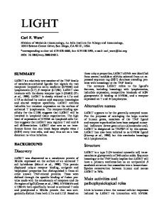
comprises a string of equipment which together performs the desired process step, e.g. digestion with feed tank, heat exchangers, pumps, digester vessel(s), flash vessels, etc. Such a string of equipment is often referred to as a "train", "unit" or "circuit" (e.g. digestion unit, precipitation train, mill circuit). Alumina refinery design generally takes the digestion area as plant bottleneck due to its high unit capital cost and its requirement for constant flow for optimum performance. The design / initial refinery production capacity of greenfield projects has evolved over time from about 0.5-1.0 Mt/y alumina 25-30 years ago (e.g. Worsley, Alumar, Aughinish) to 1.4-3.3 Mt/y alumina for more recently constructed and future planned projects (e.g. Lanjigarh, Yarwun, Utkal, GAC). Figure 1 illustrates this trend.
Abstract
Developing a greenfield bauxite deposit nowadays generally includes constructing an alumina refinery. Economics have resulted in ever-increasing production capacities for recently-built and future planned greenfield refineries. Rationale: economy of scale. As a result the complexity of a greenfield project has significantly increased and its capital cost has grown to several billion USD. Important consequences: • Project owners aim at risk reduction through project financing and formation of joint ventures, further complicating project implementation. • Globally only a limited number of (large) companies have the human andfinancialresources to develop greenfield bauxite & alumina projects. • Only a limited number of engineeringfirmshave the required skills and experience to successfully implement these mega projects. • Only large bauxite deposits get developed.
Greenfield Refinery Design Capacity as function of Start-up Year j
;
♦
This paper proposes an alternative development model for bauxite deposits resulting in a more efficient use of resources and a lower threshold to develop bauxite & alumina projects.
2.
Actual
♦■
;^ !
o
Bauxite Deposit Development
♦
♦ T
Planned
♦ ♦
♦
♦
*
«
i
The development of bauxite deposits is sometimes limited to the mining of bauxite for export purposes, which may or may not include drying the bauxite to a certain moisture percentage. Examples are the Boke and Kindia mines (both in Guinea), and the Bintan mine in Indonesia (now closed). In other cases the mine supplies both a local / in-country refinery, as well as exporting bauxite, e.g. the Trombetas mine (Brazil), and the Gove and Weipa mines (both in Australia). In most recent cases the projected greenfield development of a bauxite deposit includes directly or indirectly the construction of a captive alumina refinery. Examples: Utkal (India), GAC (Guinea), Aurukun (Australia), CAP (Brasil), Ma'aden (Saudi Arabia). In some cases the project may be executed in two stages: a first stage of establishing the bauxite mine with (temporary) export of bauxite, and a second stage including the construction of an alumina refinery. A recent example is the Darling Range project of Bauxite Resources Ltd in Australia as stated in press releases. How have greenfield production capacities and more specifically greenfield alumina refinery design capacities developed over time, and did this have a bearing on project implementation?
3.
♦
' 1990
' 2000
i
1
2010
Start-up Year
Figure 1 - Refinery Design Capacity vs Start-up Year Note that actual refinery production capacities increase over time as a result of de-bottlenecking, improved process efficiencies and operations performance, etc. In a paper presented at the ICSOB A 2008 conference [1] R. den Hond even suggests a doubling of design capacity by exploiting overdesign and post start-up installation of novel technology. What has been the rationale for this trend of ever-increasing design production capacities for recently built and future planned greenfield refineries and what are its consequences? 3.2 Economy of Scale The rationale offered for this trend is the economy of scale: an increased alumina production capacity improves the economics (NPV, IRR, VIR1) of a greenfield bauxite and alumina project2. In the context of alumina refinery projects, economy of scale aspects may be applied to Operating Cost and Capital Cost.
Alumina Refinery Capacity Evolution
3.1 Overview An alumina refinery consists of a number of unit operations such as grinding, digestion, evaporation, etc. A unit operation generally
1 NPV=Net Present Value; IRR=lnternal Rate of Return; VIR=Value over Investment (capital efficiency) ratio. 2 Reference [2] provides an overview of bauxite & alumina project economics.
5
3.2.1 Effect on Operating Cost3 To better assess the effects of the economy of scale on Operating Cost, we should consider its major components: • Variable costs: In $/year these costs vary with plant production, at least within certain plant production rates (typically ± 10-15%), examples: bauxite, caustic soda, coal, fuel oil, lime. The overall plant on-line time of an alumina refinery with more than one train / unit / circuit, e.g. a digestion train, is higher than a plant with one train only, as a result of moreflexibilityin equipment operation and maintenance. The effect on plant on-line time is generally limited (indie. 0.2-0.5% abs), however may vary widely and in a specific case could be significant (>1% abs). As a result the plant operates with less interruptions and operating efficiencies (e.g. bauxite, caustic soda, energy consumption) improve, albeit generally to a limited extent (indie. 0.5-3%). • Fixed costs: In $/year these costs do not vary with plant production, at least within certain plant production rates (typically ± 100,000 t/yr), examples: labour, maintenance materials, administration, other fixed costs. This is the area on which the economy of scale potentially has the largest effect, i.e. a drop in cost per tonne of alumina produced, due to the "dilution" of "fixed" annual expenses by a larger production volume. This applies particularly to labour and otherfixedcosts. If the increase in production capacity includes an increase in the number of trains, this positive effect is dampened because not just the size of the equipment involved increases, but also its number. In addition, the requirements of complex and large alumina refineries may result in disproportional increases of overhead costs. The example provided in Table 1 may illustrate the above. In this example the larger refinery capacity is based on an increase in the number of operating units in several areas, resulting in a limited improvement only of thefixedcosts per tA.
1.4
3.2
Variable Costs, $/tA
85
83
Fixed Costs, $/tA
40
34
Total Operating Cost, $/tA
125
117
* Mt/y = million tonne alumina per annum
3.2.2 Effect on Capital Cost4 Economy of scale has the following main effects5 on Capital Cost: • In general larger size equipment, particularly tanks and vessels, is more cost effective per tonne alumina (tA) produced because larger tanks have a smaller surface area over volume ratio than smaller tanks, hence are cheaper in material cost per m3 stored volume. This effect is sometimes known as the "0.6 factor rule"6, and potentially represents a significant drop in capital cost per tA (note: this factor may be different for different equipment types and unit operations). Although technological improvements have resulted over time in a general increase in equipment size available for most processing equipment (vessels, tanks, pumps, mills,filters,etc), there are physical, technical and/or economic limitations to the size of all equipment. In addition, design considerations may favor in specific cases a large number of small equipment over a small number of large equipment. • Infrastructure (both shared and non-shared) costs are diluted (e.g. piperacks, water supply, power distribution), and spare equipment may be shared in case of a larger production capacity resulting in the construction of more units. Both of these result in a lower capital cost per tA produced. As an illustration: for a refinery with two digestion trains, shared facilities represent indicatively 20-25% of its capital cost (includes raw materials handling, general facilities, shared spares, etc). Here too there are limitations: both with respect to sharing of spare equipment and because capacity increases in infrastructure are required at some stage. The overall effect is a drop in capital cost per tA produced at higher production capacities. A straightforward power factor relationship between these would look like Figure 2.
Table 1 - Effect of Economy of Scale on Opex - 1 Refinery Production Capacity, Mt/y*
The conclusion from the above is that the primary effect of economy of scale on Operating Cost is on fixed costs (expressed per tA), and particularly if a capacity increase is the result of an increase in equipment size rather than equipment number.
Power factor relationship of Greenfield Refinery Capex as function of Design Capacity
Table 2 provides an example in which the capacity increase involved an increase in equipment size rather than the number of operating units, illustrating in that case a more pronounced effect onfixedcosts per tA.
Capex * (Capacity),actor
a
Table 2 - Effect of Economy of Scale on Opex - 2
Design Capacity, kt/year
Refinery Production Capacity, Mt/y*
2.8
:::::.3.3::;::
Variable Costs, $/tA
84
84
Figure 2 - Refinery Capex vs Design Capacity - Power Factor
Fixed Costs, $/tA
50
42
Total Operating Cost, $/tA
134
126
In many cases however plant (and thus project) capacity increases are a combination of increases in equipment size and in equipment numbers (e.g. as a result of an increase in operational
* Mt/y = million tonne alumina per annum
4
Reference [4] provides an overview of Capital Cost A second-order effect is an increased plant on-line time as a result of a plant consisting of more than one train resulting in a slightly lower capex per annual tA. 6 Theoretically the factor is 0.67. 5
3
Reference [3] provides an overview of Operating Cost
6
units / trains). In addition, an increased project scope also adds (at some stage disproportionally) to its complexity. As a result, actual capital cost per tA produced may deviate from a smooth curve as shown in Figure 2. In fact Canbäck and others [5] refer to Bain who found in a study of twenty industries that at the plant level, beyond a minimum optimum scale few additional economies of scale can be exploited. Available information suggests for the alumina industry that with respect to the relationship of refinery capital cost and design capacity, a differentiation can be made in two design capacity ranges as illustrated in Figure 3: • Up to about 1.5 Mt/y: a power factor of -0.7. • Above about 1.5 Mt/y: a power factor of -0.9.
Table 3 - Effect of Capacity on Overall Project Economics Refinery Capacity
Capital Cost*, M$ Mine 115 Refinery 1,635 Infrastructure 500 (railway, port, town) Total Capital Cost*, M$ 2,250 $/AnntA 1,500
Greenfield Refinery Capex as function of Design Capacity
3 Mt/y
L5Mt/y
200 3,000 680 1,293
3,880
Operating Cost, $/tA (incl. Infrastructure opex)
137
125
Sustaining Capital, $/tA
8
8
Economics* (indie.) NPV(8%), M$ IRR, % Payback period, y
-139 7 10.5
369 9 9
* Basis W Europe, Mid 2010 US$ Alumina price at 325 $/tA
#
«ex -s- Capacity""0!7
Table 3 shows that, despite the Refinery capex per annual tA for the two options following the trend illustrated in Figure 3, the overall project economics flip from a significant negative NPV (with IRR 7% and payback period 10.5 years) to a significant positive NPV (with IRR 9% and payback period 8.5 years). A major contributor is the disproportional increase in $/tA of the Infrastructure capex. To underpin that: had the delta in capital cost between the two project options expressed in $/Annual tA remained unchanged from the delta between the two refineries, the economics of the 1.5 Mt/year project (in that case at a total capex of 1,383 $/AnntA) would have looked as follows: NPV(8%) = -12 M$; IRR = 8%; Payback period = 9.5 years. On re-considering the trend shown in Figure 1, the reasoning could be turned around: a disproportionate increase in project scale is required to result in acceptable economics. In a similar context, A. Kjar in his paper presented at the TMS 2010 Annual Meeting [6] discusses in general terms the uncompetitive capital cost of recent Western-developed greenfield alumina projects as a result of (among other reasons) large project size and increased project complexity.
Capex * Capacity 0 β
appro«. 1.5 M t / y
Design Capacity, kt/year
Figure 3 - Refinery Capex vs Design Capacity From Figure 3 it would appear that although further gains in capital cost per tA are possible at design capacities above -1.5 Mt/y, these will be limited. A design capacity of about 1.5 Mt/y for an alumina refinery might perhaps be the "minimum optimum scale" referred to by Canbäck. Note that 1.5 Mt/y is meant to be indicative only. This raises the question how this result can be reconciled with the design capacity of some future planned projects which are well above 1.5 Mt/y (refer Figure 1).
3.3 Consequences The indicated increase in the design / initial capacity of greenfield (bauxite mine and) alumina refinery projects over the past decades has had the following major consequences: • The complexity of these mega projects7 has increased significantly, especially in terms of project planning and management. Significant infrastructural works are often required, involving extensive government involvement, adding to project complexity. • Project capital cost has grown to several billion USD, and project owners reduce risk through projectfinancingand the formation of multi-party joint ventures. This is perfectly reasonable, however it complicates project implementation (e.g. with respect to decision making processes). • Due to thefinancialcommitments involved, globally only a limited number of (very) large companies have the financial and human resources to develop greenfield bauxite & alumina projects.
3.2.3 Infrastructure Costs & Overall Economics The explanation for the above result is that greenfield projects have infrastructural requirements which may include access roads and bridges, a railway line, port facilities, and employee living facilities. In case of extensive infrastructural requirements, the related capital cost is significant and has a disproportional bearing on the economics of a smaller capacity greenfield project. An example may illustrate the above for two greenfield project options at the same location: option 1 at 1.5 Mt/year alumina production design capacity, and option 2 at 3 Mt/year. Assumed infrastructural requirements for this location: • 100 km railway line. • Jetty and wharf, and ship loading/unloading facilities at the alumina export port. • Employee housing and living facilities. Table 3 provides indicative numbers for capital, operating and sustaining capital costs for the two options considered in this example and their economics.
7
7
Typically projects over 1 billion US$.
•
•
Table 4 - Greenfield 1.5 Mt/y Aa Refinery Capital Cost (typ.)
For the same reasons (project scope, complexity), only a limited number of engineering firms have the required engineering, construction and project management skills and experience to successfully implement these projects. Typically a project life of 30+ years is (implicitly) applied to justify the significant investment of a greenfield bauxite & alumina project. Reason: an alumina refinery can operate effectively for decades (refer e.g. Paranam, Gove, Kwinana, QAL). For greenfield bauxite & alumina projects with a captive refinery this means that the bauxite deposit on which a project is based should be able to sustain refining operations for such a period. Therefore only (very) large bauxite deposits are developed, indicatively 200-300 Mt and more.
Cost Item Direct Costs Equipment* Commodities* Total Direct Costs, M$ Indirect Costs Freight EPCM Temp. Construction, start-up, Commissioning, etc Owner's Engineering & Other Costs Total Indirect Costs, M$ Contingency, M$
In summary, worldwide only a small number of companies develop mostly very large greenfield bauxite and alumina projects, which often take a decade and more to develop.
Total Refinery Capital Cost*, M$
231 539
770
78 256 180 190 704 161 1,635
* Incl. steam & power generation, sub stations, residue disposal, water supply, communication & info systems # Incl. concrete, steel, mechanical bulks, piping, wire and cable, etc & Basis W Europe, Mid 2010 US$
3.4 Where from here? With an objective to lower the threshold for the development of bauxite and alumina projects, the question may be asked if the underlying trend, viz. ever-increasing alumina refinery design capacities, is inevitable, or if viable alternatives exists. The basic reason for the trend being economics (refer section 3.2), the question could be reformulated as follows: is it possible to develop smaller greenfield bauxite and alumina projects at acceptable economics? A. Kjar addresses this question and some of the issues discussed above, albeitfroma different perspective, in his earlier mentioned paper. He indicates that as a means to overcome some of these issues, attempts were made by others: 1. To gain improved control over the project execution process; and 2. To increase the level of pre-assembly to reduce total costs of on-site construction labor and low productivity - refer also a paper by R. Valenti and P. Ho [7]. A. Kjar proposes the use of replication of a modern plant design, and small increments of capacity (without quantifying a capacity), in order to quickly and more cost-effectively build a large plant / project. Although A. Kjar's paper has a different angle (viz. building a large plant at lower capital cost), there are overlaps with the subject of the current paper (investigating the possibility to lower the threshold for the development of- smaller - bauxite and alumina projects). To further explore the subject, a more in-depth look at the makeup of a greenfield project's capital cost is required.
4.
1.5 Mt/y
4.1.2 Commodities and Plant Layout Aspects Table 4 illustrates that the Commodities represent a very significant element in the refinery capital cost. Commodity amounts and their related capital costs reflect plant design including plant layout. Current alumina refinery layouts are designed to accommodate additional (future) digestion units (and all of the other required process units - e.g. precipitation, evaporation). The consequence is that plant design is not optimized for its initial production capacity. Plant layout is characterized by an "open architecture", at best compromising between on the one hand the limited layout requirements for the initial / design capacity and on the other hand the more extensive requirements to accommodate future additional process units. And in the worst case consisting of a layout of a large-capacity plant of which part is built, resulting in an inefficient plant layout for the design / initial capacity. In addition, in some cases plant design includes equipment which at some future stage might be used to its full capacity, but operates (well) below design for a considerable part of its lifetime. 4.1.3 Alternative Approach - Dedicated Plant Capacity A. Kjar's proposal to use replication means that a design is developed for a dedicated production capacity. Or putting it differently, this alternative design approach aims at designing an alumina refinery for a dedicated production capacity, i.e. without provisions for future expansions. This approach enables optimizing plant layout for the targeted production capacity, e.g. with respect to positioning similar equipment close to each other, use of common spares, etc. This more "closed" layout architecture results in a more efficient plant layout, reflected for example in the design of main plant piperacks. This is illustrated in Figure 4 which shows the main piperack layout for a typical (current design) 1.5 Mt/year capacity refinery ( i.e. in the expectation that additional production lines in the various areas will be added in the future), and the layout for a dedicated 1.5 Mt/y capacity alumina refinery (same scale). The alternative approach with its more closed layout design impacts positively on commodity volumes: for the same production capacity, commodity volumes for a greenfield plant designed along this alternative approach are similar to that of a brownfield expansion of an existing refinery. This is illustrated in Figure 5 which shows the total length of piping of greenfield and
Capital Cost Make-up
4.1 Refinery Capital Cost 4.1.1 Overview The capital cost of a greenfield alumina refinery may be split up as shown in Table 4. In this table typical numbers are shown for a low-temperature digestion alumina refinery with a 1.5 Mt/y production capacity. Note that actual numbers may deviate significantly as a result of bauxite quality, technology choices, plant location, etc.
8
reflected in lower Commodities costs, resulting in lower Direct Capital Costs, in turn lowering Indirect Capital Costs. The overall effect on the capital cost of a greenfield dedicated lowtemperature digestion alumina refinery of 1.5 Mt/y is illustrated in Table 5 (indicative numbers). As can be seen in this table, the alternative approach improves the total refinery capital cost indicatively by over 10%. In fact the capital cost expressed per annual tonne of alumina capacity is lower than that of the current-design refinery at 3 Mt/y capacity (976 vs 1,000 $/Ann tA - refer Table 3).
brownfield projects as function of plant production capacity, and the requirement of a dedicated plant of 1.5 Mt/y capacity. This approach also stimulates focusing on a "lean" design and exploit any potential overdesign right from start-up (refer the comment made in section 3.1). Layout Main Piperacks of Dedicated 1.5 Mt/y Alumina Refinery
Table 5 - Comparison of Refinery Capital Costs (indie.) 1.5 Mt/y Refinery Capacity
Cost Item
Current-design
Typical Layout Main Piperacks of 1.5 Mt/y Alumina Refinery
Direct Costs Equipment* Commodities Total Direct Costs, M$
231 539
Indirect Costs Freight EPCM Temp. Constr., start-up, Comm. Owner's Eng. & Other Costs Total Indirect Costs, M$
78 256 180 190
Contingency, M$
1
Total Capital Cost*, M$
$/AnntA 1,090
Dedicated
770
224* 459 682
704
69 227 175 168 640
161
142
1,635
976
1,464
* The more efficient plant layout enables slightly lower equipment cost as a result of a more efficient use of common spare equipment Basis W Europe, Mid 2010 US$
#
4.1.5 Compact Refinery - Simple & Limited Scope Along the lines of A. Kjar's paper (although he does not quantify "small increments of capacity"), applying the proposed dedicatedcapacity approach to a compact alumina refinery capacity of 0.4 Mt/y results in a project with a simple and much more limited scope. Available data suggest that as a result some Indirect capital cost items decrease more than proportionately, particularly costs related to temporary construction and start-up support, camp and other construction related items, and owner's costs. Table 6 illustrates the capital cost for a 0.4 Mt/y alumina refinery based on a dedicated design (indicative numbers). The table shows that the capital cost per annual tonne alumina (1,295 $/AnntA) is higher than that of the much larger 1.5 Mt/y dedicated plant (976 $/AnntA - refer Table 5), however is at a level which could result in a project with acceptable economics, provided Infrastructure capital cost is limited (compare with the 1,293 $/AnntA for the overall project capital cost of a 3 Mt/y refinery - see Table 3). Table 6 also shows that the total capital cost is at a level which would enable many more (relatively small) companies to develop such a project without necessarily requiring the formation of multi-party joint ventures, simplifying overall project management and thus enabling to lower costs (effect not included in Table 6). Note that the 0.4 Mt/y refinery production capacity used here is notfixedbut is meant to typify a capacity range of ~ 0.3-0.6 Mt/y. The higher end of this range is limited by the objective to end up with a total project capital cost well below 1 billion US$, the lower end is determined by logistical limitations (e.g. with respect to caustic soda and fuel oil shipments) and may vary for different locations.
h Figure 4 - Main Piperack Layout Comparison 400,000
Total Piping as function of Plant Capacity
Greenfield
Brownfield Plant with dedicated layout design
Plant Capacity, t/y
Figure 5 - Total Piping as function of Plant Capacity 4.1.4 Effect Alternative Approach on Commodities Cost A dedicated greenfield plant design results in lower amounts (in some cases significantly lower amounts) per annual tA produced of commodities such as steel, concrete and piping. This is
9
project with a simple and limited scope, further improving capital cost per tA produced. To ensure acceptable economics, Infrastructure capital cost should be limited. At the same time such a project has few infrastructural requirements , especially if located close to an existing port.
Table 6 - 0.4 Mt/y Refinery Capital Cost (indie.) Cost Item
Direct Costs Equipment Commodities Total Direct Costs, M$ Indirect Costs Freight EPCM Temp. Constr., start-up, Comm. Owner's Eng. & Other Costs Total Indirect Costs, M$
0.4 Mt/y Refinery Capacity (dedicated design) 95 177
28 91 37 33
Contingency, M$ Total Capital Cost*, M$ $/AnntA
* Basis W Europe, Mid 2010 US$
5.2 Main Advantages The main advantages of the new development model are: • Due to the significantly smaller project capital expenditure involved (lower risk), this approach enables the development of bauxite & alumina projects by smaller companies without a need to form multi-party joint ventures, i.e. it increases the number of companies potentially interested in developing bauxite deposits. In other words competition increases, which should result in more efficient use of resources, both in terms of capital resources and in terms of global bauxite deposits. • Due to the decreased complexity of compact alumina refining projects, the number of engineering companies potentially able to develop these projects increases, again resulting in more competition and the potential for a more efficient use of resources. • Small and simple projects carry less risks and require less time to develop, implement and start-up, all of which has a positive impact on economics. • A long term alumina refining project based on the new model requires only a relatively small bauxite deposit (a deposit of ~40 Mt could support a 0.4 Mt/y project for 30 years). This means that worldwide the number of bauxite deposits that lend themselves to development increases. • The new development model may be applied also to the development of part(s) of a large deposit. • This approach may in some cases lower the threshold to increase value creation through alumina refining rather than being limited to bauxite export sales. This is attractive both to host countries and to companies developing potential bauxite & alumina projects. • In some cases, an adapted version of this new development model may enable bauxite deposit development even in locations with little existing infrastructure, albeit at a larger than compact scale (refer e.g. to Table 5 for a dedicated 1.5 Mt/year capacity project).
272
189
!
57 1,295
518
4.2 Infrastructure Capital Cost As mentioned above, in order to realise acceptable economics for a project based on a compact dedicated production capacity, Infrastructure capital cost should be limited. Conversely a project based on a compact plant capacity has very limited infrastructural requirements and has several advantages over a large plant, particularly if the project is located close to an existing port, e.g. it may be allowed closer to residential areas (i.e. is closer to existing infrastructure); the existing infrastructure may be sufficient for a small plant, but not for a big plant; a suitable location for a small residue disposal area is easier to find than for a large one, etc. As outlined in section 5.3 several such locations exist worldwide. 4.3 Refinery Technologies Note that the alternative approach proposed above is independent of the selected refinery technologies, while at the same time stimulating to focus on improvements, e.g. positioning similar equipment close to each other, the use of common spares, etc. 4.4 Replication and Indirect Costs A. Kjar indicates in his paper that the use of replication of a modern design at small capacity increments has as one of its main advantages far lower indirect capital costs, comprising Project management; Procurement; and Technology & EPCM fees. Although no direct quantification is mentioned in the paper, this appears consistent with the results discussed above for a dedicated plant design at a compact production capacity. Some of the replication-related cost savings mentioned by A. Kjar may come on top of the cost improvements indicated in this paper.
5.
5.3 Possible Locations Following are some examples of bauxite deposits that may lend themselves to development via the proposed alternative approach (between brackets the potential alumina export port): • Haden, Queensland, Australia (Brisbane). • Bindoon, Western Australia (Fremantle). • El Palmar, Venezuela (Ciudad Guayana). • Trelawny, Jamaica (Discovery Bay). • Kibi, Ghana (Tema). The above list is not exhaustive and meant to be illustrative only. In addition some bauxite deposits which in view of their size could support the current development approach with largecapacity alumina refining projects, may also lend themselves to stage-wise development through the proposed alternative
New Bauxite Deposit Development Model
5.1 New Development Model The bauxite deposit development model proposed in this paper as detailed above is based on the development of a dedicated compact alumina refinery in the range ~ 0.3-0.6 Mt/year. The dedicated refinery design has no provisions for future expansions, enabling optimizing plant layout and resulting in lower capital cost per tonne of alumina (tA) produced compared with current plant design. The compact capacity results in a
10
approach. In this case these deposits would be able to support several (smaller) greenfield bauxite and alumina projects as outlined in the last bullet point of section 5.2 above. Example: some of the Eastern Ghats deposits in Orissa and Andhra Pradesh, India, e.g. the Kutrumali deposit (with Visakhapatnam as potential alumina export port).
6.
References
1. R. den Hond, "Technology Choices for Greenfield Alumina Plants" (paper presented at ICSOB A 2008, Bhubaneswar), pp 267-270. 2. P.J.C, ter Weer, "Greenfield Dilemma - Innovation Challenges" (paper presented at Light Metals 2005, San Francisco, California), pp 17-22. 3. P.J.C, ter Weer, "Operating Cost - Issues and Opportunities" (paper presented at Light Metals 2006, San Antonio, Texas), pp 109-114. 4. P.J.C. ter Weer, "Capital Cost: To Be or Not To Be" (paper presented at Light Metals 2007, Orlando, Florida), pp 43-48. 5. S. Canbäck, P. Samouel, and D. Price, "Do Diseconomies of Scale Impact Firm Size and Performance - A Theoretical and Empirical Overview", Journal of Managerial Economics, 2006, Vol. 4, No. l,pp 27-70. 6. Anthony Kjar, "A Case for Replication of Alumina Plants" (paper presented at Light Metals 2010, Seattle, Washington), pp 183-190. 7. R. Valenti and P. Ho, "Rio Tinto Alcan Gove G3 Experience on Pre-Assembled Modules" (paper presented at the Alumina Quality Workshop 2008, Darwin), pp 1-5. For further information, please contact P.J.C, ter Weer at
[email protected] or visit www.twsservices.eu.
Light Metals 2011 Edited by: Stephen J. Lindsay TMS (The Minerals, Metals & Materials Society), 2011
STUDY ON THE CHARACTERIZATION OF MARGINAL BAUXITE FROM PARA/BRAZIL Fernanda A.N.G. Silva1'2, Joäo A. Sampaio2, Francisco M. S. Garrido1, Marta. E. Medeiros1 universidade Federal do Rio de Janeiro, Instituto de Quimica, Avenida Athos da Silveira Ramos, 149, Cidade Universitaria; Rio de Janeiro, RJ, 21941-909, Brasil. 2 Centro de Tecnologia Mineral / CETEM-MCT, Avenida Pedro Calmon, 900, Cidade Universitaria; Rio de Janeiro, RJ, 21941-908, Brasil. Keywords: Marginal Bauxite, Mineralogical and Chemical Characterization In this context, the aim of this work was to: ore dress, provide the chemical, structural and mineralogical characterization of crystallized amorphous bauxite (CAB) and compare its behavior and characteristic with the bauxite processed by the Bayer process, such as crystallized bauxite (CB). The techniques applied in this study were: chemical analysis by potentiometric titration and flame atomic absorption spectroscopy, X-ray fluorescence, Xray diffraction, infrared spectroscopy, scanning electron microscopy and thermal analysis.
Abstract Bauxite from Para is divided into five different layers. However, only one is processed. The crystallized-amorphous (CAB) phase is considered a marginal bauxite because it presents a high quantity of Si02reactive and its use depends on special technologies. CAB was characterized and the results were compared with the bauxite used nowadays in the alumina plant. Characterization was performed by XRD, IR, XRF, chemical analysis, TGA and SEM. XRD determined the mineral content: such bauxite is gibbsitic and has been associated with kaolinite and hematite. IR data supported the XRD results. XRF was used to determined the sample's chemical composition. The chemical content of Al203avaiiabie and Si02reactive w a s determined by potentiometric titration and FAAS. The results found for the Bayer process sample were 41.7% and 7.1%, respectively. TGA observed the bauxite decomposition and SEM supplied chemical and thermal analysis. Thus, based on stoichiometric relations of the bauxite components decomposition, it was possible to confirm the presence of the following phases: gibbsite and kaolinite.
I
I
j
j Clay layer (Laterite Soil)
Nodular bauxite
Introduction Crystallized Nodular Bauxite
Bauxites are usually considered to be of two major types: (1) lateritic (sometimes called equatorial) and (2) karst, both being weathered products from the underlying parent rock: lateritic bauxites. [1] Lateritic bauxites, formed in equatorial climates, comprise 90% of the world's exploitable bauxite reserves [1]. The weathering process has resulted in a typical profile in which the valuable aluminous material lies atop of an aluminosilicate base (often clay) and has formed from it through the leaching of silica. The main silicate mineral is kaolinite which is often associated with goethite as the iron mineral. Aluminous minerals are predominately gibbsite and to a lesser extent boehmite [1].
I
Crystallized Bauxite
I
Crystallized Amorphous Bauxite
Amorphous Bauxite
Bauxite from NE Para is divided into five layers: (1) nodular (NB), (2) crystallized nodular (CNB), (3) crystallized (CB), (4) crystallized amorphous (CAB) and (5) amorphous (AB) (Figure 1) [3]. The NB, CNB, CAB and AB layers present a high quantity of iron minerals, reactive Si0 2 and others impurities. [2-3]. These bauxites are considered marginal and their ore dressing requires special technologies arisingfromtheir content of impurities.
Figure 1. Bauxite geological profile from Northern Parâ/Brazil. Materials and Methods
Bauxite mining methods vary according to the nature of the mineralized field bodies, but in most of the cases a strip or block of bauxite is exposed and surface-mined [3]. Although the mining process is selective and only the layer of crystallized bauxite is removed, for a bauxite to be considered economically useful for the Bayer process, the available A1203 content should be between 45-55% whilst the reactive Si0 2 content should be between 4-6%. [4-6].
1 - Sample Preparation The bauxite ore was crushed in a jaw crusher and the product was classified with the use of a sieve (1.65 mm). The coarse fraction was crushed (crushing rolls) in a closed circuit. The -1.65 mm fraction was classified to remove the -37 μιη particles (sludge). The +37 urn fraction was homogenized with the product of the crushing rolls and two samples of 20 kg and 5 kg, respectively, were separated for wet granulometrie analysis. For grinding,
13
samples of 20 kg were homogenized and separated into piles of lkg. Figure 2 shows the block diagram used in the bauxite beneficiation [7].
2 - Chemical and Mineralogical Characterization The bauxite ore was submitted to chemical and mineralogical analysis with the use of: X-ray diffraction, infrared spectroscopy and X-ray fluorescence.
Samples (1 kg) of the final product of the preparation stages were wet ground in a stainless steel mill bar with 10 stainless steel bars of 20 mm diameter. The slurry in water was prepared using a bauxite solid concentration of 1000 g L"1. Grinding time varied from 0 to 30 minutes. A wet granulometrie analysis was carried out after each grinding to adjust the sample to the necessary conditions for the Bayer process [7].
During the ore dressing tests, four different samples were obtained: a work sample (WS) obtained after crushing, two work sample fractions (833 and 208 μπι) and the sludge (-37 μιη fraction obtained after desliming of the -1.65 mm fraction). These samples were submitted to the same characterization techniques of the crude sample.
The granulometrie analysis was carried out with samples of lkg, according to the damp method [8]. A vibratory sifter (684.5 rpm), equipped with a group of sieves with openings from 3.350 mm to 37 μπι, was used according to the Tyler series. All the granulometrie analysis fractions obtained in these tests were dried (100°C) and weighed.
The BP sample (the sample ground to the Bayer process requirement) was characterized with the same techniques used in the crude sample followed by potentiometric titration, flame atomic absorption spectrometry, thermal analysis and scanning electron microscopy. 2.1 - X-Rav Diffraction (XRD)
Feed Aliquot 80 kg (Archive)
«-
1 Homognization
1
Pile
1
Samples were examined by XRD in a Bruker-AXS D5005 diffractometer, with Co Ka (35 kV/40 mA) radiation, 0.02° goniometer velocity and 2Θ by path with 1 s by path counting time and data collected from 5 to 80° 2Θ.
1
2.2- Infrared Spectroscopy (IR)
Crushing (Jaw Crusher)
1
I
Fraction +1.65 mm |
Fraction -1.65 mm
2.3 - X-Rav Fluorescence (XRF)
1
*
Granulometrie -37 μπι «Analysis (Sludge) (3.32 mm to 37 μπι)
Crushing (Rolls Crusher)
1
I
Fraction f -1.65 mm |
Fraction +37 μπι
1
Infrared spectra (FTIR) was performed in a Nicolet Magna 750 Fourier transform spectrometer, from 4000 to 400 cm"1, with resolution of 4 cm'1, with sample mounting using KBr discs.
1 Homogenization
The samples were melted with lithium tetraborate at 1100°C in the proportion of 1:6 sample/fluxing agent. The melted bead was analyzed in an energy dispersive X-ray fluorescence spectrometer (Bruker-AXS model S4-Explorer), equipped with Rh tube. To obtain the semiquantitative chemical analysis, the sample spectrum was evaluated by a Spectra plus v. 1.6 software, in the standardless method mode, without a specific calibration curve.
+ r~ ON 3 |3
1
2.4 - Thermal Analysis (DTA/TGA) Thermal analysis was carried out in a Shimadzu TA-50WSI equipment (thermogravimetric analysis), DTA-50 (differential thermal analysis) in a heating grade of 10°C/min, from room temperature to 1200°C under a flow of air.
Pile
1
1 ws
1
1 (Work Sample) |
1
2.5 - Determination of Available Alumina and Reactive Silica
▼
Granulometrie Analysis (3.32 mm to 37 μπι)
[►
WS833μm WS208μm
The method to determine the amount of available alumina (the amount that will be refined to obtain A1203 in the Bayer process) and the amount of reactive silica (kaolinite), consisted of bauxite digestion in alkaline medium (NaOH) under controlled pressure and temperature, simulating the Bayer process. For the determination of available alumina, a sodium gluconate solution was added to the supernatant to form an aluminum hydroxide gluconate complex. The excess of NaOH, used in the digestion step, was neutralized with the addition of an HC1 solution. Then, a KF solution was added and back titration was carried out. Afterwards, an excess of HC1 in the standardized solution was
1
Grinding - 30 min Bayer Pulp (PB)
Figure 2. Block diagram of the stages used in the beneficiation of bauxite samples.
14
vibration [9, 12,13] and the bands near 3695 are attributed to OH stretching of kaolinite [14].
titrated with a NaOH standardized solution. The solid phase, resulting from ore digestion stage, was dissolved in an HNO3 solution [5]. The concentration of reactive silica was determined by flame atomic absorption spectrometry (FAAS).
In order to compare the mineralogical phases between CAB and CB, it is possible to observe that in CB there are more phases related to iron minerals, such as aluminum-goethite (oc(Fe,Al)OOH), goethite (FeOOH) and hematite (aFe203) [7] than in CAB. These results are associated with the distribution of the layers in the bauxite's profile since the CB layer is near the NB layer, which is composed essentially of iron minerals. For the dissolution of gibbsitic bauxite, the temperature in the Bayer process must be between 140-150°C. At this temperature the iron minerals are inert and do not react during the process.
2.6- Flame Atomic Absorption Spectrometry (FAAS). Chemical analysis was performed by flame atomic absorption spectrometry in an AA6 Varian equipment with 248.3 nm wave number, 0.5 nm slit and with air/acetylene. 2.7 - Scanning Electron Microscopy (SEM) Bauxite morphology was determined by scanning electron microscopy in high vacuum SEM (Leica/F440). The sample was embedded in resin epoxy and polished. The resin was covered again by vaporized carbon to be used as a conductor. Results and Discussion
3526
In this work, the fraction of crystallized amorphous bauxite (CAB) was characterized and the results were compared with crystallized bauxite (CB). The mineralogical phases that compose the crystallized bauxite (CB) were determined by X-ray diffraction (XRD), Figure 3. Therefore, this bauxite is essentially gibbsitic and is associated with kaolinite (Al4(SÌ4Oi0)(OH)8 and hematite (aFe203).
c
o CO
-Ω
0
0 h
I
0
40
2C
60
■ - Al 2°3
80
1
I
1
I
1
I
1
1 I
I
1
1
I
I
1
I
1 I
100
2Θ Γ •
20000
15000
•
c
10000 h
-Al OOH
• -
SÌ
o2
o-Ti02
•
•
10000
*
• 5000
■JJL
0
1
(D
.
10
* .
1
1
20
30
.
-Fe2°3
6000
4000 J
k
-*2°3
A
*
*l
U
•
"
*
lu, A
1
1
1
43
50
60
1 70
.
1 . 1 . I 80 90 100
0
20
40
r
2θ
2Θ / ·
9000 8000
■
• e
7000
-AIO0H • - S Ì O
O-TÌO
■
8000 7000
2
nt ensi t y
- °2
-
m
A Fe
-
Tn
-»2°S
■
A Fe
-
2°3
■
2°3
■
5000
c
Ί
1000
# S
f
o -Ti02
6000
■
2000
• -AIOOH ■
2
■
3000
80
60
■
-
£ 4000
-
■
o
■
3000
Ü
^ill\J'ÌCJvL b
1
0 ι
I 20
ι
1 40
ι
1 60
■
2000
-
■ ■
-
·
wlKJ
1000 ι
1 80
ι 100
0
i
1
1 20
JVJ
40
2Θ / °
WWAJI-ΑΛΛ
_l
1—
60 2Θ
80
r
A-rawore ; B-300°C ; C-450°C ; D-500°C ; E-550°C ; F-600°C
Table III Effect of roasting temperature on surface area of diaspore (6T) Roasting temperature/°C
Raw ore
300
450
500
550
600
Surface area/m2-g_1
1.6205
8.7339
8.4351
38.7462
49.3558
51.0172
36
1(X
84.17% and 95.08%, respectively.
Because the magnetic susceptibility and the dielectric constant vary with specific minerals, the mineral phases in the ore will be influenced in different degrees by intense magnetic field during the roasting pre-treat process. On one hand, the value of Gibbs free energy of each phase will change, resulting in an impact on the stability of the mineral phase. On the other hand, an intense magnetic field also has an effect on the kinetics of phase transformation. The morphology of mineral phases with different magnetic properties would alter, which will affect the mineral structure and properties.
Acknowledgement This research was supported by the National Natural Science Foundation of China (NO. 51004033) References 1 . CHEN Wankun, PENG Guancai, Intensified Digestion Technology ofBauxite(Beijmg: China Metallurgy Industry Press, 1998), 112-116. 2 . WANG Yiyong et al, "Effects of Microwave Roasting on Leaching Behavior of Diaspore Ore", The Chinese Journal of Process Engineering, 2(2004), 317-321. 3 .R A Hind, K S Bhargava, C Stephen, "The Surface Chemistry of Bayer Process Solids: a review", Colloids and Surfaces A: Physicochemical and Engineering Aspects, 1-3(1999), 359-374. 4 . Guo Xianjian et al, "Microwave-assisted digestion of diasporic bauxites", Nonferrous Matels, 4(1995), 55-57. 5 . Zhao Qingjie, "Investigation of new digesting process of diaspore", Light Metals, (1)2000,17-21 6 . Lv Guo-zhi et al, "Roasting pretreatment of high-sulfur bauxite and digestion performance of roasted ore", The Chinese Journal ofNonferrous Metals, 9(2009), 1684-1689. 7 . Wang Xi'ning et al, "Effects of Magnetic Field on Solid Phase Transformation", Materials Review, 2(2002), 25. 8 . C C Koch, "Experimental Evidence for Magnetic or Electric field Effects on Phase Transformations", Mater Sei Eng, 2000, 213.
For the roasting of bauxite, proper temperature increases the internal energy, accelerates the molecular thermal motion and leads to lattice distortion and phase transition. So during the process, the energy of the magnetic field will have great influence on specific magnetic species and on the direction of thermal motion of molecules. It increases the internal active energy, the degree of phase instability, the lattice distortion and makes the phase transition less complete, so the leaching ability of the ore is enhanced. When the intensity of the magnetic field reaches 6T, the temperature field and magnetic field interact with each other. The digestion rate decreases with the further increase of temperature. There are several possible reasons to explain this phenomenon. When the intensity of magnetic field is too high, the atoms and molecules will be oriented in a certain range according to the direction of the magneticfield[7~8].So this will hinder the lattice distortion and the transitions of the crystal structure. This decreases the activity of roasted ore and leads to a decrease in digestion rate. So there should be an optimum magnetic intensity, rather than an infinitely high value. Conclusions (1) The digestion performance of diasporic bauxite is enhanced effectively by a roasting pre-treat in the presence of a magnetic field. After pre-treatment under appropriate conditions, the observed leaching temperature decreases by at least 30°C compared with the raw ore. (2) The mechanism of the effect of intense magnetic field in the pre-processing is that the influence of magnetic field varies with mineral phase, due to the changes of magnetic susceptibility and dielectric constant for different minerals. It will affect the value of Gibbs free energy of different phases as well as the stability of the ore. When the intensity of magnetic field is high, the atoms, and molecules will be oriented in a certain range according to the direction of the magnetic field. In higher ranges, the activation effect is weak. (3) The optimal conditions of intense magnetic field pre-treatment are determined as temperature of 550°C, roasting time of 60 minutes, magnetic intensity of 6T. When the roasted ore was digested in the sodium aluminate solution with a mole ratio of 3.1 and alkali concentration of 220g/L at 190°C for 60 minutes, the mole ratio of digestion solution decreases to 1.39 and the absolute and relative digestion leaching rates are
37
Light Metals 2011 Edited by: Stephen J. Lindsay TMS (The Minerals, Metals & Materials Society), 2011
Light Metals 2011 ALUMINA and BAUXITE Bayer Process I SESSION CHAIR
Peter-Hans ter Weer TWS Services and Advice Netherlands
Light Metals 2011 Edited by: Stephen J. Lindsay TMS (The Minerals, Metals & Materials Society), 2011
APPLICATION OF OPERATION INTEGRITY MANAGEMENT IN THE ALUMINA INDUSTRY Carlos Suarez1, Daniel Welshons1, John McNerney2, Jim Webb2 ^atch Associates Consultants Ine; 1600 West Carson Street, Pittsburgh PA 15219, USA 2 Warren - Forthought Ine, 1212 North Velasco, Suite 207 Angleton, Texas 77515, USA Keywords: Process Safety, Operations Integrity Management, Process and Operations Improvement strategy and implementation of such a system in an alumina refinery environment.
Abstract In today's economic environment the Safety of our industry assets - People, Equipment and Processes - have become even more demanding. This paper provides means to apply Operation Integrity Management System (OIMS) to the Alumina Industry. It discusses what OIM is about, its implementation parameters such as cost and time, as well as an effective way to integrate such a system into refineries day to day operations. A series of Key Process Performance Indicators (KPPIs) are presented as well as an Electronic Knowledge Support System (EKSS) Mockingbird ® as a tool to support the implementation of OIMS.
What is OEM Operational Integrity Management (OIM) consists of an integrated set of theories, practices and techniques for ensuring that an industrial facility operates "with integrity", i.e., that the facility's performance is what it should be - no more, no less. A Brief History of Integrity Management The path of integrity management systems began in the United States, where in 1992 the Occupational Safety and Health Administration (OSHA) introduced its Process Safety Management Program. The goal of its 14 strands was to prevent or minimize the consequences of catastrophic accidents caused through the release of chemicals. The program requires a holistic approach that integrates technologies, procedures and practices, creating multiple barriers of protection.
Introduction Alumina refinery operators can use Operations Integrity Management Systems (OIMS) to improve their Process Safety and Operations Performance. Throughout this paper the authors will refer to Process Safety Management (PSM) as an equivalent system adopted by the Highly Hazardous Materials chemicals and petrochemicals operations.
For the oil and gas sector, the impetus behind the development of integrity management systems came from the Piper Alpha disaster in 1988, in which 167 people lost their lives. The inquiry into the disaster produced the Cullen Report, where the primary recommendation was that operating companies should be required to implement safety management systems that ensure safe design and operation of offshore installations.
Alumina refinery safety in the USA is mainly regulated by the Mining Safety Health Administration (MSHA). This branch of the Department of Labor focuses on employee's health and safety aspects related to surface and underground mining operations. The Occupational Safety and Health Administration (OSHA); another branch of the Department of Labor, regulates chemical and petrochemicals operations. It is important to mention this difference since OSHA regulates process safety activities and systems through PSM while MSHA does not. It is up to alumina refineries management to adopt PSM or OIMS elements to cover the safety of their process, their employees and their surrounding communities.
The report specified that such system should draw on quality assurance principles similar to ISO 9000. The Cullen Report's recommendations were accepted immediately by the British government and the new regime that resulted has influenced the development of integrity management systems around the world. The following have been reported as precursors to the Piper Alpha incident:
As the different elements of OIM are presented you will realize that a lot of them already form part of your refinery ISO, Health, Safety and Environmental systems. This makes it easier for the integration, implementation, cost and time reduction to deploy such a system.
• • •
Corporate Pride and Craftsmanship Complaisency rather than Competency Change to the Rules
The initial response by the industry included the following:
The success in implementing OIMS depends among other things on how quick the refinery culture embraces and supports it.
• • •
Once the elements are in place, the deployment, auditing and further improvements can be enhanced by using an Electronic Knowledge Support System. Mockingbird ® and its suite of applications have been successfully used by the chemical and petrochemical industry over the years. This paper discusses the
•
41
Mitigation of smoke hazards Installation of sub-sea pipeline isolation systems Improvements to the "Work Permits" management system Relocation of some pipelines emergency shutdown valves
that they perform in a manner that is consistent and compatible with Company's policies and business objectives. Evaluate and train contractors before starting any work.
The Elements of OEM Below is a brief description of the OIM elements shown in figure 1. 1.
Management establishes policy, provides perspective, sets expectations and provides the resources for successful operations. Assurance of Operations Integrity requires management leadership and commitment visible to the organization, and accountability at all levels. The adoption of such system is driven by the General Manager and his/her team of Functional Managers.
2.
Comprehensive risk assessments can reduce safety, health, environmental and security risks and mitigate the consequences of incidents by providing essential information for decision-making. Mitigating risks at the early stages of design and the continuation in the operation phase is a must.
3.
Inherent safety and security can be enhanced, and risk to health and the environment minimized, by using sound standards, procedures and management systems for facility design, construction and startup activities.
4.
Accurate information on the configuration and capabilities of processes and facilities, properties of products and materials handled, potential Operations Integrity hazards, and regulatory requirements is essential to assess and manage risk. Process Safety Information such as P&IDs, Materials Safety Data Sheets should reflect current operation.
5.
6.
7.
8.
9.
10. Effective management of stakeholder relationships is important to enhance the trust and confidence of the communities where the business operate. Emergency planning and preparedness are essential to ensure that, in the event of an incident, all necessary actions are taken for the protection of the public, the environment and company personnel and assets. Make it a point to run simulations and drills periodically so that everybody involved react according to plan. 11. Assessment of the degree to which expectations are met is essential to improve Operations Integrity and maintain accountability. Involve all levels of the organization in routine audits. Make it a point to discuss results and focus on corrective actions. OIMS11 Elements Driver
Operations
Evaluation
2. Risk Assessment and Management 1. Management Leadership. Commitment and Accountability
Control of operations depends upon people. Achieving Operations Integrity requires the appropriate screening, careful selection and placement, ongoing assessment and training of employees, and the implementation of appropriate Operations Integrity programs. Apply Management of Change when dealing with new personnel assignments, particularly in the plant areas.
3. Facilities Design and Construction 4. Information / Documentation 5. Personnel and Training 6. Operations and Maintenance
11. Operations Integrity Assessment and Improvement
7. Management of Change 8. Third Party Services 9. Incident Investigation and Analysis 10. Community Awareness and Emergency Preparedness
Operation of facilities within established parameters and according to regulations is essential. Doing so requires effective procedures, structured inspection and maintenance programs, reliable Operations Integrity critical equipment, and qualified personnel who consistently execute these procedures and practices. Make sure that Standard Operating Procedures for both Process Operations and Maintenance reflect current systems. Changes in facilities, or managed to arising from level.
Effective incident investigation, reporting and followup is necessary to achieve Operations Integrity. They provide the opportunity to learn from reported incidents and to use the information to take corrective action and prevent recurrence. Monitor and request reports from any incident, no matter how small or insignificant to the perception of the affected.
Ret·, e« mUoM
Figi. OIM 11 Elements Refinery Culture and How to Promote OIM Cultural Attributes 1. Culture is a feature of the entire organization, not just of some of the individuals within that organization. Therefore, if someone — even the general manager — leaves the organization, the culture of that organization should not change significantly.
operations, procedures, site standards, organizations must be evaluated and ensure that Operations Integrity risks these changes remain at an acceptable
2. Culture is on-going — it is not a one-time event. A facility in which everyone is continuously striving to identify and correct problems and to eliminate hazardous conditions has a strong operational integrity culture, whereas a facility which makes only
Third parties carrying out work on the company's behalf impact its operations and its reputation. It is essential
42
Loss of market share is reduced — After an incident, this loss continues until the company's reputation is restored. Adverse publicity and negative public image can have insurmountable effects
spasmodic and irregular efforts to improve such conditions does not. 3. In a strong OIM culture there is minimal disconnect between words and actions. All managers and workers 'walk the talk'; their words and deeds match.
Litigation costs are reduced — These are unavoidable after an incident and can total five times the cost of the regulatory fines.
4. The creation and maintenance of an organizational culture requires leadership from the top. Allowing lower level employees to "do their own thing" does not create a culture.
Incident investigation costs are reduced — Investigating an incident and implementing corrective actions can cost millions of dollars
5. It is difficult for any organization to truly assess the quality of its own culture. It takes an outsider to truly evaluate the quality of a company's culture. Therefore, an organization with a strong OIM culture will make frequent use of outside auditors, inspectors and reviewers to identify areas of weakness and to suggest corrective actions. Moreover, the auditors' reports will go directly to the facility managers
Regulatory penalties are reduced — For many incidents, a fine after litigation can total 1 million dollars or more Regulatory attention is reduced — A major incident usually results in increased regulatory audits and inspections Key Performance Indicators
6. A strong OIM culture is one in which employees and contract workers feel free to report on difficulties and problems, even if those employees and workers are potentially opening themselves up to criticism
Examples of KPIs for Operation Integrity Management are shown infigure2 below.
7. With regard to SHE (Safety, Health and Environmental) issues, the organization places excessive emphasis on the safety term, to the detriment of the health and environmental elements.
% P&IDs Conformance to Current Process Installations As Built Drawings Available and in Conformance Facilty Design and Built per Sound Standards % of Critical Operational and Maintenance Procedures Reviews Completed to Schedule % Compliance with Critical Procedures Material Safety Data Sheets (MSDSlAvailabilityto^^ Mandatory Training Completed to Schedule Personnel Trained on New Standard OperatingProcedures
Prepare and publish a Mission Statement that spells out the organization's stated commitment to operational integrity management principles.
2.
Develop guiding tenets that show how the OIM program is to be implemented.
3.
Develop a detailed program showing how the guiding tenets are to be achieved.
S of Risk Assessment Corrective Actions Completed to Schedule % of Risk Assessments Reviewed to Schedule
man—-
8. A strong operational integrity management culture adapts to new circumstances without its basic values being affected by issues such as economic downturns or the adoption of new technologies. It is suggested here that management can go about creating a strong operational integrity culture by following the three steps shown below: 1.
Leadership Participation in Incidents Investigation Participation in OIM Program Assessment OIM Contribution as Part of the Employees Performance Assessment
EEEEBEEEEEEa All Critical Controls for Process Safety Identified \ of Controls Inspected to Schedule ft of Controls Outside Tolerance % Compliance with Critical Procedures
% of MOC Documents Compliant with Procedures % of Temporary Changes Overdue % of MOC Physically Installed but Awaiting Completion of Documentation
llll Γ
^ ^ ^ ^ ^ ^ Μ ^ — ■
Assessment of Capabilities to Performed Work Deficiencies Corrected Effective Communication
Ü
OIM provides unparalleled capacity for enhanced risk reduction. A company's risk exposure is reduced in the following areas when well-founded process safety systems are in place.
% of Overdue Incident Investigations No of Repeat Incidents Occuring % of Follow Up Corrective Actions Completed to Schedule 1 Lessons Learned from Company and Industry Incidents
a ■ BE ',- m i mm jjuLlma-
No of Emergency Exercises /Desktop Exercises Completed to Schedule Emergency Plan Reviewed to Schedule
Lives are saved and injuries are reduced — Both the personal impact of human loss and cost of deaths or injuries are painful. A solid OIM program can help prevent these costs
% of Inspections or Tests Completed to Schedule % Compliance with Standards and Procedures
Figure 2 - KPIs for OIM Elements
Property damage costs are reduced — In the U.S., major industrial incidents cost an average of $80 million each
OEM Implementation Parameters
Business interruptions are reduced — These losses can amount to four times the cost of the property damage from an incident
43
To succeed in business a company must: • • •
Protect its license to operate Meet ever more demanding regulatory requirements Manage the sustainability of your business
• •
•
Raise stakeholder and public confidence Minimize and, where practicably possible, eliminate the risk of incidents
The cost areas for years 1-5 includes (1) the remaining cost to reach 100 % compliance and (2) the ongoing cost to maintain compliance (or quality) for the remaining years if the company reaches 100 percent compliance in that period.
How to Implement an OIM System • • • • • • • •
The cost for developing the program is described below:
Assign an OIM Manager (or team) Learn from the literature (check key references) Learn by training (from process safety professionals) Learn from other companies - align; network; participate in industry alliances Note strong synergies with ISO, TQM, RMP, Responsible Care Set some clear OIM goals (one tofiveyears) Track performance versus the goals on a regular basis Reassess OIM/plan & modify (every 3-5 yrs)
Developing an OEM Program. The cost, primarily in equivalent labor costs, to bring the OIM program (and individual element programs) from the concept stage through the final design (such as developing an MOC or MI written program that the facility personnel are confident will work). This category also includes the cost of training personnel to be proficient in various OIM activities, such as leading PHAs, leading incident investigations, leading compliance audits, writing procedures, and leading employee training.
The best OIM companies show the following attributes: •
OIM Champions who affiliate themselves with multiple disciplines (e.g., EHS, Engineering, Operations, Insurance) to work collaboratively
•
Functionally having two platforms to identify, analyze, select, implement, control & monitor process; i.e., worst case (top down) and more frequent events (bottom up)
•
Regularly conduct reviews of the OIM program against the defined elements, and
•
Implementing an OEM Program. The cost (again primarily in equivalent labor costs) to do implementation tasks, such as writing operating procedures, updating PSI, doing initial training of operators and maintenance personnel, and performing/documenting Process Hazard Analysis - PHAs. Responding to Recommendations. The cost, primarily capital costs and expenses, to implement improvements to address recommendations from PHAs, MOC hazard reviews and incident investigations. As a rule of thumb $22,000 - $25,000 per P&ID might be used as the cost associated for the development and implementation of an OIM system.
Especially promote risk engineering in the conceptual engineering design phase.
Mockingbird ® (EKSS)
Time
Mockingbird ® is an Electronic Knowledge Performance System widely used by the Chemical and Petrochemical industry to support OIM / PSM systems development, implementation and manage compliance.
Research has shown that the following level of compliance can be attained after the implementation of an OIM system: • • • •
Initial implementation
40% level of compliance First Year (Baseline) 50% level of compliance Second Year 100% level of compliance anticipated in Fifth Year Excellence in OIM program anticipated Seventh Year
The initial population of the system takes place during the "Miracle Month". This period is used for training on the system, designing its structure and have all involved take ownership. Mockingbird ® becomes the portal for all OIM elements and its tools.
Time is dependent on how many documented similar elements the business already have in place in the organization that can be brought into OIM or easily adapted.
.incMocKingbirdd
Cost
MocKingbird® lTts^u
The labor cost for developing and implementing an OIM element can be accounted for in one or more of the following categories: Meetings Writing Reviewing Revising Training/Orientation Pilot testing More revising
44
Conclusions •
~ΤΛ, , ·ι · ι ,Λι · r * OIM can be easily implemented m any alumina refinery for which other systems such as ISO, Safety, Health and Environmental already exists.
•
OIM can be a combination of the elements listed in this paper and those defined for PSM
•
The successful implementation and continuity in the use of OIM depends on the organization commitment to support it
•
It is important that a strong safety culture be promoted and nurtured
•
The existence of other systems such as ISO, Safety, Health and Environmental, etc will make the OIM system implementation less costly and shorter in time
•
Refineries that reach an excellence level of compliance with OIM will also show an overall improvement in financial and operating levels
•
Mockingbird ® and its application suites offer a sound and robust platform on which to manage OIM
CCPS, 'Guidelines for Auditing Process Safety Management Systems", -g ' .- β *. „ (μ« 169-0556-8 ' * '
Further Readings Exxon Management Systems h{tp;//w\vw.