This content was uploaded by our users and we assume good faith they have the permission to share this book. If you own the copyright to this book and it is wrongfully on our website, we offer a simple DMCA procedure to remove your content from our site. Start by pressing the button below!
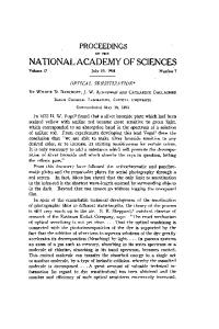
v Linearly ^ Polarized Sample Light
Figure 3.29: Ellipsometer (from Gaertner Instruments).
3,5 Measurement techniques
139
(|)Q = angle of incidence of ellipsometer Pi = polarizer settings for different measurements Aj = analyzer settings for different measurements p = tan xe^^ X = i[180^-(A2-Ai)] A = 360° -{P1-P2)
3.5.1.5
[0<x ng
Once the relationship between the unknown index and the immersion liquid is found, another immersion liquid is chosen so as to bracket the unknown index. Then the bracket is narrowed until the desired degree of accuracy is reached. Finely graduated liquids can yield An = 0.02.
140
Chapter 3 Optical Properties of Insulators—Fundamentals
Monochromatic light must be used, and the temperature of the liquids must be kept at the calibration temperature. Modification: The temperature must be kept relatively constant in the preceding test because the liquid has a strong temperature dependence in its refractive index. This can be used to advantage. Choose a liquid with a higher refractive index than the sample, and then raise the temperature of the liquid until a match is observed. The sample will disappear when the index match is achieved. Since the glass sample will undergo a negligible change in index in a small temperature range, only the liquid index will be assumed to vary with temperature. If the temperature dependence of the refractive index of the liquid is known, then the unknown index can be calculated: n, = rn{T,) + {T^-T,)^
(3.63)
where T^ is the measured temperature where the indices match and T^ is the calibration temperature (usually 20 °C). 3.5,1.6
Femtosecond transit time method
A new method, recently developed by one of our former students, provides an excellent means of measuring the entire dispersion curve for any shape of sample, bulk, or thin film. The method uses the white light pulse from an optical parametric amplifier working off a titanium-sapphire laser. The pulse has a duration of about 100 fs. The pulse is passed through the sample and then matched with a second timed pulse that has traveled through a physical delay line. A diagram of the apparatus is shown in Fig. 3.30. By decomposing the transmitted pulse into its component colors via reflection from a grating, the time taken for each wavelength to transmit through the sample can be calculated. This gives the refractive index at each wavelength directly! The range of wavelengths available is between 300 nm and 1.3 |im. The accuracy is the pulse width divided into the travel time through the thickness of the sample, which turns out to be good to the second decimal place in refractive index for a sample 1 mm thick. The method gives the index dispersion over a broad range of wavelengths, but the accuracy is low and the equipment can cost upward of $150,000. Of course, the Ti-sapphire laser has more critical uses in other optical measurements (see Chapter 7, "Nonlinear Optical Behavior of Materials").
3.5 Measurement techniques
141
Short pulse Ti sapphire laser
Grating] monochromator I Sample Detector
AT
71 ^i=;s-=^ Time delay generator
Figure 3.30: Time delay measurement for calculation of index dispersion in a material.
3.5.2 Infrared absorption and Raman scattering measurements Instruments for IR and Raman spectroscopies are available commercially. Infrared spectroscopy is conducted using either a dispersive spectrometer, which operates much like the UV-visible spectrometer described in the last chapter, or a fast Fourier transform spectrometer. The Fourier transform infrared (FTIR) measurement is conducted using a Michelson interferometer, as illustrated in Fig. 1.25. One of the mirrors is scanned rapidly to give a light pulse in the interferometer. The intensity of the interference pattern is analyzed to give lit) and Fourier-transformed to yield /(co), from which absorbance may be deduced. Raman spectroscopy is conducted by illuminating a sample with monochromatic light from either
142
Chapter 3 Optical Properties of Insulators—Fundamentals
a laser or a high-intensity lamp. Because of the lO'^-lO^ loss of intensity between the incident light and the Raman-scattered light, the spectrometer must be designed to reject strongly the incident wavelength and remain very sensitive to any other wavelength. Usually, a double monochromator is used, whereby the received light is dispersed through a grating, and passed through a narrow slit dispersed again through a second grating, and then passed through a slit before a photomultiplier (PMT) tube. A typical setup is shown in Fig. 3.31. Modifications include using a linear diode array or a charge-coupled detector (CCD) for broadband detection. The advantage of this approach is in collecting a portion of the spectrum all at once, thus allowing for longer integration times than in the scanned photomultiplier tube (PMT). However, since broad-band detection is used, the spatial extent of the detected dispersed light must be large and slits must be open wide. Consequently, supernotch filters that remove a very narrow slice of the spectrum must be used to remove the incident light wavelength. Other modifications include FT Raman for materials that transmit in the near-IR (1 jim). Fourier transform Raman
F=
SECOND MONOCHROMATOR
Mirror
Photomultiplier Tube
Grating g i^-i Mirror
Mirror
-^'
Mirror
ij Grating
Mirror
Mirror
I'
Entrance Lens
FIRST MONOCHROMATOR
Figure 3.31: Sketch of a typical double-monochromator Raman spectrometer.
3,5 Measurement techniques
143
has a lower resolution than the PMT method, so it is particularly useful only with systems that have broad Raman lines, since the technique benefits from a rapid scan of the spectrum. Linear diode arrays and CCD detectors can yield high resolution, but they cannot approach the laser line as well as the conventional method, so low-energy vibrations ('-^P^2^
/ofiv^N
Operator definitions:
Schroedinger equation:
Since the operatorsp and q do not commute {\p,q] =pq — qp ^ 0), it is not possible to factor the left side of the equation as follows: {q^ +P^) 7^ {q -\- ip){q - ip). This is shown here: [9,p]/-(9) = - 1 9 - 9 ^ + 1 - ^ ^ (3.68a)
This suggests: (g2 +p2) = _ [(g + ip)(g _ jp) + (g _ ip)(g + fp)] = 2 [(9^ + iPQ - i„+i(9) (3.71a) Similarly: a+a«l>„(g) = V2(C-l)n(g) a(a+a)«.„(g) = (aa+)ao which is possible only if ^ = 1 = 2^o/'^®o> giving ^0 = 'A'^oo
(3.72)
This gives us the ground-state energy of the simple harmonic oscillator. Returning to the operation of the lowering operator on the ground-state wave function allows solution of the wave function: a%{q) = 0 1
r\
which has a solution of: %{q) = Coe-9'/2
(3.73)
Higher energy levels and their associated wave functions are calculated by applying the raising operator, a+, to o(g). The solutions are Hermite polynomials that obey a generating function as follows: ^"(^^ = ( 2 ^ ) ^ " ^ ' ^ ' ' " ^ ^ ^ where i^„(g) = e+'^/2(0) in t h e direction of an applied compressive stress and a negative change in refractive index in a direction perpendicular to the applied compression. In crystals, the absorption coefficient of t h e propagating light often will vary along with the refractive index. Under this condition, the materials will be called dichroic and will exhibit a variety of colors, depending upon the direction or orientation of the reflected light. Dichroic jewelry is interesting since it changes color with the angle of light incidence and so seems to sparkle. A more general expression of the anisotropic propagation of light in materials is found through the Pockels coefficients. In this case, t h e dielectric constants and the electric susceptibility are expressed as second r a n k tensors, related to the refractive indices as follows for a Cartesian geometry:
172
Chapter 4 Optical Properties of Insulators—Some Applications ^1 = \ / ^ ;
^2 = V^'y
^3 = V^
(4.24)
with Cj = 1/nf. If the Cj are plotted to form an indicatrix ellipsoid in Cartesian space with principal axes m 1,1712 and ^ 3 , the change in refractive index can be written as: (4.25) ^^ij = ^ijk-^k
-^Pijkl^kl
where the E^ are the applied electric fields, the a^i are the applied stress, and 6/^1 are the applied strains. The coefficients z^^ ^^^ ^he electro-optical coefficients; qijki are the stress-optic coefficients; p^ki are the strain-optic coefficients or elasto-optic coefficients. Together the pijf^i and the q^jki are called Pockels coefficients. There are 81 components to Pockels coefficients, obviously reduced by sjonmetry. The stress-optic constant B = -[nV2](gn-^22).
4.3 Photochromic and electrochromic behavior Under prolonged UV exposure, some glasses will darken. This effect is called solarization. One example can be seen in glasses containing Mn and Fe impurities. In such materials, a photochemical reaction occurs that liberates an electron that forms a color center: Mn^^ + Ziv-^Mn^^-fg(4.26) Fe^-^+e-^^Fe^^ The electron, released by the absorbed photon, is trapped by the iron ion. This leaves behind an Mn^^ color center, stabilized by the fact that the electron is trapped to form Fe^"*". The trivalent Mn imparts a violet color to the glass. A reversible solarization or photochromic behavior occurs when Eu^^ and Ti"*^ are present in a highly reduced silicate glass. Under solar exposure (UV light), the following reaction occurs: Eu^-^ -f Ti^-^ F^ Eu^+ + Ti^^
(4.27)
As the light is removed, the reaction reverses and the electron is
4.3 Photochromic and electrochromic behavior
173
thermally excited away from the Ti ion and returns to the Eu ion. These glasses, however, show fatigue effects and acquire a permanent coloration with time. Alkali-boro-alumino-silicate glasses containing silver are much more popular for eyeglass use (Araujo 1977 and Araujo and Borrelli 1991). These glasses contain < 0.7 wt% AgCl. Other components, such as As, Sb, Sn, Pb, and Cu, increase the sensitivity and photochromic absorbance of the glass. In these glasses, the induced absorption results from the formation of colloidal silver during irradiation. In effect, the glass acts as a reversible photographic plate. The metallic silver appears gray and absorbs light. The absorption bands observed are similar to those produced by elliptical but not spherical colloids of silver randomly distributed on the larger silver halide crystals. Small amounts of copper can increase the photosensitivity, so it is assumed that an electron transfer from the silver colloids to cupric ions is the main mechanism of the reverse process. Here, thermal excitation of electrons from the silver colloids and trapping by the cupric ion removes the color after cessation of the irradiation by inducing the recombination of Ag"^ and Cl~ ions. This process is called thermal bleaching. The dominant process is as follows:
cr-^hv=^cf-\-e(4.28a) Ag^+e-=^Ag^ After irradiation is removed: Ag'=^Ag^+eCu^ -\-e- =^ Cu^ (4.28b)
ci^ + Cu^ => cr -f Cu^^ Ag+ + c r => AgCl Boron trioxide seems to play a major role in controlling the size of colloids produced. The major effect that must be controlled is the balance between thermal bleaching and the solarization of the glass. A rapid thermal bleaching process is desired in spectacles in order to regain transparency after sunlight is removed. However, if the thermal bleaching process is rapid, it is also active during solarization, so it reduces the total amount of color achieved during exposure. These processes are controlled by the size of the silver halide crystals, the size and shape of the precipitated silver colloids, and the diffusion distance
174
Chapter 4 Optical Properties of Insulators—Some Applications
between the reacting ions. Optimizing these processes to shorten bleaching time and still obtain sufficient coloration is still the subject of research today.
4.4 Oxides^ chalcogenides^ and halides Transparent crystals are an important class of insulating optical materials; however, we have delayed their treatment to later chapters because their main purpose in optical applications are in nonlinear optics. Consequently, we will cover their properties in detail in those chapters. In this chapter, we will examine glasses as optical materials. Glasses make up an important component of insulating optical materials. The majority of their applications are in linear optics, where they serve an important role. Glasses are desirable for optical elements because of their very high homogeneity, very high transparency, high hardness to allow good polishing and resist scratching, and an excellent optical window over the visible. Their cost is reasonable, but polishing to special shapes can be a labor-intensive process. Glasses in general are metastable frozen liquids that have a noncrystalline structure. Glasses produced from the melt are cooled through a transformation region in which their fluid flow and diffusional characteristics are slowed down until the structure can no longer rearrange itself to maintain the thermodynamic equilibrium of a liquid during cooling. At that point, the glass-transition temperature, the liquid essentially freezes out of equilibrium and continues to cool as a solid. This behavior is commonly seen in the change in volume with temperature (Fig 4.8). If a glass is cooled rapidly through the transformation region, then the frozen-in structure will form at a higher fictive temperature. So while the glass-transition temperature is defined as the temperature at which the glass has a viscosity of 10^^ Pa • s, the fictive temperature can vary drastically depending on quenching rate. Often the glass-transition temperature is defined as the fictive temperature corresponding to a quench rate of l^'/s. Oxide glasses generally have high bandgap energies and multiphonon absorption peaks in the near-IR. Consequently, they transmit between 200 nm and 2.5 jam. Fig. 3.7 shows their relationship between index and
4A
Oxides, chalcogenides, and halides
175
cool rate 1 > cool rate 2 > cool rate 3 > cool rate 4
0
E Liquid state
Tf4
Tfi
Temperature F i g u r e 4.8: Illustration of the variation in the volume and, consequently, the density and refractive index of a glass with cooling rate.
Abbe number. Oxide glasses have indices between 1.4 for the silicates and 2.4 for the titanates. Much work has been conducted on IR-transmitting glasses for a number of applications. The chalcogenide glasses consist mainly of materials t h a t replace oxygen by heavier group 6 elements (S, Se, Te) and replace silicon by heavier metals (Ge, As, etc.). The chalcogenides have generally low bandgap energies and/or numerous absorption bands in t h e visible, so they usually appear black. However, they have good transparency windows in the IR between 1 and 12 microns. Because of their heavy constituents, these glasses have indices well above 2. Halide glasses replace the oxygen anion by fluorine, chlorine, or some of the heavier halides. The more stable halide glasses contain fluorine and heavier metals (heavy-metal fluorides). These materials are characterized by a high bandgap energy and low-frequency multiphonon vibrations. Figure 4.9 gives some representative absorption curves. Consequently, heavy-metal fluorides t r a n s m i t between 200 n m and
176
Chapter 4 Optical Properties of Insulators—Some Applications
100
c o
"cO CO
50
E
f
f A •1
Si02\ \BeF2
i
0
11II
n\
1
\ \
1
2
\\
1 \ l\ 4
1
1
TeX
\ \BIZYT ZBL\
"^^"^l \ 1 11 l\ 6
"1
Ge-Ga-As-S\
8
iV
\
c o
Acrylic
'to
CO
E (0 c
s
200
600
X
800
Wavelength (nm)
1,000
1.200
Figure 4.10: Transmission curves for a representative group of polymers. Loss in the IR comes from multiphonon absorption of light carbon-bonded species (C~H) (after Keyes 1995).
4.6
Sources of color
Color in materials comes from many mechanisms, and differences in color may result from subtle changes in the material's structure. This section will review the many processes that impart color to the appearance of materials. These processes have already been covered in detail in the previous chapters, so in this section we will simply elucidate a few of the more interesting issues pertaining to coloration of materials by some fundamental optical processes. The reader who desires a more in-depth coverage of sources of color is referred to the superb book on the subject by K Nassau (1983). The many sources of color can be grouped into at least 15 categories. These are included in the general topics of: emissive radiation, absorption, reflection, dispersion, scattering, and interference.
-~ ~
Polymer
%T
Index
AbbeNo.
Ally1 diglycol carbonate:
Maximum temperature 212°F
Castable, thermoset, abrasion-reslstant (goodfor spectacle lenses)
CR 39 (PPG) 302°F
ADC
Methyl methacrylate:
Characteristics
92%
1.491
57
200°F
Moldable, impact-resistant, highly stable
88%
1.590
31
180°F
Moldable, less UV resistant, water absorbtive
88%
1.571
35
180°F
Yellowish, low expansion coefficient
90%
1.562
35
190°F
S i m i l a r to SAN but clear
89%
1.586
35
255°F
Highly temperature stable, strong, easily scratched,
Acrylic
Lucite Plexiglass Polystyrene: Lustrex, Dylene Stymn
179
Styrene acrylonitrile: Lustran, Tyril, SAN Copolymer (30/70) styrene/acrylic:
NAS Polycarbonate:
injection moldable
Lexan, Merlon Polysulfone
1.633
Methylpentene polymer
1.466
Terpolymers of acrylonitrile, butadiene, & styrene, ABS
80%
BK-7 glass
>99%
Dimcult to mold, has high shrinkage Close to acrylic, more resistant to temperature, tough, hard to mold
56
Very tough 1.517
Table 4.1: Properties of common plastics.
64
>1,0WF
Excellent as optical material
180 4.6.1
Chapter 4 Optical Properties of Insulators—Some Applications Emission
Emission of light is achieved via a variety of processes. The most fundamental is black-body radiation, which results simply from the thermal agitation of the component atoms of a material. As discussed in Chapter 1, emissive black-body radiation is the source of solar light and light from incandescent bulbs and from fires and hot objects that glow from red to white. Modifications occur when the thermal energy or electric currents are high enough to cause electronic excitations. This is the source of light in sodium and mercury vapor lights, and fluorescent light bulbs. Fluorescence and photoluminescence derive from another source of colored light: the electronic excitation of atoms and molecules followed by a radiative de-excitation process to lower energy. Fluorescence is usually associated with UV excitation, luminescence is associated with excitation by visible light. These processes occur by means of the electronic excitation of atoms followed by radiative de-excitation between lower energy levels. Colors made vibrant by black light come from fluorescence, such as in special chalks. Dye lasers operate by photoluminescence. The emission from solid-state lasers is stimulated by flash lamps or semiconductor lasers. The colors of the light are determined by the energy difference between the electronic states. The same emission processes can be stimulated by electronic currents through a gas, and this provides the excitation for gas lasers. Carbon dioxide laser emission is determined by the difference in energy between pairs of phonon vibration levels of the CO2 molecules; that for He-Ne and Ar lasers results from differences in electronic energy levels. Another source of emissive colors is the recombination of electrons and holes, which is essentially an electronic transition between an excited state and a ground state. Semiconductor lasers owe their emission to this process. All emissive colors are additive, and because of the eye's sensitivity to only red, blue, and green light, all other colors are perceived as the addition of these primary colors (red, green, and blue, RGB). 4.6.2
Absorption
Absorption is a subtractive process in which the color perceived results from the removal of certain frequencies from mixtures of other frequencies or from white light, which is the sum of all colors
4.6 Sources of color
181
(W = R -f G 4- B). Consequently, the primary subtractive colors are made from the removal of the primary additive colors from white light. Thus, magenta is W - G, cyan is W - R, and yellow is W — B. Absorption occurs via a variety of processes. The most common is the absorption of light by electronic excitations between two energy levels. This is the opposite of the emissive process. Thus, transition metals and rare earths have a variety of colors (see Chapter 3) that result from absorption due to electronic excitations of their 3d or 4/* electrons. These states can change with the oxidation level of the atoms. The brown color of beer bottles comes from oxidized iron, while the green color results from the reduced iron. Table 3.5 lists various transition-metal colors. In another instance, the red color of ruby results from absorption of Cr^^ ions in corundum (AI2O3). The green color of emerald results from absorption of the same Cr^^ ion, except that the host is beryl (3BeO • AI2O3 • BSiOg). In both hosts, the Cr^ ion (with three 3d electrons) is octahedrally coordinated by oxygen ions. In ruby, the next-nearest neighbors are Al"*"^ ions. The Cr"^^ absorption bands are in the violet and the green, thus giving a strong red color with a weak blue shade. In beryl, the next nearest neighbors are Si"^^ ions, which bond more tightly to the oxygen ions. Consequently, the cage around Cr"^^ ions is slightly larger, and the absorption bands shift down to the blue and red frequencies, giving the bright green color of emerald. Some absorption processes result from a continuum set of electronic transitions above a given energy level. These materials act as low-pass filters. Semiconductors achieve their color via this process, for the bandgap energy determines the absorption edge. Very low bandgap energies produce black semiconductors, since all visible frequencies are absorbed. As the bandgap energy increases, the absorption edge moves up in frequency and the semiconductors acquire a red, then an orange, and then a yellow color. Eventually, the semiconductors pass all visible frequencies without absorption, and they appear colorless. Oxide glasses are transparent for the same reason. Another mechanism of absorptive color is associated with color center defects in crystals. These result from cation or anion vacancies, interstitials, substitutional, or Frenkel defects (paired vacancies). Amethyst and fumed quartz acquire their color from the formation of color centers in Si02. In amethyst, the substitution of Al^^ for Si^^ traps a hole at the substitutional site. The resulting hole center gives amethyst its purple color. Heating the stone will allow the trapped charge to relax and will remove the color.
182
Chapter 4 Optical Properties of Insulators—Some Applications
Another source of absorptive coloration comes from charge transfer. The transfer of electrons between Ti^^ and Fe"^^ to form Ti^^ and Fe"^^ in sapphire induces light absorption due to the difference in energy between the two states. The absorption process that corresponds to a transition of 2.2 eV is broad and covers from green to red wavelengths, giving a strong transmission in the blue. 4.6.3
Reflection
Reflective coloring is found in metals, as described in Chapter 2. Here, the metal reflects low frequencies and absorbs frequencies higher than its plasma resonance. Copper is red because its plasma resonance is near 2.0 eV (just above the red color, 620 nm). Brass and gold are yellow because they have a plasma resonance at higher energy. Finally, silver reflects across the visible because its plasma frequency is in the near UV (4.0 eV). 4.6.4
Dispersion
Dispersive coloration is found in prisms and in water droplets. Here, the difference in refractive index between different frequencies, or colors, leads to different reflection angles. Dispersive separation of light in glass forms color bands from prisms. In water, the process leads to the formation of rainbows even though the difference in refractive index between the blue and red colors is only between 1.3435 (404 nm) and 1.3307 (710 nm), or only 0.0128. The green flash is a change in color of the sun as it sets. Because of dispersion of the air, there are several images of the sun that are displaced from each other at sunset or sunrise, as would happen with a prism. The blue image is not present due to Rayleigh scattering. The green image is weak and sits above the others. The images then go down in order of yellow, orange, red. Thus the bottom of the sun is red while the top is green. The size of the sun is 30 arc minutes, and the amount of refraction from dispersion is about an arc minute in the vertical direction (e.g., 1/30 the diameter of the sun). The green image of the sun is visible when only the top edge of the rim is visible. The duration of the green image is dependent upon the rate of descent of the sun, so it is very short at the equator and in spring and fall. Consequently, the green flash is more visible at higher latitudes and in the summer. It is best observed
4,6 Sources of color
183
over water. And, since the image is weak due to atmospheric Rayleigh scattering (below), the absence of moisture helps, since water absorbs weakly in the green. Lynch and Livingston (1995) report that members of the Byrd Antarctic Expedition to Little America saw the "green flash" for a period of 35 minutes (Haines 1931).
4.6.5
Scattering
Rayleigh scattering is the source of blue sky, because the strength of the scattering coefficient is inversely proportional to the fourth power of the wavelength. The ratio of the Rayleigh scattering power for a visible wavelength to the scattering power of the red wavelength changes as detailed in Table 4.2. The table shows that the violet wavelength has scattering 12 times greater than the red wavelength. The blue wavelength has 6 times. The result is that the strength of the violet and blue scatterings make the sky blue in color. Our eyes are not as sensitive to violet, and the solar intensity for blue is much higher than violet, so blue dominates. As the optical path length of light in the atmosphere increases, and as the light intensity decreases, Rayleigh scattering is more effective at removing the progressively longer wavelengths from the transmitted light. Thus at zenith, solar light loses only its blue component, but during sunset or sunrise the optical path of sunlight is much longer through the atmosphere and components of longer wavelength are removed. So if the sun is low on the horizon, the rays that graze the Earth have the longest path through the atmosphere and are essentially red, having lost all other wavelengths to Rayleigh scattering. Higher in the sky, the rays traverse a shorter path through the atmosphere and the color of solar light shifts to orange and then yellow. This is the reason why clouds high in the sky reflect yellow while lower clouds will reflect more orange and reddish colors. As the sun sets, the intensity of the light decreases and
Color
violet
Wavelength
400 nm 475 nm 535 nm 590 nm 610 nm 750 nm
Relative Rayleigh scattering
12.4
blue 6.20
green yellow orange 3.90
2.60
Table 4,2: Relative Rayleigh scattering for different colors.
2.30
red 1
184
Chapter 4 Optical Properties of Insulators—Some Application's
more of the rays become red. So what makes lavender clouds? These occur at low light levels after the sun has set. Here, weak red light from the sun mixes with blue scattered light from the stronger illumination higher in the atmosphere to produce the lavender color on the clouds. Mie scattering from larger particles (greater than the wavelength of light) causes essentially wavelength-independent scattering. Mie scattering from micron-sized air bubbles produces grey and white hair color. Mie scattering from bubbles in ice is the source of its blue or white color. The same kind of scattering from grain boundaries in polycrystalline materials forms their white color, or from water droplets forms clouds.
4.6.6 Interference colors Multiple layers with different or alternating refractive index will cause patterns of interference across the visible spectrum if the layer thicknesses are less than a few multiples of the optical wavelengths. For a single layer, interference patterns are formed by adding the light reflected from the air-layer interface to the light reflected from the layerbulk interface. A calculation of the path difference jdelds: Constructive interference :
mX,cos9 = 2d{n2 — nl/n2) (4.29)
Destructive interference :
(m -f l/2)Xcos9 = 2d{n2 — ^11/^2)
where the index of the medium is fix, the index of the film is n2, m is any integer, d is the film thickness, and cosG is related to the angle of incidence and reflection of the light, cj), as: cosG = Ji - {ni/n2)^ sin^ (|)Interference from a thin layer of oil produces the colors in oils slicks or the colors in soap bubbles from a thin layer of soap. Interference processes are a major source of biological coloration. Many biological colors are formed by interference due to regularly spaced reflective surfaces. The hair on butterfly wings forms biological gratings that produce color by interference of light to reinforce various wavelengths either constructively or destructively. The Serica-sericae beatle and the indigo or gopher snake are other well-known examples of iridescent interference coloration. Since interference is strongly dependent on the presence of directional light, this coloration method has distinct advantages for biological systems, because the amount of color diminishes rapidly as direct sunlight decreases. Consequently, objects that are brightly colored
4.6 Sources of color
185
by interference mechanisms during the day become colorless in low light conditions (possibly a survival advantage). Interference is also responsible for the colors on ancient glass. Here, multiple layers of different index are formed by wet-dry cycling of the glass surface, which is etched by water during the wet periods to form a dehydroxylated surface layer. This layer then cracks away from the glass during the dry periods. The fresh glass is etched again as the cycle repeats. The difference in refractive index between the dehydroxylated layers and the air gap between them causes the periodic variations necessary for interference coloring.
Figure 4.11: Rows of precipitated silica colloids in the structure of opals. These produce strong scattering and interference colors.
186
Chapter 4 Optical Properties of Insulators—Some Applications
The color of opal gemstones arises from interference produced by precipitated amorphous silica colloids arranged in regular layers in the structure of the material. The variation in color arises because the order occurs in limited regions and the orientation of the layers varies from region to region. A micrograph of the structure of an opal is shown in Fig. 4.11.
Appendix 4A
Alternate Calculation of Multiple Film Stacks In the calculation of the optics of multiple thin films, an alternate matrix approach may be used. It is similar to that presented in the body of the text in that it calculates the electric and magnetic fields at each interface using the boundary condition that requires continuity of the parallel components of the electric field and magnetic displacement vectors at each boundary. The final results are the same, with a difference only in the expressions used. The electric fields and magnetic displacement vectors can be expressed as follows:
cos k^hi
:^sinA!o/ij
E.i+l H,i+l
Hi
= Mi
E.i+l H,i+l
(4.30)
where the subscript i denotes the ith film. The subscript O denotes the incident medium (normally air), and the subscript s denotes the last medium or substrate.
2n KK = T- [{rii + iyii)di cos %]
187
Chapter 4 Optical Properties of Insulators—Some Applications
188
yp,i
V M^o Ys,o
UQ COS 9O
yp,o
Mo
Ys,s = i/r^"*cos9g
SneWs law :
yp,8"~
^'"
jioCosGj
(4.31)
V^^oCOsG,
no sin GQ = n^ sin Gj = ^2 sin G2 = • • = n^- sin Gj = • • • = n^ sin G^
Denoting the layers by Roman numerals, the matrices for successive interfaces are written as El
=
MiMiiMiji-Mp
Hi
E.'p+i H, p+i
(4.32)
with the product matrix written as: M = Y[Mi=
MiMiiMiii '"Mp=\
^^^
^^^
1^77121
77122
(4.33)
The reflection a n d t r a n s m i s s i o n coefficients are w r i t t e n as:
70^11 + 7o7s^i2 + ^ 2 1 + 75^22 ^^
27o 70^^11 + 7o7s'^i2 H- ^ 2 1 + 78^^22
(4.34)
^^TX^COSG, 7lo COS Go This approach allows calculation of t h e reflection a n d t r a n s m i s s i o n coefficients for a n y n u m b e r of l a y e r s of k n o w n index, t h i c k n e s s , a n d l o s s coefficient. At normal incidence for a s i n g l e film t h e s e e q u a t i o n s reduce to
^
,2^2. ^ nf(rap - n j cos^ikphi) + (npn^ - nf)^ sin''(A!o/ti)
(4.35)
As with Eq. (4.17), if the optical thickness of the single layer is designed to be any odd multiple of one one quarter of the wavelength of the incident
References
189
light [d = X,o/4ni), the condition derived for an antireflective coating is the same:
R^ = 'r'"" . 'X2
(4-36)
which gives a vanishing reflection when n\ = n^n^.
References Araujo, R. J. 1977. Photochromic Glass. In Treatise on Materials Science and Technology—Glass 1: Interaction with Electromagnetic Radiation, edited by M. Tomozawa and R. H. Doremus. New York: Academic Press. Araiyo, R. J., and N. F. Borrelli. 1991. Photochromic glasses. In Optical Properties of Glass, edited by D. R. Uhlmann and N. J. Kreidl. Westerville, OH: American Ceramic Society. Azzam, R. M. A., and N. M. Bashara. 1989. Ellipsometry and Polarized Light. Amsterdam: North Holland. Haines, W. C. 1931. The green flash observed October 16, 1929, at Little America by members of the Byrd Antarctic Expedition. Mon. Weather Reviews 69:117. Keyes, D. 1995. Optical Plastics. In Handbook of Laser Science and Technology. Suppl. 2, Optical Materials, edited by M. J. Weber. Boca Raton, FL: CRC Press. Lucas, J., and J. L. Adam. 1991. Optical properties of halide glasses. In Optical Properties of Glass, edited by D. R. Uhlmann and N. J. Kreidl. Westerville, OH: Americam Ceramic Society. Lynch, D. K., and W. Livingston. 1995. Color and Light in Nature. Cambridge: Cambridge University Press. Macleod, H. A. 1989. Thin Film Optical Filters. 2nd Ed. New York: McGraw-Hill. Nassau, K. 1983. The Physics of Color. New York: Wiley. Simmons-Potter, K., and J. H. Simmons. 1996. Modeling of absorption data complicated by Fabry-Perot interference in germanosilicate thin film waveguides. /. Opt. Soc. Amer. B13:268-72.
This Page Intentionally Left Blank
Chapter 5
Optical Properties of Semiconductors 5.1
Introduction
Semiconductors are characterized by electron mobilities and free carrier densities that are greater than those of insulators but less than those of both good conductors (metals) and semimetals. Typically, semiconductor free charge carrier densities lie between 10^^ and 10^^ carriers/cm^. Unlike metals, semiconductors have an electronic energy gap (0.15.0 eV). This energy gap is a nonzero difference in energy between the highest occupied states and the lowest unfilled states in the electronic band structure. This means that, in principle, undoped semiconductors have no free electrons at absolute zero. All electrons are in valence states. As with insulators, at absolute zero the bandgap energy value defines the energy required to raise valence electrons to free-electron states. There are two types of charge carriers that can be present in semiconducting materials: intrinsic and extrinsic. These types are differentiated by the source of the free charges that dominate transport in the semiconductor and indirectly by the band structure of the material. Intrinsic semiconductors have a bandgap energy sufficiently low that the thermal energy of room temperature {HBT = 26meV) can excite valence band electrons into the conduction band. There they become "intrinsic" charge carriers that can diffuse freely in the material. Intrinsic charge carriers are also those that come from the principal components of the material in pure crystalline form. In contrast, extrinsic charge carriers 191
192
Chapters Optical Properties of Semiconductors
come from dopants, impurities, or structural defects in the semiconductor. Extrinsic charges come from defect levels that may be located either in the bandgap or in one of the bands (conduction or valence) of the material. Since extrinsic carriers arise from local charge imbalances, they do not require thermal activation and so are the only means to provide free charge carriers in semiconductors with larger bandgaps. The same material may be produced in an intrinsic (pure) form or an extrinsic (doped) form. When designing a semiconductor for a given optoelectronic device (i.e., a Si logic chip in a computer), it is common to consider whether or not its operation is one that requires large free charge carrier densities to produce efficient conduction through the device. If the answer is yes, dopant impurities must be introduced into the crystal to produce "extrinsic" charge carriers. Clearly, since intrinsic charge carriers are thermally excited, their concentration is strongly temperature dependent. The concentration of extrinsic charge carriers has a weaker temperature dependence. Extrinsic charge is added by having either excess electrons or holes; thus, different dopants are used to increase the concentration of specific defects. If the dopants are donors, they have excess electrons and increase the electron concentration. These make the semiconductor n type. If the dopants are acceptors, they have too few electrons; thus they provide excess positive charge, or holes. These make the semiconductor p type. Both intrinsic and extrinsic charge carriers in semiconductors can be thought to exist in "free" states. As free carriers, they travel through the material with essentially little interaction. However, it is the nature of the "essentially little interaction" that influences the behavior of semiconductors. Clearly, the charge carriers are not really free, since they must interact with the ionic cores forming the matrix. However, within the confines of the material, they act as nearly free carriers (Fig. 5.1), and any interaction is taken as the source of perturbations in their behavior. Consequently one turns to a "nearly free" electron model to describe the basics of semiconductor behavior. The fundamental principle here is that the free-electron behavior is dominated by wave-like characteristics. So understanding the behavior of electrons in a semiconductor requires an examination of both real and wave-vector spaces. To understand the behavior of electrons in real space we consider a reasonably homogeneous material at large sizes. Generally, one need only consider the graininess of the matrix when sizes on the order of the
193
5.2 Free-electron gas (Sommerfeld theory)
Surface potential
Surface potential
nearly-free carrier
Potential from the ionic cores in the bulk
Figure 5.1: Illustration of nearly free charge carrier in a semiconductor. Away from the surface of the material, it is affected by the periodic potential of the ion cores. unit cell are important. In reciprocal space the opposite is true: Longwavelength or small wave-vector behavior can be treated as a continuum in bulk materials, and the crystal structure of the matrix comes into play only at short wavelengths or large wave-vector values. Recent studies of quantum confinement behavior have examined semiconductor samples whose size is of the order of several unit cells of the crystal. At these small sizes, both real and reciprocal spaces are affected, even at small A-vector values. The next sections examine the free-electron and nearly freeelectron models of semiconductor behavior.
5.2
Free-electron gas (Sommerfeld theory)
The free-electron approach solves the Schroedinger wave equation with no potential energy term (the electrons are totally free). This is clearly useful only in the continuum approximation and must fail at large wave vectors (k) and short wavelengths, when structural, periodic graininess becomes important. The nearly free-electron model (section 5.3) applies modifications through the Bloch theorem, which requires that the wave function be periodic in the same way as the ion cores.
194
Chapters
Optical Properties of Semiconductors
The Schroedinger wave equation without potential energy simplifies to
where ^ = Aco is the free-electron energy, a constant independent of time and position. The wave function solution, \|/, without boundary conditions is v | / , = - ^ e ' * •-'«''
(5.2)
The free-electron energy is calculated from the solution of the differential equation with the following result:
i^{k)=E^^l±-
(5.3)
The parabolic dependence of the free-electron energy, ^, on momentum or A-vector is shown in Fig. 5.2. The addition of boundary conditions forms the 'Nearly-Free Electron Model'.
5.3 Nearly free-electron model The Schroedinger wave equation for electrons in a crystal involves terms for the kinetic energy of the electrons, terms for the kinetic energy of the ionic cores, and terms for the potential energies of the core-core Coulomb interaction, core-electron Coulomb attraction, and electron-electron Coulomb repulsion. These terms must be summed over all ionic cores and all electrons. It is possible to simplify the problem first with the BornOppenheimer approximation. Here, we note that the ionic cores are much more massive than the electrons, so the electronic motion is much faster than that of the ions. Thus, the electrons are moving in an essentially static field of ions. The ions see only the time-averaged motion of electrons (adiabatic approximation). The Schroedinger wave equation is then separable into three terms: the ion interaction, the electron interaction, and the ion-electron interaction. The ion interaction is important in calculating materials structure and makes up an extensive field of quantum chemistry, beyond the scope of this book. We will ignore this part and assume that when the materials are crystalline they are perfect crystals, and deviations from perfections are discussed in terms of defects.
195
5.3 Nearly free-electron model
-Zn/a
-27i/a
-7i/a
0
nia
27i/a
Ma
Wave Vector, k
Figure 5.2: Parabolic dependence of the energy on wave vector for a free carrier wave function. The electron-electron interaction is generally handled as a perturbation of the electron-ion interaction. So we are left with considering the ionelectron interaction, which is divided into two parts: the ion-electron Coulomb interaction with frozen ions, which we analyze shortly, and the interaction between electrons and moving ions (thermal vibrations of the lattice), which is treated through electron-phonon interactions.
5.3.1 Bloch theory In treating the ion-electron Coulomb interaction, the effect of the periodic lattice on the nearly free electron is treated by considering a periodic potential function in the Schroedinger equation: 2m
V'v|/-fX^[7,,.v|/ = ^v|/
(5.4)
ij
where the potential energy is summed over all ions and electrons. For the nearly free-electron approximation, we replace the sums with a periodic function: f7(r) = [7(r -f Rq) = U{r + AiRq), with Rq representing the lattice vectors in the direction of the periodicity. The Bloch theorem suggests a solution that requires the wave to
196
Chapter 5 Optical Properties of Semiconductors
exhibit the periodicity of the lattice through the following solution to the spatial part of the Schroedinger equation: ^nkir)^e"'''-Unk{r)
(5.5a)
where U^k{r + R) = U^kir)- Thus, v|/„,(r + i?) =e'*-(«+'-)C7„,(r) =e'*-«v|/„,(r)
(5.5b)
The wave function component, Uj^k{r) reflects the periodicity of the lattice with the spatial period R, The condition expressed in Eq. (5.4) is true for all integers (n^) that are multiples of the unit cell dimension (a) as follows: R = Aijtt. One can calculate the allowed values of k as follows (with n = integer), by taking the highest periodicity with R = a: v|/,,(r + a)=e''^>,,(r)=v|/,,(r)
(5.6a)
Thus,
K =
^-^
(5.6b)
a
A sketch of the effect of a periodic line of atoms on a series of ID wave functions is shown in Fig. 5.3. The total solution sums over the various k values and multiplies with the temporal term to produce the following: ^.(r, t) = Yls{mnkir)e-i^'^^^'^'
(5.7)
k
where the g(k) are the weighing functions for the various k components. The condition just set up for the carrier wave function reflects the periodicity of the lattice of ionic cores. This means that when the ^-vector is small (e.g., the wave functions have long wavelengths), the periodicity spans many unit cells of the lattice. As k grows, the wavelength shortens and spans fewer lattice sites. At some point the graininess (atomic nature) of the lattice begins to influence the dispersion relation (energy vs wave vector: co vs k) behavior of the material. At the limit, it is clear that when the wavelength of the carrier wave function is twice the atomic separation, o, in the lattice, this forms the minimum wavelength that the wave may sustain, since there are no atoms in between to define a higher frequency or shorter wavelength. This limit occurs when the kvector equals n/a. This point is defined as the edge of the Brillouin zone of the crystal for the particular lattice direction in which a is the lattice
5,3 Nearly free-electron model CO
c o
197
1 A."'./y"^(\/'"A
A''-/V'
—A •* A7n K 1 •
f\l;
c
=3 UL
JO
O
'E
2
•1 /1U /M\ M /•l ^M 1 •' If 1 • 1 1 * 1 J • 1 1 • If 1 ' 1
1; A 1 \\ 1: 1 A •1 1/ /( / \\
1. '1 1
\/
At' n+2 \l
^Ai*/n+4 \ i
'
.1 1
• 1L * 1 Ji * I/I */' 1
Ik /M
IB
.1 1• 1 l \ •! I* / l 1 •1 l/\l '\l' \n'\l'/\l -l 1/ \l U' \ v\/'/1/ • LU
/./
II* 11' 11' I 1'
«1 1
1
MM
1 11 • 1
n+6
1 ' 1/ 1 * 1 I1f * IV 11 * 11 1
// '•W n+8
Periodic Position of Ionic Cores F i g u r e 5.3: Allowed wave functions that satisfy the Bloch condition at high frequencies. The solid line represents the highest wave vector allowed at a value of 7c/a. The dotted and dashed lines correspond to smaller k values (e.g., longer wavelengths).
spacing. It is clear t h a t this atomic separation is different for different crystallographic directions. The Brillouin zone changes with crystalline orientation. Thus, it reflects the structure and symmetry of the reciprocal of the crystal lattice. As the ^-vector is increased beyond t h e zone boundary, t h e wavelength of the wave function cannot get any shorter, so the energy dispersion folds upon itself. Thus, only t h e first Brillouin zone {-n/a i 0) c LJJ
\ -2nla
-7t/a
0
nla
2nla
Wave Vector, k F i g u r e 5.4: Effect of the Bloch condition on the energy dispersion. Because the shortest wavelength allowed is 2a, there must be a break in the energy dispersion at that value as shown in the diagram. The region between — n/a. and -f Tc/a is called the 1^*^ Brillouin zone. The higher k-values only repeat the same wavelengths in the V^ Brillouin zone.
spending to electronic states from the second, third, fourth, etc. Brillouin zones. At small values of k, the effect of the underlying ionic core crystal structure is negligible, and the energy still follows a parabolic dependence on /j. At large values, t h e effect of a grainy matrix becomes important and one must consider the effect of the Brillouin zone boundary. An important readjustment is necessary in t h e definition of both velocity and mass in order to treat t h e nearly free electron within t h e confines of energy and momentum conservation. The electron's velocity is written as the group velocity of the wave: ^^
dk
hQk
h^^
(5.8)
An effective mass is defined for t h e free electron and t h e free hole by t h e rate of curvature of the band-dispersion (^ vs k) curve:
(f%
m eff = h' dk^
1-1
(5.9)
For electrons in a band, there can be regions of high or low curvature (different from the parabolic curvature). This reduces or enhances t h e effective mass. The foregoing definition allows u s to apply t h e same dispersion relations to the Bloch waves as are used for t h e free electrons. Consequently, they maintain t h e same energy dispersion equation for t h e
5.3 Nearly free-electron model
199
entire band, whether near or far from the Brillouin zones. Thus, we may write in general: ^=^
(5.10)
The crystal does not weigh less if/^eff <meiectron> but Newton's second law is obeyed throughout the crystal by use of this definition. Clearly, to a first approximation (parabolic approximation), the effective mass is approximately the electronic mass at /? = 0, but it goes to infinity as k approaches ± n /a at the Brillouin zone (BZ) boundaries. In the region near A = 0, the dispersion is parabolic; thus the momentum is represented by the Bloch wave vector (p = hk). Nearer the BZ boundary, there is an increase in the reflected component of the wave function due to Bragg reflection from the periodic lattice. This corresponds to a negative momentum transfer to the electron from the lattice, and the effective mass grows. At the BZ boundary, the reflected wave equals the incident component and the wave function becomes a standing wave. The velocity of the electron goes to zero as the effective mass goes to infinity. Effectively, what happens is that as the electron approaches the zone boundary its exchange of energy with the lattice increases, since the periodicity of its wave function begins to match the lattice spacing. When a perfect match is achieved {k = ±n/a), a standing wave is formed by which all the electron's momentum is transferred to the lattice. A negative effective mass corresponds to the case where the lattice is transferring net energy to the electron and the force acting on it is in the opposite direction to its momentum (e.g., a negative effective mass means that in going from /j to A -f A^, the momentum transfer to the lattice from the electron is larger than the momentum transfer from the applied force to the electron).
5.3.2 Density of states A calculation of the density of states available in reciprocal space that still reflects the periodicity of the Bragg lattice can be obtained by using some sort of boundary condition. A simple way to produce a periodic wave function is to choose an arbitrary cube to represent a unit volume and to apply periodic boundary conditions on the surfaces of this cube. These surfaces are not necessarily the outer surfaces of the sample, so the boundary conditions do not require reflection of the wave functions at the
200
Chapter 5 Optical Properties of Semiconductors
cube faces but rather that the wave passes into the adjacent cube with the same value and phase with which it entered the opposite side of the cube. These are called periodic boundary conditions. They force the wave to have periodicity without reflection. They are written as follows: y\f{x-\-L^,y,z)=^}^{x,y,z) }\f(x,y-i-Ly,z) = y\f{x,y,z) y\f{x,y,z-hL^) = y\f{x,y,z)
(5.11)
This modifies the wave functions by forcing the wave-vector components, kjct kyy and k^f to be quantized as follows: k, = ^
n^ = 0 , ± l , ± 2 , ± 3 , .
ky = - ^ .y i^ 2n^n
ny = 0, ± 1 , ± 2 , ± 3 , . . .
(5.12)
^i^ = 0 , ± l , ± 2 , ± 3 , . . .
Since the wave functions are now periodic with quantized fe-vectors, it is instructive to examine the effect of this quantization on the density of states of the semiconductor. The quantization in /j-vector limits the number of energy states that are available to the nearly free electrons. Since the electrons are fermions (fractional spin particles), and the Pauli exclusion principle requires that only one fermion with each of two spins occupy each available state, only two electrons can occupy each ^-space state. Thus the energy levels occupied must increase in energy for each pair of electrons added. From quantization, a region of A-space will contain a fixed number of allowed A-values (fe-space density of states). Therefore, it is possible to calculate the maximum occupied region of kspace for a given number of nearly free electrons. Each change in integer in Eq. (5.12) occupies a fixed volume offe-spacecalculated to be:
mm
AV*= 7 - U -
r-
(513)
The reciprocal (^-space) volume for a 2-spin state is written as »j ^ 2 ''k=TTr-n? = ^rT3 AV*/V~(27r) For a given value ofk, there are n{k) possible states:
(5-14)
5.3 Nearlyfree-electronmodel
201 2 W 3 ^ ^ | i
,5.16)
If there must be Np orbitals to account for all the electrons in a material of volume V, the number n of available states per unit volume may be written in terms of the maximum occupied A-value at absolute zero, denoted by k^^ as follows: ^^Np^ rik
(4/3)714 ^ 2{4/3)n4 rik (2nf
^
^ 37c2
and kp = {M^nf^
(5.17)
where kp is the Fermi wave vector that represents the radius of a sphere containing the occupied one-electron levels. The maximum (Fermi) energy, i^p, reached by the uppermost filled state is written as follows:
The density of orbitals iV(^) per unit energy range db, can be calculated as follows:
This gives the density of states in the nearly free-electron model. Equation (5.19) holds for the valence band, but the conduction band must be corrected by the bandgap offset if the zero energy point is taken to be the top of the valence band. Under this condition, the valence and conduction band densities of states become: 3/2
N{^\di, =
^^^{-^f'd^ 2"'^
(5.20)
2n^n The radius of real space per valence electron is related to the number of valence electrons per unit volume as n = l/((4/3)7irf), and the Fermi wave vector and Fermi energy may be written as:
202
Chapters Optical Properties of Semiconductors kp =
(97t/4)^/^ h%l
^^ ^ ^
=
/ e2 \ ^. ^2 „ .. .2 50.1 eV ( ^ ) (*^°B)'= RyihaBf=
(5.21)
where a^ is the Bohr radius of the one-electron hydrogen atom (a^ = h^/me^ = 0.529^) and Ry is the Rydberg unit, which is the ground-state energy of the one electron hydrogen atom {Ry=e^/2aB = 13.6eV), Above absolute zero, the electron occupancy is no longer 100% for all energy levels up to the Fermi energy; instead it becomes a probability function dependent on temperature given by the Fermi-Dirac distribution:
By combining the density of states with the electron occupancy probability, it is possible to calculate the concentration of intrinsic electrons or holes in various bands of the semiconductor as a function of temperature. This calculation is conducted later in the chapter, after we have examined the band structure and defect structure of semiconductors.
5.4 Band structure Most semiconductors of interest have a face-centered cubic (FCC) lattice with tetrahedral bonding. When the lattice contains only a single element, the structure is diamond cubic, which consists of an FCC structure. In this case, all atoms are tetrahedrally coordinated. If we define the position of atoms in the primitive cell, the smallest possible unit cell of the structure, as a set of basis positions, then a two-atom basis at (0, 0, 0) and (1/4, 1/4, 1/4) also describes an FCC structure for the two-atom unit cell (Yu and Car dona 1996). If the lattice contains two elements, then the structure is zinc blende, which is identical to the diamond cubic structure, except that the basis consists of two kinds of atoms. The FCC structure consists of atoms at all eight cube corners (8 x 1/8) and atoms on all six faces (6 x 1/2) to have an occupancy of four atoms per cell. Then there are eight tetrahedral (four-coordinated) holes inside each corner, 12 octahedral (six-coordinated) holes in the middle of the cube edges, and one octahedral hole at the cube body center. Both the diamond cubic and the
203
5.4 Band structure
zinc blende structures occupy the FCC sites and half the tetrahedral holes, as shown in Fig. 5.5. In the FCC diamond cubic structure, the occupied sites contain the same atoms (diamond. Si, and Ge). In the zinc blende structure, the anion (which is larger) occupies the FCC sites and the small cation occupies half the tetrahedral holes (ZnS, GaAs, CdTe, SiC(3C), InSb). If all the tetrahedral holes are filled by cations, the structure formed is called antifluorite (Li20,Na20). If the cations are bigger, they go to the octahedral holes instead of the tetrahedral holes; the structure formed with all octahedral holes filled is called rock salt (NaCl, MgO, NiO, TiN, ZrN). The reciprocal lattice of an FCC unit cell is a body-centered cubic (BCC) cell. The Brillouin zone is the Wiegner-Seitz cell of the reciprocal lattice, as shown in Fig. 5.6. It forms a truncated octahedron. It can be shown that all the properties of the reciprocal crystal can be represented inside the first Brillouin zone, so we need only examine a single reciprocal cell. Another crystal structure that can be found in semiconductors is the Wurtzite structure, in which the anions occupy the hexagonal closepacked (HCP) structure and the cations occupy two-thirds of the tetrahedral holes. (More discussion is found in Appendix 5C.) One interesting difference between various crystal compositions in either the zinc blende or the diamond cubic structure arises from the ratio of the ion size to the size of the tetrahedral hole available for it. In general, the tetrahedral hole in the close-packed FCC structure made up of atoms
Diamond Cubic Lattice
Zinc Blende Lattice
Cation (Zn)
Anion (S)
F i g u r e 5.5: Atomic positions for the diamond cubic (DC) and the zinc blende (ZB) lattices. Note that the DC lattice has only one kind of atom. The ZB lattice has two kinds of atoms, with the smaller in the tetrahedral holes.
204
Chapter 5 Optical Properties of Semiconductors
Figure 5.6: Reciprocal lattice for the DC and ZB lattices. This has the BCC symmetry and represents the first Brillouin zone of the crystal. The points marked on the reciprocal lattice correspond to the crystallographic directions in the realspace lattice.
with radius a^ has a radius of 0.225ao. A diatomic structure will assume the zinc blende form if the cation size is sufficiently smaller than the anion size {r^/ra < 0.225) to fit in the hole. If not, the FCC lattice must be stretched to fit around the larger cation. This happens until the cation size grows to a radius ratio of r^/r^ = 0.414. The latter corresponds to the size of the octahedral hole in the FCC lattice. If the cation size is larger than 0.414ao, the cation of an ionic crystal will occupy the larger octahedral hole up to a size of 0.732ao. In the diamond cubic cell, the strong covalent bonding structure is 4-coordinated; consequently, the "interstitial" ion must fit into the tetrahedral hole even though its size is the same as that of the ion making up the FCC cell. This results in considerable distortion of the FCC lattice, and the cell cannot remain close packed. The consequences of these distortions are that the reciprocal cells are not symmetric. For example, the sides of the four-sided face are not equal, so it is not a square. The same holds for the tetragonal face. The amount of distortion in the ZB cell depends on the radius ratios {rdra) of the semiconductor components. The reciprocal lattice is determined by the periodicity of the real lattice.
5.4 Band structure
205
Since the real lattice is not isotropic, neither is the reciprocal lattice. Therefore, the band structure will vary with position and orientation. Points on the Brillouin zone unit cell have letters that differentiate between various points and directions of symmetry in reciprocal space (Fig. 5.6). The r point represents the center of the unit cell and corresponds to the < 000 > position in the reciprocal crystal. The X point is at the center of the four-sided face and corresponds to the < 100 > direction. The L point is the center of the six-sided face and corresponds to the < 111 > direction. These three point are the most important in the description of the band structure in reciprocal space. Other points are as follows: the K point bisects the line joining two tetragonal faces; the U point bisects the line joining a tetragonal face to a four-sided face; the W point is at the corner of a four-sided face; the Apoint bisects the r-X line and corresponds to the < 101 > direction; the 2 point bisects the T-K line and corresponds to the < 110 > direction; and the A point bisects the F-L line. Typical band-structure diagrams give values of the different bands at all these point. Cubic semiconductors have three hole bands. Two are degenerate at the r {k = 0) point. These are the heavy-hole (HH) and light-hole (LH) bands. The heavy-hole band rests above the light-hole band and displays a lower curvature (larger effective mass), hence its name. The third band, the split-off (SO) band, is displaced in energy from the others by the spinorbit splitting energy of the crystal. These band structures can be obtained to a first approximation for ^-values near zero by using:
Ui-H)'
2m;»
where ^^ is the conduction band energy; i,^{HH), i,^{LH), and l,^{SO) are the valence-band energies for the heavy-hole, the light-hole, and the splitoff bands, respectively; 1,Q is the bandgap energy; A is the spin-orbit energy; and m* are the corresponding effective masses. Cubic semiconductors exhibit a degeneracy in the hole bands as the heavy-hole and
206
Chapters Optical Properties of Semiconductors
the light hole bands coincide at the T point (fe = 0). Hexagonal semiconductors have separate light-hole and heavy-hole bands, even at the r point. The parabolic or effective mass approximation for describing the energy dispersion in semiconductors is reasonably good up to about 15% of the distance to the zone boundary. Beyond that, deviations become noticeable. The empirical 20-band or 30x30^*p calculation (Pollack, Higginbotham, and Cardona 1966; Bailey, Stanton, and Hess 1990) does a good job of approximating the electronic-band structure of semiconductors, and it is reasonably easy to use if sufficient data is available. Using only four bands (Kane 1966), it can produce a close estimate of the energy dispersion for the conduction and the split-off hole bands in the Brillouin zone. However, the four-band k 'p approximation yields energy dispersion functions for the heavy- and light-hole bands that turn upward. C>)nsequently, it is necessary to use a higher order approximation that takes into account higher-energy conduction-band states. Finally, a reasonable estimate of the band structure is obtainable over the entire Arange of the Brillouin zone using 20-band k 'p theory, with the following results:
^LHJIHW
^ - ^ ^
[Ak' ± {B'k' -f C\k',k'y -f k'.kl + k'X))'^']
(5.24)
lh,hh
where A, B, and C are constants to be determined empirically and P^^ is the optical matrix element for a transition between the valence and conduction bands. Valence and conduction bands also show warping that is direction dependent (anisotropy). Another zeroth-order band structure can be obtained by just folding the empty real-space lattice into the first Brillouin zone. This approach gives all the band features if you replace all the level crossings by level repulsion (e.g., round off sharp corners of the Brillouin zone surface), as done schematically in Fig. 5.4. When the lowest valley of the conduction band is aligned with the highest peak of the valence band, the minimum bandgap occurs at the T point, and the material is considered to be a direct-gap semiconductor
207
5.4 Band structure
(Fig. 5.7). This is because electron excitations can occur with no change in momentum. When the lowest valley of the conduction band does not align with the top of the valence band (which occurs at t h e F point), t h e n electron excitations by photons require a change in momentum (Fig. 5.7). Since photons carry negligible momentum (p = ^/c), t h e n any change in momentum during the excitation requires an interaction with t h e lattice (e.g., phonon interaction). These materials are called indirect-gap semiconductors since carrier excitations m u s t be coupled with phonon interactions. In metals, electron-phonon coupling is very low, so indirect transitions are improbable. In semiconductors, a higher electron-phonon coupling increases t h e probability of indirect transitions. Illustrations are presented of t h e results of calculations of the band structures of two direct-gap semiconductors (CdTe and GaAs) in Fig. 5.8, and two indirect-gap semiconductors (Si and Ge) in Fig. 5.9. CdTe h a s t h e simplest band structure. It has a zinc blende structure and shows a clear minimum in conduction-band energy at the F point t h a t matches t h e maximum in t h e three distinct hole bands. Its bandgap energy is 1.6 eV. GaAs shows a similar structure and a bandgap at 1.52 eV. However, r-point
Direct-gap
Indirect-gap
F i g u r e 5.7: Energy diagram showing the three valence bands: heavy-hole (HH), light-hole (LH) and split-off (SO) bands, and three conduction-band valleys (r, L, and X points) for a direct-gap and an indirect-gap semiconductor. The directgap semiconductor exhibits the narrowest energy gap {^ - ^y) at the T point. The indirect-gap semiconductor exhibits the narrowest gap (^^ — ^v) ^t some other point (shown here as the X point).
208
Chapter 5 Optical Properties of Semiconductors Energy (eV)
F i g u r e 5.8: Sketch of the band structures of GaAs and CdTe. Both are directgap semiconductors.
Energy (eV) 6 v ^ v""""^"'^
4
^
\ 1.1 eV }
\
^
'•^'-^.
^
excitons (i) a_-^ excitons (t) G^-\- G_-^ excitons (t) + excitons (^-^biexcitons
241
(5.85)
Excitons are formed from two fermion particles, so they should be bosons. But the particles keep their identity in the exciton, and it can be polarized with circularly polarized light. This behavior is of great importance to nonlinear optical behavior of materials, as we shall see in Chapter 7, since exciton transitions can be bleached only if they act as fermions and not as bosons. 5.8.2
Absorption
Semiconductors absorb light with energy larger than their bandgap, so they act as low-pass filters. Absorption measurements can therefore be used to estimate their bandgap energy. Measurements at low temperatures are more meaningful due to the reduced amount of band tailing. Equation (5.54) gives the dependence of the absorption coefficient on frequency for direct-gap semiconductors. Equations (5.60) give the same dependence for indirect-gap semiconductors. In both cases, the material is made thin, and its surfaces are polished to reduce scattering. The absorbance is measured in a UV-visible-near-IR grating spectrometer. For direct-gap materials, one plots the product of absorption coefficient and energy squared against frequency [{oihv)^ vs co]. If a straight line is obtained, it indicates a direct-gap absorption. Its extrapolation to zero absorption gives the bandgap energy. For indirect-gap materials, the analysis is more complex, for the absorbance curve must include the absorption and emission of phonons, as shown in Fig. 5.12. Here, one plots the square root of the same product of absorption coefficient and energy against frequency [(a/^v) ^ vs co]. The curve should yield a straight line, with a break at low absorption values to give the effects of phonon absorption and emission. Band tails are often present, and they add to the absorbance measured. If band tails are present, a thin sample is desired in order to obtain absorbance data up to higher frequencies and to measure the intrinsic absorption edge. In some materials, the absorption edge appears to have an exponential behavior. Exponential behavior is often associated with band tails or highly defected or amorphous semiconductors. The exponential behavior results from subband states buried in the edge.
242
Chapter 5 Optical Properties of Semiconductors
The result is an Urbach tail, as described in Section 5.7.4. At low temperatures, the exciton absorption will become more distinct, and the band edge should acquire the form of a Gaussian tail, as shown in Fig. 5.14. In measurements on amorphous semiconductors, authors have often referred to Tauc plots. These are calculations of optical absorption in regions dominated by absorption tails. As already discussed, one assumes Gaussian tails on both sides of the bandgap! Tauc and co-workers (1966) show that the absorption edge of amorphous Ge follows the following relation: {hv)\^A{hv^^Gf
(5.86)
where £2 is the imaginary part of the dielectric constant.
5.8.3
Photoluminescence
Many direct-gap semiconductors exhibit strong photoluminescence at low temperatures. Apparatus for measuring photoluminescence consists simply of an intense monochromatic light source (most often a laser) and a grating monochromator and detector. The sample is often held in a cold chamber, which is either a closed cycle He refrigerator or in liquid He. Optical-quality windows allow the light in and out of the chamber. Good contact is required between the sample and the cold heat sink in order to avoid heating the sample under the light exposure. Raman spectrometers can be used for detection, but isolation from the excitation line is not as critical as in Raman scattering. Photoluminescence is an excellent method for evaluating the purity of semiconductors. At temperatures below about 10 K, intrinsic semiconductors will exhibit sharp PL lines, corresponding to transitions between the free-exciton states and the valence band. If impurities are present in small concentrations, donor-bound excitons will exhibit broader PL peaks at slightly lower energy than the free excitons. The peaks are broadened by the variation in structure around the impurities. Acceptor-bound exciton PL peaks, also broadened, are found at lower energies. If higher concentrations of impurities are present, very broad donor-to-acceptor peaks are found at much lower energies. These are broadened by the wide variation in separation between the donor and acceptor sites in the lattice. In order of decreasing frequency, the observed processes are:
5.8
243
Measurements
1. free excitons, 2. free excitons shifted by LO phonons and TO phonons, 3. excitons bound to impurities (donor-bound excitons, acceptor-bound excitons), 4. bound excitons shifted by LO and TO phonons, 5. donor and acceptor peaks (donor to valence band, conduction band to acceptors, donors to acceptors), 6. deep-level defects. All these peaks, except the very narrow free-exciton peaks, will display single or multiple phonon echoes, due to t h e emission of phonons concurrent with the optical transition. At higher temperatures, the PL emission corresponds to interband transitions (electron-hole recombination). Free excitons have low binding energies, and their states become blurred into the conduction band tail. Some bound exciton transitions may remain distinct u p to room
2.50
2.52
2.54
2.56
2.58
Photon Energy (eV) F i g u r e 5.18: Photoluminescence data (Wang and Simmons 1995) from a Cdo.2Zno.8Se/ZnSe multiple quantum well with 10 periods, made by molecular beam epitaxy (MBE) showing both exciton and biexciton transitions.
244
Chapter 5 Optical Properties of Semiconductors
-8H 0)
c
CO
o111
Exclton (266 ps)
-9
-10 H
GL
U) O
-11H
-12 -200
—I— 200
—I— 400
600
Delay (picoseconds) F i g u r e 5.19: Photoluminescence decay times (Wang and Simmons 1995) measured using picosecond photoexcitation correlation spectroscopy (PECS) and a population-mixing technique (Rosen et al. 1984).
temperature. Donor-to-acceptor transitions are observable at room temperature. Figure 5.18 shows the photoluminescence from a Cdo.2Zno.8Se/ZnSe multiple q u a n t u m well grown by molecular beam epitaxy (see Section 5.9.1). The data, t a k e n at 10 K, shows two distinct peaks, fitted with points representing a theoretical model. The higher-energy peak at 2.562 eV is attributed to the exciton. The peak at 2.548 eV is attributed to the biexciton. The theoretical calculations of line shape are based on a reverse Boltzmann distribution, expected of a biexciton population. Furthermore, these assignments were based on the linear dependence of the 2.548 eV peak intensity on t h e square of the incident intensity and on the disappearance of t h a t peak under circularly polarized light (a^. or a_). The low-energy peak reappears under illumination either by 2 crosscircularly polarized (a^. and a_) beams or by a linearly polarized single beam, as already discussed in Section 5.8.1. Figure 5.19 presents a
5.8 Measurements
245
measurement of photoluminescence decay, showing the exciton with twice the hfetime of the biexciton, as expected from theory. Stimulated photoluminescence (SPL) is measured at a given wavelength as a function of variable, stimulating light frequency. Thus, as one lowers the incident light energy below the energy of the initial state in the PL transition, the measured intensity drops. By scanning the incident light frequency over a broad range, various PL transition energy levels may be identified. Often the number of defects is so high that PL is not observed. This results from the presence of so many traps with associated nonradiative recombinations that the emitted radiative light is too low in intensity for detection. However, cathodoluminescence (CL) is often possible. This measurement uses an electron beam intensity high enough to generate light even though many defect traps are present. The high number of excited electrons is often greater than the trap concentration, and a strong radiative optical emission is possible for defect analysis. With CL measurements, it is possible to scan a small electron beam across the sample and observe spatial differences in defect concentration if present. 5.8.4
Heavily doped semiconductors
Doped semiconductors exhibit different behaviors, depending on whether they are n-type or p-type semiconductors. The absorption and PL transitions take place between either the donor levels and the valence band or the conduction band and the acceptor levels. Since the defect levels show essentially no dispersion, the variation of absorption or luminescence with energy reflects only the dispersion of the corresponding intrinsic band. 5.8,4.1
Acceptor-band
absorption and
luminescence
Semiconductors doped to form p-type carriers have acceptor bands. Photoluminescence transitions go from the conduction band or exciton states to the acceptor band. The measurements generally show free excitons, bound excitons, and D-A transitions. In hot-acceptor luminescence, the intensity of the PL is measured as a function of the stimulating light frequency, as in SPL. The transition intensity, /, is given in terms of the optical matrix elements and the joint density of states as
246
Chapters
Optical Properties of Semiconductors
I = \mf)\\i^)nfH
(5.87)
Since the acceptor levels have no dispersion, W/(co) is frequency independent. The resulting frequency dispersion of / reflects the shape of the density of states of the conduction band. This measurement is conducted using the frequency dependence of absorption. In photoluminescence, the incident light excites a delta function of population that relaxes to the bottom of the conduction band by the emission of optical phonons. Luminescence takes place between the bottom of the conduction band and the acceptor states. By monitoring the intensity of the PL at the wavelength corresponding to the conduction-toacceptor-band transition and by varying the incident light frequency, the electrons are photoexcited from the heavy-hole and light-hole valence bands. The data shows both HH and LH dispersion and phonon replicas (Stanton and Bailey 1991). Measurements of the band structure of semiconductors are done either with ultraviolet photon spectroscopy (UPS) or by the more accurate method of hot-electron acceptor luminescence. 5.8,4,2
Donor-band
absorption
Semiconductors doped with n-type carriers have donor bands. Photoluminescence transitions go from the donor to the valence band. The measurements cannot show any exciton transitions, since these states are overcome when the donor impurities reach high concentrations, as in intentional doping. The donor band has no dispersion, so the shape of the heavy-hole valence band is accessible to absorption spectroscopy. If band tails are present, they can also be measured. 5.8.5
Differential reflection s p e c t r o s c o p y
In many semiconductors, such as GaAs, the conduction band has several distinct valleys. Often the central valley (r point) has only a slightly lower energy than the other valleys. Thus photoexcitation of carriers, followed by phonon interactions, can send carriers rapidly into the side valleys. This does not occur in the hole bands, and the holes relax rapidly to the top of the hole band. The electrons, however, take more time to scatter back to the T point (times on the order of picoseconds). Differential reflection spectroscopy has been described in Appendix 2A.
5.9 Materials and properties
247
The reflection coefficient is sensitive to the total number of carriers in each band as follows:
^ _ ( ^ ) j 3 i
(5.88)
where rij is the number of carriers in each band, rrij is the effective mass of the bottom of that band, and coj^ is the LO phonon frequency. The reflectivity is most sensitive to the population of the band with the lightest effective mass. Since the effective mass of electrons is lowest at the T point, differential reflectivity measurements essentially obtain the concentration of electrons in the central valley of the conduction band. As electrons are photoexcited with light of higher energy than the bandgap energy (h^ > ^Q), they rapidly scatter to the conduction-band side valleys. The time-dependent differential reflectivity measurement thus gives the rate at which the electrons thermalize back to the central valley minus the rate at which they recombine. Associated with time-dependent PL measurements, the differential reflectivity can yield the electron intervalley scattering times and their recombination times.
5.8.6
Summary of optical methods
Photoluminescence, Raman scattering, and infrared absorption spectroscopies combine to reveal much information about semiconductors. Table 5.3 lists the appropriate methods for measuring various properties.
5.9 Materials and properties 5.9.1 Fabrication and growth Most optical applications of semiconductors involve either photon absorption to form free carriers (photodetectors, solar cells) or the formation of photons by free-carrier recombination (light-emitting diodes, lasers). Both kinds of applications require high-quality single crystals, devoid of defects, grain boundaries, or impurities that act as electron scatterers, traps, and nonradiative recombination centers. As a consequence of the requirement of high structural quality, fabrication and growth conditions for the semiconductors must be carefully controlled for
Property
UV'VIS
Rcunufi
PL
IR
Other
Band structure: energy gap
X
X
UPS
excitons, biexcitons
X
X
TRS
effective mass
X
band offset band tails
X X
X
Free-carrier properties: free carrier density
X
X
Hall
mobility
X
X
Hall
scattering time
DRS, TRS
resistivity
DCR
Lattice properties: crystallinity
X
X
alloy composition
X
X
orientation
X
stress
X
X
X
XPS XRD XRD
Impurities and defects: type
X
X
X
X
XRF
concentration
X
X
X
X
XRF
trapping efficiency
X
TRS
Microstructure: interface traps
X
X
surface effects
X
X
quantum well tunneling
NSOM
X
UPS = UV photoelectron spectroscopy; TRS = time-resolved optical spectroscopy; DRS = differential reflection spectroscopy; Hall = Hall effect; DCR = DC resistivity; XPS = xray photoelectron spectroscopy; XRD = x-ray diffraction; XRF = x-ray fluorescence; NSOM = near-field scanning optical microscopy or spectroscopy
Table 5.3: Semiconductor property measurements by optical spectroscopy.
248
5.9 Materials and properties
249
most applications. Most fabrication processes fall into two categories: fabrication of substrates and fabrication of films. In both approaches, the key is fabrication of single crystals with few structural defects. Typical methods for the growth of large boules of semiconductors are the Czachrolsky (CZ), the hydrothermal (HT), and the Bridgman hotpressing methods. All these methods are complex; the reader is referred to Campbell (1996) and Mahajan and Sree Harsha (1999) for adequate detail. Here, we only sketch out the principal points of each. The Czachrolsky method essentially draws a seed crystal from the top surface of a homogeneous melt. The crystal is rotated slowly to keep cylindrical symmetry while being gradually pulled from the melt. Growth speeds are a few mm/min. The draw process is conducted under conditions that favor only low-roughness crystal growth conditions (e.g., atoms may deposit on a step in the structure but cannot form a nucleus; thus, only layer growth occurs). A spiral dislocation will thus form a single crystal by layer growth as a single plane is extended continuously to form the crystal. To achieve this condition, the condensation energy and surface entropy are kept very low so that only monolayer growth is possible. The low condensation energy avoids nucleation by reducing the probability of growth sufficiently that only atoms with two solid surfaces can condense. Thus, there is not enough energy to grow a new nucleus on the free surface. The draw speed is very slow to allow the extended atomic diffusion necessary to place the proper atom at the edge of the growth step. These conditions are difficult to maintain, so the CZ method requires strict control over the draw speed and temperature profile in the draw region. In-line sensors and dynamic computer controls have achieved boules of Si large enough to produce 300-mm wafers. Impurities in Si growth are carbon from the crucible and oxygen from the air. GaAs and InP crystals are drawn under a molten boron trioxide layer to avoid volatilization of the As and the P. This is called liquid encapsulated Czachrolsky (LEC). Often, boron is a contaminant. Hydrothermal methods are used for the fabrication of more complex crystal compositions that are not possible with the CZ method. The HT method yields smaller crystals and is less controllable. An aqueous solution of the desired material is supersaturated at high temperatures, and the crystal grows slowly around a seed. The supersaturation is controlled with temperature and pressure so that the atoms condense only on the seed and cannot nucleate freely or condense on the container walls or any other heterogeneous nucleation site. This is a slow process
250
Chapter 5 Optical Properties of Semiconductors
that can take up to several months per crystgd. A variety of complex compositions have been grown by this technique, including the megority of ionic crystals. Bridgman hot pressing is the most difficult process to control adequately because of the demands of extreme temperature and pressure on the container material and the high restriction on molecular diffusion. Growth which can be either vertical or horizontal, is from a seed crystal. It is accomplished by varying a temperature distribution along the length of the crucible. The distribution slowly lowers the temperature at the growth front below the melting temperature/pressure of the solid. Among interesting variations on these methods is the CZ skull-melting method, which uses induction heating of a melt in a cooled vessel so that the container walls are never in contact with the liquid. The melt region is restricted to the central part of the material, so contamination and heterogeneous nucleation at the wall are essentially eliminated. Highquality, single-crystal cubic zirconia has been grown by this method. Also notable is float-zone refining, which seeds with a crystal touching the top of the melt region and consists of an RF induction-heating source that is slowly moved downward, forming a molten band in the starting polycrystalline rod and sweeping that band along the length of the rod. Float-zone refining is also used to purify the starting rod, since it allows the impurities to remain in the molten band that passes to the ends of the rod. Space-borne melters are also being investigated for a true containerless process. The induction-heated melt is kept localized by acoustic standing waves. So while the process must be conducted in space to remove the effect of gravity, the method still needs an ambient gas to transmit the acoustic waves. Film growth is conducted on a substrate; consequently, layered singlecrystal formation (epitaxial growth) is highly dependent on lattice matching of the film to the substrate crystal structure. If the substrate and the film are the same material, growth is called homoepitaxy. If the substrate is different, the growth is called heteroepitaxy. A small mismatch will cause dislocations to grow from the interface. This lattice-matching requirement is critical in all film growth, including the formation of single and multiple films. In the formation of multiple quantum wells, it is necessary to tailor the bandgap energies of adjacent films. Lattice-matching conditions play a major role in the selection of compound semiconductors that satisfy the lattice-matching require-
5,9 Materials and properties
251
MnSe MnTe EuTe
0.6
4.5
5.0
5.4
5.6
5.8
6.0
6.2
6.4
Lattice Constant (angstroms) F i g u r e 5.20: Typical energy gap vs lattice constant diagram for various semiconductors. The dark points are indirect-gap semiconductors. The lines joining different materials show alloys that have been formed.
ments. Figure 5.20 shows a plot of bandgap energy vs lattice constant for the major semiconductor compositions, and it is used universally to determine what systems are compatible with one another. Alloy systems that have been investigated are connected by a line in the diagram. In using this graph for compound semiconductors, one assumes the validity of Vagard's law, which predicts a linear relationship between bandgap energy and composition in compound semiconductors. It is customary also to assume that the effective lattice constant varies linearly with composition (x). In the formula A^Bi_^ for the compound semiconductor of A and B components, or ABj^Ci_x for the compound semiconductor of AB and AC components; the lattice constant and bandgap energy are expressed as:
252
Chapter 5 Optical Properties of Semiconductors Lattice constant:
Oaiioy = ^Q
light transmitted:
hv < ^^
(5.91)
254
Chapters
Optical Properties of Semiconductors
Consequently, the color of the semiconductor is made up of the transmitted frequencies only and should follow Table 5.4. Colored semiconductors are found in paints [cadmium yellow (CdS), cadmium orange (CdS^Se^^^), vermillion (CdHgS)], and they are used to form colored glass filters in photography. The actual color of semiconductors is best observed in thin platelets or films deposited on a transparent substrate. In high-^o materials, the discrepancy between the subtractive and the actual colors comes from defect-band absorption. For example, diamonds are found with several colors. From its high bandgap energy, diamond should display no color, since it absorbs in the UV. Most diamonds follow this rule, and blue, green, and yellow diamonds are rare. Such colors result from the formation of deep donor (yellow) and deep acceptor (blue and green) bands resulting from nitrogen and boron impurities, respectively. A discrepancy which occurs in 1OW-^G materials, as they exhibit essentially a silver color instead of black, results from the thermal excitation of electrons into the conduction band. These free electrons act to shield the interior of the semiconductor from the incident electromagnetic wave up to the plasma frequency, producing a high reflectivity coefficient. The plasma frequency is temperature dependent, since it is proportional to the total number of free electrons in the semiconductor, as follows:
Semiconductor Diamond
Bandgap energy, ^G 5.5 eV
Actual color Clear
GaN
3.4 eV
Green
ZnSe
2.6 eV
Yellow
CdS
2.5 eV
Yellow
CdSe
1.75 eV
Red
CdTe
1.5 eV
Red
Si
1.11 eV
Black
Ge
0.9 eV
Black
HgS
-0.3eV
Black
Table 5,4: Bandgap and subtractive colors of semiconductors.
5.9 Materials and properties COp =
5.9.3
255
—Nf = — /
z
TfT-TTrrd^
(5-92)
Properties
What are important characteristics of semiconductors? Such a question could easily take several books to answer. Many of the important characteristics will vary depending on the application of the material. Here, we will discuss only a few basics. We have seen how lattice constant, crystal structure, and the ease of propagation of extended defects can affect semiconductor applications. The bandgap energy is important in determining the wavelength of emission of semiconductor diodes and lasers. Relative bandgap energies are important for quantum confinement of free carriers in quantum well structures. Freecarrier dynamics and scattering processes affect the behavior of photoexcited carriers. Finally, contact potentials between layers and with metal electrodes are important. We will now examine these. 5.9.3.1
Bandgap
energies
The first electron affinity (e\|/) is the energy required to add an electron to a neutral atom. It is the energy difference between the vacuum level and the bottom of the conduction band. The first ionization potential (^ie) is the energy required to remove the highest-energy valence electron from a neutral atom. It is the energy difference between the vacuum level and the top of the uppermost valence band. Consequently, the energy gap is the difference between them: ^G = ^^e-^vl/ 5.9.3.2
Contact
(5.93)
potentials
Contacts between metals and semiconductors and between different semiconductors involve the flow of free carriers across the interface, since the electron affinity varies from material to material. In a metal, the freeelectron states reach up to the Fermi energy, ^Fm- The work function, ec|)m, is the difference in energy between the vacuum level and the Fermi energy. Figure 5.21 shows an energy diagram of the bands in the metal and an intrinsic semiconductor when they are far apart, and the resultant change from making a contact between them. Far from each other, the two
256
Chapter 5 Optical Properties of Semiconductors FAR APART [
CONTACT vacuun1 lever ^c
e«|)i
'm
em
"""SFs
^Fn
V sc ,„
4v metal
semiconductor
.^
K^
SF8 sv
metal
semiconductor
Figure 5.21: Contact potential between a metal and an intrinsic semiconductor. materials have the same vacuum level and there is no charge on either. When contact is established, current will flow between them until the Fermi energies of the two materials across the interface equalizes by the formation of a space charge near and across the interface. This will cause a contact voltage to develop as the two vacuum levels are displaced with respect to each other. The semiconductor Fermi energy occurs near the middle of the gap in intrinsic (undoped) semiconductors, as predicted by Eq. 5.36. In the sketch, since the semiconductor Fermi energy, ^FS> is higher than the metal's, ^Fm> the vacuum level of the semiconductor must be lowered. This is accomplished by the buildup of a space charge of holes on the interface side of the semiconductor and electrons on the interface side of the metal. A positive voltage develops between them as follows: AV = cl)^~(v|/ + V J = ct>.~(v|/ + ^ ^ o )
(5.94)
Note that this voltage is positive only, because the example showed a metal work function larger than the sum of the electron affinity and half the bandgap energy of the semiconductor. The contact potential can in general have either sign, depending on the relative magnitudes of these properties. Figure 5.22 shows similar sketches for the contact between a metal and either an n-t3^e or a p-type doped semiconductor. The voltages developed are: n-type:
AV^^ = K - ("^ ^Vr,)>0
p-type:
AV^p = K - f-^G ~ Vp) < 0
(5.95)
257
5.9 Materials and properties CONTACT
FAR APART ®V
e which is spontaneous, and the time for decay of state 1 to state 0, tiQ, which is also spontaneous. The equations giving the induced transition rate and the rates of change of the lasing level populations are: (Wi2)induced = W , ( v ) = g j ^ ^ ^ ^ ^ / ( V o )
^ dNl
= P.-f-(N.-N.)W,v) „
iVi
No
.»,
(6.18)
»rNTrr/ x
The total lifetime of state 2 is ^2 > so ^2" = ho1 -f T^-^. The total lifetime of state 1 is ^i, so ti = ^loAt steady state, the population is constant, so the time derivatives go to zero. In that case, it is possible to solve for the population inversion:
N^-N,
lP2t2-{Pl+P2^)h] l+[t2 + h{l-x)]Wiiv)
(6.19)
where x = ^2/'^s- I^ ^he absence of stimulated emission, but still with
6.6 Operational characteristics of lasers
283
pumping, the maximum population inversion, AAT^, is expressed as follows: AN^ = P2t2 - {Pi + P2^)^i
(6.20)
and the population inversion expression for a homogeneously broadened system simplifies to the following: ^^
XT
^"^
1 + Q^sWi N,-N, + [QX'^g{v)/8nn^hv]l{vo)
^ -^ I{^o)/h
where Snn^hv
,
^
r
In efficient laser systems, t2^Ts, T;^:^ 1, ^^ «^2> ^^^ Q ^ 1. This reduces the population inversion equation to the following:
This equation shows that the population inversion is proportional to the product of the pump rate into the upper excited state, and the spontaneous lifetime of the state, divided, essentially, by the transition rate for the lasing transition. Going back to the general equation [Eq. (6.21)], the gain for a homogeneously broadened medium can be calculated by combination with Eq. (6.17) to obtain the following:
The same calculation can be conducted for an inhomogeneously broadened medium. In this case, the medium is treated as composed of a sum of homogeneous packets, each with a slightly different transition energy. The calculation reveals a different gain function: ro(v)
.,, ,
2n^n^hvAv
r(v),=-^=4^4== with 7, 7, == " ' ^ " ' 5, , — with
(6.24)
^l+7(vo)/7, QX^ A comparison of the decrease in gain with increasing light intensity
284
Chapter 6 Optical Gain and Lasers
between the homogenous and the inhomogeneous cases is shown in Fig. 6.6. The equations show that the homogeneous gain drops to O.STQ when the Hght intensity reaches the saturation value, Ig. The inhomogeneous gain, however, drops to only O.TFo by saturation intensity. Gain saturation sets in more slowly in the inhomogeneous system because, for each group of VQ values, as the population decreases in the excited state, the increase in light intensity causes more groups with different VQ to be excited, partly compensating for the saturation. In addition, the saturation intensity, /g, does not depend on the line shape but rather on the line width.
6.6.3 Hole burning An interesting experiment consists of measuring the gain as a function of frequency if monochromatic light of high intensity is incident on the material with frequency v different from the center frequency, VQ. AS shown in Fig. 6.7, the homogeneous gain saturates over all frequencies. In contrast, the inhomogeneous gain saturates only around the v frequency,
Inhomogeneous
0.4
0.2
0.4
0.6
0.8
1.0
Normalized Intensity, I/Is Figure 6.6: Gain in a laser cavity as a function of pump intensity. Note that as the intensity approaches the saturation value, the gain drops to about half its initial value for a homogeneous system. The inhomogeneous system drops only to 70% of the initial gain.
285
6.7 Laser cavity characteristics —A c '(5 CD A It ll ll
A
h
1 ll ll ll ll ll ll ll
//
Vnole
ll ll 11
1 'A
// // A^
./ n \
1__2 VO
Homogeneous
V
Inhomogeneous
Hole Burning F i g u r e 6.7: Hole burning in an inhomogeneously broadened system. The saturation of the resonance at v affects the population only within a homogeneous linewidth of that resonance value. In contrast, a homogeneously broadened system loses gain over the entire population.
and the remainder of the gain curve remains essentially unchanged. The hole in the gain curve at v is referred to as hole burning. The width of t h e hole is the homogeneous line width for the packet with center frequency at V. By scanning the v frequency over t h e inhomogeneous line, it is possible to measure the homogeneous line width at each frequency through the hole-burning spectra.
6.7 Laser cavity characteristics 6,7.1 Fabry-Perot laser cavities The Fabry-Perot cavity consists of a slab of material between two highly reflective surfaces. As shown in Fig. 6.8, multiple reflections from t h e surface and multiple internal reflections within t h e cavity result in transmission of only the cavity resonant wavelength. All other wavelengths a r e eliminated by destructive interference. As t h e reflection coefficient of t h e two reflectors is increased, t h e range of transmitted
286
Chapter 6 Optical Gain and Lasers Ari
Ar2
Ar3
Ar4
Reflector
Reflector F i g u r e 6.8: Sketch of the reflection interference in a Fabry-Perot cavity.
frequencies narrows drastically (see Fig. 6.9). Consequently, when t h e end mirror reflectivity is very high, the cavity propagates only t h e resonant wavelength. This cavity serves well as a laser cavity, since t h e depopulation of the excited upper level by stimulated emission can be stimulated only by the resonant wavelength. Thus, all the population inversion achieved goes to the laser wavelength transition, and only t h a t wavelength is amplified. The only departure from this behavior is caused
Fabry-Perot Cavity
n
2n
371
471
Phase Difference F i g u r e 6.9: Plot of the calculated transmittance for a Fabry-Perot cavity as a function of the cavity length and for different levels of mirror reflectance (20, 40, 60, 80, and 90%).
6.7 Laser cavity characteristics
287
by any spontaneous emission in the cavity from the excited state to other states, but this radiation makes only one trip through the cavity before undergoing destructive interference, so it is not amplified. Mathematically, these conditions are treated as follows. The optical path length 5 through a cavity of thickness £ and refractive index n for a beam of wavelength X that is incident at an angle 0 is written as A
The reflectance and transmittance (Section 3.4.2) of the cavity are; AQ
1 - re'^
AQ
1 - re'^
(6.26)
where r and t are, respectively, the mirror reflectance and transmittance amplitude coefficients. Now, let's look at a laser oscillator with front mirror (r^ and ti) and rear mirror (r2 and ^2) reflectivity and transmittance, containing a medium of dielectric constant e. If the cavity has both gain (from a population inversion in the medium filling the Fabry-Perot cavity) and propagation losses, a, the electric field after an infinite number of paths through the medium is written as Wri-r\r,e-m.meir-.)e
-^^h A* =. ^^^
(6.27)
From Eq. (6.17) for the gain of the system, it is clear that a population inversion will cause the gain to be positive, so the second term in the denominator may grow to be near 1. At some point, the transmitted wave will be larger than the incident wave. Under that condition, the cavity becomes an oscillator. When the denominator is zero, the transmitted intensity will diverge, indicating the existence of a transmitted wave without any incident wave {EQ = 0). The wave therefore travels a roundtrip through the cavity without any change of intensity or phase. These conditions are expressed as follows: no intensity change: rirae-^^^^-^^^)^^^^-^^^^ = 1 no phase change: 2{k -f- ^k)£ = 2nm where m = integer
(6.28a) (6.28b)
The phase-change equation sets up a condition on the cavity length and gives a set of resonant wavelengths for the cavity:
288
Chapter 6 Optical Gain and Lasers
The gain value that produces no intensity change is called the threshold gain: r(v) = a - ; ^ l n r i r 2
(6.30)
which requires a threshold population inversion of Nt = iN2 - N,\ = ^
^ (oe - ^Inrira j
(6.31)
For a more detailed coverage of this subject, we refer the readers to Yariv (1976), from which the following example of the He-Ne laser is reproduced. The helium-neon laser operates at ^ = 6.328 x 10~^ cm. A typical cavity length is ^ = 10 cm. tg = 10 ^sec
- ^ « 10^ Hz g(v) ri^ = rl = 0.98 and
a»0
N^ ^ 10^ cm-^
6.7.2 Population inversion in three-level and four-level lasers In a four-level laser, ^ I - ^ O » ^ B ^ » SO the population of the lower transition level is negligible {Ni^O). Also, the lifetime of atoms in state 1 is short compared to the lifetime of the upper transition level (state 2); consequently, atoms that have made the induced or spontaneous transition to state 1 do not linger in that state and quickly decay to the ground state {^Q). This allows threshold population inversion to be reached essentially as soon as the population of state 2 reaches the threshold value: Nt^N2-Ni^N2
(6.32)
6.7 Laser cavity characteristics
289
Laser oscillation thus begins as soon as the population of the upper excited state reaches the threshold value. In a three-level laser, the lower transition level is also the ground state. Consequently, it has a thermal population. When the laser is pumped, N2 must be raised above the thermal population of iVj in order to obtain population inversion. The point where N2 = Ni gives zero gain. Thus, if the number of active atoms per unit volume is NQ, then zero gain is achieved when N2=Ni = ^/2^o- Population inversion is achieved by pumping half the threshold population into iV2, since they will also leave Ni . This leads to the following threshold condition for cavity oscillation: XT
^0
Nt
2
2
,
No
^,
^
Ni
2
2
(6.33)
N2-N,=N, Since in most lasers, NQ »iV^, we can calculate the ratios of pump rate for three- and four-level lasers to be (-^2)3-level _
/2-^0
/ / ; o >i x
In ruby lasers, this ratio can be as high as 100!
6.7.3 Issues of output power coupling in laser cavities Let us review what happens inside a laser cavity. 1. The pump induces a population inversion. 2. The presence of the optical output induces transitions between the upper and lower lasing levels, and vice versa. But since there is a population inversion, N2>Ni, and more emission (down) transitions occur than absorption (up) transitions. This causes {N2 —Ni) to be less than AiV^, corresponding to gain saturation. 3. When the gain balances or just exceeds the losses in the cavity, steady oscillation is achieved. 4. There are two major sources of loss in the laser cavity: a. True losses that result from absorption and scattering in all the cavity components, including the laser medium, the inert matrix or gas, and the mirrors.
290
Chapter 6 Optical Gain and Lasers b. Loss from the cavity due to output of the laser energy. This is done through a coupUng mirror that transfers lasing energy above a given level outside the cavity. This is the useful component of the laser and brings up complex issues.
The output coupler in a laser cavity must perform two opposite functions. By exhibiting a high reflection coefficient, it extracts maximum power from the inverted population of the medium and it narrows the cavity emission line, improving the quality and power of the laser. But this also prevents power from escaping the cavity and providing external power. In order to deliver useful power from the laser, the output mirror transmission must be increased. However, as the transmission is increased, the inversion threshold must also be increased. Eventually, as transmission is further increased, the inversion threshold necessary for oscillation will be larger than the ability to pump population inversion and the laser will cease to operate. The transmission level for the output coupler is clearly very important for laser operation, and some optimum setting must be established. It is possible to calculate and measure the output power for a given laser as a function of output coupler transmission for different unavoidable internal losses. Figure 6.10 shows the variation in output power as a function of output coupler transmission from 0-15%, for a set of internal loss values of 0,1.7,3.5, and 6% for a typical 6328 He-Ne laser. The unsaturated gain of the laser corresponds to the point where the laser stops oscillating with no internal losses. In this example, the value is 12%, the point where the 0% internal loss curve crosses the abscissa. The curves show that for each given value of internal loss, there is a transmission coefficient for the output coupler that yields maximum power output from the laser. The power output, PQ, may be written in terms of the output coupler transmittance, T^^, and the internal residual losses, aj, as follows: Snn^hv Av A„
{Tzu-'y-
''•'"
where A^ is the mode cross-sectional area. The optimum value of output power is found by differentiating Eq. (6.35) with respect to the output coupler transmittance, T^c'^
6,7 Laser cavity characteristics
291
O. C. Transmission F i g u r e 6.10: Variation in output power from a laser cavity for various output coupler transmission values for different cavity losses (6, 3.5, 1.7, and 0%). The maximum output coupler transmission possible is 12% for no cavity loss before the gain drops to zero (after Laures 1964).
(Po) opt
8Kn^hv Av A„
y/0iif=IsAm{^
V^if
(6.36)
^Ht2hs)
6.7.4 Issues of mode locking in laser cavities In a system under steady-state oscillation, the gain at the oscillation frequency, VQ, is clamped at the total cavity loss: r^(vo) = a - ; ^ l n r i r 2
(6.37)
However, t h e gain curve is sufficiently broad to cover several cavity resonances [Eq. (6.29)], as shown in Fig. 6.11, and these super-and subharmonics of VQ would oscillate in the resonator if they could achieve sufficient gain to overcome t h e cavity losses. They are related to each other in frequency according to t h e following equation:
292
Chapter 6 Optical Gain and Lasers Homogeneous
Inhomogeneous
Below Threshold Single-pass loss
"TV" "ZK'KK'Z' At Threshold
Above Threshold
Single-Pass Gain for Homogeneously and Inhomogeneously Broadened Media F i g u r e 6.11: Comparison of the gain saturation behavior of a homogeneously broadened and an inhomogeneously broadened medium. The cavity of the inhomogeneous medium is assumed to contain five modes. Note the clamping of the gain at the cavity resonance but not in between. v,±i=v,±2^
(6.38)
where n is the refractive index of the cavity medium. In the case of a homogeneously broadened medium, all t h e atoms react in the same fashion to the optical stimulus. The threshold gain at VQ is clamped at t h e single-pass loss, and any increase in population inversion cannot increase the gain because of saturation. Consequently, t h e threshold gain is t h e maximum achievable over t h e entire transition width, and it reaches its peak at VQ . Since the peak gain is at VQ and it j u s t matches t h e single pass cavity loss, none of the other resonances can produce a net gain and t h e cavity resonator can oscillate only at t h e single frequency VQ. In the inhomogeneously broadened case, t h e atoms are sufficiently different t h a t they can act independently. This causes a major difference in the gain behavior. Below threshold, the gain curve is essentially t h e same as in the homogeneous medium. As t h e gain reaches threshold, it becomes clamped at VQ to the value of the single-pass cavity loss, as in t h e
6.7 Laser cavity characteristics
293
homogeneous case. However, if the population inversion is increased beyond this point, we find that while the gain at VQ remains clamped, the gain at the other resonances do not, since they have not yet reached the clamping value. Consequently, we see the gain increase at the other resonances until each one reaches the single pass cavity loss. In between, the gain actually increases further, as shown in Fig. 6.11. Further increases in population inversion produce a curve that shows hole burning in the gain at the clamped resonant frequencies. Thus the inhomogeneously broadened medium produces multiple modes in its oscillations. These modes are emitted from the cavity with no phase coherence and produce marked oscillations in the output power. The behavior of a t3T)ical laser with five modes in a cavity with an inhomogeneously broadened medium is shown in Fig. 6.11. The behavior is compared to that of a homogenous medium. Notice how the gain is clamped at the single-pass loss at the resonances, but rises far above that value in between for the inhomogeneous medium. There are two solutions to the problem of multiple incoherent mode generation in an inhomogeneously broadened laser medium: 1. Reduce the cavity length, which increases the mode spacing (Av = c/2n£) sufficiently that the gain can reach threshold only at the single mode of the system, VQ. 2. Use mode-locking methods to maintain all modes in relative phase with respect to one another. A useful method for achieving mode locking is to make the phases zero for all modes. Actual methods include changing the ratio of modulating wavelength to intermode spacing, and using masks that remove the outof-phase components (acoustic Bragg shutters, saturable absorbers, and Q-switches) 6.7.4,1
Acoustic Bragg
diffraction
This approach consists of modulating the gain or losses of the laser at a modulation frequency co^^j = nc/n£, which is the intermode frequency spacing. Consider a thin shutter within the laser resonator. The shutter is closed most of the time except for a brief opening every 2n(,lc sec. A single random laser mode will not oscillate because of the high loss. (The open
294
Chapter 6 Optical Gain and Lasers
time is too short to allow the oscillation to build up.) Arbitrary phase oscillations will not develop for the same reason. Only the mode that happens to coincide with the opening of the shutter will pass and have a chance for amplification. Eventually, this mode will propagate amplified, and the others will decay quickly. If the phases are locked, the short pulse of light arrives at the shutter when it is open; and if Topen>'^puise» *^he mode-locked pulse will be unaffected by the shutter (e.g., only modes satisfying this temporally periodic condition develop and the shutter continuously restores the phase coherence). The shutter forms a temporal periodic loss condition. This condition can be induced with an acoustic Bragg diffraction of the laser intensity by a standing acoustic wave. The refractive index is modulated by the acoustic strain in the material at frequency C0;„. In turn, the index modulation forms a phase diffraction grating with spatial period of 27i/A^. The diffraction loss reaches a peak twice in the acoustic period. Thus the loss modulation frequency is 2a)^, and mode locking occurs when Aco = 2(0fn = 2nc/n£.
6.7A.2
Saturable absorber (bleachable
dye)
This method is used in high-power solid-state lasers and continuous dye lasers. The absorber has an absorption a that decreases with light intensity in the cavity (e.g., it absorbs while the pulse builds up). This high absorption forces the gain threshold to high population-inversion values. Near maximum intensity, the saturable absorber intensity threshold is passed and it becomes transparent. This sudden decrease in total cavity loss causes the cavity's population inversion to exceed the threshold, which triggers stimulated emission that grows rapidly. This fires the pulse through the cavity, depleting all the population inversion. Then as the light intensity drops, the saturable absorber absorbs again and rebuilds the energy in the cavity. In very fast systems, the timing of acoustic Bragg diffraction becomes very difficult. Therefore, since saturable absorbers are self-timed (i.e., they switch when the signal is there), they are preferable for fast lasers (Ti-sapphire femtosecond-pulse lasers).
295
6.7 Laser cavity characteristics 6.7.4.3
Giant pulse—Q-switch
(intense short burst of
oscillations)
The Q of a cavity is the inverse of the loss of that cavity. Initially the loss is increased (Q is degraded), so the gain builds up well above its steady-state saturation value without oscillation. When the inversion reaches its peak, Q is restored abruptly. Since the gain is well above threshold, this causes a rapid buildup of oscillations. This is the same process as in the saturable absorber, and in fact saturable absorbers are a subset of Q-switches. However, the most used Q-switchings are induced electronically. Here are three examples of Q-switching in a laser cavity. 1. Rotating end mirror: Mount one of the reflecting mirrors on a rotating shaft so that optical losses are very high except for a brief period when the mirrors are nearly parallel. 2. Saturable absorber: Saturable absorbers are essentially Q-switches. However, they cannot be modulated as rapidly as with the other methods. 3. Electro-optic crystals (liquid Kerr cell): Here, one places a voltagecontrolled gate in the resonant cavity, the electro-optic (EEO) crystal. Its presence causes n / 2 retardation (phase shift). When the voltage is on the following condition develops (see Fig. 6.12): Vertically polarized, laser light -• passes a vertically polarized analyzer -• EEO crystal (causes circular polarization) -> mirror (reflects the light back to the EEO crystal still circularly polarized) -^ EEO crystal phase-shifts the light to horizontal polarization -• vertically polarized analyzer blocks the beam -• large cavity loss.
laser medium cavity mirror
EEO crystal
polarizer / analyzer
cavity mirror
Laser Cavity Figure 6.12: Q-switching using an electro-optic crystal. When the voltage is on, the rotation of polarization in the EEO crystal causes a large cavity loss. When the voltage is turned off, the reduction in loss stimulates a large laser pulse.
296
Chapter 6 Optical Gain and Lasers
When inversion reaches its peak the voltage is turned off and the following condition develops: Laser light is vertically polarized and it travels in vertical polarization in both directions across the cavity -• low cavity loss -* giant laser pulse.
6.7.5 Laser efficiency The most efficient lasers are the semiconductor lasers. All others are relatively inefficient, and most laser users know that laser cooling is a critical requirement for high-power lasers. The total efficiency of a laser is the product of the factors that enter into producing the light output. These are divided into the following three classes. Quantum efficiency: This factor represents the atomic or electronic efficiency of the laser transition. It is defined as the ratio of the laser output optical energy to the laser optical pump energy:
V
=
^
=^
(6-39)
where ^^ is the pump energy (i.e., the energy difference between the pump state and the ground state of the lasing system) and lasing takes place between ^2 and ^ j . This is essentially the efficiency of inducing the population inversion. Coupling efficiency: Once the stimulated emission is generated by the population inversion, the laser light must be coupled out of the laser cavity. This was discussed in section 6.7.3, on output couplers. The coupling efficiency cannot be perfect if the electromagnetic emission makes several gain trips through the cavity. Pumping efficiency: This factor measures the fraction of the pump energy that is transformed into excitation of the system to the pump level. It includes the amount of fiashlamp energy that is transformed to light or the electric current energy that is required to excite the system to the pump level. Typical total efficiencies are '^ 1% for solid-state lasers, ^ 30% for CO2 lasers, and '^ 100% for GaAs junction lasers.
6.8 Examples of laser systems
297
6.8 Examples of laser systems There are four primary categories of lasers in use today. These include solid-state lasers, gas lasers, liquid lasers, and semiconductor lasers. In the following sections we will discuss a number of examples of particular laser systems that fall into these categories. A more detailed description of the operation of these systems may be found in Yariv (1976), Verdeyen (1995), Weber (1991), and Hecht (1992). Instruction manuals for various lasers also contain much useful information about their operational characteristics.
6.8.1 Ruby lasers The ruby laser is the first visible light laser to follow the early microwave masers. It produces pink light at a wavelength of XQ = 694.3 nm and is an example of a solid-state laser. The active components of the ruby laser are Cr^^ ions, which are present as impurities in single crystal AI2O3. The chromium ion, Cr^^, is introduced as a substitutional impurity replacing the aluminum ion Al"^^ in the corundum structure of alumina. The corundum structure is hexagonal close packed (HCP), with its Al"^^ ions in octahedral coordination filling two-thirds of the available sites in the HCP structure of the 0~^ ions. The Cr^"^ concentration is about 0.05% by weight. Ruby is t3^ically brilliant red in gemstones, where the chromium concentration is about 1%. Chromium has an outer shell configuration of {3d)^ with five empty d orbitals. The color results from interlevel transitions between different chromium d orbitals. Ruby is a three-level laser. Figure 6.13 shows a rough sketch of the optical transitions of the ruby laser. The optical radiation of a flashlamp between 400 and 600 nm is absorbed by the Cr"^^ ions, pumping them into the ^F2 band. This is followed by a rapid nonradiative transition (50 nsec) to the ^E levels, which are split into a 2A level and an E level separated by 29 cm ~ ^. The lasing transition is from the E level to the ground state, with 1
o
a wavelength of 694.3 nm and a linewidth of 11 cm ~ (0.3 GHz, or 5.3A). This makes ruby lasers three-level lasers. Ruby has a quantum efficiency of about 80%. The excited-state lifetime is 3 msec, and ^2 — ^spont- Assuming a threshold pump energy of 3J/cm^ for a population inversion of 2 X 10^^ atoms/cm^ and a 1% pumping efficiency requires a flashlamp energy density of 300 J/cm^
298
Chapter 6 Optical Gain and Lasers
Figure 6,13: Sketch of the operation of a three-level ruby laser. * V = 1 cm-i = 0.03 GHz = 1.24 x 10~^ eV
6.8.2
Nd^^:YAG l a s e r s
The most used solid-state laser employs the neodynium, Nd^"^, rare earth as an impurity in crystalline Y3AI5O12 yttrium aluminum garnet (YAG). Its operating wavelength is ?i = 1.0641 ^im at 300 K. The Nd^^ ion substitutes for Y^^ in the cubic oxygen lattice. Because of the size difference between the two ions (Nd is 3% larger), only about 1% doping can be achieved, otherwise the crystal becomes severely strained. To increase the doping level, the crystalline YAG host is replaced by glass hosts of various compositions. The Nd^"^ laser is a four-level laser. Figures 6.14 and 6.15 show a rough sketch of the optical transitions of the Nd-YAG laser. A flashlamp pumps the ions into the ^F5y2-^H9/2 excited band (12,400-13,000 cm" ^), and they quickly drop nonradiatively to the ^F3/2 level (11,507 and 11,423 spinorbit split states). The optical lasing transition is between the ^F3/2 and ^Iii/2 states of neodynium. The lower-level energies, ^1, are at 2,111 and 2,028 cm ~^ above the ground state, so their Maxwell-Boltzmann population is 5 x 10"^ that of the ground-state population. The quantum efficiency of the laser is 75%. The lasing transitions £,2 - ^1 are 1.06415 and 1.0644 jim, with a width
6.8 Examples of laser systems
299
t.y////////////A
fast decay \
•4.
hv.
hv„
fast decay
•4.
F i g u r e 6.14: Sketch of the operation of a four-level Nd-YAG laser.
^H9/2 ^F5/2 ^F3/2
>
< ^l9/2
F i g u r e 6.15: Energy diagram for the Nd-YAG laser.
of 6 cm "^ (0.2 GHz). The excited-state lifetime is 0.255 msec. The lowerstate lifetime is 30 ns. For the same population inversion, the optical gain of Nd-YAG is 75 times t h a t of ruby. Assuming a flashlamp pumping efficiency of 5%, pulse operation takes place at a flashlamp energy of about 0.3 J/cm^. Continuous wave (CW) operation is possible in these lasers as power is given off by spontaneous emission (critical fluorescence) j u s t below threshold. The broad fluorescence emission spectrum t u r n s to laser activity in the tuned Fabry-Perot cavity. The flashlamp energy required for CW operation is 80 watts.
300
Chapter 6 Optical Gain and Lasers
Neodynium-YAG lasers today are efficiently pumped by semiconductor lasers instead of flashlamps. Gallium arsenide semiconductor lasers have an output at 808 nm (12,376 cm ~^), which matches reasonably well the ^F5/2 energy level. Since semiconductor lasers are more efficient than flash lamps, a great improvement in efficiency and reliability is achieved.
6.8.3 Neodynium-glass lasers When a need for large high-power solid-state lasers developed, Nd-glass lasers quickly became popular, since they are not limited by crystal growth and strain criteria. Today Nd-glass laser rods several feet in diameter are produced. The lasing frequency of the Nd^^ ion in the glass host is broader (inhomogeneously broadened) and lower in energy: XQ = 1.059 |.im (see Fig. 6.16). The fluorescence line width from the glass host is broadened by a factor of 50 times that of the YAG crystal, due to variations in the local structure and ligand field around the Nd^^ ion. Continuous wave (CW) operation requires a flashlamp power of 5 kW compared to only 80 W for the YAG host. This high value makes the glass lasers useful only in the pulsed state, where a minimum flashlamp pump energy of 8.5 J/cm^ is required. Neodynium-glass rods have desirable uses in amplification as well as for lasers. As amplifiers, the property of interest is the amount of energy storage achievable through population inversion. As discussed in Section 6.6, inhomogeneously broadened media have the ability to reach much 11,540 cm-1 3/2
11.390
1
1 CO
s > ^11/2
1
in o> o
1 lO
2.260
>
>
^^d the excited state is ^^=3/2/iVo = 2326cm-i. Carbon dioxide is more complex, having three distinct modes of vibration: Vi = symmetric stretch = (100) state = 1388.3 cm~^ V2 = bending (degenerate) = (010) = 667.3 cm"^ and (020) = 1285.5 cm"^ V3 = asymmetric stretch = (001) = 2349.3 cm~^
313
6.8 Examples of laser systems
The vibrational states of the carbon dioxide and nitrogen gases are also divided into rotational states. It is useful to find that the excitation for the nitrogen gas and the (000) -^ (001) transition for the carbon dioxide gas are within 23cm~^ of each other. Thus the energy gained by the nitrogen molecules is readily converted into excitation of the (001) state of carbon dioxide, with only a slight addition of kinetic energy. The laser is pumped with a plasma discharge to populate the excited energy levels of both the CO2 and the N2 molecules: (2349cm~^) for (001) CO2 (V3) and 2326 cm ~ ^ for N2 (vi). Laser emission takes place between the odd rotational levels of the (001) state and the even rotational levels of the (100) and (020) states. The 10.6-|im radiation of the laser is a transition from the (001) state to the (100) state [e.g., 2349.3 cm~^-> 1288.3 cm~^]. The 9.6-|am emission occurs between the (001) and the (020) states. These are tunable emissions due to the variations in the rotational levels (Fig. 6.22). The CO2 laser exhibits a 30% working efficiency for the following reasons. 1. The laser levels are near the ground state efficiency V2i/v3o;^45%
(001)
, KE
high atomic quantum
3/2 hVn
1/2 hVo
Figure 6.22: Energy diagram for a COg laser.
314
Chapter 6 Optical Gain and Lasers
2. A large fraction of CO2 molecules are excited by the electron impact, and they cascade down the energy ladder to the long-lived V3 (001) vibrational state. 3. Because of the large energy level separation of N2 in the upper levels, most of the excited atoms go only to the n = 1 state. Their energy is easily transferred to CO2 molecules through collisions, with the difference of 18-23 cm ~ ^ made up from kinetic energy (e.g., the collision has a high cross section). In fact, most of the N2 molecules excited to n = 1 lose their energy through collisions with CO2 molecules rather than transitions to n = 0. This means that the excited lifetime of the V3 state of CO2 is much less than the collision time. (Otherwise CO2 molecules would also excite N2 molecules.) Carbon dioxide lasers can emit very high power, on the order of kilowatts. The pulse rate is determined by the plasma discharge source. Also, CW operation at lower power is possible.
6.8.14
Copper v a p o r l a s e r s
Copper vapor lasers (CVLs) are neutral metal vapor lasers with high efficiency and very high power output. Typically these lasers are operated at kilohertz repetition rates and have output powers averaging 100 W. In a typical CVL, pieces of copper metal are placed in a laser discharge tube and the tube is heated to about 1500 °C in order to vaporize the metal. Inert gas is added to the tube, most commonly Ne, He, or Ar, to improve lasing efficiency, in part by depopulating the lower lasing level through collisions. The vaporized metal gas is pumped by a fast, high-voltage electronic discharge that passes longitudinally along the plasma tube. A thyratron is used to obtain the high pump voltages (10-20 kV) and repetition rates necessary for laser operation. Electron collisions excite the copper atoms to the upper lasing state, from which they decay. Decay to the lower, metastable laser levels is possible via two transitions that provide emission either at 510.6 nm, in the green, or at 578.2 nm, in the yellow. Thus, CVLs represent a tj^ical three-level laser scheme with two possible routes available for radiative decay to the lower states. The high gain of these lasers, on the order of 10-30% per cm, means that the lasers can operate without need for mirrors in the cavity. In fact, a sealed plasma tube with polished flat glass faces is adequate for efficient operation.
6.8 Examples of laser systems
6.8.15
315
Organic dye lasers
Dye lasers are a type of liquid laser t h a t relies on t h e emission properties of organic dyes to supply lasing wavelengths. Dyes absorb strongly in t h e visible and exhibit broad luminescence t h a t often spans a wide range of wavelengths. The energy level diagram of dye molecules consists of vibrational states with groups of rotational levels. Among these states, the singlet-to-triplet-state transitions are generally undesirable and less likely t h a n the singlet-to-singlet transitions. Stimulated emission of t h e dye molecules occurs when light energy used to excite t h e molecules and pump the population from the singlet ground state to one of t h e singlet excited states quickly decays down the rotational states to the lowest level in each vibrational band (Fig. 6.23). Luminescence occurs through transitions to all states (rotational) of t h e lower vibrational band. Cavity resonance conditions cause a single transition to be selected for amplification of stimulated emission, and t h a t produces the laser output. The laser output wavelength can be tuned by changing the cavity length. The upper-state lifetime is short-lived (typically lOnsec), so pumping to obtain population inversion is difficult, and high-power lasers are used to pump dye lasers. The pump energies are usually in the green or UV wavelength range. Typical pumping lasers include doubled Nd, argon-ion, and nitrogen lasers. Due to the high pump energies required, typical dye lasers consist of flowing liquids. This allows thermal equilibrium to be maintained.
i F i g u r e 6.23: Typical transitions between the rotational levels of various vibrational states for a dye laser. The luminescence comes from singlet-to-singlet transitions, which are faster than singlet-to-triplet transitions.
Chapter 6 Optical Gain and Lasers
316
because t h e exposed liquid is heated for only a short time. The nozzles develop hypersonic fluid velocities in t h e dye jet. However, this is still long compared to the upper-state or luminescence decay time. Dye lasers can be simple to operate, depending on the cavity configuration of the laser. Their primary benefits are the range of fully tunable wavelengths t h a t can be accessed with a suite of well-selected dyes and the fact t h a t the dyes themselves are relatively inexpensive (certainly less expensive t h a n a series of gas or solid-state lasers capable of the same range of wavelength tunability would be). The m a i n drawbacks of dye lasers are t h a t t h e dyes themselves are messy a n d t h e flow jets tend to splatter occasionally when air bubbles or dirt get into t h e dye recirculating system. This frequently results in dye droplets falling on relevant cavity optics (such as t h e lenses used to focus p u m p laser light onto a narrow portion of the dye jet), which t h e n necessitates careful cleaning of the cavity optics. In addition, most dyes are carcinogenic, and dye spills are difficult to clean u p since t h e dyes permanently stain m a n y surfaces (tables, floors, clothes, etc.). Table 6.2 shows t h e range of wavelengths accessible with t3T)ical commercial dyes. In the past, coUiding-pulse-mode-locked lasers were very popular for providing short pulses (60fsec). These are ring lasers in which two counterpropagating modes travel. The gain medium is either a dye or
Organic dye*
Wavelength range when pumped with argon laser
Stilbene 420
420-480 nm
Coumarin 480
480-530 nm
Coumarin 540
520-580 nm
Rhodamine 560
550-600 nm
Rhodamine 590
560-650 nm
DCM
610-730 nm
LD700
710-850 nm
LDS 821
800-940 nm
IR140
920-980 nm
*Data from Exciton, Inc., Catalog. T a b l e 6.2: Laser dyes.
6.8 Examples of laser systems
317
copper vapor (CPM), and a saturable absorber provides a high cavity loss, except when the two pulses arrive simultaneously at the absorber from the two opposite directions. This superposition produces a short, intense pulse of light that depends only on the high intensity portion of the colliding modes.
6.8.16
Free-electron laser
The free-electron laser (FEL) (like the x-ray laser, which will not be discussed here) is a unique laser that fits into none of the dominant classes of laser systems. It is designed to generate electromagnetic waves over a broad range of wavelengths, from the microwave range to the UV range. The "laser" does not operate through transitions between welldefined levels. Instead, the radiation comes from the accelerated motion of free electrons in a periodic magnetic field. High-energy electrons emit synchrotron radiation when a magnetic field bends their path or accelerates or decelerates them. This emission of radiation can be continuous, since free electrons lack the discrete energy levels of atoms and molecules. The FEL is designed to produce free electrons that travel down a magnetic guide equipped with an array of magnets of periodically alternating polarity. This chamber is called a wiggler or undulator, since it causes the motion of the electrons to wobble periodically as they traverse the magnetic field. The phenomenon of electron bunching causes the electrons to clump in packets separated by one period of the magnet. Electrons with the same energy will emit radiation at the same wavelength, and the light emitted from different clumps will add together in phase. Light emitted along the axis of the magnet will be amplified if it satisfies the resonance conditions of the cavity. In general, wavelength tunability is obtained by keeping the undulator spacing fixed and varying the electron energy. The FEL can serve as either an oscillator or an amplifier. The oscillator configuration requires that the emitted synchrotron radiation be confined inside a resonance cavity with mirrors at both ends. In the amplifier configuration, an optical signal is injected into the undulator and the high-current electron beam provides gain without the need for optical feedback. Free-electron lasers have a tremendous application potential because of their continuous tunability. However, such lasers are extremely large and expensive and are not generally commercially available.
318
6.9
Chapter 6 Optical Gain and Lasers
Semiconductor lasers
Stimulated coherent emission was demonstrated in GaAs and GaAsP in 1962. The structures formed were p-n junctions. Semiconductor lasers do not operate much Hke other lasers. The laser transitions are between the conduction and valence bands of the semiconductor, and pumping is by forward bias current. The interband transitions involve two distributions of energy levels rather than only two levels (e.g., for independent atoms), so the emission can be much broader. The propagation characteristics of electromagnetic waves in the optical cavity are totally determined by the material. In fact, the material makes up the optical cavity and cleaving, the end faces on the semiconductor structure is an important aspect of semiconductor laser fabrication. The simplest lasers are made by p-n junctions. But more complex, heterojunction lasers are more often used. They are both described next.
6.9.1 p-n Junctions In an n-type semiconductor, the Fermi level is raised above the bottom of the conduction band, so there are occupied states in the conduction band due to the high concentration of donor impurities. In a p-type semiconductor, the Fermi level is depressed into the valence band, so there are empty states in the top of the valence band, due to the high concentration of acceptor impurities. In both cases, the semiconductor behaves like a metal and the conductivity remains nonzero even at OK. Now, as electrons in the conduction band on the n-side decay to the empty states in the valence band on the p-side, there is spontaneous emission of radiation (Fig. 6.24). If we recall that interband absorption is written as
2Ker{ch it is possible to calculate the absorption and amplification due to free carrier excitation and recombination at 0 K:
319
6.9 Semiconductor lasers
n - type
P - type
p-n junction
Figure 6.24: Formation of a p-n junction brings together materials with free electrons and free holes. a^;, = 0
for h(o < i,g
Absorption:
a = +K{h(o - ^g)^^^
for ^^ coi, CO2): p(2)
pay
--v/
qaE
(7.41)
For an electron bound to the core of an ion, QEQ^^ force on the electron:
total binding
^2
max
\QE,
(7.42)
a Therefore: p(2) P(l)
E E.
and in general: p{n+l) pin)
E E.at
(7.43)
Typically iJ^^'^S x 10^/Vcm. The electromagnetic wave field for a 2.5W/cm^ laser beam is about SOV/c,m-^\E/Ea;f\^10~'^, In general, the nonlinear polarization is much smaller than the linear polarization. For an incident wave with frequency co^ or CO2, we now have several new physical processes: 2nd harmonic generation Parametric oscillation Rectification Spontaneous parametric fluorescence
Output waves at 2coi, or 2co2. Waves in: [coi and (02] Waves out: [(©i - CO2) and (©i + 0)2)] DC output (co = 0) Waves in: [C03] Waves out: [coi and CO2]
where, clearly, parametric upconversion is a subset of parametric oscillation. The susceptibility may now be written as follows. Linear susceptibility:
t'K^j)
N{q^/m)Ej (cOo^ - (Oy2) _ i^.Y
^-i(Ojt
(7.44)
336
Chapter 7 Nonlinear Optical Processes in Materials
The second-order susceptibility terms associated with the foregoing processes are as follows: Parametric oscillation:
(7.45) Second harmonic generation (SHG): [((Oo2 - ( o / - ico^r)^((Oo2 - 4 ( 0 / - 2i(o,r)] Optical rectification: ((2)(0) = - a i V ( g V m = ' ) ^
;+ •
(7.47)
One may ask, "What material shows this behavior?" The asymmetry in the potential field at very low disturbances arises from a lack of symmetry in the crystal field itself: V{x) = -mcooV + ^max^ -f -mBjc^ + • • •
(7.48)
The second term is the nonsymmetric term in the potential and corresponds to the case of crystals with noncentrosymmetric unit cells! This means that if the crystal structure has no center of inversion symmetry, then local dipoles exist. In a crystal, the dipoles will be aligned and the material will exhibit a nonlinear polarization and directional index change under the application of a field. The polarization can be affected nonlinearly by an applied DC field, since it acts on the aligned dipoles of the structure. This is the underlying mechanism of x^^^ electric susceptibility, or second-order optical nonlinearity. Interestingly, macroscopically isotropic materials, such as polymers and noncrystalline materials, can still show second-order optical nonlinearity. This results from the formation of dipoles due to charge separation in side groups of conjugated polymers or due to charged defects or impurities in glass. These dipoles are aligned by an applied external field (poling). Once the dipoles are aligned, the materials respond as do noncentrosymmetric crystals, and they can exhibit parametric oscillation, second harmonic generation, and optical rectification. These effects can also take place in crystals with center of inversion
7.2 Mathematical treatment
337
symmetry when exposed to a very large field. Under this condition, the displacement of the electron cloud from equilibrium can be so large that anharmonic components of the potential may become evident far from equilibrium. Since electron clouds are bound by Coulomb forces to the ionic cores, the restoring forces are not strictly proportional to the displacement from equilibrium for large deviations. Consequently, all materials can become nonlinear at sufficiently high fields. Of these, some experience an anharmonic potential, and they exhibit second-order optical nonlinearity. Others still experience a symmetric potential even at large deviations. These materials exhibit third-order optical nonlinearity.
7.2.2 Third-order optical Nonlinearity The third-order optical nonlinearity arises from t h e next t e r m in t h e multipole expansion of t h e polarizability. If a crystal h a s center of inversion symmetry, t h e second-order susceptibility vanishes. As before, third harmonic generation is possible through x^^^ as: p(3)(3co) = 8oX^^^(-3co : co, co, w) : E{(o)E{oi)E{oi)
(7.49)
The third-order susceptibility is much smaller t h a n t h e second-order value. For example, if |x^^^| ^ 10~'^-10~^ esu, t h e third-order susceptibility is of t h e order of |x^^^|^10"^^-10~^^esu. In practice, however, frequency tripling is not done by x^^^ because of its low value, and one uses a s u m of 2x^^\ especially since phase matching is easier to obtain. Frequency tripling is available commercially at about 20% coupling efficiency. If we conduct the same calculation as done for t h e quadratic perturbation in t h e potential of t h e simple harmonic oscillator using t h e cubic perturbation, Bx^, t h e following t e r m s develop in t h e presence of a n external oscillatory electric field a n d a DC field: Third-harmonic generation (THG) Nonhnear index (NLO index) Electric field-induced second harmonic generation (EFISH) Quadratic electro-optic effect (QEO) Optical rectification
x^^^ (—3co; co, co, co) X^^H-^y ®5 -w» o)) %^^)(-2co; co, co, 0) X^^K"®; co, 0,0) X^^H^J ~®'®)0) X^3)(0; 0,0,0).
Assuming that the applied fields are written as Ej = JB(co) cos(co^) and E2 = E{0), the polarization is found to be
338
Chapter 7 Nonlinear Optical Processes in Materials P((o) = eo]TX^(-"3(o;(o,a),co)E^(co)cos(3coO [ + eo||x^^^(-2co; co, co, 0)E\(o)E{0) cos(2coo| -I- BoS TX^^H-«>; ^5 ~^^ co)J5;^(co) co&{(ot) >
(7.50)
+ eo{3x^^H-co; (o, 0,0)E{(o)E^{0) coQ{(ot)\ eo{|x'(0;co,-a),0)£;2(co)£;(0)| 4-ieo{x^'HO;0,0,0)£3(0)}
The results of mixing a simple wave at frequency co with a DC electrical field in a nonlinear optical material with a high third-order susceptibility can be one of the following: the emission of a wave at 3co (THG), the emission of a wave at 2co (EFISH), or the emission of a wave at Ico, with a modified refractive index (NLO index, and QEO), and the formation of a DC field. If the DC field is removed, then only the terms with E((o) alone remain: THG and NIX) index. In the latter, as discussed in Chapter 3, there will be a nonlinear absorption p2 associated with the nonlinear index ^2:
a = ao + P2/
(7.51)
where: n2 cc real {xiiii(-w;co,-co,©)}
(7.52)
P20C imaginary {xfui(-co; CO,-co, (o)} If the material is noncentrosymmetric, then it has a second-order susceptibility that produces optical rectification and a DC electrical field, so all the third-order susceptibility terms will be present. This happens in photorefractive crystals and SHG optical fibers. In the next sections, we will discuss the individual terms of the polarization expansion just enumerated. We will relate these terms to relevant optical interactions and materials processes.
7.3 Second-order susceptibility
339
7.3 Second-order susceptibility Materials that exhibit second-order susceptibiUty have distinct dipoles. These dipoles are usually permanent or frozen in, although a secondorder effect may be developed with transient dipoles that have a lifetime longer than the period of illumination or the period of the wave. As mentioned earlier, the dipoles can result from the formation of crystals with no center of inversion symmetry or from the breakdown of center of inversion symmetry in isotropic materials by the introduction of anisotropic structures or defects that can be aligned by poling. The presence of anisotropy in the propagation characteristics of the material means that the polarization and the applied electric field are not necessarily parallel. This means that the local electric field is no longer perpendicular to the wave propagation vector. The electric displacement vector, Z), which is the sum of the local electric field and the polarization, remains normal to the propagation vector, and the wave now has two Dpolarizations with different phase velocities. Mathematically, this means that the dielectric constant must become a tensor. The tensor is symmetric (e^ = e^j), so it may be diagonalized into principal dielectric constants along eigenvectors or principal directions. The refractive index thus has three values along these principal directions, and the wave propagates at different velocities for polarizations along these directions. A common occurrence is to have two of the principal refractive indices be equal {n^ — riy^ n^). This is called uniaxial birefringence. In that case, the ordinary wave or ray will propagate with index nQ = n^^ = ny, and the extraordinary wave or ray will propagate with index n^ = n^. The optical birefringence is defined as the difference in the two indices: B = An = n^-nQ
(7.53)
For x^^^ materials, the principal index ellipsoid is replaced by a nonlinear optic coefficient according to the following equation:
"V,r? rjkiEk
(7.54)
where r^^/ is the electro-optic tensor. The nonlinear optic coefficients dj^i are obtained from the electro-optic tensor as follows:
«[,•« = - g o «
(7-55)
340
Chapter 7 Nonlinear Optical Processes in Materials
with the result that the second order polarization can be written as
P?\t) = YlYl'^iokEj{t)E,{t)
(7.56)
The dijk tensor is sometimes contracted using the piezoelectric convention (1 =xx,2= yy, 3 =zz,4 = xy, 5 ^ xz, 6 = yz). Values of the d^ tensor are found in several books. The reader is referred to Yariv (1976) for an excellent coverage of this matter. The result of a x^^^ susceptibility is frequency mixing of two waves to form either second harmonic generation (SHG) and optical rectification ((0 = 0) from each wave, or sum frequency generation (SFG), or difference frequency generation (DFG). These are illustrated in Fig. 7.1. This mixing is a result of the modulation of the polarization and the refractive index by the incident electric field, which acts on the permanent dipoles of the material. This modulation of the dipole component of the polarization at the optical frequency causes sidebands of the incident frequency(ies) that are radiated out. This is very similar in process to the linear electro-optic effect, in which an externally applied voltage on the material causes a modulated field independent of the optical wave. The modulation is normally between DC and microwave frequencies, and this is commonly used to modulate (encode) laser beams. The Pockels coefficients that determined the electro-optic effect are proportional to the susceptibility, In the formation of the second harmonic, sum, or difference light, it is necessary to have the conversion remain coherent with the light generated. This is called phase matching of the converted light to the incident light. Only materials that have a reasonable amount of phase matching will have any significant output; otherwise, the transformed output will incoherently destruct. The problem is that the incident light is a traveling wave. As it travels through a material of length L, it generates second harmonic, sum, or difference frequencies. The propagation characteristics of this light must remain in phase with the incident light beam so that the generated light remains coherent and constructive interference results. The difference in phase depends on the properties of the material, and it is expressed as a difference in wave vector amplitude and direction:
341
7.3 Second-order susceptibility CO CO
Second Harmonic Generation
2©
DC
C03 = CO 1 + 0 2
002
Sum Frequency Generation
C03 = co2-co2
©1
Q>2
DC
Difference Frequency Generation
DC
©1
«>3
Spontaneous Parametric Fluorescence
Q>2~^3~^1 DC
F i g u r e 7.1: Box diagram showing the various types of processes possible with second-order susceptibility. SHG light SFG light DFG light
Ak = 2k^ - k2^ Ak = k^i -f kf^2 ~ ^©3
(7.57)
Ak = k^i - k^2 ~ ^(o3
The efficiency of generation of any of these varies as the following sine function: Tleff°C
sin^(A^ L/2)
{^k L/2f
(7.58)
342
Chapter 7 Nonlinear Optical Processes in Materials
which is a reasonably sharp function with a maximum at A/j = 0 and a width at half max of AkL = 2.78, This indicates that some phase mismatch is tolerated, but it reduces the length of the device and the intensity of the converted beam. A typical value oik for an optical wave is about 15,000 cm ~ ^, so a difference in phase velocity of 0.1% will decrease the conversion efficiency to 1% of its phase matched value in a 1-cm sample. 7.3.1 7.3.1.1
Materials Perovskites (Chiang
1997)
Crystals like barium titanate (BaTiOg), SrTiOg, PbZrOg, LiNbOg, and KNbOg have the Perovskite structure, which is cubic and made up of an oxygen cage in which the large cation has a coordination of 12, by forming an FCC lattice with the barium in the corner position and the oxygens at the face centers, while the smaller cation has a coordination of 6 at the body center. This structure is centrosymmetric. However, the structure is susceptible to a simple displacive transition. In barium titanate, for example, this occurs because the Ti ion sits in too large an oxygen octahedron. This ability of the Ti ion to rattle in its cage allows it to wander away from the central symmetric site. The room-temperature structure of BaTiOg is tetragonal, because the Ti ion has displaced 0.12A toward one of the faces of the unit cell. The tetragonal structure is noncentrosymmetric, which gives it a permanent electric dipole. A cooperative alignment of neighboring dipoles results in regions of like dipole orientation known as domains . The electrical and optical response exhibited by these ferroelectric materials under applied fields is significantly influenced by the behavior of the domain ensemble present in the material. Again, in BaTiOg the transformation from cubic to tetragonal occurs at a Curie temperature of 130 °C. Pb"^^ ions are larger than Ba^, consequently, the instability of the Ti^^ is even more pronounced and the Curie temperature of PbTiOg is at 490 °C. During the transformation, the displacement of the Ti^^ ion can be easily controlled with an electric field, and dipole alignment may be induced over large domains. This process, called po/m^ , can lead to very high dielectric constants for capacitor applications. These materials exhibit piezoelectricity, by which the application of a field can change the size of the material. Conversely, an acoustic modulation of the material
7.3 Second-order susceptibility
343
dimension can lead to generation of an electric field. For optical modulators, the application of an electric field alters the refractive index by changing the atomic density along a given direction. The application of strain has the same effect, so these materials exhibit stress birefringence as well as orientational birefringence, since the index change is not isotropic. The optical birefringence is alterable using an electric field, making these materials useful as optical light modulators and optical shutters. These effects can be enhanced by substitution of Ti for Nb in LiNbOa or by substitution of La for Ti or Zr to form PLZT materials that contain lead, lanthanum, zirconium, and titanium. 7.3.1.2
Poled
polymers
Several polymer structures have also been used to produce high x^^^ materials. In general, these structures are formed with chains that have polarizable ends or ends that can sustain a charged state. Thus, donoracceptor molecules in conjugated polymers have the ability to retain opposite charges at the ends of the molecule. If the chain is made long, then the dipole moment of the molecule, which is the product of the charge and its separation, is very large. Poling before and during crosslinking allows alignment of the dipoles. Crosslinking of the chain structure retards the return to random orientations. These conjugated chain polymers have been used to produce electro-optical coefficients as high as those of LiNbOa. In applications of these molecules, one of the critical parameters is the relaxation of the dipole alignment, which is difficult to control when the use temperature (room temperature) is close to the glass-transition temperature at which the material softens. 7.3.1.3
Poled glasses
Brueck and co-workers have shown that glasses can be made to form large permanent dipoles by diffusion of ions to the specimen surfaces (Alley, Brueck, and Myers 1998). Alkali-ion impurities or alkali-ion components in glasses diffuse well below the glass-transition temperature. The ions carry a positive charge while leaving behind an excess of negatively charged oxygen ions. Under a large applied voltage and at a temperature where ion diffusion is permitted, the alkali ions will diffuse to one of the glass surfaces. This generates a positively charged surface and an opposite, negatively charged surface. Cooling the glass to room
344
Chapter 7 Nonlinear Optical Processes in Materials
temperature under the applied field freezes-in the charge segregation. The material thus has a large induced polarization. The charge segregation in the glass is not as easily reversible at room temperature as in the polymers. However, the whole charge resides near the surface (5-20 |im), so mechanical damage and corrosive processes may degrade the total polarization. Recent studies have shown that the process does not involve the alkali ion alone, and a less mobile complex (possibly involving H^) has been suggested to explain space charge dynamics in fused silica. 7.3.1A
Surfaces
Materials with no center of inversion symmetry have such a strong SHG signal from the bulk that the much weaker surface effects are ignored. However, if the bulk has a structure with a center of inversion symmetry, then x^^^ = 0 and only the surface signal is present. This signal can be thought to come from the breakdown in the center of inversion symmetry of a surface or an interface between two materials. The presence of surface-generated %^^^ processes was first postulated by Bloembergen and Pershan (1962). Mizrahi and Sipe (1988) followed with a phenomenological treatment based on the assumption that the surface is represented by a very thin layer of dipoles. The SHG signal is very weak, but it is direction and polarization dependent. The result of the measurement is a calculation of the %^^^ value of the specific spot of the surface under study. So the method can be used to study surface adsorption processes, and, since the laser can be scanned over the surface, spatial variations can be examined. Temporal variations in surface reactions can also be investigated by using pulsed lasers. It is difficult to calculate a priori the expected surface x^^^ value for a particular process, but controlled tests have provided a guide for data interpretation, and the geometry of adsorbants may be deduced from the angular dependence of the SHG signal. 7.3.2 7.3,2.1
S y s t e m s t h a t u s e t h e x^^^ b e h a v i o r of m a t e r i a l s Second harmonic
generation
A typical frequency mixing system is shown in Figs. 7.2 for SHG. Crystals often used are KDP (KH2PO4) and Ba2NaNb50i5. By inserting the doubling crystal into the laser cavity as shown in the figure, the output
345
7.5 Second-order susceptibility
Ruby laser
Lens
Quartz Sample
347.15 nm
pinhole
694.3 nm
^ Second harmonic generation in quartz
YAG crystal
Ba2NaNb50i5 2© output" (532 nm) R^ = 100%
R2o, = 100%
R2e3 = 0%
Second harmonic generation in a laser resonator
Figure 7.2: Systems set up for second harmonic generation in quartz (Franken et al. 1961) and in a laser cavity (Geusic et al. 1968). filter can be designed to reflect fully the pump frequency so as to lower the threshold, and the only additional cavity loss is from the doubling crystal. Often the doubling crystal has a low absorption loss at the fundamental but a higher loss at the doubled frequency. This loss places an important limitation on the doubling efficiency. 7.3.2,2
Optical parametric
oscillation
Optical parametric oscillators (OPOs) are the answer to an optical experimentalist's dream. They can provide laser light over a broad range of tunable frequencies. Considering the importance of measuring the optical dispersion of the various optical processes in order to understand the underlying mechanisms, it is difficult to understand how one managed without them. The optical parametric oscillator essentially takes a single frequency and separates it into two. With proper design, the majority of the energy can be transferred to a tunable output. Optical parametric generation in a material corresponds to having an input photon with frequency (03 divide itself into two photons, coi and CO2, such that energy is conserved (CO3 = coi+CO2). This is often called
346
Chapter 7 Nonlinear Optical Processes in Materials
spontaneous parametric fluorescence. This emission is a result of the interaction of the incident photon with what are called zero-point fluctuations of the vacuum. These fluctuations induce spontaneous emission of an "idler" photon from the material. The idler then acts to modulate the polarization, resulting in a difference frequency generation. Any idler frequency can generate any difference beam in any direction. But the frequency and direction that dominate are those best suited for phase matching and cavity resonance. The actual operation of an OPO requires the use of an idler beam to form the difference frequency condition. Figure 7.3 shows a typical design. A nonlinear crystal is placed into an optical cavity that provides resonances for both the idler and the output waves (coi and CD2). The input beam, CO3, pumps the crystal to produce gain at the two frequencies. Eventually, threshold is reached and the two difference frequencies will lase. The output of the oscillator shown will consist of all three beams. In the Coherent OPO design, 820-nm 100~300-fsec pulses are focused into a BBO (P barium borate, BaB204) crystal to frequency double to 410 nm. This intense UV beam is focused into a second BBO crystal and mixed with a white-light continuum pulse. Since the idler is white light, the output difference beam can be adjusted by varying the cavity resonance over the range 450-700 nm by simply rotating the BBO crystal to maximize phase matching at each wavelength by changing the angle between the direction of propagation of the light beam and the c axis of the crystal and by compensating a delay line. The angle-tuning curve for a type I cut (31°) BBO crystal shows a range of 400 nm to 1.9 ^im for a change in angle of 26-33 ° if the pumping frequency is near 400 nm. Other crystals commonly used include LBO (LiB^O^), ZnGeP2, LiNbOs, and KTP (KTiOP04).
Non-linear crystal
r=^<W)=+^ Laser cavity forco3
Resonant cavity for C02 co-j
Parametric Oscillator
Figure 7.3: Parametric oscillation (Yariv 1976).
CO-j CO2 CO3
7.4 Third-order susceptibility
347
7.4 Third-order susceptibility As seen earlier, there are many effects that result from the third-order susceptibility: (a) nonlinear index and absorption, (b) third harmonic generation, and (c) DC field-induced effects or quadratic electro-optic effect and electric field-induced second harmonic generation. These effects are also produced by several processes and occur differently in various classes of materials. Next we examine selected effects. 7.4.1
Nonlinear index and absorption
Changes in the refractive index and absorption in materials with a center of inversion symmetry lead to nonlinear optical behavior. Here, the pertinent susceptibility is the term associated with the single frequency, three-beam polarization: p(3)(co) = |e,5c^3)(_^.^^^^ -co)£3(co)
(7.59)
Nonlinear index and absorption are tied together through KramersKronig transforms. As processes induce intensity-dependent changes in polarizability, they alter both the index and the absorption. The dispersion (frequency dependence) of either one will affect the other. The processes underlying the NLO index and absorption behavior vary with frequency range. This is treated next. 7A, 1,1
Transparency
region
The refractive index of a material is written as a sum of the linear part, MQ, and a nonlinear part. An: n = AIQ -j- A^i = AIQ -f 2n2\Ef = AIQ -f n'^I eoMoC
The NLO index processes in a material are strongly related to the dispersion behavior of that material. A crude approximation of the value of the NLO index coefficient, 712, is obtainable from empirical equations that calculate n2 as a function of the linear index and the dispersion (represented by the Abbe number, v^). The Boling, Glass, Owyoung (BGO) equation (Boling, Glass, and Owyoung 1978) has been used to calculate
348
Chapter 7 Nonlinear Optical Processes in Materials
the NLO index coefficient for various transparent materials in the region of transparency. Reasonable values are obtained if one remembers that this equation holds only far from any region of large or anomalous dispersion (in effect, well inside the range of transparency). The BGO equation is written as follows: Ho (esuj =
77^ v^[1.517 + {n^ + l)(n2 + 2)vJ6naf^
(«•ol)
where A = 6.8 x 10"^^ esu (1 esu = 1 cm^/erg); the Abbe number ^d — {^d "• 1)/(^F ~ ^cYy ^h^ index coefficients are: ^^ = n(587nm), n^r = M(486nm), HQ = n{656nm). The NLO coefficient, ^2, associated with the electric field is commonly given in cgs units (esu), the coefficient, Aig, associated with the intensity is given in mks units (m^/W). A useful relationship between them is 4n
^^2088 (esu)
(7.62)
The BGO equation is an important empirical equation, but it hides the importance of the dispersion in the NLD behavior, since the latter changes character with frequency, changing drastically near resonances. Consequently, in studying the NLO index processes, it is important to keep in mind the ratios of the measuring frequency to the frequency of the electronic bandgap and to the frequency range of the phonon/multiphonon vibrations (i.e., the resonances above and below the transparency region). Starting from the middle of the transparency region of an insulator or a semiconductor, the measuring frequency is assumed to be far from the IR absorption region and the bandgap absorption edge. In the transparency region, the optical frequency can couple weakly to some high overtones of the phonon vibration spectrum and to a fractional resonance (multiphoton absorption) of the bandgap transitions. In both cases the coupling is very weak and the intensity dependence of the polarizability is also weak. Consequently the change in refractive index with optical intensity is small and positive. This process is based on the third-order polarizability (or second-order hyper polarizability) of the material (often called the optical Kerr effect), and the positive value of n2 increases gradually with frequency. This process has been measured in transparent glasses and found to be extremely fast, with response times in femtoseconds.
7A Third-order susceptibility
349
In the transparency region, the NLO index coefficient can be increased by raising the second h3rperpolarizabiHty of the materiaFs constituents. For example, replacing oxygen with sulfur, selenium, or tellurium will raise ^2- Similarly, introducing components like Bi, Pb, Ba, Ga, Ti, Nb, In, and other heavy metals raises the NLO index coefficient. As a rule of thumb, heavier is better and higher valence is better (D. W. Hall et al. 1985). The positive 7i2 value obtained in this region of high transparency produces self-focusing in the medium when propagating an intense beam of light. Thus, this effect has been responsible for much self-focusing laser damage in glasses, due to the catastrophic nature of the process. If one assumes that a clean laser pulse will have a Gaussian intensity profile in the radial direction, with a maximum at the axis of a cylindrical amplifier rod, for example, then the largest value of refractive index will be found at this intensity maximum, following: n = no + An{r) = rio -f n'2Hr) =no-\- n'^he-^'^'^^"^^
(7.63)
As the axial index increases above the peripheral values, a positive lens develops that focuses the beam further toward the rod axis. The resulting increase in intensity causes Sn to increase further, and the positive lens forms a tighter focus until the material vaporizes. If the beam profile is not purely Gaussian, filaments of high intensity will form at various places in the cross-sectional area of the rod where a local increase in illumination occurs by constructive interference. The solution developed to counter this effect was the choice of low-Ai2 materials for lasers and amplifiers. These are the fluorophosphate glasses, since they exhibit a low linear refractive index and a low optical dispersion (large Abbe number) (see Fig. 3.7). The index change associated with the second-order hj^Derpolarizability for a linearly polarized incident beam can be written as •|2_
3
^(3)
An = 2n«'~®) 1^1 (7.64)
= 4 ^ [ 2 x ^ + 2x^]|El^ For a circularly polarized incident light beam:
350
Chapter 7 Nonlinear Optical Processes in Materials
An^ = 2nl\E^f' — -—xicfyr(~^5^'®'
~^)l-^+l^ for a+ polarization (7.65)
Since the cross terms of the susceptibility are smaller than the diagonal terms, linearly polarized light causes a larger index change than circularly polarized light. (For a more detailed description of these equations and formulae for elliptically polarized light, and, in fact, for a thorough look at NLO behavior, we refer the reader to an excellent book by Sutherland (1996).) 7A, 1,2
Infrared
region
At longer wavelengths, one approaches the multiphonon resonance region, and the coupling of the polarizability with the phonon resonances increases as the likelihood for an overlap with a multiphonon vibration increases. This triggers an absorptive process and causes thermal nonlinearity in the refractive index, both through the Kramers-Kronig absorption relation and the change in local temperature of the material. In the region of overlap, the light transfers energy to the phonon modes of the system through electron-phonon interactions, causing local heating. This heating can cause a shift in the phonon mode and can alter the position of the absorption band and, consequently, of the refractive index. The resulting change in refractive index is written as
where a^p is the coefficient of thermal expansion, x is a characteristic thermal diffusion time, p is the density of the material, and C is the specific heat. In semiconductors, the local change in temperature causes an expansion of the unit cell and, consequently, a reduction in bandgap energy. This red shift in absorption causes a positive NLO index. In glasses, as seen in Chapter 3, the temperature dependence of the refractive index can be either positive or negative. If it is positive and the index increases with temperature, the nonlinearity will be positive. If the index decreases, the NLO value will be negative. Gases and liquids will experience a decrease in refractive index with increasing temperature, leading to a negative nonlinearity. The thermal nonlinearity is not generally desired, since it heats the sample and changes the linear index as well. However, the coupling is
7.4 Third-order susceptibility
351
very fast, and investigators have observed the onset of thermal nonlinearity in subnanoseconds. When present, the thermal nonlinearity is a major problem in single-beam experiments, since its onset is so rapid. However, due to the slow propagation of thermal disturbances, two-beam experiments are less plagued by its occurrence. In many systems, and especially when an absorptive process is present, the thermal nonlinearity can be very large and can dominate the other NLO processes. The electron-phonon interaction plays a major role in the development of thermal nonlinearity. This coupling can be studied by monitoring Raman scattering and measuring the temperature of the various phonon modes through the ratio of the Stokes to the anti-Stokes scattering intensities. The latter gives: ^^(
/stokes
\
*^^Anti-Stokes/ vo Vo
^ ^ _ 4 l n VL + Vo ^B ^
VL
(7.67)
- Vo.
where VQ is the Raman shift in cm ~ ^ and Vj^ is the excitation source wave number in cm~^ (Malyj and Griffiths, 1983). Experiments in our laboratories have observed variations in temperature between Raman modes that couple to an electronic excitation and those that do not. The modes that couple identify the phonon processes that provide the source for electronic excitations. Despite some interesting characteristics, such as the interplay of the incident light with the multiphonon spectrum of a material, the thermal optical nonlinearity is considered to be a nuisance in most applications, since the process also changes the linear index, and efforts are made to avoid it. 7A, 1,3
Two-photon absorption
region
If one increases the incident light frequency from the multiphonon absorption region (IR) toward the middle of the transparency region, the first resonant processes encountered are the mnMi-photon (m photons) absorption processes. These processes require m coincident photons to excite a bound electron to an excited or free state. As discussed earlier, the oscillator strength of these transitions depends on intensity to the /n^" power. These processes are responsible for the gradual increase in AI2 in the transparency region with increasing optical wave frequency. The most notable multiphoton process is the two-photon absorption (TPA) process at half the bandgap energy. An excellent discussion of this
352
Chapter 7 Nonlinear Optical Processes in Materials
process was published by Sheik-Bahae et al. (1991). They show that the value of ^2 from the TPA process for bandgap materials can be calculated to be (7.68)
with X = hv/l,Q
^2 (esu) = 3.4 X 10 and where G^{x) =
- 2 + 6x - 3a:^ - a:^ - fa:'* - \x^ + 2(1 - 2xf'^H{l
- 2x)
with if (1 - 2x)
•I"
for
(1~2JC)>01
for ( l ~ 2 x ) < 0 j
The significant component of this equation is the i^% term in the denominator, which tells us that the NLO index coefficient increases with the inverse fourth power of the bandgap energy. All other factors remaining equal, a semiconductor with a 1-eV bandgap energy will have an Ai2 value about 16 times greater than a semiconductor with a 2-eV bandgap energy and 256 times that of a 4-eV semiconductor. A plot of Eq. (7.68) for different bandgap energies is shown as a function of wavelength 300 T
•300 100
300
500
700
900
1100
1300
1500
1700
Wavelength (nm)
Figure 7.4: Calculation of the Ai2 coefficient for materials with different bandgap energies using Eq. (7.68) (Sheik-Bahae, Hagan, and Van Stryland 1990).
7.4 Third-order susceptibility
353
in Fig. 7.4. Note the t3T)ical behavior of the nonlinear index in the presence of an intensity-dependent absorptive process. The NLO index starts positive as it approaches half the bandgap energy from longer wavelengths. Very near ^I^Q^ ^^e NLO index coefficient increases to a maximum and then decreases rapidly to a larger negative value, before returning asymptotically to a small negative NLO index coefficient. The rapid change in ^2 between positive and negative values near ^/g^G IS a clear indication of the problems encountered by and the futility of the many early studies of NLO behavior of materials using the most convenient laser source available without concern for the dispersion of the NLO index coefficient. Say that by some stroke of bad luck, the laser wavelength happens to be slightly less than twice the wavelength of the bandgap energy; then it is possible to measure a negligible value of NLO index coefficient for a particular material at the point where the curves of Fig. 7.4 cross zero. 7A,1A
Electronic processes in the band-edge
region
Near the bandgap energy, many processes can occur that affect the behavior of the NLO index coefficient through associated electronic excitation processes. The major nonlinear optical processes are associated with population redistribution processes. Next we examine a few examples. Band filling (dynamic Burstein-Moss): If the material is illuminated within the absorption edge of the bandgap energy transition, photo excited carriers reach states in the conduction band. From there, they thermalize rapidly to the bottom of the conduction band. If the light intensity is high, and the pulse width is shorter than the electron-hole recombination time (x/^'^ 10—50 ns), the rapid thermalization of the photoexcited carriers fills states in the bottom of the conduction band. This results in a bleaching of absorption at the lower energies, as further electronic transitions require a higher energy to reach unfilled states. The observation is a blue shift in the bandgap energy, which decays with time at the electron-hole recombination rate. The illustration of Fig. 7.5 shows how a bleaching and blueshift in the absorption occur. This absorption bleaching process will lead to an associated change in NLO refractive index coefficient through Kramers-Kronig relations. This give a bandfilling NLO coefficient calculated from a modification of Eq. 1.47, remembering that only the principal value of the integral is taken:
354
Chapter 7 Nonlinear Optical Processes in Materials
Valence band F i g u r e 7.5: Schematic of the band-filUng process that causes a transient blue shift in the bandgap absorption edge from ^Q to ^Q.
'
n
J
Oi'^ -(o^
(7.69)
The result of application of this equation produces the following: n20
for hv < t,Q for hv>^Q
(7.70)
This process h a s been observed in a number of semiconductors. Figure 7.6 shows the results of an analysis of blue shift in absorption due to illumination at increasing light intensity below the bandgap energy of a filter glass made from CdS nanocrystals embedded in a borosilicate glass matrix. The semiconductor behavior observed is t h a t of t h e CdS nanocrystals (Simmons, Ochoa, and Potter 1995). Band renormalization—electron I hole plasma: In t h e same region as band-filling, if the light intensity is much higher, then there are sufficient free-electrons and free-holes formed to act like free-carrier plasmas. The effect of a free-electron and a free-hole plasma is to shield t h e Coulomb
7A
Third-order susceptibility
355
0.91 high pump
520
520
490
500 510 WAVELENGTH (nm)
520
F i g u r e 7.6: Results from measurements of the intensity-dependent absorption edge in CdS quantum dots. The upper 2 boxes show absorption bleaching. The NLO coefficient calculated results from band-filling (Simmons, Ochoa, and Potter 1995).
356 attraction repulsion effectively The result
Chapter 7 Nonlinear Optical Processes in Materials between electrons and holes. In effect, electron-electron reduces the energy of the electron-hole attraction. This reduces the bandgap energy (red shift in bandgap energy). is opposite that of the bandgap-fiUing process: forhv0
(7.71)
The NID coefficient associated with this process is dominant only at very high optical intensities. In effect, the photo-excitation process needs to modify the plasma resonance frequency of the semiconductor by the associated change in free carriers. A good rule of thumb is to expect this effect when the free-carrier concentration approaches the Mott density [n^ = (0.2/a^)^, where a^ is the electron Bohr radius in the semiconductor]. The NID index takes the following form: "2' = o ' ' " ° ? . 3
(7-72)
where m* is the electron effective mass; ao is the linear absorption, and X/j is given earlier as the electron-hole recombination time. Exciton resonance processes: Excitons were discussed in detail in Chapter 5. They are distinct at low temperatures in direct-gap bulk semiconductors, and in many quantum-confined semiconductors (quantum wells and quantum dots) at room temperature. The binding energies of excitons are low, even in quantum confined structures. Consequently, during band renormalization, there is also a screening of the exciton Coulomb interaction. This reduces the exciton binding energy and bleaches the exciton absorption. This effect only adds to the bandrenormalization effect. At low temperatures and in quantum confined semiconductors, exciton absorption is strong (see Fig. 5.14 for CdS-^Sei.j^. glass composites). Exposing these materials to light tuned to the exciton resonance leads to the creation of excitons and a bleaching of the exciton absorption. Such a bleaching process decreases the exciton absorption band with increasing light intensity. This causes the following effect in the NLO index coefficient: For /iv < ^^, For hv>^j^,
a decreases and An < 0 OL increases and An > 0
The value of the NLO is calculated from the amount of bleaching observed and Eq. (7.69). Note that since An is a function of the total Aa, in order to
7.4 Third-order susceptibility
357
have a very large NLO coefficient, there needs to be a large absorption process in the first place, and it must be effectively bleached. Exciton bleaching has been observed in pump-probe experiments in CdSe quantum dots, in which a tuned high-intensity pump illuminates a sample with a short pulse (10-100 fsec) and a weak, broad-band probe coincident on the sample measures the absorption spectrum as a function of pulse delay (see, for example, a classic paper by Peyghambarian et al. (1989). In the exciton bleaching experiments, when the pump is tuned to the exciton absorption wavelength, the coincident probe shows a marked decrease in absorption. The delayed probe shows a slower relaxation of the bleaching condition as excitons recombine and empty the filled states, returning the absorption to its prepump value. Exciton bleaching experiments have shown bleaching times too fast to measure and recombination times varying from 400 fsec in glass films containing RF sputtered CdTe quantum dots to 50 nsec in melt-derived CdSj^Sei^^ quantum dots in bulk glass. Biexcitons are formed by the condensation of two excitons with opposite spins. Exciton nonlinearity arises from exciton absorption bleaching. Biexciton nonlinearity results from the opposite process. Under high illumination, excitons are formed until they saturate the system. This makes it possible for biexcitons to be formed. This formation process is intensity dependent and involves an optical absorption. The absorption occurs just below the exciton absorption band due to a small energy difference between the two caused by the binding energy of the biexciton. The nonlinear optical effect of the biexciton formation is opposite that of the exciton: A^(v0 AM(V>V^)^g)