A movement through a planetary atmosphere to provide thermal protection to the underlying structure. See also Ablating ...
253 downloads
1872 Views
161MB Size
Report
This content was uploaded by our users and we assume good faith they have the permission to share this book. If you own the copyright to this book and it is wrongfully on our website, we offer a simple DMCA procedure to remove your content from our site. Start by pressing the button below!
Report copyright / DMCA form
A movement through a planetary atmosphere to provide thermal protection to the underlying structure. See also Ablating Material.
AAAS. The American Association for the Advancement of Science was founded in 1848 and incorporated in 1874. Its objectives are to further the work of scientists, to facilitate cooperation among them, to foster scientific freedom and responsibility, to improve the effectiveness of science in promoting human welfare, to advance education in science, and to increase public understanding and appreciation for the importance and promise of the methods of science in human progress. The AAAS head quarters is in Washington, DC. Additional information on the AAAS can be found at http://www.aaas.org/ and http://www.sciencemag.org/ .
ABRASION. All metallic and nonmetallic surfaces, no matter how smooth, consist of minute serrations and ridges that induce a cutting or tearing action when two surfaces in contact move with respect to each other. This wearing of the surfaces is termed abrasion. Undesirable abrasion may occur in bearings and other machine elements, but abrasion is also adapted to surface finishing and machining, where the material is too hard to be cut by other means, or where precision is a primary requisite. Temperature is a significant factor: friction may raise the temperature of the surface layers to the point where they become subject to chemical attack. Abrasion causes deterioration of many materials, especially of rubber (tire treads), where it can be offset by a high percentage of carbon black. Other materials subjected to abrasion in their service life are textiles (laundering), leather and plastics (shoe soles, belting), and house paints and automobile lacquers (airborne dust, grit, etc.). See also Abrasives.
ABACA. The sclerenchyma bundles from the sheathing leaf bases of Musa textilis, a plant closely resembling the edible banana plant. These bundles are stripped by hand, after which they are cleaned by drawing over a rough knife. The fiber bundles are now whitish and lustrous, and from six to twelve feet (1.8–3.6 meters) long. Being coarse, extremely strong and capable of resisting tension, they are much used in the manufacture of ropes and cables. Since the fibers swell only slightly when wet, they are particularly suited for rope that will be used in water. Waste manila fibers from rope manufacture and other sources are used in the making of a very tough grade of paper, known as manilla paper. The fibers may be obtained from both wild and cultivated plants, the latter yielding a product of better grade. The cultivated plants, propagated by seeds, by cuttings of the thick rhizomes or by suckers, are ready for harvest at the end of three years, after which a crop may be expected approximately every three years.
ABRASION pH. A term originated by Stevens and Carron in 1948 “to designate the pH values obtained by grinding minerals in water.” Abrasion pH measurements are useful in the field identification of minerals. The pH values range from 1 for ferric sulfate minerals, such as coquimbite, konelite, and rhomboclase, to 12 for calcium-sodium carbonates, such as gaylussite, pirssonite, and shortite. The recommended technique for determining abrasion pH is to grind, in a nonreactive mortar, a small amount of the mineral in a few drops of water for about one minute. Usually, a pH test paper is used. Values obtained in this manner are given in the middle column of Table 1. Another method, proposed by Keller et al. in 1963, involves the grinding of 10 grams of crushed mineral in 100 milliliters of water and noting the pH of the resulting slurry electronically. Values obtained in this manner are given in the right-hand column.
ABHERENT. Any substance that prevents adhesion of a material to itself or to another material. It may be in the form of a dry powder (a silicate such as talc, mica, or diatomaceous earth); a suspension (bentonitewater); a solution (soap-water); or a soft solid (stearic acid, tallow waxes). Abherents are used as dusting agents and mold washes in the adhesives, rubber, and plastics industries. Fats and oils are used as abherents in the baking industry. Fluorocarbon resin coatings on metals are widely used on cooking utensils.
TABLE 1. ABRASION pH VALUES OF REPRESENTATIVE MINERALS
ABLATING MATERIAL. A material, especially a coating material, designed to provide thermal protection to a body in a fluid stream through loss of mass. Ablating materials are used on the surfaces of some reentry vehicles to absorb heat by removal of mass, thus blocking the transfer of heat to the rest of the vehicle and maintaining temperatures within design limits. Ablating materials absorb heat by increasing in temperature and changing in chemical or physical state. The heat is carried away from the surface by a loss of mass (liquid or vapor). The departing mass also blocks part of the convective heat transfer to the remaining material in the same manner as transpiration cooling. (1) Fibers made from white silica, fused in an oven, cut into blocks, and coated with borosilicate glass; these are extremely efficient at temperatures up to 2300F. (2) An all-carbon composite (called reinforced carbon-carbon) make by laminating and curing layers of graphite fiber previously coated with a resin, which is pyrolized to carbon. The resulting tile is then treated with a mixture of alumina, silicon, and silicon carbide. Such composites are used for maximum-temperature (nose cone) exposure up to 3000F. Both types are undamaged by the heat and are reusable. The tiles are adhered to the body of the spacecraft with a silicone adhesive. Ablative materials used on early spaceship trials were fluorocarbon polymers and glass-reinforced plastics, but these were wholly or partially decomposed during reentry.
Mineral Coquimbite Melanterite Alum Glauconite Kaolinite Anhydrite Barite Gypsum Quartz Muscovite Calcite Biotite Microcline Labradorite Albite Dolomite Hornblende Leucite Diopside Olivine Magnesite
ABLATION. The removal of surface material from a body by vaporization, melting, chipping, or other erosive process; specifically, the intentional removal of material from a nose cone or spacecraft during high-speed
a
1
pH by Stevens-Carron Method 1 2 3 5 5, 6, 7 6 6 6 6, 7 7, 8 8 8, 9 8, 9 9, 10 9, 10 10 10 10, 11 10, 11 10, 11
pH by Keller et al. Method
5.5a 5.5a
6.5 8.0 8.4 8.5 8.0 9.0a 8.0 9.2a 8.5 8.9 9.9 9.6a
More recent values published in literature.
2
ABRASIVES Additional Reading
Keller, W.D., W.D. Balgord, and A.L. Reesman: “Dissolved Products of Artificially Pulverized Silicate Minerals and Rocks,” Jrnl. Sediment. Petrol., 33(1), 191–204 (1963).
ABRASIVES. An abrasive is a substance used to abrade, smooth, or polish an object. If the object is soft, such as wood, then relatively soft abrasive materials may be used. Usually, however, abrasive connotes very hard substances ranging from naturally occurring sands to the hardest material known, diamond. There are three basic forms of abrasives: grit (loose, granular, or powdered particles); bonded materials (particles are bonded into wheels, segments, or stick shapes); and coated materials (particles are bonded to paper, plastic, cloth, or metal). Properties of Abrasive Materials Hardness. Table 1 lists the various scales of hardness used for abrasives. Toughness. An abrasive’s toughness is often measured and expressed as the degree of friability, the ability of an abrasive grit to withstand impact without cracking, spalling, or shattering. Refractoriness (Melting Temperature). Instantaneous grinding temperatures may exceed 3500◦ C at the interface between an abrasive and the workpiece being ground. Hence melting temperature is an important property. Chemical Reactivity. Any chemical interaction between abrasive grains and the material being abraded affects the abrasion process. Thermal Conductivity. Abrasive materials may transfer heat from the cutting tip of the grain to the bond posts, retaining the heat in a bonded wheel or coated belt. The cooler the cutting point, the harder it is. Fracture. Fracture characteristics of abrasive materials are important, as well as the resulting grain shapes. Equiaxed grains are generally preferred for bonded abrasive products and sharp, acicular grains are preferred for coated ones. How the grains fracture in the grinding process determines the wear resistance and self-sharpening characteristics of the wheel or belt. Microstructure. Crystal size, porosity, and impurity phases play a major role in fixing the fracture characteristics and toughness of an abrasive grain.
Shaping. Desired shapes are obtained by controlling the method of crushing and by impacting or mulling. In general, cubical particles are preferred for grinding wheels, whereas high aspect-ratio acicular particles are preferred for coated abrasive belts and disks. Testing. Chemical analyses are done on all manufactured abrasives, as well as physical tests such as sieve analyses, specific gravity, impact strength, and loose poured density (a rough measure of particle shape). Special abrasives such as sintered sol–gel aluminas require more sophisticated tests such as electron microscope measurement of α-alumina crystal size, and indentation microhardness. Coated Abrasives Coated abrasives consist of a flexible backing on which films of adhesive hold a coating of abrasive grains. The backing may be paper, cloth, openmesh cloth, vulcanized fiber (a specially treated cotton rag base paper), or any combination of these materials. The abrasives most generally used are fused aluminum oxide, sol–gel alumina, alumina–zirconia, silicon carbide, garnet, emery, and flint. A new form of coated abrasive has been developed that consists of tiny aggregates of abrasive material in the form of hollow spheres. As these spheres break down in use, fresh cutting grains are exposed; this maintains cut-rate and keeps power low. Bonded Abrasives Grinding wheels are by far the most important bonded abrasive product both in production volume and utility. They are produced in grit sizes ranging from 4, for steel mill snagging wheels, to 1200, for polishing the surface of rotogravure rolls. Marking System. Grinding wheels and other bonded abrasive products are specified by a standard marking system which is used throughout most of the world. This system allows the user to recognize the type of abrasive, the size and shaping of the abrasive grit, and the relative amount and type of bonding material. Bond Type. Most bonded abrasive products are produced with either a vitreous (glass or ceramic) or a resinoid (usually phenolic resin) bond. Special Forms of Bonded Abrasives. Special forms of bonded abrasives include honing and superfinishing stones, pulpstone wheels, crush-form grinding wheels, and creep feed wheels.
Natural Abrasives Naturally occurring abrasives are still an important item of commerce, although synthetic abrasives now fill many of their former uses. They include diamonds, corundum, emery, garnet, silica, sandstone, tripoli, pumice, and pumicite.
Superabrasive Wheels Superabrasive wheels include diamond wheels and cubic boron nitride (CBN) wheels.
Manufactured Abrasives Manufactured abrasives include silicon carbide, fused aluminum oxide, sintered aluminum oxide, sol–gel sintered aluminum oxide, fused zirconia–alumina, synthetic diamond, cubic boron nitride, boron carbide, slags, steel shot, and grit.
Grinding Fluids Grinding fluids or coolants are fluids employed in grinding to cool the work being ground, to act as a lubricant, and to act as a grinding aid. Soluble oil coolants in which petroleum oils are emulsified in water have been developed to impart some lubricity along with rust-preventive properties.
Sizing, Shaping, and Testing of Abrasive Grains Sizing. Manufactured abrasives are produced in a variety of sizes that range from a pea-sized grit of 4 (5.2 mm) to submicrometer diameters.
Loose Abrasives In addition to their use in bonded and coated products, both natural and manufactured abrasive grains are used loose in such operations as polishing, buffing, lapping, pressure blasting, and barrel finishing.
TABLE 1. SCALES OF HARDNESS Material talc calcite apatite vitreous silica topaz corundum fused ZrO2 /Al2 O3 c SiC cubic boron nitride diamond a b c
Mohs’ scale
Ridgeway’s scale
Woodell’s scale
Knoop hardnessa , kN/m2b
1 3 5 8 9
10
7 9 9 13
14
15
42.5
At a 100-g load (K-100) average. To convert kN/m2 to kgf/mm2 divide by 0.00981. 39% ZrO2 (NZ Alundum).
13 20 16 24 46 78
Jet Cutting High pressure jet cutting with abrasive grit can be used on metals to produce burn-free cuts with no thermal or mechanical distortion. Health and Safety Except for silica and natural abrasives containing free silica, the abrasive materials used today are classified by NIOSH as nuisance dust materials and have relatively high permissible dust levels. CHARLES V. RUE Norton Company Additional Reading Arpe, H.-J.: Ullmann’s Encyclopedia of Industrial Chemistry, Abrasives to Aluminum Oxide, Vol. 1, 5th Edition, John Wiley & Sons, Inc., New York, NY, 1997. Coes, L. Jr., Abrasives, Springer-Verlag, New York, NY, Vienna, 1971.
ABSORPTION (Process) Ishikawa, T. 1986 Proceedings of the 24th Abrasive Engineering Society Conference, Abrasive Engineering Society, Pittsburgh, PA, 1986, pp. 32–51. Shaw, M.C.: Principles of Abrasive Processing, Oxford University Press, New York, NY, 1996. Sluhan, C.A. Lub. Eng., 352–374 (Oct. 1970).
ABSOLUTE 1. Pertaining to a measurement relative to a universal constant or natural datum, as absolute coordinate system, absolute altitude, absolute temperature. See also Absolute Temperature. 2. Complete, as in absolute vacuum. ABSOLUTE TEMPERATURE. The fundamental temperature scale used in theoretical physics and chemistry, and in certain engineering calculations such as the change in volume of a gas with temperature. Absolute temperatures are expressed either in degrees Kelvin or in degrees Rankine, corresponding respectively to the centigrade and Fahrenheit scales. Temperatures in Kelvins are obtained by adding 273 to the centigrade temperature (if above ◦ C) or subtracting the centigrade temperature from 273 (if below ◦ C). Degrees Rankine are obtained by subtracting 460 from the Fahrenheit temperature. ABSOLUTE ZERO. Conceptually that temperature where there is no molecular motion, no heat. On the Celsius scale, absolute zero is −273.15◦ C, on the Fahrenheit scale, −459.67◦ F; and zero Kelvin (0 K). The concept of absolute zero stems from thermodynamic postulations. Heat and temperature were poorly understood prior to Carnot’s analysis of heat engines in 1824. The Carnot cycle became the conceptual foundation for the definition of temperature. This led to the somewhat later work of Lord Kelvin, who proposed the Kelvin scale based upon a consideration of the second law of thermodynamics. This leads to a temperature at which all the thermal motion of the atoms stops. By using this as the zero point or absolute zero and another reference point to determine the size of the degrees, a scale can be defined. The Comit’e Consultative of the International Committee of Weights and Measures selected 273.16 K as the value for the triple point for water. This set the ice-point at 273.15 K. From the standpoint of thermodynamics, the thermal efficiency E of an engine is equal to the work W derived from the engine divided by the heat supplied to the engine, Q2. If Q1 is the heat exhausted from the engine, E = (W/Q2) = (Q2 − Q1)/Q2 = 1 − (Q1/Q2) where W, Q1, and Q2 are all in the same units. A Carnot engine is a theoretical one in which all the heat is supplied at a single high temperature and the heat output is rejected at a single temperature. The cycle consists of two adiabatics and two isothermals. Here the ratio Q1/Q2 must depend only on the two temperatures and on nothing else. The Kelvin temperatures are then defined by the relation where Q1/Q2 is the ratio of the heats rejected and absorbed, and T 1/T 2 is the ratio of the Kelvin temperatures of the reservoir and the source. If one starts with a given size for the degree, then the equation completely defines a thermodynamic temperature scale. Q1 T1 = Q2 T2 A series of Carnot engines can be postulated so that the first engine absorbs heat Q from a source, does work W , and rejects a smaller amount of heat at a lower temperature. The second engine absorbs all the heat rejected by the first one, does work, and rejects a still smaller amount of heat which is absorbed by a third engine, and so on. The temperature at which each successive engine rejects its heat becomes smaller and smaller, and in the limit this becomes zero so that an engine is reached which rejects no heat at a temperature that is absolute zero. A reservoir at absolute zero cannot have heat rejected to it by a Carnot engine operating between a higher temperature reservoir and the one at absolute zero. This can be used as the definition of absolute zero. Absolute zero is then such a temperature that a reservoir at that temperature cannot have heat rejected to it by a Carnot engine which uses a heat source at some higher temperature. ABSORPTIMETRY. A method of instrumental analysis, frequently chemical, in which the absorption (or absence thereof) of selected electromagnetic radiation is a qualitative (and often quantitative) indication of the chemical composition of other characteristics of the material under
3
observation. The type of radiation utilized in various absorption-type instruments ranges from radio and microwaves through infrared, visible, and ultraviolet radiation to x-rays and gamma rays. See also Analysis (Chemical); and Spectro Instruments. ABSORPTION BAND. A range of wavelengths (or frequencies) in the electromagnetic spectrum within which radiant energy is absorbed by a substance. When the absorbing substance is a polyatomic gas, an absorption band actually is composed of a group of discrete absorption lines, which appear to overlap. Each line is associated with a particular mode of vibration or rotation induced in a gas molecule by the incident radiation. The absorption bands of oxygen and ozone are often referred to in the literature of atmospheric physics. The important bands for oxygen are (1) the Hopfield bands, very strong, between about 670 and 1000 angstroms in the ultraviolet; (2) a diffuse system between 1019 and 1300 angstroms; (3) the SchumannRunge continuum, very strong, between 1350 and 1760 angstroms; (4) the Schumann-Runge bands between 1760 and 1926 angstroms; (5) the Herzberg bands between 2400 and 2600 angstroms; (6) the atmospheric bands between 5380 and 7710 angstroms in the visible spectrum; and (7) a system in the infrared at about 1 micron. The important bands for ozone are the Hartley bands between 2000 and 3000 angstroms in the ultraviolet, with a very intense maximum absorption at 2550 angstroms; the Huggins bands, weak absorption between 3200 and 3600 angstroms; the Chappius bands, a weak diffuse system between 4500 and 6500 angstroms in the visible spectrum; and the infrared bands centered at 4.7, 9.6 and 14.1 microns, the latter being the most intense. See also Absorption Spectrum; and Electromagnetic Spectrum. ABSORPTION COEFFICIENT 1. For the absorption of one substance or phase in another, as in the absorption of a gas in a liquid, the absorption coefficient is the volume of gas dissolved by a specified volume of solvent; thus a widely used coefficient is the quantity a in the expression α = V0 /Vp , where V0 is the volume of gas reduced to standard conditions, V is the volume of liquid, and p is the partial pressure of the gas. 2. In the case of sound, the absorption coefficient (which is also called the acoustical absorptivity) is defined as the fraction of the incident sound energy absorbed by a surface or medium, the surface being considered part of an infinite area. 3. In the most general use of the term, absorption coefficient, applied to electromagnetic radiation and atomic and subatomic particles, is a measure of the rate of decrease in intensity of a beam of photons or particles in its passage through a particular substance. One complication in the statement of the absorption coefficient arises from the cause of the decrease in intensity. When light, x-rays, or other electromagnetic radiation enters a body of matter, it experiences in general two types of attenuation. Part of it is subjected to scattering, being reflected in all directions, while another portion is absorbed by being converted into other forms of energy. The scattered radiation may still be effective in the same ways as the original, but the absorbed portion ceases to exist as radiation or is re-emitted as secondary radiation. Strictly, therefore, we have to distinguish the true absorption coefficient from the scattering coefficient; but for practical purposes it is sometimes convenient to add them together as the total attenuation or extinction coefficient. If appropriate corrections are made for scattering and related effects, the ratio I /I0 is given by the laws of Bouguer and Beer. Here, I0 is the intensity or radiant power of the light incident on the sample and I is the intensity of the transmitted light. This ratio I /I0 = T is known as the transmittance. See also Spectrochemical Analysis (Visible). ABSORPTION (Process). Absorption is commonly used in the process industries for separating materials, notably a specific gas from a mixture of gases; and in the production of solutions such as hydrochloric and sulfuric acids. Absorption operations are very important to many air pollution abatement systems where it is desired to remove a noxious gas, such as sulfur dioxide or hydrogen sulfide, from an effluent gas prior to releasing the material to the atmosphere. The absorption medium is a liquid in which (1) the gas to be removed, i.e., absorbed is soluble in the liquid, or (2) a chemical reaction takes place between the gas and the absorbing liquid. In some instances a chemical reagent is added to the absorbing liquid to increase the ability of the solvent to absorb. Wherever possible, it is desired to select an absorbing liquid that can be regenerated and thus recycled and used over and over. An example
4
ABSORPTION (Process)
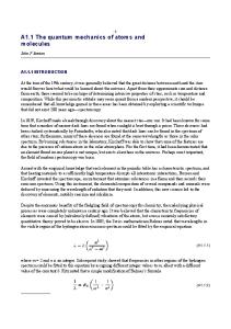
of absorption with chemical reaction is the absorption of carbon dioxide from a flue gas with aqueous sodium hydroxide. In this reaction, sodium carbonate is formed. This reaction is irreversible. However, continued absorption of the carbon dioxide with the sodium carbonate solution results in the formation of sodium acid carbonate. The latter can be decomposed upon heating to carbon dioxide, water, and sodium carbonate and thus the sodium carbonate can be recycled. Types of equipment used for absorption include (1) a packed tower filled with packing material, absorbent liquid flowing down through the packing (designed to provide a maximum of contact surface), and gas flowing upward in a countercurrent fashion; (2) a spray tower in which the absorbing liquid is sprayed into essentially an empty tower with the gas flowing upward; (3) a tray tower containing bubble caps, sieve trays, or valve trays; (4) a falling-film absorber or wetted-wall column; and (5) stirred vessels. Packed towers are the most commonly used. A representative packed-type absorption tower is shown in Fig. 1. In addition to absorption efficiency, a primary concern of the tower designer is that of minimizing the pressure drop through the tower. The principal elements of pressure drop are shown at the right of the diagram. Important to efficiency of absorption and pressure drop is the type of packing used. As shown by Fig. 2, over the years numerous types of packing (mostly ceramic) have been developed to meet a wide variety of operating parameters. A major objective is that of providing as much contact surface as is possible with a minimum of pressure drop. Where corrosion conditions permit, metal packing sometimes can be used. Of the packing designs illustrated, the berl saddles range in size from ovrtextstyle1over4 inch (6 millimeters) up to 2 inches (5 centimeters); raschig rings range from ovrtextstyle1over4 inch (6 millimeters) up to 4 inches (10 centimeters); lessing rings range from 1 inch (2.5 centimeters) up to 2 inches (5 centimeters); partition and spiral rings range from 3 inches (7.5 centimeters) up to 6 inches (15 centimeters). In operation, the absorbing liquid is pumped into the top of the column where it is distributed by means of a weir to provide uniform distribution of the liquid over the underlying packing. Gas enters at the base of the tower and flows upward (countercurrent with the liquid) and out the top of the tower. The liquid may or may not be recycled without regeneration, depending upon the strength of the absorbent versus the quantity of material (concentration) in the gas to be removed. In a continuous operation, of course, a point is reached where fresh absorbing liquid must be added. It is interesting to note that over 100,000 of the 14 -inch (6-millimeter) size packing shapes will be contained in each cubic foot (0.02832 cubic meter) of tower space if dense packing is desired.
Liquid in
Gas out
∆P(piping) out ∆Pdistributor
V-weir ∆Pexit
∆Ppacking (intrinsic)
Packing
∆Pentry
Support grillage Gas in
∆P(piping) in
Liquid out
Fig. 1. Section of representative packed absorption tower
Prym triangular packing
Divided rings
Raschig rings
Hollow ball packing
Partition rings
Berl saddle
Fig. 2. Types of packing used in absorption towers
In the purification of natural gas, the gas is fed into the bottom of an absorption tower where the gas is contacted countercurrently by a lean absorption oil. Hydrochloric acid is produced by absorbing gaseous hydrogen chloride in water, usually in a spray-type tower. Unreacted ammonia in the manufacture of hydrogen cyanide is absorbed in dilute sulfuric acid. In the production of nitric acid, ammonia is catalytically oxidized and the gaseous products are absorbed in water. The ethanolamines are widely used in scrubbing gases for removal of acid compounds. Hydrocarbon gases containing hydrogen sulfide can be scrubbed with monoethanolamine, which combines with it by salt formation and effectively removes it from the gas stream. In plants synthesizing ammonia, hydrogen and carbon dioxide are formed. The hydrogen can be obtained by countercurrently scrubbing the gas mixture in a packed or tray column with monoethanolamine which absorbs the carbon dioxide. The latter can be recovered by heating the monoethanolamine. In a nonliquid system, sulfur dioxide can be absorbed by dry cupric oxide on activated alumina, thus avoiding the disadvantages of a wet process. Sulfuric acid is produced by absorbing sulfur trioxide in weak acid or water. See also Coal; Ethanolamines; Chromatography; and Pollution (Air). Additional Reading Felder, T.D. and E.L. Garrett: Process Technology Systems, Pearson Education, Boston, MA, 2002. Geankoplis, C.J. and P.R. Toliver: Transport Processes and Separation Process Principles (Includes Unit Operations), 4th Edition, Prentice Hall Professional Technical Reference, Upper Saddle River, NJ, 2003. Thomas, W.J. and B. Crittenden: Adsorption Technology and Design, Elsevier Science & Technology Books, New York, NY, 2000. Yang, R.T.: Gas Separation by Adsorption Processes, Vol. 1, World Scientific Publishing Company, Inc., Riveredge, NJ, 2000.
ABSORPTION SPECTROSCOPY. An important technique of instrumental analysis involving measurement of the absorption of radiant energy by a substance as a function of the energy incident upon it. Adsorption processes occur throughout the electromagnetic spectrum, ranging from the γ region (nuclear resonance absorption of the Mossbauer effect) to the radio region (nuclear magnetic resonance). In practice, they are limited to those processes that are followed by the emission of radiant energy of greater intensity than that which was absorbed. All absorption process involve absorption of a photon by the substance being analyzed. If it loses the excess energy by emitting a photon of less energy than that absorbed, fluorescence or phosphorescence is said to occur, depending on the lifetime of the excited state. The emitted energy is normally studied. If the source of radiant energy and the absorbing species are in identical energy states (in resonance), the excess energy is often given up by the nondirectional emission of a photon whose energy is identical with the absorbed. Either adsorption or emission may be studied, depending upon the chemical and instrumental circumstances. If the emitted energy is studied, the term resonance fluorescence is often used. However, if the absorbing
ACETALDEHYDE TABLE 1.
species releases the excess energy in small steps by intermolecular collision or some other process, it is commonly understood that this phenomenon falls within the realm of absorption spectroscopy. The terms absorption spectroscopy, spectrophotometry, and absorptimetry are often used synonymously. Most absorption spectroscopy is done in the ultraviolet, visible, and infrared regions of the electromagnetic spectrum. See also Emission Spectroscopy; and Infrared Radiation. ABSORPTION SPECTRUM. The spectrum of radiation that has been filtered through a material medium. When white light traverses a transparent medium, a certain portion of it is absorbed, the amount varying, in general, progressively with the frequency of which the absorption coefficient is a function. Analysis of the transmitted light may, however, reveal that certain frequency ranges are absorbed to a degree out of all proportion to the adjacent regions; that is, with a distinct selectivity. These abnormally absorbed frequencies constitute, collectively, the “absorption spectrum” of the medium, and appear as dark lines or bands in the otherwise continuous spectrum of the transmitted light. The phenomenon is not confined to the visible range, but may be found to extend throughout the spectrum from the far infrared to the extreme ultraviolet and into the x-ray region. A study of such spectra shows that the lines or bands therein accurately coincide in frequency with certain lines or bands of the emission spectra of the same substances. This was formerly attributed to resonance of electronic vibrations, but is now more satisfactorily explained by quantum theory on the assumption that those quanta of the incident radiation which are absorbed are able to excite atoms or molecules of the medium to some (but not all) of the energy levels involved in the production of the complete emission spectrum. A very familiar example is the spectrum of sunlight, which is crossed by innumerable dark lines, the Fraunhofer lines, much has been learned about the constitution of the sun, stars, and other astronomical objects from the Fraunhofer lines. A noteworthy characteristic of selective absorption is found in the existence of certain anomalies in the refractive index in the neighborhood of absorption frequencies; discussed under Dispersion. See also Absorption Band; and Electromagnetic Spectrum. Additional Reading Baeyans, W.R.G., et al.: Luminescence Techniques in Chemical and Biochemical Analysis, in Practical Spectroscopy Series, Vol. 12, Marcel Dekker, New York, NY, 1991. Burgess, C. and D.G. Jones: Spectrophotometry, Luminescence and Colour: Science and Compliance: Papers Presented at the Second Joint Meeting of the Uv Spectrometry Group of the u, Elsevier Science, Ltd, New York, NY, 1995. Evans, N.J.: “Impedance Spectroscopy Reveals Materials Characteristics,” Adv. Mat. & Proc., 41 (November 1991). Ewing, G.W., Editor: Analytical Instrumentation Handbook, 2nd Edition Marcel Dekker, New York, NY, 1997. Grant, E.R. and R.G. Cooks: “Mass Spectrometry and Its Use in Tandem with Laser Spectroscopy,” Science, 61 (October 5, 1990). Robinson, J.W.: Atomic Spectroscopy, 2nd Edition Marcel Dekker, New York, NY, 1996. Van Grieken, R. and A. Markowicz: Handbook of X-Ray Spectrometry: Methods and Techniques, Marcel Dekker, New York, NY, 1992. Various: “Application Reviews (Chemical Instrumentation)” Analytical Chemistry (Special Issue), (June 15, 1991).
ABS RESINS (Acrylonitrile-Butadiene-Styrene). See Resins (Acrylonitrile-Butadiene-Styrene). ABUNDANCE. The relative amount (% by weight) of a substance in the earth’s crust, including the atmosphere and the oceans. (1)
The abundance of the elements in the earth’s crust is shown in Table 1. (2) The percentages of inorganic compounds in the earth’s crust, exclusive of water, are: (1) SiO2 (4) MgO
55 1.6
(2) Al2 O3 (5) Na2 O
15 1.6
(3) CaCO3 (6) K2 O
8.8 1.9
5
Rank 1 2 3 4 5 6 7 8 9 10 11 12 13 14 15 16
(3)
Element
% by wt.
Oxygen Silicon Aluminum Iron Calcium Sodium Potassium Magnesium Hydrogen Titanium Chlorine Phosphorus Manganese Carbon Sulfur Barium all others
49.2 25.7 7.5 4.7 3.4 2.6 2.4 1.9 0.9 0.6 0.2 0.1 0.1 0.09 0.05 0.05 0.51
The most abundant organic materials are cellulose and its derivatives, and proteins.
Note: In the universe as a whole, the most abundant element is hydrogen. ACARICIDE. A substance, natural or synthetic, used to destroy or control infestations of the animals making up Arachnida, Acarina, mainly mites and ticks, some forms of which are very injurious to both plants and livestock, including poultry. There are numerous substances that are effective both as acaricides and insecticides; others of a narrower spectrum are strictly acaricides. See also Insecticide; and Insecticide and Pesticide Technology. ACCELERATOR 1. A compound, usually organic, that greatly reduces the time required for vulcanization of natural and synthetic rubbers, at the same time improving the aging and other physical properties. See also Rubber (Natural). Organic accelerators invariably contain nitrogen, and many also contain sulfur. The latter type are called ultraaccelerators because of their greater activity. The major types include amines, guanidines, thiazoles, thiuram sulfides, and dithiocarbamates. The amines and guanidines are basic, the others acidic. The normal effective concentration of organic accelerators in a rubber mixture is 1% or less depending on the rubber hydrocarbon present. Zinc oxide is required for activation, and in the case of acidic accelerators, stearic acid is required. The introduction of organic accelerators in the early twenties was largely responsible for the successful development of automobile tires and mechanical products for engineering uses. A few inorganic accelerators are still used in low-grade products, e.g., lime, magnesium oxide, and lead oxide. 2. A compound added to a photographic developer to increase its activity, such as certain quaternary ammonium compounds and alkaline substances. 3. A particle accelerator. ACETALDEHYDE. [CAS: 75-07-0]. CH3 CHO, formula weight 44.05, colorless, odorous liquid, mp −123.5◦ C, bp 20.2◦ C, sp gr 0.783. Also known as ethanal, acetaldehyde is miscible with H2 O, alcohol, or ether in all proportions. Because of its versatile chemical reactivity, acetaldehyde is widely used as a commencing material in organic syntheses, including the production of resins, dyestuffs, and explosives. The compound also is used as a reducing agent, preservative, and as a medium for silvering mirrors. In resin manufacture, paraldehyde (CH3 CHO)3 sometimes is preferred because of its higher boiling and flash points. In tonnage production, acetaldehyde may be manufactured by (1) the direct oxidation of ethylene, requiring a catalytic solution of copper chloride plus small quantities of palladium chloride, (2) the oxidation of ethyl alcohol with sodium dichromate, and (3) the dry distillation of calcium acetate with calcium formate.
6
ACETAL GROUP
Acetaldehyde reacts with many chemicals in a marked manner, (1) with ammonio-silver nitrate (“Tollen’s solution”), to form metallic silver, either as a black precipitate or as an adherent mirror film on glass, (2) with alkaline cupric solution (“Fehling’s solution”) to form cuprous oxide, red to yellow precipitate, (3) with rosaniline (fuchsine, magenta), which has been decolorized by sulfurous acid (“Schiff’s solution”), the pink color of rosaniline is restored, (4) with NaOH, upon warming, a yellow to brown resin of unpleasant odor separates (this reaction is given by aldehydes immediately following acetaldehyde in the series, but not by formaldehyde, furfuraldehyde or benzaldehyde), (5) with anhydrous ammonia, to form aldehyde-ammonia CH3 · CHOH· NH2 , white solid, mp 97◦ C, bp 111◦ C, with decomposition, (6) with concentrated H2 SO4 , heat is evolved, and with rise of temperature, paraldehyde (C2 H4 O)3 or
CH3·CH
OCH(CH3) OCH(CH3)
O
colorless liquid bp 124◦ C, slightly soluble in H2 O, is formed, (7) with acids, below 0◦ C, forms metaldehyde (C2 H4 O)x, white solid, sublimes at about 115◦ C without melting but with partial conversion to acetaldehyde, (8) with dilute HCl or dilute NaOH, aldol, CH3 · CHOH· CH2 CHO slowly forms, (9) with phosphorus pentachloride, forms ethylidene chloride, CH3 · CHCl2 , colorless liquid, bp 58◦ C, (10) with ethyl alcohol and dry hydrogen chloride, forms acetal, 1,1-diethyoxyethane CH3 · CH(OC2 H5 )2 , colorless liquid, bp 104◦ C, (11) with hydrocyanic acid, forms acetaldehyde cyanohydrin, CH3 · CHOH· CN, readily converted into alphahydroxypropionic acid, CH3 · CHOH· COOH, (12) with sodium hydrogen sulfite, forms acetaldehyde sodium bisulfite, CH3 · CHOH· SO3 Na, white solid, from which acetaldehyde is readily recoverable by treatment with sodium carbonate solution, (13) with hydroxylamine hydrochloride forms acetaldoxime, CH3 · CH:NOH, white solid, mp 47◦ C, (14) with phenylhydrazine, forms acetaldehyde phenylhydrazone, CH3 · CH:N· NH· C6 H5 , white solid, mp 98◦ C, (15) with magnesium methyl iodide in anhydrous ether (“Grignard’s solution”), yields, after reaction with water, isopropyl alcohol, (CH3 )2 CHOH, a secondary alcohol, (16) with semicarbazide, forms acetaldehyde semicarbazone, CH3 · CH:N· NH· CO· NH2 , white solid, mp 162◦ C, (17) with chlorine, forms trichloroacetaldehyde (“chloral”), CCl3 · CHO, (18) with H2 S, forms thioacetaldehyde, CH3 · CHS or (CH3 · CHS)3 . Acetaldehyde stands chemically between ethyl alcohol on one hand—to which it can be reduced—and acetic acid on the other hand—to which it can be oxidized. These reactions of acetaldehyde, coupled with its ready formation from acetylene by mercuric sulfate solution as a catalyzer, open up a vast field of organic chemistry with acetaldehyde as raw material: acetaldehyde hydrogenated to ethyl alcohol; oxygenated to acetic acid, thence to acetone, acetic anhydride, vinyl acetate, vinyl alcohol. Acetaldehyde is also formed by the regulated oxidation of ethyl alcohol by such a reagent as sodium dichromate in H2 SO4 (chromic sulfate also produced). Reactions (1), (3), (14), and (16) above are most commonly used in the detection of acetaldehyde. See also Aldehydes. ACETAL GROUP. An organic compound of the general formula RCH(OR� )(OR�� ) is termed an acetal and is formed by the reaction of an aldehyde with an alcohol, usually in the presence of small amounts of acids or appropriate inorganic salts. Acetals are stable toward alkali, are volatile, insoluble in H2 O, and generally are similar structurally to ethers. Unlike ethers, acetals are hydrolyzed by acids into their respective aldehydes. H(R)CO + (HO · C2 H5 )2 −−−→ H(R)C(OC2 H5 )2 + H2 O. Representative acetals include: CH2 (OCH3 )2 , methylene dimethyl ether, bp 42◦ C; CH3 CH (OCH3 )2 , ethylidene dimethyl ether, bp 64◦ C; and CH3 CH(OC2 H5 )2 , ethylidene diethyl ether, bp 104◦ C. ACETAL RESINS. See Resins (Acetal). ACETATE DYE. One group comprises water insoluble azo or anthraquinone dyes that have be highly dispersed to make them capable of penetrating and dyeing acetate fibers. A second class consists of waterinsoluble amino azo dyes that are made water soluble by treatment with formaldehyde and bisulfite. After absorption by the fiber, the resulting sulfonic acids hydrolyze and regenerate the insoluble dyes. See also Dye and Dye Intermediates; and Dyes: Anthraquinone.
ACETATE FIBERS. See Fibers: Acetate. ACETATES. See Acetic Acid; Fibers: Acetate. ACETIC ACID. [CAS: 64-19-7]. CH3 COOH, formula weight 60.05, colorless, acrid liquid, mp 16.7◦ C, bp 118.1◦ C, sp gr 1.049. Also known as ethanoic acid or vinegar acid, this compound is miscible with H2 O, alcohol, and ether in all proportions. Acetic acid is available commercially in several concentrations. The CH3 COOH content of glacial acetic is approximately 99.7% with H2 O, the principal impurity. Reagent acetic acid generally contains 36% CH3 COOH by weight. Standard commercial aqueous solutions are 28, 56, 70, 80, 85, and 90% CH3 COOH. Acetic acid is the active ingredient in vinegar in which the content ranges from 4 to 5% CH3 COOH. Acetic acid is classified as a weak, monobasic acid. The three hydrogen atoms linked to one of the two carbon atoms are not replaceable by metals. In addition to the large quantities of vinegar produced, acetic acid in its more concentrated forms is an important high-tonnage industrial chemical, both as a reactive raw and intermediate material for various organic syntheses and as an excellent solvent. Acetic acid is required in the production of several synthetic resins and fibers, pharmaceuticals, photographic chemicals, flavorants, and bleaching and etching compounds. Early commercial sources of acetic acid included (1) the combined action of Bacterium aceti and air on ethyl alcohol in an oxidationfermentation process: C2 H5 OH + O2 −−−→ CH3 COOH + H2 O, the same reaction which occurs when weak alcoholic beverages, such as beer or wine, are exposed to air for a prolonged period and which turn sour because of the formation of acetic acid; and (2) the destructive distillation of wood. A number of natural vinegars still are made by fermentation and marketed as the natural product, but diluted commercially and synthetically produced acetic acid is a much more economic route to follow. The wood distillation route was phased out because of shortages of raw materials and the much more attractive economy of synthetic processes. The most important synthetic processes are (1) the oxidation of acetaldehyde, and (2) the direct synthesis from methyl alcohol and carbon monoxide. The latter reaction must proceed under very high pressure (approximately 650 atmospheres) and at about 250◦ C. The reaction takes place in the liquid phase and dissolved cobaltous iodide is the catalyst. CH3 OH + CO −−−→ CH3 COOH and CH3 OCH3 + H2 O + 2CO −−−→ 2CH3 COOH. The crude acid produced first is separated from the catalyst and then dehydrated and purified in an azeotropic distillation column. The final product is approximately 99.8% pure CH3 COOH. Acetic acid solution reacts with alkalis to form acetates, e.g., sodium acetate, calcium acetate; similarly, with some oxides, e.g., lead acetate; with carbonates, e.g., sodium acetate, calcium acetate, magnesium acetate; with some sulfides, e.g., zinc acetate, manganese acetate. Ferric acetate solution, upon boiling, yields a red precipitate of basic ferric acetate. Acetic acid solution attacks many metals, liberating hydrogen and forming acetate, e.g., magnesium, zinc, iron. Acetic acid is an important organic substance, with alcohols forming esters (acetates); with phosphorus trichloride forming acetyl chloride CH3 CO·Cl, which is an important reagent for transfer of the acetyl (CH3 CO−) group; forming acetic anhydride, also an acetyl reagent; forming acetone and calcium carbonate when passed over lime and a catalyzer (barium carbonate) or when calcium acetate is heated; forming methane (and sodium carbonate) when sodium acetate is heated with NaOH; forming mono-, di-, trichloroacetic (or bromoacetic) acids by reaction with chlorine (or bromine) from which hydroxy- and amino-, aldehydic-, dibasic acids, respectively, may be made; forming acetamide when ammonium acetate is distilled. Acetic acid dissolves sulfur and phosphorus, is an important solvent for organic substances, and causes painful wounds when it comes in contact with the skin. Normal acetates are soluble, basic acetates insoluble. The latter are important in their compounds with lead, and copper (“verdigris”). A large number of acetic acid esters are important industrially, including methyl, ethyl, propyl, butyl, amyl, and cetyl acetates; glycol mono- and diacetate; glyceryl mono-, di-, and triacetate; glucose pentacetate; and cellulose tri-, tetra-, and pentacetate. Acetates may be detected by formation of foul-smelling cacodyl (poisonous) on heating with dry arsenic trioxide. Other tests for acetate are the lanthanum nitrate test in which a blue or bluish-brown ring forms
ACETYLENE when a drop of 2.5% La(NO3 )3 solution, a drop of 0.01-N iodine solution, and a drop of 0.1% NH4 OH solution are added to a drop of a neutral acetate solution; the ferric chloride test, in which a reddish color is produced by the addition of 1-N ferric chloride solution to a neutral solution of acetate; and the ethyl acetate test, in which ethyl alcohol and H2 SO4 are added to the acetate solution and warmed to form a colorless solution. Additional Reading Agreda, V.H. and J. Zoeller: Acetic Acid and Its Derivatives, Marcel Dekker, Inc., New York, NY, 1992. Behrens, D.: DECHEMA Corrosion Handbook, Vol. 6, John Wiley & Sons, Inc., New York, NY. 1997. Dillon, C.P. and W.I. Pollock: Materials Selector for Hazardous Chemicals: Formic, Acetic and Other Organic Acids, Elsevier Science, New York, NY, 1998.
ACETOACTETIC ESTER CONDENSATION. A class of reactions occasioned by the dehydrating power of metallic sodium or sodium ethoxide on the ethyl esters of monobasic aliphatic acids and a few other esters. It is best known in the formation of acetoacetic ester: 2 CH3 · COOC2 H5 + 2 CH3 · COOC2 H5 + 2 Na −−−→ 2 CH3 · C(ONa) : CH · COOC2 H5 + 2 C2 H5 OH + H2 The actual course of the reaction is complex. By the action of acids the sodium may be eliminated from the first product of the reaction and the free ester obtained. This may exist in the tautomeric enol and keto forms (CH3 · COH:CH · COOC2 H5 and CH3 · CO · CH2 · COOC2 H5 ). On boiling ester with acids or alkalies it will split in two ways, the circumstances determining the nature of the main product. Thus, if moderately strong acid or weak alkali is employed, acetone is formed with very little acetic acid (ketone splitting). In the presence of strong alkalies, however, very little acetone and much acetic acid result (acid splitting). Derivatives of acetoacetic ester may be decomposed in the same fashion, and this fact is responsible for the great utility of this condensation in organic synthesis. This is also due to the reactivity of the · CH2 · group, which reacts readily with various groups, notably halogen compounds. Usually the sodium salt of the ester is used, and the condensation is followed by decarboxylation with dilute alkali, or deacylation with concentrated alkali. CH3 · CO · CHNa · COOC2 H5 + RI −−−→ CH3 · CO · CHR · COOC2 H5 + NaI
7
produced, followed by a breakdown of the acetate into acetone and calcium carbonate: CH3 · CO · O · Ca · OOC · CH3 −−−→ CH3 · CO · CH3 + CaCO3 ; and (2) by fermentation of starches, such as maize, which produce acetone along with butyl alcohol. Modern industrial processes include (3) the use of cumene as a chargestock, in which cumene first is oxidized to cumene hydroperoxide (CHP), this followed by the decomposition of CHP into acetone and phenol; and (4) by the direct oxidation of propylene, using air and catalysts. The catalyst solution consists of copper chloride and small amounts of palladium chloride. The reaction: CH3 CH = CH2 + 1/2 O2 −−−→ CH3 COCH3 . During the reaction, the palladium chloride is reduced to elemental palladium and HCl. Reoxidation is effected by cupric chloride. The cuprous chloride resulting is reoxidized during the catalyst regeneration cycle. The process is carried out under moderate pressure at about 100◦ C. Acetone reacts with many chemicals in a marked manner: (1) with phosphorus pentachloride, yields acetone chloride (CH3 )2 CCl2 , (2) with hydrogen chloride dry, yields both mesityl oxide CH3 COCH:C(CH3 )2 , liquid, bp 132◦ C, and phorone (CH3 )2 C:CHCOCH: C(CH3 )2 , yellow solid, mp 28◦ C, (3) with concentrated H2 SO4 , yields mesitylene C6 H3 (CH3 )3 (1,3,5), (4) with NH3 , yields acetone amines, e.g., diacetoneamine C6 H12 ONH, (5) with HCN, yields acetone cyanohydrin (CH3 )2 CHOH· CN, readily converted into alpha-hydroxy acid (CH3 )2 CHOH· COOH, (6) with sodium hydrogen sulfite, forms acetone-sodiumbisulfite (CH3 )2 COH· SO3 Na white solid, from which acetone is readily recoverable by treatment with sodium carbonate solution, (7) with hydroxylamine hydrochloride, forms acetoxime (CH3 )2 C:NOH, solid, mp 60◦ C, (8) with phenylhydrazine, yields acetonephenyl-hydrazone (CH3 )2 C:NNHC6 H5 · H2 O, solid, mp 16◦ C, anhydrous compound, mp 42◦ C, (9) with semicarbazide, forms acetonesemicarbazone (CH3 )C:NNHCONH2 , solid, mp 189◦ C, (10) with magnesium methyl iodide in anhydrous ether (“Grignard’s solution”), yields, after reaction with H2 O, trimethylcarbinol (CH3 )3 COH, a tertiary alcohol, (11) with ethyl thioalcohol and hydrogen chloride dry, yields mercaptol (CH3 )2 C(SC2 H5 )2 , (12) with hypochlorite, hypobromite, or hypoiodite solution, yields chloroform CHCl3 , bromoform CHBr3 or iodoform CHI3 , respectively, (13) with most reducing agents, forms isopropyl alcohol (CH3 )2 CHOH, a secondary alcohol, but with sodium amalgam forms pinacone (CH3 )2 COH· COH(CH3 )2 (14) with sodium dichromate and H2 SO4 , forms acetic acid CH3 COOH plus CO2 . When acetone vapor is passed through a tube at a dull red heat, ketene CH2 :CO and methane CH4 are formed. ACETYL CHLORIDE. See Chlorinated Organics.
H2 O
CH3 · CO · CHR · COOC2 H5 −−−−−→ CH3 · CO · CH2 R Dilutealkali
+ C2 H5 OH + CO2 2 H2 O
CH3 · CO · CHR · COOC2 H5 −−−−−−−−−→ HOOC · CH2 · R Concentrated alkali
+ C2 H5 OH + CH3 COOH ACETONE. [CAS: 67-64-1]. CH3 · CO· CH3 , formula weight 58.08, colorless, odorous liquid ketone, mp −94.6◦ C, bp 56.5◦ C, sp gr 0.792. Also known as dimethyl ketone or propanone, this compound is miscible in all proportions with H2 O, alcohol, or ether. Acetone is a very important solvent and is widely used in the manufacture of plastics and lacquers. For storage purposes, acetylene may be dissolved in acetone. A high-tonnage chemical, acetone is the starting ingredient or intermediate for numerous organic syntheses. Closely related, industrially important compounds are diacetone alcohol (DAA) CH3 · CO· CH2 · COH(CH3 )2 which is used as a solvent for cellulose acetate and nitrocellulose, as well as for various resins and gums, and as a thinner for lacquers and inking materials. Sometimes DAA is mixed with castor oil for use as a hydraulic brake fluid for which its physical properties are well suited, mp −54◦ C, bp 166◦ C, sp gr 0.938. A product known as synthetic methyl acetone is prepared by mixing acetone (50%), methyl acetate (30%), and methyl alcohol (20%) and is used widely for coagulating latex and in paint removers and lacquers. In older industrial processes, acetone is prepared (1) by passing the vapors of acetic acid over heated lime. In a first step, calcium acetate is
ACETYLENE. [CAS: 74-86-2]. CH:CH formula weight 26.04, mp −81.5◦ C, bp −84◦ C, sp gr 0.905 (air = 1.000). Sometimes referred to as ethyne, ethine, or gaseous carbon (92.3% of the compound is C), acetylene is moderately soluble in H2 O or alcohol, and exceptionally soluble in acetone (300 volumes of acetylene in 1 volume of acetone at 12 atmospheres pressure). The gas burns when ignited in air with a luminous sooty flame, requiring a specially devised burner for illumination purposes. An explosive mixture is formed with air over a wide range (about 3 to 80% acetylene), but safe handling is improved when the gas is dissolved in acetone. The heating value is 1455 Btu/ft3 (8.9 Cal/m3 ). Although acetylene still is used in a number of organic syntheses on an industrial scale, its use on a high-tonnage basis has diminished because of the lower cost of other starting materials, such as ethylene and propylene. Acetylene has been widely used in the production of halogen derivatives, acrylonitrile, acetaldehyde, and vinyl chloride. Within recent years, producers of acrylonitrile switched to propylene as a starting material. Commercially, acetylene is produced from the pyrolysis of naphtha in a two-stage cracking process. Both acetylene and ethylene are end products. The ratio of the two products can be changed by varying the naphtha feed rate. Acetylene also has been produced by a submerged-flame process from crude oil. In essence, gasification of the crude oil occurs by means of the flame, which is supported by oxygen beneath the surface of the oil. Combustion and cracking of the oil take place at the boundaries of the flame. The composition of the cracked gas includes about 6.3% acetylene and 6.7% ethylene. Thus, further separation and purification are required. Several years ago when procedures were developed for the
8
ACETYLENE SERIES
safe handling of acetylene on a large scale, J. W. Reppe worked out a series of reactions that later became known as “Reppe chemistry.” These reactions were particularly important to the manufacture of many high polymers and other synthetic products. Reppe and his associates were able to effect synthesis of chemicals that had been commercially unavailable. An example is the synthesis of cyclooctatetraene by heating a solution of acetylene under pressure in tetrahydrofuran in the presence of a nickel cyanide catalyst. In another reaction, acrylic acid was produced from CO and H2 O in the presence of a nickel catalyst: C2 H2 + CO + H2 O −−−→ CH2 : CH · COOH. These two reactions are representative of a much larger number of reactions, both those that are straight-chain only, and those involving ring closure. Acetylene reacts (1) with chlorine, to form acetylene tetrachloride C2 H2 Cl4 or CHCl2 · CHCl2 or acetylene dichloride C2 H2 Cl2 or CHCl:CHCl, (2) with bromine, to form acetylene tetrabromide C2 H2 Br4 or CHBr2 · CHBr2 or acetylene dibromide C2 H2 Br2 or CHBr:CHBr, (3) with hydrogen chloride (bromide, iodide), to form ethylene monochloride CH2 :CHCl (monobromide, monoiodide), and 1,1-dichloroethane, ethylidene chloride CH3 · CHCl2 (dibromide, diiodide), (4) with H2 O in the presence of a catalyzer, e.g., mercuric sulfate, to form acetaldehyde CH3 · CHO, (5) with hydrogen, in the presence of a catalyzer, e.g., finely divided nickel heated, to form ethylene C2 H4 or ethane C2 H6 , (6) with metals, such as copper or nickel, when moist, also lead or zinc, when moist and unpurified. Tin is not attacked. Sodium yields, upon heating, the compounds C2 HNa and C2 Na2 . (7) With ammoniocuprous (or silver) salt solution, to form cuprous (or silver) acetylide C2 Cu2 , dark red precipitate, explosive when dry, and yielding acetylene upon treatment with acid, (8) with mercuric chloride solution, to form trichloromercuric acetaldehyde C(HgCl)3 · CHO, precipitate, which yields with HCl acetaldehyde plus mercuric chloride. Additional Reading Stang, P.J. and F. Diederich: Modern Acetylene Chemistry, John Wiley & Sons, Inc., New York, NY, 1995.
ACETYLENE SERIES. A series of unsaturated hydrocarbons having the general formula Cn H2n−2 , and containing a triple bond between two carbon atoms. The series is named after the simplest compound of the series, acetylene HC:CH. In more modern terminology, this series of compounds is termed the alkynes. See also Alkynes. ACETYLSALICYLIC ACID. [CAS: 50-78-2]. C6 H4 (COOH)CO2 CH3 , formula wt, 180.06, mp 133.5◦ C, colorless, crystalline, slightly soluble in water, soluble in alcohol and ether, commonly known as aspirin, also called orthoacetoxybenzoic acid. The substance is commonly used as a relief for mild forms of pain, including headache and joint and muscle pain. The drug tends to reduce fever. Aspirin and other forms of salicylates have been used in large doses in acute rheumatic fever, but must be administered with extreme care in such cases by a physician. Commercially available aspirin is sometime mixed with other pain relievers as well as buffering agents. See also Aspirin; and Salicylic Acid and Related Compounds. ACHLORHYDRIA. Lack of hydrochloric acid in the digestive juices in the stomach. Hydrochloric acid helps digest food. The low pH of the normal stomach contents is a barrier to infection by various organisms and, where achlorhydria develops—particularly in malnutrition—it renders the patient more susceptible to infection, such as by Vibrio cholerae and Giardia lamblia. The condition is relatively common among people of about 50 years of age and older, affecting 15 to 20% of the population in this age group. The acid deficiency also occurs in about 30% of patients with adult onset-type of primary hypogamma-globulinemia. A well-balanced diet of easily digestible foods minimizes the discomforting effects of complete absence of hydrochloric acid in the stomach. The condition does not preclude full digestion of fats and proteins, the latter being attacked by intestinal and pancreatic enzymes. In rare cases, where diarrhea may result from achlorhydria, dilute hydrochloric acid may be administered by mouth. Where this causes an increase in discomfort or even pain, the use of dexamethasone or mucosal coating agents is preferred. Commonly, achlorhydria may not be accompanied by other diseases, but in some cases there is a connection. For example, achlorhydria is an abnormality that sometimes occurs with severe iron deficiency. Histalogfast achlorhydria, resulting from intrinsic factor deficiency in gastric juice, may be an indication of pernicious anemia. Hyperplastic polyps are often found in association with achlorhydria.
Excessive alcohol intake can also lead to achlorhydria and it is said that the resistance for cyanide poisoning of the Russian mystic, Rasputin, was attributable to that effect. The great amount of vodka that he consumed led to achlorhydria and thus the ingested potassium cyanide did not liberate lethal hydrocyanic gas, nor was the potassium salt absorbed through the stomach walls. Additional Reading Holt, P.R. and R.M. Russell: Chronic Gastritis-Achlorhydria in the Elderly, CRC Press, LLC., Boca Raton, FL, 1993.
ACID-BASE REGULATION (Blood). The hydrogen ion concentration of the blood is maintained at a constant level of pH 7.4 by a complex system of physico-chemical processes, involving, among others, neutralization, buffering, and excretion by the lungs and kidneys. This topic is sometimes referred to as acid-base metabolism. The clinical importance of acids and bases in life processes derives from several fundamental factors. (1) Most chemical reactions within the body take place in water solutions. The type and rate of such reactions is seriously affected by acid-base concentrations, of which pH is one indication. (2) Hydrogen ions are mobile charged particles and the distribution of such ions as sodium, potassium, and chloride in the cell environment are ultimately affected by hydrogen ion concentration (pH). (3) It also has been established that hydrogen ion concentration influences the three-dimensional configurations of proteins. Protein conformational changes affect the biochemical activity of proteins and thus can affect normal protein function. For example, enzymes, a particular class of proteins, exhibit optimal activity within a narrow range of pH. Most physiological activities, and especially muscular exercise, are accompanied by the production of acid, to neutralize which, a substantial alkali reserve, mainly in the form of bicarbonate, is maintained in the plasma, and so long as the ratio of carbon dioxide to bicarbonate remains constant, the hydrogen ion concentration of the blood does not alter. Any non-volatile acid, such as lactic or phosphoric, entering the blood reacts with the bicarbonate of the alkali reserve to form carbon dioxide, which is volatile, and which combines with hemoglobin by which it is transported to the lungs and eliminated by the processes of respiration. It will also be evident from this that no acid stronger than carbon dioxide can exist in the blood. The foregoing neutralizing and buffering effects of bicarbonate and hemoglobin are short-term effects; to insure final elimination of excess acid or alkali, certain vital reactions come into play. The rate and depth of respiration are governed by the level of carbon dioxide in the blood, through the action of the respiratory center in the brain; by this means the pulmonary ventilation rate is continually adjusted to secure adequate elimination of carbon dioxide. In the kidneys two mechanisms operate; ammonia is formed, whereby acidic substances in process of excretion are neutralized, setting free basic ions such as sodium to return to the blood to help maintain the alkali reserve. Where there is a tendency toward development of increased acidity in the blood, the kidneys are able selectively to reabsorb sodium bicarbonate from the urine being excreted, and to release into it acid sodium phosphate; where there is a tendency toward alkalemia, alkaline sodium phosphate is excreted, the hydrogen ions thus liberated are re-absorbed to restore the diminishing hydrogen ion concentration. See also Achlorhydria; Acidosis; Alkalosis; Blood; pH (Hydrogen Ion Concentration); and Potassium and Sodium (In Biological Systems). ACIDIC SOLVENT. A solvent which is strongly protogenic, i.e., which has a strong tendency to donate protons and little tendency to accept them. Liquid hydrogen chloride and hydrogen fluoride are acidic solvents, and in them even such normally strong acids as nitric acid do not exhibit acidic properties, since there are no molecules that can accept protons; but, on the contrary, behave to some extent as bases by accepting protons yielded by the dissociation of the HCl or the HF. See Acids and Bases. ACIDIMETRY. An analytical method for determining the quantity of acid in a given sample by titration against a standard solution of a base, or, more broadly, a method of analysis by titration where the end point is recognized by a change in pH (hydrogen ion concentration). See also Analysis (Chemical); pH (Hydrogen Ion Concentration); Titration (Potentiometric); and Titration (Thermometric). ACIDITY. The amount of acid present, expressed for a solution either as the molecular concentration of acid, in terms of normality, molality,
ACID RAIN etc., or the ionic concentration (hydrogen ions or protons) in terms of pH (the logarithm of the reciprocal of the hydrogen ion concentration). The acidity of a base is the number of molecules of monoatomic acid which one molecule of the base can neutralize. See Acids and Bases. ACID NUMBER. A term used in the analysis of fats or waxes to designate the number of milligrams of potassium hydroxide (KOH) required to neutralize the free fatty acids in 1 gram of substance. The determination is performed by titrating an alcoholic solution of the wax or fat with tenth or half-normal alkali, using phenolphthalein as indicator. ACIDOSIS. A condition of excess acidity (or depletion of alkali) in the body, in which acids are absorbed or formed in excess of their elimination, thus increasing the hydrogen ion concentration of the blood, exceeding the normal limit of 7.4. The acidity-alkalinity ratio in body tissue normally is delicately controlled by several mechanisms, notably the regulation of carbon dioxide-oxygen transfer in the lungs, the presence of buffer compounds in the blood, and the numerous sensing areas that are a part of the central nervous system. Normally, acidic materials are produced in excess in the body, this excess being neutralized by the presence of free alkaline elements, such as sodium occurring in plasma. The combination of sodium with excess acids produces carbon dioxide which is exhaled. Acidosis may result from: (1) severe exercise, leading to increased carbon dioxide content of the blood, (2) sleep, especially under narcosis, where the elimination of carbon dioxide is depressed, (3) heart failure, where there is diminished ventilation of carbon dioxide through the lungs, (4) diabetes and starvation, in which organic acids, such as β-hydroxybutyric and acetoacetic acids, accumulate, (5) kidney failure, in which the damaged kidneys cannot excrete acid radicals, and (6) severe diarrhea, in which there is loss of alkaline substances. Nausea, vomiting, and weakness sometimes may accompany acidosis. See also Acid-Base Regulation (Blood); Blood; and Potassium and Sodium (In Biological Systems). ACID RAIN. Acid rain can be simply described as rain that is more acidic than normal. Acid rain is a complicated problem. Caused by air pollution, acid rain’s spread and damage involve weather, chemistry, soil, and the life cycles of plants and animals on the land and in the water. Scientists have discovered that air pollution from the burning of fossil fuels is the major cause of acid rain. Acidic deposition, or acid rain, as it is commonly known, occurs when emissions of sulfur dioxide (SO2 ) and oxides of nitrogen (NOX ) react in the atmosphere with water, oxygen, and oxidants to form various acidic compounds. This mixture forms a mild solution of sulfuric acid and nitric acid. Sunlight increases the rate of most of these reactions. These compounds then fall to the earth in either wet form (such as rain, snow, and fog or dry form (such as gas and particles). About half of the acidity in the atmosphere falls back to earth through dry deposition as gases and dry particles. The wind blows these acidic particles and gases onto buildings, cars, homes, and trees. In some instances, these gases and particles can eat away the things on which they settle. Dry deposited gases and particles are sometimes washed from trees and other surfaces by rain. When that happens, the runoff water adds those acids to the acid rain, making the combination more acidic than the falling rain alone. The combination of acid rain plus dry deposited acid is called acid deposition. See Acid Deposition, which is discussed in more detail later in this entry. Prevailing winds transport the compounds, sometimes hundreds of miles, across state and national borders. Electric utility plants account for about 70 percent of annual SO2 emissions and 30 percent of NOX emissions in the United States. Mobile sources (transportation) also contribute significantly to NOX emissions. Overall, over 20 million tons of SO2 and NOX are emitted into the atmosphere each year. Acid rain causes acidification of lakes and streams and contributes to damage of trees at high elevations (for example, red spruce trees above 2,000 feet in elevation). In addition, acid rain accelerates the decay of building materials and paints, including irreplaceable buildings, statues, and sculptures that are part of our nation’s cultural heritage. Prior to falling to the earth, SO2 and NOX gases and their particulate matter derivatives, sulfates and nitrates, contribute to visibility degradation and impact public health. Implementation of the Acid Rain Program under the 1990 Clean Air Act Amendments will confer significant benefits on the nation. By reducing SO2
9
and NOX , many acidified lakes and streams will improve substantially so that they can once again support fish life. Visibility will improve, allowing for increased enjoyment of scenic vistas across our country, particularly in National Parks. Stress to the forests that populate the ridges of mountains from Maine to Georgia will be reduced. Deterioration of historic buildings and monuments will be slowed. Finally, reductions in SO2 and NOX will reduce sulfates, nitrates, and ground level ozone (smog), leading to improvements in public health. Surface Waters Acid rain primarily affects sensitive bodies of water, that is, those that rest atop soil with a limited ability to neutralize acidic compounds (called “buffering capacity”). Many lakes and streams examined in a National Surface Water Survey (NSWS) suffer from chronic acidity, a condition in which water has a constant low (acidic) pH level. The survey investigated the effects of acidic deposition in over 1,000 lakes larger than 10 acres and in thousands of miles of streams believed to be sensitive to acidification. Of the lakes and streams surveyed in the NSWS, acid rain has been determined to cause acidity in 75 percent of the acidic lakes and about 50 percent of the acidic streams. Several regions in the U.S. were identified as containing many of the surface waters sensitive to acidification. They include, but are not limited to, the Adirondacks, the mid-Appalachian highlands, the upper Midwest, and the high elevation West. In some sensitive lakes and streams, acidification has completely eradicated fish species, such as the brook trout, leaving these bodies of water barren. In fact, hundreds of the lakes in the Adirondacks surveyed in the NSWS have acidity levels indicative of chemical conditions unsuitable for the survival of sensitive fish species. Emissions from U.S. sources also contribute to acidic deposition in eastern Canada, where the soil is very similar to the soil of the Adirondack Mountains, and the lakes are consequently extremely vulnerable to chronic acidification problems. The Canadian government has estimated that 14,000 lakes in eastern Canada are acidic. Streams flowing over soil with low buffering capacity are equally as susceptible to damage from acid rain as lakes are. Approximately 580 of the streams in the Mid-Atlantic Coastal Plain are acidic primarily due to acidic deposition. The New Jersey Pine Barrens area endures the highest rate of acidic streams in the nation with over 90 percent of the streams acidic. Over 1,350 of the streams in the Mid-Atlantic Highlands (midAppalachia) are acidic, primarily due to acidic deposition. Many streams in that area have already experienced trout losses due to the rising acidity. Acidification is also a problem in surface water populations that were not surveyed in federal research projects. For example, although lakes smaller than 10 acres were not included in the NSWS, there are from one to four times as many of these small lakes as there are larger lakes. In the Adirondacks, the percentage of acidic lakes is significantly higher when it includes smaller lakes (26 percent) than when it includes only the target size lakes (14 percent). The acidification problem in both the United States and Canada grows in magnitude if “episodic acidification” (brief periods of low pH levels from snowmelt or heavy downpours) is taken into account. Lakes and streams throughout the United States, including high-elevation western lakes, are sensitive to episodic acidification. In the Mid-Appalachians, the MidAtlantic Coastal Plain, and the Adirondack Mountains, many additional lakes and streams become temporarily acidic during storms and snowmelt. Episodic acidification can cause large-scale “fish kills.” For example, approximately 70 percent of sensitive lakes in the Adirondacks are at risk of episodic acidification. This amount is over three times the amount of chronically acidic lakes. In the mid-Appalachians, approximately 30 percent of sensitive streams are likely to become acidic during an episode. This level is seven times the number of chronically acidic streams in that area. Acid rain control will produce significant benefits in terms of lowered surface water acidity. If acidic deposition levels were to remain constant over the next 50 years (the time frame used for projection models), the acidification rate of lakes in the Adirondacks that are larger than 10 acres would rise by 50 percent or more. Scientists predict, however, that the decrease in SO2 emissions required by the Acid Rain Program will significantly reduce acidification due to atmospheric sulfur. Without the reductions in SO2 emissions, the proportions of aquatic systems in sensitive ecosystems that are acidic would remain high or dramatically worsen. The impact of nitrogen on surface waters is also critical. Nitrogen plays a significant role in episodic acidification and new research recognizes
10
ACID RAIN
the importance of nitrogen in long-term chronic acidification as well. Furthermore, the adverse impact of atmospheric nitrogen deposition on estuaries and other large bodies of water may be significant. For example, 30 to 40 percent of the nitrogen in the Chesapeake Bay comes from atmospheric deposition. Nitrogen is an important factor in causing eutrophication (oxygen depletion) of water bodies. Forests Acid rain has been implicated in contributing to forest degradation, especially in high-elevation spruce trees that populate the ridges of the Appalachian Mountains from Maine to Georgia, including national park areas such as the Shenandoah and Great Smoky Mountain national parks. Acidic deposition seems to impair the trees’ growth in several ways; for example, acidic cloud water at high elevations may increase the susceptibility of the red spruce to winter injury. There also is a concern about the impact of acid rain on forest soils. There is good reason to believe that long-term changes in the chemistry of some sensitive soils may have already occurred as a result of acid rain. As acid rain moves through the soils, it can strip away vital plant nutrients through chemical reactions, thus posing a potential threat to future forest productivity. Visibility Sulfur dioxide emissions lead to the formation of sulfate particles in the atmosphere. Sulfate particles account for more than 50 percent of the visibility reduction in the eastern part of the United States, affecting our enjoyment of national parks, such as the Shenandoah and the Great Smoky Mountains. The Acid Rain Program is expected to improve the visual range in the eastern U.S. by 30 percent. Based on a study of the value national park visitors place on visibility, the visual range improvements expected at national parks of the eastern United States due to the Acid Rain Program’s SO2 reductions will be worth a billion dollars by the year 2010. In the western part of the United States, nitrogen and carbon also play roles, but sulfur has been implicated as an important source of visibility impairment in many of the Colorado River Plateau national parks, including the Grand Canyon, Canyonlands, and Bryce Canyon. Materials Acid rain and the dry deposition of acidic particles are known to contribute to the corrosion of metals and deterioration of stone and paint on buildings, cultural objects, and cars. The corrosion seriously depreciates the objects’ value to society. Dry deposition of acidic compounds can also dirty buildings and other structures, leading to increased maintenance costs. To reduce damage to automotive paint caused by acid rain and acidic dry deposition, some manufacturers use acid-resistant paints, at an average cost of $5 for each new vehicle (or a total of $61 million per year for all new cars and trucks sold in the U.S.) The Acid Rain Program will reduce damage to materials by limiting SO2 emissions. The benefits of the Acid Rain Program are measured, in part, by the costs now paid to repair or prevent damage—the costs of repairing buildings, using acid-resistant paints on new vehicles, plus the value that society places on the details of a statue lost forever to acid rain. Health Based on health concerns, SO2 has historically been regulated under the Clean Air Act. Sulfur dioxide interacts in the atmosphere to form sulfate aerosols, which may be transported long distances through the air. Most sulfate aerosols are particles that can be inhaled. In the eastern United States, sulfate aerosols make up about 25 percent of the inhalable particles. According to recent studies at Harvard and New York Universities, higher levels of sulfate aerosols are associated with increased morbidity (sickness) and mortality from lung disorders, such as asthma and bronchitis. By lowering sulfate aerosol levels, the Acid Rain Program will reduce the incidence and the severity of asthma and bronchitis. When fully implemented by the year 2010, the public health benefits of the Acid Rain Program will be significant, due to decreased mortality, hospital admissions, and emergency-room visits. Decreases in nitrogen oxide emissions are also expected to have positive health effects by reducing the nitrate component of inhalable particulates and reducing the nitrogen oxides available to react with volatile organic compounds (VOCs) and form ozone. Ozone impacts on human health include a number of morbidity and mortality risks associated with lung disorders.
Automotive Coatings Since about 1990, reports of damage to automotive coatings have increased. The reported damage typically occurs on horizontal surfaces and appears as irregularly shaped, permanently etched areas. The damage can best be detected under fluorescent lamps, can be most easily observed on dark colored vehicles, and appears to occur after evaporation of a moisture droplet. In addition, some evidence suggests damage occurs most frequently on freshly painted vehicles. Usually the damage is permanent; once it has occurred, the only solution is to repaint. The general consensus within the auto industry is that the damage is caused by some form of environmental fallout. “Environmental fallout,” a term widely used in the auto and coatings industries, refers to damage caused by air pollution (e.g., acid rain), decaying insects, bird droppings, pollen, and tree sap. The results of laboratory experiments and at least one field study have demonstrated that acid rain can scar automotive coatings. Furthermore, chemical analyses of the damaged areas of some exposed test panels showed elevated levels of sulfate, implicating acid rain. The popular term “acid rain” refers to both wet and dry deposition of acidic pollutants that may damage material surfaces, including auto finishes. These pollutants, which are released when coal and other fossil fuels are burned react with water vapor and oxidants in the atmosphere and are chemically transformed into sulfuric and nitric acids. The acidic compounds then may fall to earth as rain, snow, fog, or may join dry particles and fall as dry deposition. Automotive coatings may be damaged by all forms of acid rain, including dry deposition, especially when dry acidic deposition is mixed with dew or rain. However, it has been difficult to quantify the specific contribution of acid rain to paint finish damage relative to damage caused by other forms of environmental fallout, by the improper application of paint or by deficient paint formulations. According to coating experts, trained specialists can differentiate between the various forms of damage, but the best way of determining the cause of chemically induced damage is to conduct a detailed, chemical analysis of the damaged area. Because evaporation of acidic moisture appears to be a key element in the damage, any steps taken to eliminate its occurrence on freshly painted vehicles may alleviate the problem. The steps include frequent washing followed by hand drying, covering the vehicle during precipitation events, and use of one of the protective coatings currently on the market that claim to protect the original finish. (However, data on the performance of these coatings are not yet sufficient.) The auto and coatings industries are fully aware of the potential damage and are actively pursuing the development of coatings that are more resistant to environmental fallout, including acid rain. The problem is not a universal one—it does not affect all coatings or all vehicles even in geographic areas known to be subject to acid rain, which suggests that technology exists to protect against this damage. Until that technology is implemented to protect all vehicles or until acid deposition is adequately reduced, frequent washing and drying and covering the vehicle appear to be the best methods to minimize acid rain damage. Acid Deposition Sulfur and nitrogen oxides are emitted into the atmosphere primarily from the burning of fossil fuels. These emissions react in the atmosphere to form compounds that are transported long distances and are subsequently deposited in the form of pollutants such as particulate matter (sulfates and nitrates), SO2 , NO2 , nitric acid and when reacted with volatile organic compounds (VOCs) form ozone. The effects of atmospheric deposition include acidification of lakes and streams, nutrient enrichment of coastal waters and large river basins, soil nutrient depletion and decline of sensitive forests, agricultural crop damage, and impacts on ecosystem biodiversity. Toxic pollutants and metals also can be transported and deposited through atmospheric processes. Both local and long-range emission sources contribute to atmospheric deposition. Total atmospheric deposition is determined using both wet and dry deposition measurements. Although the term “acid rain” is widely recognized, the dry deposition portion ranges from 20 to 60 percent of total deposition. The United States Environmental Protection agency (EPA) is required by several Congressional and other mandates to assess the effectiveness of air pollution control efforts. These mandates include Title IX of the Clean Air Act Amendments (CAAA), the National Acid Precipitation Assessment Program (NAPAP), the Government Performance and Results
ACID RAIN Act, and the U.S. Canada Air Quality Agreement. One measure of effectiveness of these efforts is whether sustained reductions in the amount of atmospheric deposition over broad geographic regions are occurring. However, changes in the atmosphere happen very slowly and trends are often obscured by the wide variability of measurements and climate. Many years of continuous and consistent data are required to overcome this variability, making long-term monitoring networks especially critical for characterizing deposition levels and identifying relationships among emissions, atmospheric loadings, and effects on human health and the environment. For wet and dry deposition, these studies typically include measurement of concentration levels of key chemical components as well as precipitation amounts. For dry deposition, analyses also must include meteorological measurements that are used to estimate rate of the actual deposition, or “flux.” Data representing total deposition loadings (e.g., total sulfate or nitrate) are what many environmental scientists use for integrated ecological assessments. Primary Atmospheric Deposition Monitoring Networks The National Atmospheric Deposition Program (NADP) and the Clean Air Status and Trends Network (CASTNET), described in detail below, were developed to monitor wet and dry acid deposition, respectively. Monitoring site locations are predominantly rural by design to assess the relationship between regional pollution and changes in regional patterns in deposition. CASTNET also includes measurements of rural ozone and the chemical constituents of PM2.5 . Rural monitoring sites of NADP and CASTNET provide data where sensitive ecosystems are located and provide insight into natural background levels of pollutants where urban influences are minimal. These data provide needed information to scientists and policy analysts to study and evaluate numerous environmental effects, particularly those caused by regional sources of emissions for which longrange transport plays an important role. Measurements from these networks are also important for understanding non-ecological impacts of air pollution such as visibility impairment and damage to materials, particularly those of cultural and historical importance. National Atmospheric Deposition Network The NADP was initiated in the late 1970s as a cooperative program between federal and state agencies, universities, electric utilities, and other industries to determine geographical patterns and trends in precipitation chemistry in the United States. Collection of weekly wet deposition samples began in 1978. The size of the NADP Network grew rapidly in the early 1980s when the major research effort by the NAPAP called for characterization of acid deposition levels. At that time, the network became known as the NADP/NTN (National Trends Network). By the mid-1980s, the NADP had grown to nearly 200 sites, where it stands today, as the longest running national deposition monitoring network. The NADP analyzes the constituents important in precipitation chemistry, including those affecting rainfall acidity and those that may have ecological effects. The Network measures sulfate, nitrate, hydrogen ion (measure of acidity), ammonia, chloride, and base cations (calcium, magnesium, potassium). To ensure comparability of results, laboratory analyses for all samples are conducted by the NADP’s Central Analytical Lab at the Illinois State Water Survey. A new subnetwork of the NADP, the Mercury Deposition Network (MDN) measures mercury in precipitation.
ž ž
ž
weekly average atmospheric concentrations of sulfate, nitrate, ammonium, sulfur dioxide, and nitric acid.
hourly concentrations of ambient ozone levels. meteorological conditions required for calculating dry deposition rates.
Dry deposition rates are calculated using atmospheric concentrations, meteorological data, and information on land use, vegetation, and surface conditions. CASTNET complements the database complied by NADP. Because of the interdependence of wet and dry deposition, NADP wet deposition data are collected at all CASTNET sites. Together, these two long-term databases provide the necessary data to estimate trends and spatial patterns in total atmospheric deposition. National Oceanic and Atmospheric Administration (NOAA) also operates a smaller dry deposition network called Atmospheric Integrated Assessment Monitoring Network (AIRMoN) focused on addressing research issues specifically related to dry deposition measurement. Ozone Data Collection Network Ozone data collected by CASTNET are complementary to the larger ozone data sets gathered by the State and Local Air Monitoring Stations (SLAMS) and National Air Monitoring Stations (NAMS) networks. Most air-quality samples at SLAMS/NAMS sites are located in urban areas, while CASTNET sites are in rural locations. Hourly ozone measurements are taken at each of the 50 sites operated by EPA. Data from these sites provide information to help characterize ozone transport issues and ozone exposure levels. Integrated Monitoring, and AIRMoN The Atmospheric Integrated Research Monitoring Network is an atmospheric component to the overall national integrated monitoring initiative that is currently evolving. AIRMoN is a relatively new program, constructed by combining and building upon pre-existing specialized wet deposition and dry deposition monitoring networks, and with two specific goals: 1. To provide regular and timely reports on the atmospheric consequences of emission reductions, as imposed under the Clean Air Act Amendments. 2. To provide quantified information required to extend these observations of atmospheric effects to atmospheric deposition, both wet and dry. AIRMoN has two principal components: wet and dry deposition. All variables are measured in a manner that is designed to detect and properly attribute the benefits of emissions controls mandated under the Clean Air Act Amendments of 1990, and to reveal the actual deposition that occurred without fear of chemical (or other) contamination. It should be emphasized that conventional monitoring programs rely on statistical methods to extract small signals from imperfect and noisy data records. AIRMoN is designed to take a new step, that will remove much of the noise by integrating modern forecast technology into the monitoring process. ARL presently focuses its research attention on: ž ž
Clean Air Status and Trends Network The CASTNET provides atmospheric data on the dry deposition component of total acid deposition, ground-level ozone, and other forms of atmospheric pollution. CASTNET is considered the nation’s primary source for atmospheric data to estimate dry acidic deposition and to provide data on rural ozone levels. Used in conjunction with other national monitoring networks, CASTNET is used to determine the effectiveness of national emission control programs. Established in 1987, CASTNET now comprises over 70 monitoring stations across the United States. The longest data records are primarily at eastern sites. The majority of the monitoring stations are operated by EPA’s Office of Air and Radiation; however, approximately 20 stations are operated by the National Park Service in cooperation with EPA. Each CASTNET dry deposition station measures:
11
ž ž
ž
the measurement of precipitation chemistry with fine time resolution (AIRMoN-wet), the development of systems for measuring deposition, both wet and dry, the measurement of dry deposition using micrometeorological methods (AIRMoN-dry), the development of techniques for assessing air-surface exchange in areas (such as specific watersheds) where intensive studies are not feasible, and the extension of local measurements and knowledge to describe a real average exchange in numerical models.
Clean Air Act The overall goal is to achieve significant environmental and public health benefits through reductions in emissions of sulfur dioxide (SO2 ) and nitrogen oxides (NOX ), the primary causes of acid rain. To achieve this goal at the lowest cost to society, the program employs both traditional and innovative, market-based approaches for controlling air pollution. In addition, the program encourages energy efficiency and pollution prevention.
12
ACIDS AND BASES
Title IV of the Clean Air Act Amendments of 1990 calls for a 10 million ton reduction in annual emissions of sulfur dioxide (SO2 ) in the United States by the year 2010, which represents an approximately 40 percent reduction in anthropogenic emissions from 1980 levels. Implementation of Title IV is referred to as the Acid Rain Program; the primary motivation for this section of the Clean Air Act Amendments is to reduce acid precipitation and dry deposition. To achieve these reductions, the law requires a two-phase tightening of the restrictions placed on fossil-fuel-fired power plants. The Act also calls for a 2 million ton reduction in NOX emissions by the year 2000. A significant portion of this reduction will be achieved by coal-fired utility boilers that will be required to install low NOX burner technologies and to meet new emissions standards. Phase I began in 1995 and affects 263 units at 110 mostly coal-burning electric utility plants located in 21 eastern and midwestern states. An additional 182 units joined Phase I of the program as substitution or compensating units, bringing the total of Phase I affected units to 445. Emissions data indicate that 1995 SO2 emissions at these units nationwide were reduced by almost 40% below their required level. Phase II, which begins in the year 2000, tightens the annual emissions limits imposed on these large, higher emitting plants and also sets restrictions on smaller, cleaner plants fired by coal, oil, and gas, encompassing over 2,000 units in all. The program affects existing utility units serving generators with an output capacity of greater than 25 megawatts and all new utility units. See also Pollution (Air). Additional Reading Ellerman, A.D., R. Schmalensee, E.M. Bailey, et al.: Markets for Clean Air: The U.S. Acid Rain Program, Cambridge University Press, New York, NY, 2000. Hocking, C., J. Barber, J. Coonrod, et al.: Acid Rain, University of California Press, Berkeley, CA, 2000. Howells, G.P.: Acid Rain and Acid Waters, 2nd Edition, Prentice-Hall, Inc., Upper Saddle River, NJ, 1995. Hunt, K.: Changes in Global Environment-Acid Rain, Kendall/Hunt Publishing Company, Dubuque, IA, 1997. Hutterman, A. and D. Godbold: Effects of Acid Rain on Forest Processes, John Wiley & Sons, Inc., New York, NY, 1994. Kosobud, R.F., D.L. Schreder and H.M. Biggs: Emissions Trading: Environmental Policy’s New Approach, John Wiley & Sons, Inc., New York, NY, 2000. Morgan, S.: Acid Rain, Franklin Watts, Danbury, CT, 1999. Somerville, R.C.J.: The Forgiving Air: Understanding Environmental Change, University of California Press, Berkeley, CA, 1998.
Web References http://www.epa.gov/ United States Environmental Protection Agency. http://www.epa.gov/acidrain/ardhome.html United States Environmental Protection Agency Acid Rain Program. http://www.epa.gov/acidrain/links.htm United States Environmental Protection Agency Links. http://www.ec.gc.ca/acidrain/acidfact.html Environment Canada. http://www.epa.gov/airsdata/ State and Local Air Monitoring Stations (SLAMS) and National Air Monitoring Stations (NAMS) networks. http://www.arl.noaa.gov/ National Oceanic and Atmospheric Administration (NOAA). http://www.arl.noaa.gov/research/themes/aq.html#3 Atmospheric Integra ted Assessment Monitoring Network (AIRMoN).
ACIDS AND BASES. The conventional definition of an acid is that it is an electrolyte that furnishes protons, i.e., hydrogen ions, H+ . An acid is sour to the taste and usually quite corrosive. A base is an electrolyte that furnishes hydroxyl ions, OH− . A base is bitter to the taste and also usually quite corrosive. These definitions were formulated in terms of water solutions and, consequently, do not embrace situations where some ionizing medium other than water may be involved. In the definition of Lowry and Brnsted, an acid is a proton donor and a base is a proton acceptor. Acid-base theory is described later. Acidification is the operation of creating an excess of hydrogen ions, normally involving the addition of an acid to a neutral or alkaline solution until a pH below 7 is achieved, thus indicating an excess of hydrogen ions. In neutralization, a balance between hydrogen and hydroxyl ions is effected. An acid solution may be neutralized by the addition of a base; and vice versa. The products of neutralization are a salt and water. Some of the inorganic acids, such as hydrochloric acid, HCl, nitric acid, HNO3 , and sulfuric acid, H2 SO4 , are very-high-tonnage products
and are considered very important chemical raw materials. The most common inorganic bases (or alkalis) include sodium hydroxide, NaOH, and potassium hydroxide, KOH, and also are high-tonnage materials, particularly NaOH. Several classes of organic substances are classified as acids, notably the carboxylic acids, the amino acids, and the nucleic acids. These and the previously mentioned materials are described elsewhere in this volume. Principal theories of acids and bases have included: (1) ArrheniusOstwald theory, which was proposed soon after the concept of the ionization of chemical substances in aqueous solutions was generally accepted. (2) Much later (1923), J.N. Brønsted defined an acid as a source of protons and a base is an acceptor of protons. (3) T.M. Lowry, working in the same time frame as Brønsted, developed a similar concept and, over the years, the concept has been referred to in the literature as the LowryBrønsted theory. It will be noted that this theory altered the definition of an acid very little, continuing to emphasize the role of the hydrogen ion. However, the definition of a base was extended beyond the role of the hydroxyl ion to include a wide variety of uncharged species, such as ammonia and the amines. (4) In 1938, G.N. Lewis further broadened the definition of Lowry-Brønsted. Lewis defined an acid as anything that can attach itself to something with an unshared pair of electrons. The broad definition of Lewis creates some difficulties when one attempts to categorize Lewis acids and bases. R.G. Pearson (1963) suggested two main categories—hard and soft acids as well as hard and soft bases. These are described in more detail by Long and Boyd (1983). (5) In 1939, M. Usanovich proposed still another theory called the positive-negative theory, also developed in detail by Long and Boyd. In terms of the definition that an acid is a proton donor and a base is a proton acceptor, hydrochloric acid, water, and ammonia (NH3 ) are acids in the reactions + − −−− −− → HCl ← − H + Cl + − −− −− → H2 O − ← − H + OH + − −− −− → NH3 − ← − H + NH2
Note that this definition is different in at least two major respects from the conventional definition of an acid as a substance dissociating to give H+ in water. The Lowry-Brnsted definition states that for every acid there be a “conjugate” base, and vice versa. Thus, in the examples cited above, Cl− , OH− , and NH− -are the conjugate bases of HCl, H2 O, and NH3 . Furthermore, since the equations given above should more properly be written + − −−− −− → HCl + H2 O ← − H3 O + Cl + − −−− −− → H2 O + H2 O ← − H3 O + OH + − −−− −− → NH3 + H2 O ← − H3 O + NH2
It can be seen that every acid-base reaction involving transfer of a proton will involve two conjugate acid-base pairs, e.g., in the last equation NH3 and H3 O+ are the acids and NH2 − and H2 O the respective conjugate bases. On the other hand, in the reaction + − −−− −− → NH3 + H2 O ← − NH4 + OH
H2 O and NH4 − are the acids and NH3 and OH− the bases. In other reactions, e.g., Base1 Acid2 Acid1 Base2 − − −− −− → C2 H3 O2 − + H2 O ← − HC2 H3 O2 + OH −2 − − − → H HCO3 − + HCO3 − CO + CO ←−−− 2 3 3 +2 −−− −− → N2 H5 + + N2 H5 + + N2 H4 ← − N2 H6 + −− −− → H2 O + Cr(H2 O)6 +3 − + Cr(H2 O)5 OH2+ ← − N3 O the conjugate acids and bases are as indicated. The theory is not limited to the aqueous solution; for example, the following reactions can be considered in exactly the same light: Base 1 Acid 2 Acid 1 Base 2 + − −− −− → NH3 + HCl + Cl− ← − NH4 − + −−− −− → CH3 CO2 H + HF ← − CH3 CO2 H2 + F + − − − → H HF + HClO4 − F + ClO ←−−− 2 4 + − − − − → (CH3 )2 O + HI ←−−− (CH3 )2 OH + I + −− −− → C6 H6 + HSO3 F − + SO3 F− ← − C6 H7
ACIDULANTS AND ALKALIZERS (Foods) Acids may be classified according to their charge or lack of it. Thus, in the reactions cited above, there are “molecular” acids and bases, such as HCl, H2 CO3 , HClO4 , etc., and N2 H4 , (CH3 )2 O, C6 H6 , etc., and 2+ + also cationic acids and bases, such as H3 O+ , N2 H+ 5 , N2 H6 , NH4 , (CH3 )2 OH+ , etc., as well as anionic acids and bases, such as HCO3 − , Cl− , NH2 − , NH3 −2 etc. In a more general definition, Lewis calls a base any substance with a free pair of electrons that it is capable of sharing with an electron pair acceptor, which is called an acid. For example, in the reaction: (C2 H5 )2 O : +BF3 −−−→ (C2 H5 )2 O:BF3 the ethyl ether molecule is called a base, the boron trifluroide, an acid. The complex is called a Lewis salt, or addition compound. Acids are classified as monobasic, dibasic, tribasic, polybasic, etc., according to the number (one, two, three, several, etc.) of hydrogen atoms, replaceable by bases, contained in a molecule. They are further classified as (1) organic, when the molecule contains carbon; (1a) carboxylic, when the proton is from a—COOH group; (2) normal, if they are derived from phosphorus or arsenic, and contain three hydroxyl groups: (3) ortho, meta, or para, according to the location of the carboxyl group in relation to another substituent in a cyclic compound; or (4) ortho, meta, or pyro, according to their composition. Superacids. Although mentioned in the literature as early as 1927, superacids were not investigated aggressively until the 1970s. Prior to the concept of superacids, scientists generally regarded the familiar mineral acids (HF, HNO3 , H2 SO4 , etc.) as the strongest acids attainable. Relatively recently, acidities up to 1012 times that of H2 SO4 have been produced. In very highly concentrated acid solutions, the commonly used measurement of pH is not applicable. See also pH (Hydrogen Ion Concentration). Rather, the acidity must be related to the degree of transformation of a base with its conjugate acid. In the Hammett acidity function, developed by Hammett and Deyrup in 1932, H0 = pKBH+ − log
BH+ B
where pkBH+ is the dissociation constant of the conjugate acid (BH+ ), and BH+ /B is the ionization ratio, measurable by spectroscopic means (UV or NMR). In the Hammett acidity function, acidity is a logarithmic scale wherein H2 SO4 (100%) has an H0 of −11.9; and HF, an H0 of −11.0. As pointed out by Olah et al. (1979), “The acidity of a sulfuric acid solution can be increased by the addition of solutes that behave as − + −−− −− → acids in the system: HA + H2 SO4 ← − H3 SO4 + A . These solutes increase the concentration of the highly acidic H3 SO4 cation just as the addition of an acid to water increases the concentration of the oxonium ion. H3 O+ . Fuming sulfuric acid (oleum) contains a series of such acids, the polysulfuric acids, the simplest of which is disulfuric acid, H2 S2 O7 , which ionizes as a moderately strong acid in sulfuric acid: − − −−− −− → H2 S2 O7 + H2 SO4 ← − H3 SO4 + HS2 O7 . Higher polysulfuric acids, such as H2 S3 O10 and H2 S4 O13 , also behave as acids and appear somewhat stronger than H2 S2 O7 .” Hull and Conant in 1927 showed that weak organic bases (ketones and aldehydes) will form salts with perchloric acid in nonaqueous solvents. This results from the ability of perchloric acid in nonaqueous systems to protonate these weak bases. These early investigators called such a system a superacid. Some authorities believe that any protic acid that is stronger than sulfuric acid (100%) should be typed as a superacid. Based upon this criterion, fluorosulfuric acid and trifluoro-methanesulfonic acid, among others, are so classified. Acidic oxides (silica and silica-alumina) have been used as solid acid catalysts for many years. Within the last few years, solid acid systems of considerably greater strength have been developed and can be classified as solid superacids. Superacids have found a number of practical uses. Fluoroantimonic acid, sometimes called Magic Acid, is particularly effective in preparing stable, long-lived carbocations. Such substances are too reactive to exist as stable species in less acidic solvents. These acids permit the protonation of very weak bases. For example, superacids, such as Magic Acid, can protonate saturated hydrocarbons (alkanes) and thus can play an important role in the chemical transformation of hydrocarbons, including the processes of isomerization and alkylation. See also Alkylation; and Isomerization. Superacids also can play key roles in polymerization and in various organic syntheses involving dienone-phenol rearrangement, reduction, carbonylation, oxidation, among others. Superacids also play a role in
13
inorganic chemistry, notably in the case of halogen cations and the cations of nonmetallic elements, such as sulfur, selenium, and tellurium. Free Hydroxyl Radical. It is important to distinguish the free radical · OH and the OH− ion previously mentioned. The free radical is created by complex reactions of so-called “excited” oxygen with hydrogen as the result of exposure to solar ultraviolet light. The radical has been found to be an important factor in atmospheric and oceanic chemistry. The life span of the radical is but a second or two, during which time it reacts with numerous atmospheric pollutants in a scavenging (oxidizing) manner. For example, it reacts with carbon monoxide, as commonly encountered in atmospheric smog. It also reacts with sulfurous gases and with hydrocarbons, as may result from incomplete combustion processes or that have escaped into the atmosphere (because of their volatility) from various sources. Because of the heavy workload placed upon the hydroxyl radical through such “cleansing” reactions in the atmosphere, some scientists are concerned that the atmospheric content of · OH has diminished with increasing pollution, estimating the probable drop to be as much as 5–25% during the past three centuries since the start of the Industrial Revolution. Ironically, some of the very pollutants that are targets for reduction also are compounds from which the · OH radical is produced and, as they are reduced, so will the concentration of · OH be reduced. The fact that there is only one hydroxyl radical per trillion air molecules must not detract from its effectiveness as a scavenger. Scientists at the Georgia Institute of Technology have devised a mass spectrometric means for testing the various theories pertaining to the chemistry of · OH. The probable importance of · OH in the oceans also is being investigated. Researchers at Washington State University and the Brookhaven National Laboratory have confirmed the presence of · OH in seawater and now are attempting to measure its content quantitatively and to determine the sources of its formation. Dissolved organic matter is one highly suspected source. Tentatively, it has been concluded (using a method called flash photolysis) that · OH concentrations (as well as daughter radicals) range from 5 to 15 times higher in deep water than in open-ocean surface waters. This may indicate that · OH may have some impact on biota residing in deep water and may enhance the secondary production of bacterial growth, particularly in “carbon limited” oligotrophic waters, in upwelling waters, and in regions with high ultraviolet radiation. See also specific acids and bases, such as sulfuric acid and sodium hydroxide, in alphabetically arranged entries throughout this Encyclopedia. Additional Reading Lide, D.R., Editor: CRC Handbook of Chemistry and Physics, 84th Edition, CRC Press LLC, Boca Raton, FL, 2003. Long, F.A., and R.H. Boyd: “Acid and Bases,” in McGraw-Hill Encyclopedia of Chemistry, McGraw-Hill Companies, Inc., New York, NY, 1983. Olah, G.A., G.K. Surya Prakash, and J. Sommer: “Superacids,” Science, 205, 13–20 (1979). Parker, P.: McGraw Encyclopedia of Chemistry, McGraw-Hill Companies, Inc., New York, NY, 1993. Walling, C.: Fifty Years of Free Radicals (Profiles, Pathways, and Dreams); American Chemical Society, Washington, DC, 1994.
ACIDULANTS AND ALKALIZERS (Foods). Well over 50 chemical additives are commonly used in food processing or as ingredients of final food products, essentially to control the pH (hydrogen ion concentration) of the process and/or product. An excess of hydrogen ions, as contributed by acid substances, produces a sour taste, whereas an excess of hydroxyl ions, as contributed by alkaline substances, creates a bitter taste. Soft drinks and instant fruit drinks, for example, owe their tart flavor to acidic substances, such as citric acid. Certain candies, chewing gums, jellies, jams, and salad dressings are among the many other products where a certain degree of tartness contributes to the overall taste and appeal. Taste is only one of several qualities of a process or product that is affected by an excess of either of these ions. Some raw materials are naturally too acidic, others too alkaline—so that neutralizers must be added to adjust the pH within an acceptable range. In the dairy industry, for example, the acid in sour cream must be adjusted by the addition of alkaline compounds in order that satisfactory butter can be churned. Quite often, the pH may be difficult to adjust or to maintain after adjustment. Stability of pH can be accomplished by the addition of buffering agents that, within limits, effectively maintain the desired pH even when additional acid or alkali is added. For example, orange-flavored instant breakfast drink has just
14
ACIDULANTS AND ALKALIZERS (Foods)
enough “bite” from the addition of potassium citrate (a buffering agent) to regulate the tart flavor imparted by another ingredient, citric acid. In some instances, the presence of acids or alkalies assists mechanical processing operations in food preparation. Acids, for example, make it easier to peel fruits and tubers. Alkaline solutions are widely used in removing hair from animal carcasses. The pH values of various food substances cover a wide range. Plant tissues and fluids (about 5.2); animal tissues and fluids (about 7.0 to 7.5); lemon juice (2.0 to 2.2); acid fruits (3.0 to 4.5); fruit jellies (3.0 to 3.5). Acidulants commonly used in food processing include: Acetic acid (glacial), citric acid, fumaric acid, glucono delta-lactone, hydrochloric acid, lactic acid, malic acid, phosphoric acid, potassium acid tartrate, sulfuric acid, and tartaric acid. Alkalies commonly used include: Ammonium bicarbonate, ammonium hydroxide, calcium carbonate, calcium oxide, magnesium carbonate, magnesium hydroxide, magnesium oxide, potassium bicarbonate, potassium carbonate, potassium hydroxide, sodium bicarbonate, sodium carbonate, sodium hydroxide, and sodium sesquicarbonate. Among the buffers and neutralizing agents favored are: Adipic acid, aluminum ammonium sulfate, ammonium phosphate (di- or monobasic), calcium citrate, calcium gluconate, sodium acid pyrophosphate, sodium phosphate (di-, mono-, and tri-basic), sodium pyrophosphate, and succinic acid. See also Buffer (Chemical); and pH (Hydrogen Ion Concentration). Functions of Acidulants In the baking industry, acidulants and their salts control pH to inhibit spoilage by microbial actions to enhance the stability of foams (such as whipped egg albumin), to assist in leavening in order to achieve desired volume and flavoring, and to maximize the performance of artificial preservatives. A variety of the food acids previously mentioned is used. For example, citric acid traditionally has been favored by bakers for pie fillings. Baking powders (leavening agents) frequently will contain adipic acid, fumaric acid, and cream of tartar. Fumaric acid, in particular, has been the choice for leavening systems of cakes, pancakes, biscuits, waffles, crackers, cookies, and doughnuts. This acid also provides the desired characteristic flavor for sour rye bread—this eliminating fermentation of the dough to achieve desired flavor. Lactic acid and its salts sometimes are used as dough conditioners. Acidulants are used in the soft drink beverage industry for producing a tart taste, improving flavor balance, modifying the “sweetness” provided by sugar and other sweeteners, extending shelf life by reducing pH value of final product, and improving the performance of antimicrobial agents. Specific acidulants preferred vary with the type of beverage—i.e. carbonated, non-carbonated, dry (reconstituted by addition of water), and low-calorie products. In the production of confections and gelatin desserts, acidulants are used mainly for enhancing flavor, maintaining viscosity, and controlling gel formation. In confections, such as hard candies, acidulants are used to increase tartness and to enhance fruit flavors. Acidulants also contribute to the ease of manufacturing. In dairy products, acidulants, in addition to achieving many of the foregoing functions, also help to process the products. As an example, adipic acid improves the texture and melting characteristics of processed cheese and cheese foods, where pH control is very important. In fruit and vegetable processing, acidulants play somewhat different roles than previously described. These would include reducing process heating requirements through pH control, inactivating certain enzymes that reduce shelf life, and chelation of trace metals that may be present (through catalytic enzymatic oxidation). Citric acid is used widely in canned fruits, such as apricots, peaches, pears, cherries, applesauce, and grapes, to retain the firmness of the products during processing. The acid also provides a desirable tartness in the final products. In the processed meat field, citric acid, along with oxidants, is used to prevent rancidity in frankfurters and sausages. Sodium citrate is used in processing livestock blood, which is used to manufacture some sausages and pet foods. Acidulants and alkalizers, like other food additives, are controlled by regulatory bodies in most industrial nations. Some of the additives mentioned in this article are considered to be “Generally Regarded as Safe,” having a GRAS classification. These include acetic, adipic, citric, glucone delta lactone, lactic, malic, phosphoric, and tartaric acids. Others are covered by the Code of Federal Registration (FDA) in the United States. A very orderly and informative article (Dziezak 1990) is suggested as a source of detailed information on this topic.
Additional Reading Dziezak, J.D.: “Acidulants: Ingredients That Do More than Meet the Acid Test,” Food Techy., 76 (January 1990). Igoe, R.S.: Dictionary of Food Ingredients, Chapman & Hall, New York, NY, 1999. Kirk, R.E. and D.F. Othmer: Encyclopedia of Chemical Technology, 4th Edition, Vol. 6, John Wiley & Sons, New York, NY, 1993. Toledo, R.T.: Fundamentals of Food Process Engineering, 2nd Edition, Aspen Publishers, Inc., Gaithersburg, MD, 1999.
ACMITE-AEGERINE. Acmite is a comparatively rare rock-making mineral, usually found in nephelite syenites or other nephelite or leucitebearing rocks, as phonolites. Chemically, it is a soda-iron silicate, and its name refers to its sharply pointed monoclinic crystals. Bluntly terminated crystals form the variety aegerine, named for Aegir, the Icelandic sea god. Acmite has a hardness of 6 to 6.5, specific gravity 3.5, vitreous; color brown to greenish-black (aegerine), or red-brown to dark green and black (acmite). Acmite is synonymous with aegerine, but usually restricted to the long slender crystalline variety of brown color. The original acmite locality is in Greenland. Norway, the former U.S.S.R., Kenya, India, and Mt. St. Hilaire, Quebec, Canada furnish fine specimens. United States localities are Magnet Cove, Arkansas, and Libby, Montana, where a variety carrying vanadium occurs. ACREE’S REACTION. A test for protein in which a violet ring appears when concentrated sulfuric acid is introduced below a mixture of the unknown solution and a formaldehyde solution containing a trace of ferric oxide. ACROLEIN AND DERIVATIVES. Acrolein (2-propenal), C3 H4 O, is the simplest unsaturated aldehyde (CH2 =CHCHO). The primary characteristic of acrolein is its high reactivity due to conjugation of the carbonyl group with a vinyl group. More than 80% of the refined acrolein that is produced today goes into the synthesis of methionine. Much larger quantities of crude acrolein are produced as an intermediate in the production of acrylic acid. More than 85% of the acrylic acid produced worldwide is by the captive oxidation of acrolein. Acrolein is a highly toxic material with extreme lacrimatory properties. At room temperature acrolein is a liquid with volatility and flammability somewhat similar to acetone; but unlike acetone, its solubility in water is limited. Commercially, acrolein is always stored with hydroquinone and acetic acid as inhibitors. Special care in handling is required because of the flammability, reactivity, and toxicity of acrolein. The physical and chemical properties of acrolein are given in Table 1. Economic Aspects Presently, worldwide refined acrolein nameplate capacity is about 113,000 t/yr. Degussa has announced a capacity expansion in the United States by building a 36,000 t/yr acrolein plant in Theodore, Alabama to support their methionine business. The key producers of refined acrolein are Union Carbide (United States), Degussa (Germany), Atochem (France), and Daicel (Japan). Reactions and Derivatives Acrolein is a highly reactive compound because both the double bond and aldehydic moieties participate in a variety of reactions, including oxidation, reduction, reactions with alcohols yielding alkoxy propionaldehydes, TABLE 1. PROPERTIES OF ACROLEIN Property Physical properties molecular formula molecular weight specific gravity at 20/20◦ C boiling point, ◦ C at 101.3 kPaa Chemical properties autoignition temperature in air, ◦ C heat of combustion at 25◦ C, kJ/kgb a b
Value C 3 H4 O 56.06 0.8427 52.69 234 5383
To convert kPa to mm Hg, multiply by 7.5. To convert kJ to kcal, divide by 4.184.
ACRYLAMIDE POLYMERS
15
acrolein acetals, and alkoxypropionaldehyde acetals, addition of mercaptans yielding 3-methylmercaptopropionaldehyde, reaction with ammonia yielding β-picoline and pyridine, Diels-Alder reactions, and polymerization.
Manufacture The current routes to acrylamide are based on the hydration of inexpensive and readily available acrylonitrile (C3 H3 N, 2-propenenitrile, vinyl cyanide, VCN, or cyanoethene) See also Acrylonitrile.
Direct Uses of Acrolein Because of its antimicrobial activity, acrolein has found use as an agent to control the growth of microbes in process feed lines, thereby controlling the rates of plugging and corrosion. Acrolein at a concentration of M 2 . Presumably the relatively high tendency toward hydrolysis and complex ion formation of MO ions is related to the high concentration of charge on the metal atom. On the basis of increasing charge and decreasing ionic size, it could be expected that the degree of hydrolysis for each ionic type would increase with increasing atomic number. Metallic State. The actinide metals, like the lanthanide metals, are highly electropositive. They can be prepared by the electrolysis of molten salts or by the reduction of a halide with an electropositive metal, such as calcium or barium. Their physical properties are summarized in Table 3. Solid Compounds. Thousands of compounds of the actinide elements have been prepared, and the properties of some of the important binary compounds are summarized in Table 4. Crystal Structure and Ionic Radii. Crystal structure data have provided the basis for the ionic radii (coordination number = CN = 6). For both M3+ and M4 ions there is an actinide contraction, analogous to the lanthanide contraction, with increasing positive charge on the nucleus. As a consequence of the ionic character of most actinide compounds and of the similarity of the ionic radii for a given oxidation state, analogous compounds are generally isostructural. Absorption and Fluorescence Spectra. The absorption spectra of actinide and lanthanide ions in aqueous solution and in crystalline form contain narrow bands in the visible, near-ultraviolet, and near-infrared regions of the spectrum. TABLE 2. THE OXIDATION STATES OF THE ACTINIDE ELEMENTS 89 Ac
90 Th
91 Pa
3
(3) (3) 4 4 5
92 93 U Np 3 4 5 6
3 4 5 6 7
Atomic number and element 94 95 96 97 98 99 Pu Am Cm Bk Cf Es 3 4 5 6 (7)
(2) 3 4 5 6
3 4
3 4
(2) (2) 3 3 (4)
100 101 102 103 Fm Md No Lr 2 3
2 3
2 3
3
TABLE 3. PROPERTIES OF ACTINIDE METALS Element actinium thorium protactinium uranium neptunium plutonium americium curium berkelium californium einsteinium
Melting point, ◦ C 1100 ± 50 1750 1575 1132 637 ± 2 646 1173 1345 1050 900 ± 30 860 ± 30
Heat of vaporization, �Hv , kJ/mol (kcal/mol)
Boiling point, ◦ C
293 (70) 564 (130)
3850
446.4 (106.7) 418 (100) 333.5 (79.7) 230 (55) 386 (92.2)
3818 3900 3235 2011 3110
Transactinides The elements beyond the actinides in the periodic table can be termed the transactinides. These begin with the element having the atomic number 104 and extend, in principle, indefinitely. Although only seven such elements, numbers 104–110 were definitely known in 2003, (Rutherfordium 104, Dubnium 105, Seaborgium 106, Bohrium 107, Hassium 108, Meitnerium 109, and Darmstadtium 110), there are good prospects for the discovery of a number of additional elements just beyond number 110 or in the region of larger atomic numbers. They are synthesized by the bomunderlinedment of heavy nuclides with heavy ions. See also Chemical Elements. On the basis of the simplest projections it is expected that the half-lives of the elements beyond element 110 will become shorter as the atomic number is increased, and this is true even for the isotopes with the longest half-life for each element. Turning to consideration of electronic structure, upon which chemical properties must be based, modern high speed computers have made possible the calculation of such structures. The calculations show that elements 104 through 112 are formed by filling the 6d electron subshell, which makes them, as expected, homologous in chemical properties with the elements hafnium (Z = 72) through mercury (Z = 80). Elements 113 through 118 result from the filling of the 7p subshell and are expected to be similar to the elements thallium (Z = 81) through radon (Z = 86). It can be seen that elements in and near the island of stability based on element 114 can be predicted to have chemical properties as follows: element 114 should be a homologue of lead, that is, should be eka-lead; and element 112 should be eka-mercury, element 110 should be eka-platinum, etc. If there is an island of stability at element 126, this element and its neighbors should have chemical properties like those of the actinide and lanthanide elements. GLENN T. SEABORG University of California, Berkeley Additional Reading Hermann, G.: Superheavy Elements, International Review of Science, Inorganic Chemistry, Series 2, Vol. 8, Butterworths, London, and University Park Press, Baltimore, MD, 1975; G.T. Seaborg and W. Loveland, Contemp. Physics 28, 233 (1987). Herrmann, W.A.: Synthetic Methods of Organometallic and Inorganic Chemistry, Lanthanides and Actinides, Thieme Medical Publishers, New York, NY, 1997. Katz, J.J., G.T. Seaborg, and L.R. Moss, The Chemistry of the Actinide Elements, 2nd Edition, Chapman & Hall, New York, NY, 1986. Lide, D.R., Handbook of Chemistry and Physics, 84th Edition, CRC Press LLC, Boca Raton, FL, 2003. Marks, T.J.: “Actinide Organometallic Chemistry,” Science, 217, 989–997 (1982). Meyer, G. and L.R. Moss: Synthesis of Lanthanide and Actinide Compounds, Kluwer Academic Publishers, New York, NY, 1991. Seaborg, G.T.: The Transuranium Elements, Yale University Press, New Haven, CT, 1958. Seaborg, G.T. Ann. Rev. Nucl. Sci. 18, 53 (1968); O.L. Keller, Jr., and G.T. Seaborg, Ann. Rev. Nucl. Sci. 27, 139 (1977).
Web Reference http://www.acs.org/ American Chemical Society.
TABLE 4. PROPERTIES AND CRYSTAL STRUCTURE DATA FOR IMPORTANT ACTINIDE BINARY COMPOUNDS Compound AcH2 ThH2 Th4 H15 α-PaH3 β-PaH3 α-UH3 β-UH3 NpH2 NpH3 PuH2 PuH3 AmH2 AmH3 CmH2 CmH3 BkH2 BkH3 Ac2 O3 Pu2 O3 Pu2 O3 Am2 O3 Am2 O3 Cm2 O3 Cm2 O3 Cm2 O3 Bk2 O3 Bk2 O3 Bk2 O3 Cf2 O3 Cf2 O3 Cf2 O3 Es2 O3 Es2 O3 Es2 O3 ThO2 PaO2 UO2 NpO2 PuO2 AmO2 CmO2 BkO2 CfO2 Pa2 O5 Np2 O5 α-U3 O8 β-U3 O8 γ -UO3 AmCl2 CfCl2 AmBr2 CfBr2 ThI2 AmI2 CfI2 CfI2 AcF3 UF3 NpF3 PuF3 AmF3 CmF3 BkF3 BkF3 CfF3 CfF3 AcCl3 UCl3 NpCl3 PuCl3 AmCl3 CmCl3 BkCl3
Color black black black gray black ? black black black black black black black black black black black white ? black tan reddish brown white to faint tan white light green yellow-green yellowish brown pale green lime green pale green white white white white black brown to black apple green yellow-green to brown black black yellowish-brown black white dark brown black-green black-green orange black red-amber black amber gold black violet violet white black purple purple pink white yellow-green yellow-green light green light green white green green emerald green pink or yellow white green
Melting point, ◦ C
2085 2260
ca 3050 2875 2400
1150 (dec) 650 (dec)
ca 700
>1140(dec) 1425 1393 1406
835 ca 800 760 715 695 603
Symmetry
Space group or structure type
Density, g/mL
cubic tetragonal cubic cubic cubic cubic cubic cubic trigonal cubic trigonal cubic trigonal cubic trigonal cubic trigonal hexagonal cubic hexagonal hexagonal cubic hexagonal monoclinic cubic hexagonal monoclinic cubic hexagonal monoclinic cubic hexagonal monoclinic C2/m cubic cubic cubic cubic cubic cubic cubic cubic cubic cubic cubic monoclinic orthorhombic orthorhombic orthorhombic orthorhombic ? tetragonal tetragonal hexagonal monoclinic hexagonal rhombohedral trigonal trigonal trigonal trigonal trigonal trigonal orthorhombic trigonal orthorhombic trigonal hexagonal hexagonal hexagonal hexagonal hexagonal hexagonal hexagonal
fluorite (Fm3m) F4/mmm 143d Pm3n β-W Pm3n β-W (Pm3n) fluorite P3c1 fluorite P3c1 fluorite P3c1 fluorite P3c1 fluorite P3c1 La2 O3 (P3m1) Ia3 (Mn2 O3 ) La2 O3 La2 O3 Ia3 La2 O3 C2/m (Sm2 O3 ) Ia3 La2 O3 C2/m Ia3 La2 O3 C2/m Ia3 La2 O3 C2/m Ia3 fluorite fluorite fluorite fluorite fluorite fluorite fluorite fluorite fluorite fluorite-related P21 /c C2mm Cmcm Fddd Pbnm (PbCl2 )
8.35 9.50 8.25 10.87 10.58 11.12 10.92 10.41 9.64 10.40 9.61 10.64 9.76 10.84 10.06 11.57 10.44 9.19 10.20 11.47 11.77 10.57 12.17 11.90 10.80 12.47 12.20 11.66 12.69 12.37 11.39 12.7 12.4 11.79 10.00 10.45 10.95 11.14 11.46 11.68 11.92 12.31 12.46 11.14 8.18 8.39 8.32 7.80 6.78
SrBr2 (P4/n) SrBr2 P63 /mmc EuI2 (P21 /c) CdI2 (P3m1) CdCl2 (R3m) LaF3 (P3c1) LaF3 LaF3 LaF3 LaF3 LaF3 YF3 (Pnma) LaF3 YF3 LaF3 UCl3 (P63 /m) P63 /m UCl3 UCl3 UCl3 UCl3 UCl3
7.00 7.22 7.45 6.60 6.63 6.58 7.88 8.95 9.12 9.33 9.53 9.85 9.70 10.15 9.88 10.28 4.81 5.50 5.60 5.71 5.87 5.95 6.02 (continued overleaf )
25
26
ACTINIUM TABLE 4. (continued )
Compound α-CfCl3 β-CfCl3 EsCl3 AcBr3 UBr3 NpBr3 NpBr3 PuBr3 AmBr3 CmBr3 BkBr3 BkBr3 BkBr3 CfBr3 CfBr3 EsBr3 PaI3 UI3 NpI3 PuI3 AmI3 AmI3 CmI3 BkI3 CfI3 EsI3 ThF4 PaF4 UF4 NpF4 PuF4 AmF4 CmF4 BkF4 CfF4 α-ThCl4 β-ThCl4 PaCl4 UCl4 NpCl4 α-ThBr4 β-ThBr4 PaBr4 UBr4 NpBr4 ThI4 PaI4 UI4 PaF5 α-UF5 β-UF5 NpF5 PaCl5 α-UCl5 β-UCl5 α-PaBr5 β-PaBr5 UBr5 PaI5 UF6 NpF6 PuF6 UCl6 a
◦
Color
Melting point, C
Symmetry
Space group or structure type
Density, g/mL
green green white to orange white red green green green white to pale yellow pale yellow-green light green light green yellow green green green straw black black brown green pale yellow yellow white yellow red-orange amber to light yellow white reddish-brown green green brown tan light gray-green pale yellow-green light green white white greenish-yellow green red-brown white white orange-red brown dark red yellow black black white grayish white pale yellow
545
orthorhombic hexagonal hexagonal hexagonal hexagonal hexagonal orthorhombic orthorhombic orthorhombic orthorhombic monoclinic orthorhombic rhombohedral monoclinic rhombohedral monoclinic orthorhombic orthorhombic orthorhombic orthorhombic hexagonal orthorhombic hexagonal hexagonal hexagonal hexagonal monoclinic monoclinic monoclinic monoclinic monoclinic monoclinic monoclinic monoclinic monoclinic orthorhombic tetragonal tetragonal tetragonal tetragonal tetragonal tetragonal tetragonal monoclinic monoclinic monoclinic
TbCl3 (Cmcm) UCl3 UCl3 UBr3 (P63 /m) P63 /m UBr3 TbCl3 (Cmcm) TbCl3 TbCl3 TbCl3 AlCl3 (C2/m) TbCl3 FeCl3 (R3) AlCl3 FeCl3 AlCl3 TbCl3 (Cmcm) TbCl3 TbCl3 TbCl3 BiI3 (R3) PuBr3 BiI3 BiI3 BiI3 BiI3 UF4 (C2/c) UF4 C2/c UF4 UF4 UF4 UF4 UF4 UF4
6.07 6.12 6.20 5.85 6.55 6.65 6.67 6.72 6.85 6.85 5.604 6.95 5.54 5.673 5.77 5.62 6.69 6.76 6.82 6.92 6.35 6.95 6.40 6.02 6.05 6.18 6.20 6.38 6.73 6.86 7.05 7.23 7.36 7.55 7.57 4.12 4.60 4.72 4.89 4.96 5.94 5.77 5.90
yellow brown red-brown orange-brown brown black white orange reddish-brown dark green
730 681 625 ± 5
ca 950
1068 960 1037
770 590 518
519 464 556
306
64.02a 55 52 178
tetragonal tetragonal tetragonal tetragonal monoclinic monoclinic triclinic monoclinic monoclinic monoclinic orthorhombic orthorhombic orthorhombic orthorhombic hexagonal
UCl4 (I41 /amd) UCl4 I41 /amd UCl4 I41 /a UCl4 UCl4 2/c-/2/c-/P21 /n I42d I4/m I42d I4/m C2/c P21 /n P1 P21 /c P21 /n P21 /n Pnma Pnma Pnma P3m1
6.00
5.81 6.47 3.81
5.060 5.026 4.86 3.62
At 151.6 kPa; to convert kPa to atm, divide by 101.3.
ACTINIUM. [CAS: 7440-34-8]. Chemical element symbol Ac, at. no. 89, at. wt. 227 (mass number of the most stable isotope), periodic table group 3, classed in the periodic system as a higher homologue of lanthanum. The electronic configuration for actinium is 1s 2 2s 2 2p6 3s 2 3p6 3d 10 4s 2 4p6 4d 10 4f 14 5s 2 5p6 5d 10 6s 2 6p6 6d 1 7s 2 ˚ The ionic radius (Ac3+ ) is 1.11A.
Presently, 24 isotopes of actinium, with mass numbers ranging from 207 to 230, have been identified. All are radioactive. One year after the discovery of polonium and radium by the Curies, A. Debierne found an unidentified radioactive substance in the residue after treatment of pitchblende. Debierne named the new material actinium after the Greek word for ray. F. Giesel, independently in 1902, also found a radioactive material in the rare-earth extracts of pitchblende. He named
ACTIVATED SLUDGE this material emanium. In 1904, Debierne and Giesel compared the results of their experimentation and established the identical behavior of the two substances. Until formulation of the law of radioactive displacement by Fajans and Soddy about ten years later, however, actinium definitely could not be classed in the periodic system as a higher homologue of lanthanum. The isotope discovered by Debierne and also noted by Giesel was 227 Ac which has a half-life of 21.7 years. The isotope results from the decay of 235 U (AcU-actinouranium) and is present in natural uranium to the extent of approximately 0.715%. The proportion of Ac/U in uranium ores is estimated to be approximately 2.10−10 at radioactive equilibrium. O. Hahn established the existence of a second isotope of actinium in nature, 228 Ac, in 1908. This isotope is a product of thorium decay and logically also is referred to as meso-thorium, with a half-life of 6.13 hours. The proportion of mesothorium to thorium (MsTh2 /Th) in thorium ores is about 5.10−14 . The other isotopes of actinium were found experimentally as the result of bombarding thorium targets. The half-life of 10 days of 225 Ac is the longest of the artificially produced isotopes. Although occurring in nature as a member of the neptunium family, 225 Ac is present in extremely small quantities and thus is very difficult to detect. 227 Ac can be extracted from uranium ores where present to the extent of 0.2 mg/ton of uranium and it is the only isotope that is obtainable on a macroscopic scale and that is reasonably stable. Because of the difficulties of separating 227 Ac from uranium ores, in which it accompanies the rare earths and with which it is very similar chemically, fractional crystallization or precipitation of relevant compounds no longer is practiced. Easier separations of actinium from lanthanum may be effected through the use of ion-exchange methods. A cationic resin and elution, mainly with a solution of ammonium citrate or ammonium-a-hydroxyisobutyrate, are used. To avoid the problems attendant with the treatment of ores, 227 Ac now is generally obtained on a gram-scale by the transmutation of radium by neutron irradiation in the core of a nuclear reactor. Formation of actinium occurs by the following process: 226
β−
Ra(n, γ )227 Ra−−−→227 Ac
In connection with this method, the cross-section for the capture of thermal neutrons by radium is 23 barns (23 × 10−24 cm2 ). Thus, prolonged radiation must be avoided because the accumulation of actinium is limited by the reaction (σ = 500 barns): 227
Ac(n, γ )228 Ac(MsTh2 ) −−−→ 228 Th(RdTh)
In 1947, F. Hageman produced 1 mg actinium by this process and, for the first time, isolated a pure compound of the element. It has been found that when 25 g of RaCO3 (radium carbonate) are irradiated at a flux of 2.6 × 10¹⁴ ncm−2 s−1 for a period of 13 days, approximately 108 mg of 227 Ac (8 Ci) and 13 mg of 228 Th (11 Ci) will be yielded. In an intensive research program by the Centre d’Etude de l’Energie Nucl´eaire Belge, Union Mini`ere, carried out in 1970–1971, more than 10 g of actinium were produced. The process is difficult for at least two reasons: (1) the irradiated products are highly radioactive, and (2) radon gas, resulting from the disintegration of radium, is evolved. The methods followed in Belgium for the separation of 226 Ra, 227 Ac, and 228 Th involved the precipitation of Ra(NO3 )2 (radium nitrate) from concentrated HNO3 after which followed the elimination of thorium by adsorption on a mineral ion exchanger (zirconium phosphate) which withstand high levels of radiation without decomposition. Metallic actinium cannot be obtained by electrolytic means because it is too electropositive. It has been prepared on a milligram-scale through the reduction of actinium fluoride in a vacuum with lithium vapor at about 350◦ C. The metal is silvery white, faintly emits a blue-tinted light which is visible in darkness because of its radioactivity. The metal takes the form of a face-centered cubic lattice and has a melting point of 1050 ± 50◦ C. By extrapolation, it is estimated that the metal boils at about 3300◦ C. An amalgam of metallic actinium may be prepared by electrolysis on a mercury cathode, or by the action of a lithium amalgam on an actinium citrate solution (pH = 1.7 to 6.8). In chemical behavior, actinium acts even more basic than lanthanum (the most basic element of the lanthanide series). The mineral salts of actinium are extracted with difficulty from their aqueous solutions by means of an organic solvent. Thus, they generally are extracted as chelates with
27
trifluoroacetone or diethylhexylphosphoric acid. The water-insoluble salts of actinium follow those of lanthanum, namely, the carbonate, fluoride, fluosilicate, oxalate, phosphate, double sulfate of potassium. With exception of the black sulfide, all actinium compounds are white and form colorless solutions. The crystalline compounds are isomorphic. In addition to its close resemblance to lanthanum, actinium also is analogous to curium (Z = 96) and lawrencium (Z = 103), both of the group of trivalent transuranium elements. This analogy led G.T. Seaborg to postulate the actinide theory, wherein actinium begins a new series of rare earths which are characterized by the filling of the 5f inner electron shell, just as the filling of the 4f electron shell characterizes the Lanthanide series of elements. However, the first elements of the Actinide series differ markedly from those of actinium. Notably, there is a multiplicity of valences for which there is no equivalent among the lanthanides. See Chemical Elements for other properties of actinium. Mainly, actinium has been of interest from a scientific standpoint. However, 227 Ac has been proposed as a source of heat in space vehicles. It is interesting to note that the heat produced from the absorption of the radiation emitted by 1 g of actinium, when in equilibrium with its daughters, is 12,500 cal/hour. See also Actinide Contraction. Additional Reading Greenwood, N.N. and A. Earnshaw: Chemistry of the Elements, 2nd Edition, Butterworth-Heinemann, UK, 1997. Hageman, F.: “The Chemistry of Actinium”, in G.T. Seaborg and J.J. Katz (editors), The Actinide Elements, National Nuclear Energy Series, IV-14A, p. 14, McGrawHill, New York, NY, 1954. Katz, J.J., G.T. Seaborg, and L.R. Moss, The Chemistry of the Actinide Elements, 2nd Edition, Chapman & Hall, New York, NY, 1986. Lide, D.R., Handbook of Chemistry and Physics, 84th Edition, CRC Press LLC, Boca Raton, FL, 2003.
Web Reference http://www.acs.org/ American Chemical Society.
ACTINOLITE. The term for a calcium-iron-magnesium amphibole, the formula being Ca2 (Mg,Fe)5 Si8 O22 (OH)2 but the amount of iron varies considerably. It occurs as bladed crystals or in fibrous or granular masses. Its hardness is 5–6, sp gr 3–3.2, color green to grayish green, transparent to opaque, luster vitreous to silky or waxy. Iron in the ferrous state is believed to be the cause of its green color. Actinolite derives its name from the frequent radiated groups of crystals. Essentially it is an iron-rich tremolite; the division between the two minerals is quite arbitrary, with color the macroscopic definitive factor—white for tremolite, green for actinolite. Actinolite is found in schists, often with serpentine, and in igneous rocks, probably as the result of the alteration of pyroxene. The schists of the Swiss Alps carry actinolite. It is also found in Austria, Saxony, Norway, Japan, and Canada in the provinces of Quebec and Ontario. In the United States actinolite occurs in Massachusetts, Pennsylvania, Maryland, and as a zinc-manganese bearing variety in New Jersey. See also Amphibole; Tremolite; and Uralite. ACTINON. The name of the isotope of radon (emanation), which occurs in the naturally occurring actinium, series being, produced by alphadecay of actinium X, which is itself a radium isotope. Actinon has an atomic number of 86, a mass number of 219, and a half-life of 3.92 seconds, emitting an alpha particle to form polonium-215 (Actinium A). See also Chemical Elements; and Radioactivity. ACTIVATED SLUDGE. This is the biologically active sediment produced by the repeated aeration and settling of sewage and/or organic wastes. The dissolved organic matter acts as food for the growth of an aerobic flora. This flora produces a biologically active sludge which is usually brown in color and which destroys the polluting organic matter in the sewage and waste. The process is known as the activated sludge process. The activated sludge process, with minor variations, consists of aeration through submerged porous diffusers or by mechanical surface agitation, of either raw or settled sewage for a period of 2–6 hours, followed by settling of the solids for a period of 1–2 hours. These solids, which are made up of the solids in the sewage and the biological growths which
28
ACTIVATION (Molecular)
develop, are returned to the sewage flowing into the aeration tanks. As this cycle is repeated, the aerobic organisms in the sludge develop until there is 1000–3000 ppm of suspended sludge in the aeration liquor. After a while more of the active sludge is developed than is needed to purify the incoming sewage, and this excess is withdrawn from the process and either dried for fertilizer or digested anaerobically with raw sewage sludge. This anaerobic digestion produces a gas consisting of approximately 65% methane and 35% CO2 , and changes the water-binding properties so that the sludge is easier to filter or dry. The activated sludge is made up of a mixture of zoogleal bacteria, filamentous bacteria, protozoa, rotifera, and miscellaneous higher forms of life. The types and numbers of the various organisms will vary with the types of food present and with the length of the aeration period. The settled sludge withdrawn from the process contains from 0.6 to 1.5% dry solids, although by further settling it may be concentrated to 3–6% solids. Analysis of the dried sludge for the usual fertilizer constituents show that it contains 5–6% of slowly available N and 2–3% of P. The fertilizing value appears to be greater than the analysis would indicate, thus suggesting that it contains beneficial trace elements and growth-promoting compounds. Recent developments indicate that the sludge is a source of vitamin B12 , and has been added to mixed foods for cattle and poultry. The quality of excess activated sludge produced will vary with the food and the extent of oxidation to which the process is carried. In general, about 1 part sludge is produced for each part organic matter destroyed. Prolonged or over-aeration will cause the sludge to partially disperse and digest itself. The amount of air or more precisely oxygen that is necessary to keep the sludge in an active and aerobic condition depends on the oxygen demand of the sludge organisms, the quantity of active sludge, and the amount of food to be utilized. Given sufficient food and sufficient organisms to eat the food, the process seems to be limited only by the rate at which oxygen or air can be dissolved into the mixed liquor. This rate depends on the oxygen deficit, turbulence, bubble size, and temperature and at present is restricted by the physical methods of forcing the air through the diffuser tubers and/or mechanical agitation. In practice, the excess activated sludge is conditioned with 3–6% FeCl3 and filtered on vacuum filters. This reduces the moisture to about 80% and produces a filter cake which is dried in rotary or spray driers to a moisture content of less than 5%. It is bagged and sold direct as a fertilizer, or to fertilizer manufacturers who use it in mixed fertilizer. The mechanism of purification of sewage by the activated sludge is twofold i.e., (1) absorption of colloidal and soluble organic matter on the floc with subsequent oxidation by the organisms, and (2) chemical splitting and oxidation of the soluble carbohydrates and proteins to CO2 , H2 O, NH3 , NO2 , NO3 , SO4 , PO4 and humus. The process of digestion proceeds by hydrolysis, decarboxylation, deaminization and splitting of S and P from the organic molecules before oxidation. The process is applicable to the treatment of almost any type of organic waste waters which can serve as food for biological growth. It has been applied to cannery wastes, milk products wastes, corn products wastes, and even phenolic wastes. In the treatment of phenolic wastes a special flora is developed which thrives on phenol as food. W. D. HATFIELD Decatur, Illinois ACTIVATION (Molecular). When a molecule which is a Lewis base forms a coordinate bond with a metal ion or with a molecular Lewis acid (such as AlCl3 or BF3 ), its electronic density pattern is altered, and with this, the ease with which it undergoes certain reactions. In some instances the polarization that ensues is sufficient to lead to the formation of ions by a process of the type A:B: + M = A+ + :B:M− More commonly the molecule is polarized by coordination in such a manner that A bears a partial positive charge and B a partial negative charge in a complex A:B:M. Where M is a reducible or oxidizable metal ion, an electron-transfer process may result in which a free radical is generated from A:B: or its fragments and the metal assumes a different oxidation state. In any case the resulting species is often in a state in which it undergoes one or more types of chemical reaction much more readily.
Theoretical Basis The theoretical basis underlying these activation processes is in the description of the bonding which occurs between the ligand (Lewis base) and the coordination center. This consists of variable contributions from two types of bond. The first is from the sigma bond in which both the electrons in the bonding orbital come from the ligand. This kind of bonding occurs with ligands with available lone pairs (as NH3 , H2 O and their derivatives) and leads to a depletion of electronic charge from the substrate. The second is from the pi bond; here the electrons may come from the metal (if it is a transition metal with suitably occupied d orbitals) or from the ligand (where it has filled p orbitals or molecular orbitals of suitable symmetry). In this case the electronic shifts may partially compensate those arising from the sigma bond if the metal “backdonates” electrons to the ligand. Such shifts may also accentuate those of sigma bonding where ligand electrons are used for both bonds. It is generally found that the net drift of the electronic density is away from the ligand. Activation of Electrophiles The activation of electrophiles by coordination is a direct result of the weakening of the bond between the donor atom and the rest of the ligand molecule after the donor atom has become bonded to the coordination center. There is considerable evidence to support the claim that this bond need not be broken heterolytically prior to reaction as an electrophile. When this does not occur the literal electrophile is that portion of the ligand which bears a partial positive charge. In such a case the activation process can be more accurately represented by: δ+ δ−
A:B: + M = A:B:M Examples of this type of process are:
A:B: Cl:Cl: NC:Cl: RC:Cl: || O O2 N:Cl: O || RS:Cl: || O R:Cl:
+
M FeCl3 AlCl3 AlCl3 AlCl3 AlCl3 BF3
→
δ+ δ−
A:B:M Cl:Cl:FeCl3 NC:Cl:AlCl3 RC:Cl:AlCl3 || O O2 N:Cl:AlCl3 O || RS:Cl:AlCl3 || O R:Cl:BF3
The resultant electrophiles are effective attacking species and can be used to replace an aromatic hydrogen by the group A. When coordination is used to activate an electrophile which has additional donor groups not involved in the principal reaction, and if these are sufficiently effective as donors, they will react with the coordination centers initially added and stop the activation process. In these cases a larger amount of the Lewis acid must be added so that there is more than enough to complex with all the uninvolved donor groups. The extra reagent then provides the Lewis acid needed for the activation process. This is encountered in the Fries reaction and in Friedel-Crafts reactions where the substrate has additional coordination sites. This particular procedure is also used in the “swamping catalyst” procedure for the catalytic halogenation of aromatic compounds. The usual activation of carbon monoxide by coordination appears to involve complexes in which the carbon atom bonded to the metal is rendered slightly positive, and thus more readily attacked by electron rich species such as ethylenic or acetylenic linkages. An example is seen in the reaction of nickel carbonyl and aqueous acetylene, which results in the production of acrylic acid. Activation of Free Radicals The formation of free radicals results from a very similar process when the species M can be oxidized or reduced in a one-electron step with the
ACTIVITY COEFFICIENT resultant heterolytic splitting of the A:B bond. The basic reaction in an oxidation reaction of this sort is A:B: + M+x = A · +:B:M+x+1 where A and B may be the same or different. The most thoroughly characterized of these reactions is the one found with Fenton’s reagent: Fe2+ + HOOH = HO · +Fe (OH)2+ . The resultant hydroxyl radicals are effective in initiating many chain reactions. The number of metal ions and complexes which are capable of activating hydrogen peroxide in this manner is quite large and is determined in part by the redox potentials of the activator. Related systems in which free radicals are generated by the intervention of suitable metallic catalysts include many in which oxygen is consumed in autoxidations. Cobalt(II) compounds which act as oxygen carriers can often activate radicals in such systems by reactions of the type: Co(II)L + O2 = Co(III)L + O− 2 , etc. Processes of this sort have been used for catalytic oxidations and in cases where a complex with O2 is formed, the reversibility of the reaction has been studied as a potential process for separating oxygen from the atmosphere. Radical generating systems of this sort may be used for the initiation of many addition polymerization reactions including those of acrylonitrile and unsaturated hydrocarbons. The information on systems other than those derived from hydrogen peroxide is very meager. The activation of O2 by low oxidation states of plantinum has also been demonstrated in reactions such as Pt(P(C6 H5 )3 )3
2P(C6 H5 )3 + O2 −−−−−−−→ 2(C6 H5 )3 PO. Ligands such as ethylene are Lewis basesby virtue of the availability of the electrons of their pi bonds to external reagents and the coordination of unsaturated organic compounds to species such as Cu(I), Ag(I), Pd(II), and Pt(II) is a well established phenomenon. The coordination process with such ligands usually involves a considerable element of back bonding from the filled d orbitals of the metal ion. The coordination process activates olefins towards cis-trans isomerizations and attach by reagents such as hydrogen halides. Coordination to palladium(II) facilitates attach of olefins by water via a redox process as seen in the Smid reaction: PdCl2 + H2 C=CH2 + H2 O = Pd + CH3 CHO + 2HCl Pd + 2CuCl2 = 2CuCl + PdCl2 2HCl + 2CuCl + 12 O2 = 2CuCl2 + H2 O A similar reaction also occurs for carbon monoxide: Pd2+ + CO + H2 O = Pd + CO2 + 2H+ . Activation of nucleophiles by coordination, best exemplified by various complexes used as catalysts for hydrogenation, and coordination assistance to photochemical activation, may be similarly demonstrated. MARK M. JONES Vanderbilt University Nashville, Tennessee ACTIVATOR. 1. A substance that renders a material or a system reactive; commonly, a catalyst. 2. A special use of this term occurs in the flotation process, where an activator assists the action of the collector. 3. An impurity atom, present in a solid, that makes possible the effects of luminescence, or markedly increases their efficiency. Examples are copper in zinc sulfide, and thallium in potassium chloride. See also Enzyme. ACTIVE CENTER. Atoms which, by their position on a surface, such as at the apex of a peak, at a step on the surface or a kink in a step, or on the edge or corner of a crystal, share with neighboring atoms an abnormally small portion of their electrostatic field, and therefore have a large residual field available for catalytic activity or for adsorption.
29
ACTIVE DEPOSIT. The name given to the radioactive material that is deposited on the surface of any substance placed in the neighborhood of a preparation containing any of the naturally occurring radioactive chains (uranium, thorium, or actinium chains). This deposit results from deposition of the nongaseous products of the gaseous radon nuclides that have escaped from the parent substance. An active deposit can be concentrated on a negatively charged metal wire or surface placed in closed vessels containing the radon. See also Radioactivity. ACTIVITY COEFFICIENT. A fractional number which when multiplied by the molar concentration of a substance in solution yields the chemical activity. This term provides an approximation of how much interaction exists between molecules at higher concentrations. Activity coefficients and activities are most commonly obtained from measurements of vapor-pressure lowering, freezing-point depression, boiling-point elevation, solubility, and electromotive force. In certain cases, activity coefficients can be estimated theoretically. As commonly used, activity is a relative quantity having unit value in some chosen standard state. Thus, the standard state of unit activity for water, aw , in aqueous solutions of potassium chloride is pure liquid water at one atmosphere pressure and the given temperature. The standard state for the activity of a solute like potassium chloride is often so defined as to make the ratio of the activity to the concentration of solute approach unity as the concentration decreases to zero. In general, the activity coefficient of a substance may be defined as the ratio of the effective contribution of the substance to a phenomenon to the actual contribution of the substance to the phenomenon. In the case of gases the effective pressure of a gas is represented by the fugacity f and the actual pressure of the gas by P . The activity coefficient, γ , of the gas is given by γ = f/P . (1) One method of calculating fugacity and hence γ is based on the measured deviation of the volume of a real gas from that of an ideal gas. Consider the case of a pure gas. The free energy F and chemical potential µ changes with pressure according to the equation but by definition
dF = dµ = V dP .
(2)
dµ = V dP = RT d ln f
(3)
If the gas is ideal, the molal volume Vi is given by RT Vi = (4) P but for a nonideal gas this is not true. Let the molal volume of the nonideal gas be Vn and define the quantity α by the equation RT (5) α = Vi − Vn = − Vn P Then V of Eq. (2) is Vn of Eq. (5) and hence from Eq. (5) RT V = −α (6) P Therefore from Eqs. (2), (3), and (6) RT d ln f = dF = dµ = RT D ln P − α dP and
�
(7)
P
RT ln f = RT ln P −
α dP
(8)
0
Thus knowing PVT data for a gas it is possible to calculate f . The integral in Eq. (8) can be evaluated graphically by plotting α, the deviation of gas volume from ideality, versus P and finding the area under the curve out to the desired pressure. Also it may be found by mathematically relating α to P by an equation of state, or by using the method of least squares or other acceptable procedure the integral may be evaluated analytically for any value of P . The value of f at the desired value of P may thus be found and consequently the activity coefficient calculated. Other methods are available for the calculation of f and hence of γ , the simplest perhaps being the relationship P2 f = (9) Pi where Pi is the ideal and P the actual pressure of the gas.
30
ACTIVITY COEFFICIENT
In the case of nonideal solutions, we can relate the activity αA of any component A of the solution to the chemical potential µA of that component by the equation ◦�
µA = µA + RT ln aA =
◦� µA
+ RT ln γA XA
(10) (11)
where µ◦A is the chemical potential in the reference state where ai is unity and is a function of temperature and pressure only, whereas γA is a function of temperature pressure and concentration. It is necessary to find the conditions under which γA is unity in order to complete its definition. This can be done using two approaches—one using Raoult’s law which for solutions composed of two liquid components is approached as XA → 1; and two using Henry’s law which applies to solutions, one component of which may be a gas or a solid and which is approached at XA → 0. Here XA represents the mole fraction of component A. For liquid components using Raoult’s law �
γA → 1 as XA → 1
and the activity coefficients γ+ and γ− of the two charge types of ions are related to the molality, m, of the electrolyte and ion activities a+ and a− by the equations a+ a− γ+ = ; γ− = (21) pm qm Also the activity coefficient of the electrolyte is given by the equation p
In Eq. (15) aA is the activity or in a sense the effective mole fraction of component A in the solution. The activity aA of a component A in solution may be found by considering component A as the solvent. Then its activity at any mole fraction is the ratio of the partial pressure of the vapor of A in the solution to the vapor pressure of pure A. If B is the solute, its standard reference state is taken as a hypothetical B with properties which it possesses at infinite dilution. The equilibrium constant for the process B (gas) ↔ B (solution) is K=
asolution agas
(16) (17)
Since the gas is sufficiently ideal its activity agas is equivalent to its pressure P2 . Since the solution is far from ideal, the activity asolute of the liquid B is not equal to its mole fraction N2 in the solution. However, �
K = N2 /P2
(18)
and extrapolating a plot of this value versus N2 to N2 = 0 one obtains the ratio where the solution is ideal. This extrapolated value of K � is the true equilibrium constant K when the activity is equal to the mole fraction K = a2 /P2
γ = (γ+ × γ 2 )(1/1+2) = (γ+ × γ 2 )1/3
(23)
γ 3 = γ+ γ 2
(24)
also a = a+ × a 2 = (mγ+ )(2mγ− )2 = 4 m γ+ γ = 4 m γ 3
(19)
Thus a2 can be found. The methods involved in Eqs. (16) through (19) arrive at the activities directly and thus obviate the determination of the activity coefficient. However, from the determined activities and known mole fractions γ can be found as indicated in Eq. (15).
2
3
3
(25) (26)
Activity coefficients of ions are determined using electromotive force, freezing point, and solubility measurements or are calculated using the theoretical equation of Debye and H¨uckel. The solubility, s, of AgCl can be determined at a given temperature and the activity coefficient γ determined at that temperature from the solubility and the solubility product constant K. Thus
µ◦A �
Thus, for the solute in Eq. (11) is the chemical potential of the solute in a hypothetical standard state in which the solute at unit concentration has the properties which it has at infinite dilution. γA is the activity coefficient of component A in the solution and is given by the expression aA γA = (15) XA
(22)
In Eqs. (20), (21) and (22) p and q are numbers of positive and negative ions, respectively, in the molecule of electrolyte. In dilute solutions it is considered that ionic activities are equal for uni-univalent electrolytes, i.e., γ+ = γ − . Consider the case of BaCl2 . or
(14)
q
γ = (γ+ × γ− )(1/p+q)
(12)
Since the logarithmic term is zero in Eq. (11) under this limiting condition, µ◦A � is the chemical potential of pure component A at the temperature and pressure under consideration. For ideal solutions the activity coefficients of both components will be unity over the whole range of composition. The convention using Henry’s law is convenient to apply when it is impossible to vary the mole fraction of both components up to unity. Solvent and solute require different conventions for such solutions. As before, the activity of the solvent, usually taken as the component present in the higher concentration, is given by γA → 1 as XA → 0
In the case of ions the activities, a+ and a− of the positive and negative ions, respectively, are related to the activity, a, of the solute as a whole by the equation p q (20) a+ × a−
K = a + a − = γ+ c + γ− c −
(27)
where c+ and c− are the molar concentrations of the positive silver and negative chloride ions, respectively. The solubility s of the silver chloride is simply s = c+ = c− . The expression for K is then K = γ 2s2
(28)
and
K 1/2 (29) s By measuring the solubility, s, of the silver chloride in different concentration of added salt and extrapolating the solubilities to zero salt concentration, or better, to zero ionic strength, one obtains the solubility when γ = 1, and from Eq. (29) K can be found. Then γ can be calculated using this value of K and any measured solubility. Actually, this method is only applicable to sparingly soluble salts. Activity coefficients of ions and of electrolytes can be calculated from the Debye-H¨uckel equations. For a uni-univalent electrolyte, in water at 25◦ C, the equation for the activity coefficient of an electrolyte is √ (30) log γ = −0.509z+ z− µ γ =
where z+ and z− are the valences of the ion and µ is the ionic strength of the solution, i.e., (31) µ = 12 �ci zi2 where ci is the concentration and zi the valence of the ith type of ion. To illustrate a use of activity coefficients, consider the cell without liquid junction (32) Pt, H2 (g); HCl (m); AgCl, Ag for which the chemical reaction is 1 H (g) 2 2
+ AgCl (solid) = HCl (molality, m) + Ag (solid.)
(33)
The electromotive force, E, of this cell is given by the equation ◦
E=E − ◦
2.303 RT aHCl log nF PH2
= E − 0.05915 log m2 γ 2
(34)
ADDITIVE COLOR PROCESS where E ◦ is the standard potential of the cell, n is the number of electrons per ion involved in the electrode reaction (here n = 1), F is the coulombs per faraday, a (equal to m2 γ 2 ) is the activity of the electrolyte HCl, PH2 is the pressure (1 atm) and is equal to the activity of the hydrogen gas, and AgCl (solid) and Ag (solid) have unit activities. Transferring the exponents in front of the logarithmic term in Eq. (34), the equation can be written, ◦
E = E − 0.1183 log m − 0.1183 log γ
(35)
which by transposing the log m term to the left of the equation becomes ◦
E + 0.1183 log m = E − 0.1183 log γ
(36)
For extrapolation purposes, the extended form of the Debye-H¨uckel equation involving the molality of a dilute univalent electrolyte in water at 25◦ C is used: √ (37) log γ = −0.509 m + bm where b is an empirical constant. Substitution of log γ from Eq. (37) into Eq. (36) gives E + 0.1183 log m − 0.0602 m1/2 ◦
= E − 0.1183 bm
(38)
A plot of the left hand side of Eq. (38) versus m yields a practically straight line, the extrapolation of which to m = 0 gives E ◦ the standard potential of the cell. This value of E ◦ together with measured values of E at specified m values can be used to calculate γ for HCl in dilute aqueous solutions at 25◦ for different m − values. Similar treatment can be applied to other solvents and other solutes at selected temperatures. Activity coefficients are used in calculation of equilibrium constants, rates of reactions, electrochemical phenomena, and almost all quantities involving solutes or solvents in solution. EDWARD S. AMIS University of Arkansas Fayetteville, Arkansas ACTIVITY (Radioactivity). The activity of a quantity of radioactive nuclide is defined by the ICRU as �N/�t, where N is the number of nuclear transformations that occur in this quantity in time �t. The symbol � preceding the letters N and t denotes that these letters represent quantities that can be deduced only from multiple measurements that involve averaging procedures. The special unit of activity is the curie, defined as exactly 3.7 × 10¹⁰ transformations per second. See Radioactivity. ACTIVITY SERIES. Also referred to as the electromotive series or the displacement series, this is an arrangement of the metals (other elements can be included) in the order of their tendency to react with water and acids, so that each metal displaces from solution those below it in the series and is displaced by those above it. See Table 1. Since the electrode potential of a metal in equilibrium with a solution of its ions cannot be measured directly, the values in the activity series are, in each case, the difference between the electrode potential of the given metal (or element) in equilibrium with a solution of its ions, and that of hydrogen in equilibrium with a solution of its ions. Thus in the table, it will be noted that hydrogen has a value of 0.000. In experimental procedure, the hydrogen electrode is used as the standard with which the electrode potentials of other substances are compared. The theory of displacement plays a major role in electrochemistry and corrosion engineering. See also Corrosion; and Electrochemistry. ACYL. An organic radical of the general formula, RCO−. These radicals are also called acid radicals, because they are often produced from organic acids by loss of a hydroxyl group. Typical acyl radicals are acetyl, CH3 CO−, benzyl, C6 H5 CO−, etc. ACYLATION. A reaction or process whereby an acyl radical, such as acetyl, benzoyl, etc., is introduced into an organic compound. Reagents often used for acylation are the acid anhydride, acid chloride, or the acid of the particular acyl radical to be introduced into the compound. ADAMANTINE COMPOUND. A compound having in its crystal structure an arrangement of atoms essentially that of diamond, in which
31
TABLE 1. STANDARD ELECTRODE POTENTIALS (25◦ C) Reaction Li+ + e− K+ , +e− Ba2+ + 2e− Ca2+ + 2e− Na+ + e− Mg2+ + 2e− Al3+ + 3e− 2H2 O+2e− Zn2+ + 2e− Cr3+ + 3e− Fe2+ + 2e− Cd2+ + 2e− Ni2+ + 2e− Sn2+ + 2e− Pb2+ + 2e− 2H+ + 2e− Cu2+ + 2e− I2 + 2e− Fe3+ + e− Ag+ + e− Hg2+ + 2e− Br2 + 2e− O2 + 4H+ + 4e− Cr2 O7 2− +14H+ + 6e− Cl2 (gas)+2e− Au3+ + 3e− MnO4 − + 8H+ + 5e− F2 + 2e−
� Li � K � Ba � Ca � Na � Mg � Al − � H2 + 2 OH � Zn � Cr � Fe � Cd � Ni � Sn � Pb � H2 � Cu − � 2I � Fe2+ � Ag � Hg � 2Br � 2H2 O 3+ � 2Cr + 7H2 O � 2Cl � Au � Mn2+ + 4H2 O − � 2F
Volts −3.045 −2.924 −2.90 −2.76 −2.711 −2.375 −1.706 −0.828 −0.763 −0.744 −0.41 −0.403 −0.23 −0.136 −0.127 0.000 +0.34 +0.535 +0.77 +0.799 +0.851 +1.065 +1.229 +1.33 +1.358 +1.42 +1.491 +2.85
every atom is linked to its four neighbors mainly by covalent bonds. An example is zinc sulfide, but it is to be noted that the eight electrons involved in forming the four bonds are not provided equally by the zinc and sulfur atoms, the sulfur yielding its six valence electrons, and the zinc, two. This is the structure of typical semiconductors, e.g., silicon and germanium. ADAMS, ROGER (1889–1971). An American chemist, born in Boston; graduated from Harvard, where he taught chemistry for some years. After studying in Germany, he move to the University of Illinois in 1916, where he later became chairman of the department of chemistry (1926–1954). During his prolific career, he made this department one of the best in the country, and strongly influenced the development of industrial chemical research in the U.S. His executive and creative ability made him an outstanding figure as a teacher, innovator, and administrator. Among his research contributions were development of platinum-hydrogenation catalysts, and structural determinations of chaulmoogric acid, gossypol, alkaloids, and marijuana. He held many important offices, including president of the ACS and AAS, and was a recipient of the Priestley medal. ADDITIVE COLOR PROCESS. An early system of color imagery in which the color synthesis is obtained by the addition of colors one to another in the form of light rather than as colorants. This color addition may take place (1) by the simultaneous projection of two or more (usually three) color images onto a screen, (2) by the projection of the color images in rapid succession onto a screen or (3) by viewing minutely divided juxtaposed color images. In the case of a three-color process, three-color records are made from the subject recording, in terms of silver densities, the relative amounts of red, green, and blue present in various areas of the subject. When the additive synthesis is to be made by simultaneous projection, positives are made from the color separation negatives and projected with a triple lantern onto a screen through red, green, and blue filters. The registered color images give all colors of the subject due to simple color addition, red plus green making yellow, red plus blue appearing magenta, etc. When the additive synthesis is made by successive viewing, the same three-color images must be flashed onto the screen in such rapid succession that the individual red, green, and blue images are not apparent. Simple
ADENINE
White Light White Light
ADENOSINE DI-AND TRIPHOSPHATE. See Carbohydrates; Phosphorylation (Oxidative); Phosphorylation (Photosynthetic).
er Red Filt
Green Filter
Light
Red
Yellow
Green
Filter
White
Cyan
White
ADENOSINE PHOSPHATES. The adenosine phosphates include adenylic acid (adenosine monophosphate, AMP) in which adenosine is esterified with phosphoric acid at the 5� -position; adenosine diphosphate (ADP) in which esterification at the same position is with pyrophosphoric acid,
O
Blue
O
Blue
32
HO2 Fig. 1.
Mechanism of color addition
color addition is again obtained but this time use is made of the persistence of vision to “mix” the colors. See Fig. 1. The third type of additive synthesis makes use of the fact that small dots of different colors, when viewed from such a distance that they are no longer individually visible, form a single color by simple color addition. The three-color images in this type of process are generally side by side in the space normally occupied by a single image. The red record image will be composed of a number of red dots or markings of differing density which, in total, will compose the red record image. Alongside the red markings will be green and blue markings, without any overlapping. When viewed at such a distance that the colored markings are at, or below, the limit of visual resolution, the color sensation from any given area will be the integrated color of the markings comprising the area—an additive color mixture. ADENINE. [CAS: 73-24-5]. A prominent member of the family of naturally occurring purines (see Structure 1). Adenine occurs not only in ribonucleic acids (RNA), and deoxyribonucleic acids (DNA), but in nucleosides, such as adenosine, and nucleotides, such as adenylic acid, which may be linked with enzymatic functions quite apart from nucleic acids. Adenine, in the form of its ribonucleotide, is produced in mammals and fowls endogenously from smaller molecules and no nutritional essentiality is ascribed to it. In the nucleosides, nucleotides, and nucleic acids, the attachment or the sugar moiety is at position 9. NH2 6 1
C
5
N
N
C
7 8
CH HC
C
2
N9 H
4
N 3
(1)
The purines and pyrimidines absorb ultraviolet light readily, with absorption peaks at characteristic frequencies. This has aided in their identification and quantitative determination. ADENOSINE. [CAS: 58-61-7]. An important nucleoside composed of adenine and ribose. White, crystalline, odorless powder, mild, saline, or bitter taste, Mp 229C, quite soluble in hot water, practically insoluble in alcohol. Formed by isolation following hydrolysis of yeast nucleic acid. The upper portion of Structure 1 represents the adenine moiety, and the lower portion of the pentose, D-ribose. NH2 6 1 2
C
5
N
C
CH HC
C 4
N 3
H 2C 4′
C
H
N9 β
O
5′
HO
7
N
H
H
C 3′
C 2′
OH OH (1)
CH
1′
8
P
O
P
(OH)2
and adenosine triphosphate (ATP) in which three phosphate residues
O HO2
P
O
O O
P
O
P
(OH)2
OH are attached at the 5� -position. Adenosine-3� -phosphate is an isomer of adenylic acid, and adenosine-2� , 3� -phosphate is esterified in two positions with the same molecules of phosphoric acid and contains the radical.
O O
P
O
OH ADHESIVES. An adhesive is a material capable of holding together solid materials by means of surface attachment. Adhesion is the physical attraction of the surface of one material for the surface of another. An adherend is the solid material to which the adhesive adheres and the adhesive bond or adhesive joint is the assembly made by joining adherends together by means of an adhesive. Practical adhesion is the physical strength of an adhesive bond. It primarily depends on the forces of adhesion, but its magnitude is determined by the physical properties of the adhesive and the adherend, as well as the engineering of the adhesive bond. The interphase is the volume of material in which the properties of one substance gradually change into the properties of another. The interphase is useful for describing the properties of an adhesive bond. The interface, contained within the interphase, is the plane of contact between the surface of one material and the surface of another. Except in certain special cases, the interface is imaginary. It is useful in describing surface energetics. Theories of Adhesion There is no unifying theory of adhesion describing the relationship between practical adhesion and the basic intermolecular and interatomic interactions which take place between the adhesive and the adherend either at the interface or within the interphase. The existing adhesion theories are, for the most part, rationalizations of observed phenomena, although in some cases, predictions regarding the relative ranking of practical adhesion can actually be made. Diffusion Theory. The diffusion theory of adhesion is mostly applied to polymers. It assumes mutual solubility of the adherend and adhesive to form an interphase. Electrostatic Theory. The basis of the electrostatic theory of adhesion is the differences in the electronegativities of adhering materials which leads to a transfer of charge between the materials in contact. The attraction of the charges is considered the source of adhesion. Surface Energetics and Wettability Theory. The surface energetics and wettability theory of adhesion is concerned with the effect of intermolecular and interatomic forces on the surface energies of the adhesive and the adherend and the interfacial energy between the two. Mechanical Interlocking Theory. A practical adhesion can be enhanced if the adhesive is applied to a surface which is microscopically rough. Guidelines for Good Adhesion. The various adhesion theories can be used to formulate guidelines for good adhesion: 1. An adhesive should possess a liquid surface tension that is less than the critical wetting tension of the adherend’s surface.
ADHESIVES 2.
3. 4.
The adherend should be mechanically rough enough so that the asperities on the surface are on the order of, or less than, one micrometer in size. The adhesive’s viscosity and application conditions should be such that the asperities on the adherend’s surface are completely wetted. If an adverse environment is expected, covalent bonding capabilities at the interface should be provided.
For good adhesion, the adhesive and the adherend should, if possible, display mutual solubility to the extent that both diffuse into one another, providing an interphasal zone. Advantages and Disadvantages of Using Adhesives Adhesive Advantages. In comparison to other methods of joining, adhesives provide several advantages. First, a properly applied adhesive provides a joint having a more uniform stress distribution under load than a mechanical fastener which requires a hole in the adherend. Second, adhesives provide the ability to bond dissimilar materials such as metals without problems such as galvanic corrosion. Third, using an adhesive to make an assembly increases fatigue resistance. Fourth, adhesive joints can be made of heat- or shock-sensitive materials. Fifth, adhesive joining can bond and seal simultaneously. Sixth, use of an adhesive to form an assembly usually results in a weight reduction in comparison to mechanical fasteners since adhesives, for the most part, have densities which are substantially less than that of metals. Adhesive Disadvantages. There are some limitations in using adhesives to form assemblies. The major limitation is that the adhesive joint is formed by means of surface attachment and is, therefore, sensitive to the substrate surface condition. Another limitation of adhesive bonding is the lack of a nondestructive quality control procedure. Finally, adhesive joining is still somewhat limited because most designers of assemblies are simply not familiar with the engineering characteristics of adhesives. Mechanical Tests of Adhesive Bonds The three principal forces to which adhesive bonds are subjected are a shear force in which one adherend is forced past the other, peeling in which at least one of the adherends is flexible enough to be bent away from the adhesive bond, and cleavage force. The cleavage force is very similar to the peeling force, but the former applies when the adherends are nondeformable and the latter when the adherends are deformable. Appropriate mechanical testing of these forces are used. Fracture mechanics tests are also typically used for structural adhesives. Table 1 provides the approximate load-bearing capabilities of various adhesive types. Because the load-bearing capabilities of an adhesive are dependent upon the adherend material, the loading rate, temperature, and design of the adhesive joint, wide ranges of performance are listed. Chemistry and Uses of Adhesives Structural Adhesives. A structural adhesive is a resin system, usually a thermoset, that is used to bond high strength materials in such a way that TABLE 1. LOAD-BEARING CAPABILITIES OF ADHESIVESa Adhesive type pressure sensitive rubber based emulsion hot melt natural product (structural) polyurethane acrylic epoxy phenolic polyimide
Shear load, MPab
Peel load, N/mc
0.005–0.02d 0.3–7 10–14 1–15 10–14 6–17 6–20 14–50 14–35 13–17
300–600 1000–7000
the bonded joint is able to bear a load in excess of 6.9 MPa (1000 psi) at room temperature. Structural adhesives are the strongest form of adhesive and are meant to hold loads permanently. They exist in a number of forms. The most common form is the two-part adhesive, widely available as a consumer product. The next most familiar is that which is obtained as a room temperature curing liquid. Less common are primer—liquid adhesive combinations which cure at room temperature. Structural adhesive pastes which cure at 120◦ C are widely available in the industrial market. Structural adhesives are formulated from epoxy resins, phenolic resins, acrylic monomers and resins, high temperature-resistant resins (e.g., polyimides), and urethanes. Structural adhesive resins are often modified by elastomers. Natural-product-based structural adhesives include protein-based adhesives, starch-based adhesives, and cellulosics. Pressure-Sensitive Adhesives. A pressure-sensitive adhesive, a material which adheres with no more than applied finger pressure, is aggressively and permanently tacky. It requires no activation other than the finger pressure, exerts a strong holding force, and should be removable from a smooth surface without leaving a residue. Applications and Formulation. Pressure-sensitive adhesives are most widely used in the form of adhesive tapes. The general formula for a pressure-sensitive adhesive includes an elastomeric polymer, a tackifying resin, any necessary fillers, various antioxidants and stabilizers, if needed, and cross-linking agents. Hot-Melt Adhesives. Hot-melt adhesives are 100% nonvolatile thermoplastic materials that can be heated to a melt and then applied as a liquid to an adherend. The bond is formed when the adhesive resolidifies. The oldest example of a hot-melt adhesive is sealing wax. Solvent- and Emulsion-Based Adhesives. Solvent-Based Adhesives. Solvent-based adhesives, as the name implies, are materials that are formed by solution of a high molecular weight polymer in an appropriate solvent. Solvent-based adhesives are usually elastomer-based and formulated in a manner similar to pressure-sensitive adhesives. Emulsion Adhesives. The most widely used emulsion-based adhesive is that based upon poly(vinyl acetate)–poly(vinyl alcohol) copolymers formed by free-radical polymerization in an emulsion system. Poly(vinyl alcohol) is typically formed by hydrolysis of the poly(vinyl acetate). This is also known as “white glue.” Economic Aspects Although the manufacture and sale of adhesives is a worldwide enterprise, the adhesives business can be characterized as a fragmented industry. The 1987 Census of Manufacturers obtained reports from 712 companies in the United States, each of which considers itself to be in the adhesives or sealants business; only 275 of these companies had more than 20 employees. Phenolics, poly(vinyl acetate) adhesives, rubber cements, and hot-melt adhesives are the leading products in terms of monetary value. These products are used primarily in the wood, paper, and packaging industries. The annual growth rate of the adhesives market is 2.3%, and individual segments of the market are expected to grow faster than this rate. An excellent review of “Adhesive Bonding” is contained in the Modern Plastic Encyclopedia, issued annually by Modern Plastics, Pittsfield, Massachusetts. For further information, refer to Case Western Reserve University in Cleveland, Ohio, which maintains a fundamental research center for adhesives and coatings. http://www.cwru.edu/cse/eche/
1000–5000 2000–10,000 900–6000 700–18,000 700–9000 350–1760
a Load bearing capabilities are dependent upon the adherend, joint design, rate of loading, and temperature. Values given represent the type of adherends normally used at room temperature. Lap shear values approximate those obtainable from an overlap of 3.2 cm2 . b To convert from MPa to psi, multiply by 145. c To convert from N/m to ppi, divide by 175. d Pressure-sensitive adhesives normally are rated in terms of shear holding power, i.e., time to fail in minutes under a constant load.
33
ALPHONSUS V. POCIUS The 3M Company Additional Reading American Society for Testing Materials: ASTM, Adhesives, American Society for Testing and Materials, West Conshohocken, PA, 1999. Budinski, K.G., and M.K. Budinski: Engineering Materials: Properties and Selection, Prentice-Hall Inc., Upper Saddle River, NJ, 1998. Hartshorn, S.R. ed.: Structural Adhesives: Chemistry and Technology, Plenum, New York, NY, 1986. Modern Plastics Encyclopedia 97/E: Price Stern Sloan, Inc., Los Angeles, CA, 1997. Petrie, E.M.: Handbook of Adhesives and Sealants, The McGraw-Hill Companies, Inc., New York, NY, 1999. Pocius, A.V.: Adhesion and Adhesives Technology, Hanser Gardner Publications, Cincinnati, OH, 1997.
34
ADIABATIC PROCESS
Satas, D. ed.: Handbook of Pressure Sensitive Adhesive Technology, Van Nostrand Reinhold Co., Inc., New York, 1989. Skeist, I.M. ed.: Handbook of Adhesives, 3rd Edition, Van Nostrand Reinhold Co., Inc. New York, 1990. A basic resource for practitioners of this technology. Wu, S. Polymer Interface and Adhesion, Marcel Dekker, Inc., New York, NY, 1982. A basic textbook covering surface effects on polymer adhesion.
ADIABATIC PROCESS. Any thermodynamic process, reversible or irreversible, which takes place in a system without the exchange of heat with the surroundings. When the process is also reversible, it is called isentropic, because then the entropy of the system remains constant at every step of the process. (In older usage, isentropic processes were called simply adiabatic, or quasistatic adiabatic; the distinction between adiabatic and isentropic processes was not always sharply drawn.) When a closed system undergoes an adiabatic process without performing work (unresisted expansion), its internal energy remains constant whenever the system is allowed to reach thermal equilibrium. Such a process is necessarily irreversible. At each successive state of equilibrium, the entropy of the system Si , has a higher value than the initial entropy, S0 . Example: When a gas at pressure p0 , temperature T0 , occupying a volume V0 (see Fig. 1) is allowed to expand progressively into volumes V1 = V0 + �V , etc., by withdrawing slides 1, 2, etc., one after another, it undergoes such a process if it is enclosed in an adiabatic container. After each withdrawal of a slide, the irreversibility of the process causes the system to depart from equilibrium; equilibrium sets in after a sufficiently long waiting period. At each successive state of equilibrium U1 = U2 = · · · = U0 , but S0 < S1 < S2 , etc. When an open system in steady flow undergoes an adiabatic process without performing external work, the enthalpy of the system regains its initial value at each equilibrium state, and the entropy increases as before. Example: Successive, slow expansions through porous plugs P1 , P2 · · · (Fig. 2), when we have H1 = H2 = · · · = H0 but S0 < S1 < S2 , etc. This process is also necessarily irreversible. A closed system cannot perform an isentropic process without performing work. Example (Fig. 3): A quantity of gas enclosed by an ideal, frictionless, adiabatic piston in an adiabatic cylinder is maintained at a pressure p by a suitable ideal mechanism, so that Gl = pA (A being the area of piston). When the weight G is increased (or decreased) by an infinitesimal amount dG, the gas will undergo an isentropic compression (or expansion). In this case, S = constant,
dS = 0
at any stage of the process, but U �= constant,
H �= constant
Fig. 3.
Isentropic compression (or expansion) in cylinder.
ADIPIC ACID. [CAS: 124-04-9]. Adipic acid, hexanedioic acid, 1,4butanedicarboxylic acid, mol wt 146.14, HOOCCH2 CH2 CH2 CH2 COOH, is a white crystalline solid with a melting point of about 152◦ C. Little of this dicarboxylic acid occurs naturally, but it is produced on a very large scale at several locations around the world. The majority of this material is used in the manufacture of nylon-6,6 polyamide, which is prepared by reaction with 1,6-hexanediamine. Chemical and Physical Properties Adipic acid is a colorless, odorless, sour-tasting crystalline solid. Its fundamental chemical and physical properties are listed in Table 1. Chemical Reactions Adipic acid undergoes the usual reactions of carboxylic acids, including esterification, amidation, reduction, halogenation, salt formation, and dehydration. Because of its bifunctional nature, it also undergoes several industrially significant polymerization reactions. Manufacture and Processing Adipic acid historically has been manufactured predominantly from cyclohexane and, to a lesser extent, phenol. During the 1970s and 1980s, however, much research has been directed to alternative feedstocks, especially butadiene and cyclohexene, as dictated by shifts in hydrocarbon markets. All current industrial processes use nitric acid in the final oxidation stage. Growing concern with air quality may exert further pressure for alternative routes as manufacturers seek to avoid NOx abatement costs, a necessary part of processes that use nitric acid. Since adipic acid has been produced in commercial quantities for almost 50 years, it is not surprising that many variations and improvements have been made to the basic cyclohexane process. In general, however, the commercially important processes still employ two major reaction stages. The first reaction stage is the production of the intermediates cyclohexanone and cyclohexanol, usually abbreviated as KA, KA oil, ol-one, or anone-anol. The KA (ketone, alcohol), after separation from unreacted cyclohexane (which is recycled) and reaction by-products, is
During an isentropic process of a closed system between state 1 and 2, the change in internal energy equals minus the work done between the two states, or U2 − U1 = −W12
TABLE 1. PHYSICAL AND CHEMICAL PROPERTIES OF ADIPIC ACID Property
Value
work is done “at the expense” of the internal energy.
molecular formula molecular weight melting point, ◦ C specific gravity
C6 H10 O4 146.14 152.1 ± 0.3 1.344 at 18◦ C (sol) 1.07 at 170◦ C (liq)
Fig. 1. Successive adiabatic expansions of gas by withdrawing slides.
vapor pressure, Paa solid at ◦ C 18.5 47.0 liquid at ◦ C 205.5 244.5 specific heat, kJ/kg·Kb heat of fusion, kJ/kgb melt viscosity, mPa·s (= cP) heat of combustion, kJ/molb a
Fig. 2. Successive, slow adiabatic expansions of gas through porous plugs.
b
9.7 38.0 1300 6700 1.590 (solid state) 2.253 (liquid state) 1.680 (vapor, 300◦ C) 115 4.54 at 160◦ C 2800
To convert Pa to mm Hg, divide by 133.3. To convert J to cal, divide by 4.184.
ADRENAL MEDULLA HORMONES
35
then converted to adipic acid by oxidation with nitric acid. An important alternative to this use of KA is its use as an intermediate in the manufacture of caprolactam, the monomer for production of nylon-6. The latter use of KA predominates by a substantial margin on a worldwide basis, but not in the United States. Storage, Handling, and Shipping When dispersed as a dust, adipic acid is subject to normal dust explosion hazards. The material is an irritant, especially upon contact with the mucous membranes. Thus protective goggles or face shields should be worn when handling the material. The material should be stored in corrosion-resistant containers, away from alkaline or strong oxidizing materials. Economic Aspects Adipic acid is a very large-volume organic chemical. It is one of the top 50 chemicals produced in the United States in terms of volume. Demand is highly cyclic, reflecting the automotive and housing markets especially. Prices usually follow the variability in crude oil prices. Adipic acid for nylon takes about 60% of U.S. cyclohexane production; the remainder goes to caprolactam for nylon-6, export, and miscellaneous uses. Toxicity, Safety, and Industrial Hygiene Adipic acid is relatively nontoxic; no OSHA PEL or NIOSH REL have been established for the material. DARWIN D. DAVIS DONALD R. KEMP E.I. du Pont de Nemours & Co., Inc. Additional Reading Castellan, A., J.C.J. Bart and S. Cavallaro: Catalysis Today 9, 237–322 (1991). Luedeke, V.D. “Adipic Acid”, in Encyclopedia of Chemical Processing and Design, J. McKetta and W. Cunningham, eds., Vol. 2, Marcel Dekker, Inc., New York, 1977, pp. 128–146. Suresh, A.K., T. Sridhar and O.E. Potter: AIChE J. 34(1), 55–93 (1988). Yen Y.C. and S.Y. Wu, Nylon-6,6, Report No. 54B, Process Economics Program, SRI International, Menlo Park, CA., 1987, pp. 1–148.
ADRENAL CORTICAL HORMONES. The hormones elaborated by the adrenal cortex are steroidal derivatives of cyclopentanoperhydrophenanthrene related to the sex hormones. The structural formulas of the important members of this group are shown in Fig. 1. With the exception of aldosterone, the compounds may be considered derivatives of corticosterone, the first of the series to be identified and named. The C21 steroids derived from the adrenal cortex and their metabolities are designated collectively as corticosteroids. They belong to two principal groups; (1) those processing an O or OH substituent at C11 (corticosterone) and an OH group at C17 (cortisone and cortisol ) exert their chief action on organic metabolism and are designated as glucocorticoids; (2) those lacking the oxygenated group at C17 (desoxycorticosterone and aldosterone) act primarily on electrolyte and water metabolism and are designated as mineralocorticoids. In humans, the chief glucocorticoid is cortisol. The chief mineralocorticoid is aldosterone. The glucocorticoids are involved in organic metabolism and in the organism’s response to stress. They accelerate the rate of catabolism (destructive metabolism) and inhibit the rate of anabolism (constructive metabolism) of protein. They also reduce the utilization of carbohydrate and increase the rate of gluconeogenesis (formation of glucose) from protein. They also exert a lipogenic as well as lipolytic action, potentiating the release of fatty acids from adipose tissue. In addition to these effects on the organic metabolism of the basic foodstuffs, the glucocorticoids affect the body’s allergic, immune, inflammatory, antibody, anamnestic, and general responses of the organism to environmental disturbances. It is these reactions which are the basis for the wide use of the corticosteroids therapeutically. See also Immune System and Immunochemistry. Aldosterone exerts its main action in controlling the water and electrolyte metabolism. Its presence is essential for the reabsorption of sodium by the renal tube, and it is the loss of salt and water which is responsible for the acute manifestations of adrenocortical insufficiency. The action of aldosterone is not limited to the kidney, but is manifested on the cells generally, this hormone affecting the distribution of sodium, potassium, water, and hydrogen ions between the cellular and extracellular fluids independently of its action on the kidney.
Fig. 1. Adrenal cortical hormones
The differentiation in action of the glucocorticoids and the mineralocorticoids is not an absolute one. Aldosterone is about 500 times as effective as cortisol in its salt and water retaining activity, but is one-third as effective in its capacity to restore liver glycogen in the adrenalectomized animal. Cortisol in large doses, on the other hand, exerts a water and salt retaining action. Corticosterone is less active than cortisol as a glucocorticoid, but exerts a more pronounced mineralocorticoid action than does the latter. See also Steroids. In addition to the aforementioned corticosteroidal hormones, the adrenal glands produce several oxysteroids and small amounts of testosterone and other androgens, estrogens, progesterone, and their metabolites. ADRENAL MEDULLA HORMONES. Adrenaline (epinephrine) and its immediate biological precursor noradrenaline (norepinephrine, levarternol) are the principal hormones of the adult adrenal medulla. See Fig.1. Some of the physiological effects produced by adrenaline are: contraction of the dilator muscle of the pupil of the eye (mydriasis); relaxation of the smooth muscle of the bronchi; constriction of most small blood vessels; dilation of some blood vessels, notably those in skeletal muscle; increase in heart rate and force of ventricular contraction; relaxation of the smooth muscle of the intestinal tract; and either contraction or relaxation, or both, of uterine smooth muscle. Electrical stimulation of appropriate sympathetic (adrenergic) nerves can produce all the aforementioned effects with exception of vasodilation in skeletal muscle. Noradrenaline, when administered, produces the same general effects as adrenaline, but is less potent. Isoproternol, a synthetic analogue of noradrenaline, is more potent than adrenaline in relaxing some smooth muscle, producing vasodilation and increasing the rate and force of cardiac contraction.
36
ADSORPTION Hydrophilic and Hydrophobic Surfaces. Polar adsorbents such as most zeolites, silica gel, or activated alumina adsorb water (a small polar molecule) more strongly than they adsorb organic species, and, as a result, such adsorbents are commonly called hydrophilic. In contrast, on a nonpolar surface where there is no electrostatic interaction, water is held only very weakly and is easily displaced by organics. Such adsorbents, which are the only practical choice for adsorption of organics from aqueous solutions, are termed hydrophobic. Capillary Condensation. In a porous adsorbent the region of multilayer physical adsorption merges gradually with the capillary condensation regime, leading to upward curvature of the equilibrium isotherm at higher relative pressure. In the capillary condensation region the intrinsic selectivity of the adsorbent is lost.
Fig. 1. Adrenal medula hormones
Additional Reading Dulbecco, R.: Encyclopedia of Human Biology, Academic Press, San Diego, CA, 1997. Ramachandran, V.S.: Encyclopedia of Human Behavior, Academic Press, San Diego, CA, 1994. Vinson, G.P., and D.C. Anderson: Adrenal Glands Vascular System and Hypertension, Blackwell Science Inc., Malden, MA, 1997. Vivian, H., and T. James: The Adrenal Gland, Lippincott Williams & Wilkins, Philadelphia, PA, 1992.
ADSORPTION. Adsorption is the term used to describe the tendency of molecules from an ambient fluid phase to adhere to the surface of a solid. This is a fundamental property of matter, having its origin in the attractive forces between molecules. The force field creates a region of low potential energy near the solid surface and, as a result, the molecular density close to the surface is generally greater than in the bulk gas. Furthermore, and perhaps more importantly, in a multicomponent system the composition of this surface layer generally differs from that of the bulk gas since the surface adsorbs the various components with different affinities. Adsorption may also occur from the liquid phase and is accompanied by a similar change in composition, although, in this case, there is generally little difference in molecular density between the adsorbed and fluid phases. The enhanced concentration at the surface accounts, in part, for the catalytic activity shown by many solid surfaces, and it is also the basis of the application of adsorbents for low pressure storage of permanent gases such as methane. However, most of the important applications of adsorption depend on the selectivity, i.e., the difference in the affinity of the surface for different components. As a result of this selectivity, adsorption offers, at least in principle, a relatively straight-forward means of purification (removal of an undesirable trace component from a fluid mixture) and a potentially useful means of bulk separation. Fundamental Principles Forces of Adsorption. Adsorption may be classified as chemisorption or physical adsorption, depending on the nature of the surface forces. In physical adsorption the forces are relatively weak, involving mainly van der Waals (induced dipole–induced dipole) interactions, supplemented in many cases by electrostatic contributions from field–dipole or field–gradient–quadrupole interactions. By contrast, in chemisorption there is significant electron transfer, equivalent to the formation of a chemical bond between the sorbate and the solid surface. Such interactions are both stronger and more specific than the forces of physical adsorption and are obviously limited to monolayer coverage. Selectivity. Selectivity in a physical adsorption system may depend on differences in either equilibrium or kinetics, but the great majority of adsorption separation processes depend on equilibrium-based selectivity. Significant kinetic selectivity is, in general, restricted to molecular sieve adsorbents—carbon molecular sieves, zeolites, or zeolite analogues.
Practical Adsorbents To achieve a significant adsorptive capacity an adsorbent must have a high specific area, which implies a highly porous structure with very small micropores. Such microporous solids can be produced in several different ways. Adsorbents such as silica gel and activated alumina are made by precipitation of colloidal particles, followed by dehydration. Carbon adsorbents are prepared by controlled burn-out of carbonaceous materials such as coal, lignite, and coconut shells. The crystalline adsorbents (zeolite and zeolite analogues) are different in that the dimensions of the micropores are determined by the crystal structure and there is therefore virtually no distribution of micropore size. Although structurally very different from the crystalline adsorbents, carbon molecular sieves also have a very narrow distribution of pore size. The adsorptive properties depend on the pore size and the pore size distribution as well as on the nature of the solid surface. Adsorption Equilibrium Henry’s Law. Like any other phase equilibrium, the distribution of a sorbate between fluid and adsorbed phases is governed by the principles of thermodynamics. Equilibrium data are commonly reported in the form of an isotherm, which is a diagram showing the variation of the equilibrium adsorbed-phase concentration or loading with the fluid-phase concentration or partial pressure at a fixed temperature. In general, for physical adsorption on a homogeneous surface at sufficiently low concentrations, the isotherm should approach a linear form, and the limiting slope in the low concentration region is commonly known as the Henry’s law constant. The Henry constant is a thermodynamic equilibrium constant and the temperature dependence therefore follows the usual van’t Hoff equation: � � δq (1) T ≡ K � = K0� e−�H0 /RT lim p → 0 δp in which −�H0 is the limiting heat of adsorption at zero coverage. Since adsorption, particularly from the vapor phase, is usually exothermic, −�H0 is a positive quantity and K � therefore decreases with increasing temperature. Henry’s law corresponds physically to the situation in which the adsorbed phase is so dilute that there is neither competition for surface sites nor any significant interaction between adsorbed molecules. At higher concentrations both of these effects become important and the form of the isotherm becomes more complex. The isotherms have been classified into five different types (Fig. 1). Isotherms for a microporous adsorbent are generally of type I; the more complex forms are associated with multilayer adsorption and capillary condensation. Langmuir Isotherm. Type I isotherms are commonly represented by the ideal Langmuir model: bp q = qs 1 + bp
Fig. 1. The Brunaner classification of isotherms (I–V)
(2)
ADSORPTION where qs is the saturation limit and b is an equilibrium constant which is directly related to the Henry constant (K � = bqs ). Freundlich Isotherm. The isotherms for some systems, notably hydrocarbons on activated carbon, conform more closely to the Freundlich equation: q = bp1/n (n > 1.0) (3) Adsorption of Mixtures. The Langmuir model can be easily extended to binary or multicomponent systems: q1 b1 p1 b2 p2 q2 = = ; qs1 1 + b1 p1 + b2 p2 + · · · qs2 1 + b1 p1 + b2 p2 ; + · · ·
(4)
Thermodynamic consistency requires qs1 = qs2 , but this requirement can cause difficulties when attempts are made to correlate data for sorbates of very different molecular size. For such systems it is common practice to ignore this requirement, thereby introducing an additional model parameter. This facilitates data fitting but it must be recognized that the equations are then being used purely as a convenient empirical form with no theoretical foundation. Ideal Adsorbed Solution Theory. Perhaps the most successful general approach to the prediction of multicomponent equilibria from singlecomponent isotherm data is ideal adsorbed solution theory. In essence, the theory is based on the assumption that the adsorbed phase is thermodynamically ideal in the sense that the equilibrium pressure for each component is simply the product of its mole fraction in the adsorbed phase and the equilibrium pressure for the pure component at the same spreading pressure. The theoretical basis for this assumption and the details of the calculations required to predict the mixture isotherm are given in standard texts on adsorption. Whereas the theory has been shown to work well for several systems, notably for mixtures of hydrocarbons on carbon adsorbents, there are a number of systems which do not obey this model. Azeotrope formation and selectivity reversal, which are observed quite commonly in real systems, are not consistent with an ideal adsorbed phase and there is no way of knowing a priori whether or not a given system will show ideal behavior. Adsorption Kinetics Intrinsic Kinetics. Chemisorption may be regarded as a chemical reaction between the sorbate and the solid surface, and, as such, it is an activated process for which the rate constant (k) follows the familiar Arrhenius rate law: k = k0 e−E/RT (5) Depending on the temperature and the activation energy (E), the rate constant may vary over many orders of magnitude. In practice the kinetics are usually more complex than might be expected on this basis, since the activation energy generally varies with surface coverage as a result of energetic heterogeneity and/or sorbate—sorbate interaction. As a result, the adsorption rate is commonly given by the Elovich equation: 1 q = � ln(1 + k �� t) (6) k where k � and k �� are temperature-dependent constants. In contrast, physical adsorption is a very rapid process, so the rate is always controlled by mass transfer resistance rather than by the intrinsic adsorption kinetics. However, under certain conditions the combination of a diffusion-controlled process with an adsorption equilibrium constant that varies according to equation 1 can give the appearance of activated adsorption. A porous adsorbent in contact with a fluid phase offers at least two and often three distinct resistances to mass transfer: external film resistance and intraparticle diffusional resistance. When the pore size distribution has a well-defined bimodal form, the latter may be divided into macropore and micropore diffusional resistances. Depending on the particular system and the conditions, any one of these resistances may be dominant, or the overall rate of mass transfer may be determined by the combined effects of more than one resistance. The magnitude of the intraparticle diffusional resistances, or any surface resistance to mass transfer, can be conveniently determined by measuring the adsorption or desorption rate, under controlled conditions, in a batch system.
37
Adsorption Column Dynamics In most adsorption processes the adsorbent is contacted with fluid in a packed bed. An understanding of the dynamic behavior of such systems is therefore needed for rational process design and optimization. What is required is a mathematical model which allows the effluent concentration to be predicted for any defined change in the feed concentration or flow rate to the bed. The flow pattern can generally be represented adequately by the axial dispersed plug-flow model, according to which a mass balance for an element of the column yields, for the basic differential equation governing the dynamic behavior, � � δ δci 1 − ε δq i δ 2 ci −DL 2 + (vci ) + + =0 (7) δz δz δt ε δt The term δq i /δt represents the overall rate of mass transfer for component i (at time t and distance z) averaged over a particle. This is governed by a mass transfer rate expression which may be thought of as a general functional relationship of the form δq (8) = f (ci , cj , · · · qi , qj , · · ·) δt This rate equation must satisfy the boundary conditions imposed by the equilibrium isotherm and it must be thermodynamically consistent so that the mass transfer rate falls to zero at equilibrium. Equilibrium Theory. The general features of the dynamic behavior may be understood without recourse to detailed calculations since the overall pattern of the response is governed by the form of the equilibrium relationship rather than by kinetics. If the equilibrium isotherm is of “favorable” form (i.e., slope decreasing with increasing concentration as in Figure 1,I) the concentration front, for adsorption, will assume the form of a travelling shock wave, whereas for desorption the front will assume the form of a simple wave which spreads as it propagates through the column. Constant Pattern Behavior. In a real system the finite resistance to mass transfer and axial mixing in the column lead to departures from the idealized response predicted by equilibrium theory. In the case of a favorable isotherm the shock wave solution is replaced by a constant pattern solution. The concentration profile spreads in the initial region until a stable situation is reached in which the mass transfer rate is the same at all points along the wave front and exactly matches the shock velocity. In this situation the fluid-phase and adsorbed-phase profiles become coincident. This represents a stable situation and the profile propagates without further change in shape—hence the term constant pattern. Length of Unused Bed. The constant pattern approximation provides the basis for a very useful and widely used design method based on the concept of the length of unused bed (LUB). In the design of a typical adsorption process the basic problem is to estimate the size of the absorber bed needed to remove a certain quantity of the adsorbable species from the feed stream, subject to a specified limit (c� ) on the effluent concentration. The length of unused bed, which measures the capacity of the adsorber which is lost as a result of the spread of the concentration profile, is defined by LUB = (1 − q � /qo )L = (1 − t � /t)L (9) where q � is the capacity at the break time t � and t is the stoichiometric time (see Fig. 2). The values of t � , t, and hence the LUB are easily determined from an experimental breakthrough curve since, by overall mass balance: � � � � � �� � 0 � 1−ε q0 c L = 1− dt (10) t= 1+ v ε c0 c0 ∞ � � � � � � �� � 0 � c L 1−ε q = 1− dt (11) t� = 1+ v ε c0 c0 L� The length of column needed for a particular duty can then be found simply by adding the LUB to the length calculated from equilibrium considerations, assuming a shock concentration front. Proportionate Pattern Behavior. If the isotherm is unfavorable (as in Fig. 1,III), the stable dynamic situation leading to constant pattern behavior can never be achieved. The equilibrium adsorbed-phase concentration then lies above rather than below the actual adsorbed-phase profile. As the mass transfer zone progresses through the column it broadens, but the limiting situation, which is approached in a long column, is simply local equilibrium at all points (c = c∗ ) and the profile therefore continues to
38
ADSORPTION
Fig. 2. Sketch of breakthrough curve showing break time t � and the method of calculation of the stoichiometric time t and LUB. 10;
= the integral of equation
= integral of equation 11.
spread in proportion to the distance traveled. This difference in behavior is important since the LUB approach to design is clearly inapplicable under these conditions. Adsorption Chromatography. In a linear multicomponent system (several sorbates at low concentration in an inert carrier) the wave velocity for each component depends on its adsorption equilibrium constant. Thus, if a pulse of the mixed sorbate is injected at the column inlet, the different species separate into bands which travel through the column at their characteristic velocities, and at the outlet of the column a sequence of peaks corresponding to the different species is detected. Measurement of the retention time (t) under known flow conditions thus provides a simple means of determining the equilibrium constant (Henry constant). In an ideal system with no axial mixing or mass-transfer resistance, the peaks for the various components propagate without spreading. However, in any real system the peak broadens as it propagates and the extent of this broadening is directly related to the mass transfer and axial dispersion characteristics of the column. Measurement of the peak broadening therefore provides a convenient way of measuring mass-transfer coefficients and intraparticle diffusivities. Applications The applications of adsorbents are many and varied. They may be classified as “regenerative” and “nonregenerative”. Most process applications, in which the adsorbent is used as a means of purifying or separating the components of a gas or liquid mixture are regenerative. The process operates in a cyclic manner so that the adsorbent is alternately saturated and regenerated. Nonregenerative applications include the use of adsorbents in cigarette filters, in some water purification systems, as deodorants in health care products and as desiccants in storage, packaging and dualpane windows. Adsorption Separation and Purification Processes. Adsorption processes can be classified according to the flow system (cyclic batch or continuous countercurrent) and the method by which the adsorbent is regenerated. The two basic flow schemes are illustrated in Figure 3. The cyclic batch scheme is simpler but less efficient. It is generally used where selectivity is relatively high. Countercurrent or simulated countercurrent schemes are more expensive in initial cost and are generally used only for difficult separations in which selectivity is limited or mass-transfer resistance is high. The three common methods of regeneration are thermal swing, pressure swing, and displacement. The main factors governing this choice are summarized in Table 1.
Fig. 3. The two basic modes of operation for an adsorption process: (a) cyclic batch system; (b) continuous countercurrent system with adsorbent recirculation.
Notation b = Langmuir equilibrium constant c = sorbate concentration in fluid phase c0 = initial value of c DL = axial dispersion coefficient E = activation energy −�H0 = limiting heat of adsorption K � = Henry’s law constant K0� = preexponential factor k = rate constant k0 = preexponential factor k � , k �� = constants in Elovich equation L = bed length
DOUGLAS M. RUTHVEN University of New Brunswick, Canada
TABLE 1. FACTORS GOVERNING CHOICE OF REGENERATION METHOD Method thermal swing
pressure swing
displacement desorption
Advantages good for strongly adsorbed species; small change in T gives large change in q ∗ desorbate may be recovered at high concentration gases and liquids good where weakly adsorbed species is required at high purity rapid cycling—efficient use of adsorbent good for strongly held species avoids risk of cracking reactions during regeneration avoids thermal aging of adsorbent
Disadvantages thermal aging of adsorbent heat loss means inefficiency in energy usage unsuitable for rapid cycling, so adsorbent cannot be used with maximum efficiency in liquid systems the latent heat of the interstitial liquid must be added very low P may be required mechanical energy more expensive than heat desorbate recovered at low purity product separation and recovery needed (choice of desorbent is crucial)
ADSORPTION: GAS SEPARATION Additional Reading Annino, R., and R. Villalobos: Process Gas Chromatography, ISA, Research Triangle Park, NC, 1992. Lang, K.R., and K. Lang: Astrophysical Formulae: Radiation, Gas Processes and High Energy Astrophysics, Vol. 1, Springer-Verlag Inc., New York, NY, 1998. Levan, M.D.: Fundamentals of Adsorption: Proceedings of the Fifth International Conference on Fundamentals of Adsorption, Kluwer Academic Publishers, Norwell, MA, 1996. Ruthven, D.M.: Principles of Adsorption and Adsorption Processes, Wiley-Interscience, New York, NY, 1984. Staff: “Gas Process Handbook ’92,” in Hydrocarbon Processing, 85 (April 1992). Suzuki, M.: Adsorption Engineering, Kodansha-Elsevier, Tokyo, 1990. Suzuki, M.: Fundamentals of Adsorption: Proceedings of the Fourth International Conference on Fundamentals of Adsorption, Elsevier Science, New York, NY, 1993. Szostak, R., Handbook of Molecular Sieves, Van Nostrand Reinhold, New York, NY, 1992. Wankat, P. Large Scale Adsorption and Chromatography, CRC Press, Boca Raton, FL, 1986. Yang, R.T.: Gas Separation by Adsorption Processes, Butterworths, New York, NY, 1997. Yiacoumi, S.: Kinetics of Metal Ion Adsorption from Aqueous Solutions: Models, Algorithms, and Applications, Kluwer Academic Publishers, Norwell, MA, 1995.
ADSORPTION: GAS SEPARATION. Gas-phase adsorption is widely employed for the large-scale purification or bulk separation of air, natural gas, chemicals, and petrochemicals (Table 1). In these uses it is often a preferred alternative to the older unit operations of distillation and absorption. An adsorbent attracts molecules from the gas, and the molecules become concentrated on the surface of the adsorbent and are removed from the gas phase. Many process concepts have been developed to allow the efficient contact of feed gas mixtures with adsorbents to carry out desired separations and to allow efficient regeneration of the adsorbent for subsequent reuse. In nonregenerative applications, the adsorbent is used only once and is not regenerated. Most commercial adsorbents for gas-phase applications are employed in the form of pellets, beads, or other granular shapes, typically about 1.5 to 3.2 mm in diameter. Most commonly, these adsorbents are packed into fixed beds through which the gaseous feed mixtures are passed. Normally, the process is conducted in a cyclic manner. When the capacity of the bed is exhausted, the feed flow is stopped to terminate the loading step of the process, the bed is treated to remove the adsorbed molecules in a separate regeneration step, and the cycle is then repeated. The growth in both variety and scale of gas-phase adsorption separation processes, particularly since 1970, is due in part to continuing discoveries of new porous, high surface-area adsorbent materials (particularly molecular sieve zeolites) and, especially, to improvements in the design and modification of adsorbents. These advances have encouraged parallel inventions of new process concepts. Increasingly, the development of new
39
applications requires close cooperation in adsorbent design and process cycle development and optimization. Adsorption Principles The design and manufacture of adsorbents for specific applications involves manipulation of the structure and chemistry of the adsorbent to provide greater attractive forces for one molecule compared to another, or, by adjusting the size of the pores, to control access to the adsorbent surface on the basis of molecular size. Adsorbent manufacturers have developed many technologies for these manipulations, but they are considered proprietary and are not openly communicated. Nevertheless, the broad principles are well known. Adsorption Forces. Coulomb’s law allows calculations of the electrostatic potential resulting from a charge distribution, and of the potential energy of interaction between different charge distributions. Various elaborate computations are possible to calculate the potential energy of interaction between point charges, distributed charges, etc. Adsorption Selectivities. For a given adsorbent, the relative strength of adsorption of different adsorbate molecules depends on the relative magnitudes of the polarizability α, dipole moment µ, and quadrupole moment Q of each. Often, just the consideration of the values of α, µ, and Q allows accurate qualitative predictions to be made of the relative strengths of adsorption of given molecules on an adsorbent or of the best adsorbent type (polar or nonpolar) for a particular separation. Heats of Adsorption. The integral heat of adsorption is the total heat released when the adsorbate loading is increased from zero to some final value at isothermal conditions. The differential heat of adsorption δHiso is the incremental change in heat of adsorption with a differential change in adsorbate loading. This heat of adsorption δHiso may be determined from the slopes of adsorption isosteres (lines of constant adsorbate loading) on graphs of ln P vs 1/T (Fig. 1) through the Clausius-Clapeyron relationship: d ln P δHiso =− d(1/T ) R where R is the gas constant, P the adsorbate absolute pressure, and T the absolute temperature. Isotherm Models. Thermodynamically Consistent Isotherm Models. These models include both the statistical thermodynamic models and the models that can be derived from an assumed equation of state for the adsorbed phase plus the thermodynamics of the adsorbed phase.
TABLE 1. COMMERCIAL ADSORPTION SEPARATIONS Separation Gas bulk separations normal paraffins, isoparaffins, aromatics N2 /O2 O2 /N2 CO, CH4 , CO2 , N2 , Ar, NH3 /H2 acetone/vent streams C2 H4 /vent streams H2 O/ethanol Gas purifications H2 O/olefin-containing cracked gas, natural gas, air, synthesis gas, etc CO2 /C2 H4 , natural gas, etc organics/vent streams sulfur compounds/natural gas, hydrogen, liquified petroleum gas (LPG), etc solvents/air odors/air NOx /N2 SO2 /vent streams Hg/chlor—alkali cell gas effluent
Adsorbent zeolite zeolite carbon molecular sieve zeolite, activated carbon activated carbon activated carbon zeolite silica, alumina, zeolite zeolite activated carbon, others zeolite activated carbon activated carbon zeolite zeolite zeolite
Fig. 1. Adsorption isosteres, water vapor on 4A (NaA) zeolite pellets. H2 O loading: �, 15 kg/100 kg zeolite; �, 10 kg/100 kg, , 5 kg/100 kg. To convert kPa to mm Hg, multiply by 7.5. Courtesy of Union Carbide
Ž
40
ADSORPTION: GAS SEPARATION
Statistical Thermodynamic Isotherm Models. These approaches were pioneered by Fowler and Guggenheim and Hill and this approach has been applied to modeling of adsorption in microporous adsorbents. Semiempirical Isotherm Models. Some of these models have been shown to have some thermodynamic inconsistencies and should be used with due care. They include models based on the Polanyi adsorption potential (Dubinin-Radushkevich, Dubinin-Astakhov, Radke-Prausnitz, Toth, UNILAN, and BET). Isotherm Models for Adsorption of Mixtures. Of the following models, all but the ideal adsorbed solution theory (IAST) and the related heterogeneous ideal adsorbed solution theory (HIAST) have been shown to contain some thermodynamic inconsistencies. They include Markham and Benton, the Leavitt loading ratio correlation (LRC) method, the ideal adsorbed solution (IAS) model, the heterogeneous ideal adsorbed solution theory (HIAST), and the vacancy solution model (VSM). Adsorption Dynamics. An outline of approaches that have been taken to model mass-transfer rates in adsorbents has been given. Extensive literature exists on the interrelated topics of modeling of mass-transfer rate processes in fixed-bed adsorbers, bed concentration profiles, and breakthrough curves and the related simple design concepts of WES, WUB, and LUB for constant-pattern adsorption. Reactions on Adsorbents. To permit the recovery of pure products and to extend the adsorbent’s useful life, adsorbents should generally be inert and not react with or catalyze reactions of adsorbate molecules. These considerations often affect adsorbent selection or require limits be placed upon the severity of operating conditions to minimize reactions of the adsorbate molecules or damage to the adsorbents.
describing adsorption, on experimental adsorption processes, and on adsorption design considerations.
Adsorbent Principles Principal Adsorbent Types. Commercially useful adsorbents can be classified by the nature of their structure (amorphous or crystalline), by the sizes of their pores (micropores, mesopores, and macropores), by the nature of their surfaces (polar, nonpolar, or intermediate), or by their chemical composition. All of these characteristics are important in the selection of the best adsorbent for any particular application. However, the size of the pores is the most important initial consideration because if a molecule is to be adsorbed, it must not be larger than the pores of the adsorbent. Adsorption Properties. Not only do the more highly polar molecular sieve zeolites adsorb more water at lower pressures than do the moderately polar silica gels and alumina gels, but they also hold onto the water more strongly at higher temperatures. For the same reason, temperatures required for thermal regeneration of water-loaded zeolites are higher than for less highly polar adsorbents. Physical Properties. Physical properties of importance include particle size, density, volume fraction of intraparticle and extraparticle voids when packed into adsorbent beds, strength, attrition resistance, and dustiness. These properties can be varied intentionally to tailor adsorbents to specific applications. See also Adsorption: Liquid Separation; and Molecular Sieves. Deactivation. Gradual adsorbent degradation by chemical attack or physical damage commonly occurs in many uses, accompanied by declining separation performance. Allowance for this must be taken into account in design of the process and in scheduling the replacement of spent adsorbents.
ADSORPTION: LIQUID SEPARATION. Liquid-phase adsorption has long been used for the removal of contaminants present at low concentrations in process streams. In most cases, the objective is to remove a specific feed component; alternatively, the contaminants are not well defined, and the objective is the improvement of feed quality defined by color, taste, odor, and storage stability. In contrast to trace impurity removal, the use of adsorption for bulk separation in the liquid phase on a commercial scale is a relatively recent development. This article is devoted mainly to the theory and operation of these liquid-phase bulk adsorptive separation processes.
Adsorption Processes Adsorption processes are often identified by their method of regeneration. Temperature-swing adsorption (TSA) and pressure-swing (PSA) are the most frequently applied process cycles for gas separation. Purge-swing cycles and nonregenerative approaches are also applied to the separation of gases. Special applications exist in the nuclear industry. Others take advantage of reactive sorption. Most adsorption processes use fixed beds, but some use moving or fluidized beds. Design Methods Design techniques for gas-phase adsorption range from empirical to theoretical. Methods have been developed for equilibrium, for mass transfer, and for combined dynamic performance. Approaches are available for the regeneration methods of heating, purging, steaming, and pressure swing. Several broad reviews have been published on analytical equations
Future Directions Advances in fundamental knowledge of adsorption equilibrium and mass transfer will enable further optimization of the performance of existing adsorbent types. Continuing discoveries of new molecular sieve materials will also provide adsorbents with new combinations of useful properties. New adsorbents and adsorption process will be developed to provide needed improvements in pollution control, energy conservation, and the separation of high value chemicals. New process cycles and new hybrid processes linking adsorption with other unit operations will continue to be developed. JOHN D. SHERMAN CARMEN M. YON UOP Additional Reading Keller, G.E. II, R.A. Anderson, and C.M. Yon: in R.W. Rousseau, ed., Handbook of Separation Process Technology, John Wiley & Sons, Inc., New York, NY, 1987, pp. 644–696. Barrer, R.M. Zeolites and Clay Minerals as Adsorbents and Catalysts, Academic Press, London, UK, 1978, pp. 164, 174, and 185. Breck, D.W. Zeolite Molecular Sieves—Structure, Chemistry, and Use, John Wiley & Sons, Inc., New York, NY, 1974. Macnair R.N. and G.N. Arons: in P.N. Cheremisinoff and F. Eleerbusch, eds., Carbon Adsorption Handbook, Ann Arbor Science, Ann Arbor, MI, 1978, pp. 819–859.
Adsorbate–Adsorbent Interactions An adsorbent can be visualized as a porous solid having certain characteristics. When the solid is immersed in a liquid mixture, the pores fill with liquid, which at equilibrium differs in composition from that of the liquid surrounding the particles. These compositions can then be related to each other by enrichment factors that are analogous to relative volatility in distillation. The adsorbent is selective for the component that is more concentrated in the pores than in the surrounding liquid. A significant advantage of adsorbents over other separative agents lies in the fact that favorable equilibrium-phase relations can be developed for particular separations; adsorbents can be produced that are much more selective in their affinity for various substances than are any known solvents. This selectivity is particularly true of the synthetic crystalline zeolites containing exchangeable cations. An example of unique selectivity is provided by the use of 5A molecular sieves for the separation of linear hydrocarbons from branched and cyclic types. In this system only the linear molecules can enter the pores; others are completely excluded because of their larger cross section. Thus the selectivity for linear molecules with respect to other types is infinite. In the more usual case, all the feed components access the selective pores, but some components of the mixture are adsorbed more strongly than others. A selectivity between the different components that can be used to accomplish separation is thus established. Practical Adsorbents The search for a suitable adsorbent is generally the first step in the development of an adsorption process. A practical adsorbent has four primary requirements: selectivity, capacity, mass transfer rate, and longterm stability. The requirement for adequate adsorptive capacity restricts the choice of adsorbents to microporous solids with pore diameters ranging from a few tenths to a few tens of nanometers. Traditional adsorbents such as silica, SiO2 ; activated alumina, Al2 O3 ; and activated carbon, C, exhibit large surface areas and micropore volumes.
ADSORPTION: LIQUID SEPARATION
41
TABLE 1. MOLECULAR SIEVE PORE STRUCTURES Common name
Ring size, number of atoms
Free aperture, nm
Pore structure
Formula
12 8 12 12 10 10 8 8
0.74 0.29×0.57 0.67×0.7 0.71 0.54×0.56 0.51×0.56 0.36×0.52 0.42
3-D 1-D 1-D 1-D 1-D 1-D 2-D 3-D
(Ca, Mg, Na2 , K2 )29.5 [(AlO2 )59 (SiO2 )133 ]·235H2 O Na8 [(AlO2 )8 (SiO2 )40 ]·24H2 O
faujasite mordenite L ZSM-5 Erionite A a
K9 [(AlO2 )9 (SiO2 )27 ]·22H2 O (Na, TPAa )3 [(AlO2 )3 (SiO2 )93 · 16H2 O] (Ca, Mg, Na2 , K2 )4.5 [(AlO2 )9 (SiO2 )27 ]·27H2 O Na12 [(AlO2 )12 (SiO2 )12 ]·27H2 O
TPA = tetrapropylammonium.
The surface chemical properties of these adsorbents make them potentially useful for separations by molecular class. However, the micropore size distribution is fairly broad for these materials. This characteristic makes them unsuitable for use in separations in which steric hindrance can potentially be exploited. In contrast to these adsorbents, zeolites offer increased possibilities for exploiting molecular-level differences among adsorbates. Zeolites are crystalline aluminosilicates containing an assemblage of SiO4 and AlO4 tetrahedra joined together by oxygen atoms to form a microporous solid, which has a precise pore structure. Nearly 40 distinct framework structures have been identified to date. Table 1 and Figure 1 summarizes some of those structures that have been widely used in the chemical industry. The versatility of zeolites lies in the fact that widely different adsorptive properties may be realized by the appropriate control of the framework structure, the silica-to-alumina ratio (Si/Al), and the cation form. Commercial Processes Industrial-scale adsorption processes can be classified as batch or continuous. In a batch process, the adsorbent bed is saturated and regenerated in a cyclic operation. In a continuous process, a countercurrent staged contact between the adsorbent and the feed and desorbent is established by either a true or a simulated recirculation of the adsorbent. The efficiency of an adsorption process is significantly higher in a continuous mode of operation than in a cyclic batch mode. For difficult separations, batch operation may require 25 times more adsorbent inventory and twice the desorbent circulation rate than does a continuous operation. In addition, in a batch mode, the four functions of adsorption, purification, desorption, and displacement of the desorbent from the adsorbent are inflexibly linked, whereas a continuous mode allows more degrees of freedom with respect to these functions, and thus a better overall operation. Continuous Countercurrent Processes The need for a continuous countercurrent process arises because the selectivity of available adsorbents in a number of commercially important separations is not high. In the p-xylene system, for instance, if the liquid around the adsorbent particles contains 1% p-xylene, the liquid in the pores contains about 2% p-xylene at equilibrium. Therefore, one stage of contacting cannot provide a good separation, and multistage contacting must be provided in the same way that multiple trays are required in fractionating materials with relatively low volatilities. Since the 1960s the commercial development of continuous countercurrent processes has been almost entirely accomplished by using a flow scheme that simulates the continuous countercurrent flow of adsorbent and process liquid without the actual movement of the adsorbent. The idea of a simulated moving bed (SMB) can be traced back to the Shanks system for leaching soda ash. Such a concept was originally used in a process developed and licensed by UOP under the name UOP Sorbex. The extent of commercial of Sorbex processes is shown in Table 2. Other versions of the SMB
system are also used commercially. Toray Industries built the Aromax process for the production of p-xylene. Illinois Water Treatment and Mitsubishi have commercialized SMB processes for the separation of fructose from dextrose. Cyclic-Batch Processes Continuous processes have wide application in different areas of the chemical industry. The separation efficiency of a continuous process is generally higher than that of a batch or cyclic-batch process. However, in some applications the cyclic-batch process may be preferred because of the complexity of design and the difficulty of controlling the continuous processes. Examples of commercial cyclic-batch adsorption processes operating in liquid phase include the UOP methanol recovery (UOP MRU) and oxygenate removal (UOP ORU) processes, which separate oxygenates from C4 hydrocarbons; the UOP Cyclesorb process, which separates fructose from glucose; and ion-exclusion processes for recovering sucrose from molasses. Liquid Chromatography Conventional liquid chromatography has not attained great commercial significance in the area of large-scale bulk separations from the liquid phase. In analytical chromatography, the primary objective is to maximize the resolution between two components subject to some restrictions on the maximum time of elution. As a result, the feed pulse loading is minimized, and the number of theoretical plates is maximized. In preparative chromatography, the objective is to maximize production rate as well as reduce capital and operating costs at a given separation efficiency. The adsorption column is therefore commonly run under overload conditions with a finite feed pulse width. The choice of operating conditions for preparative chromatography has been discussed. In production chromatography, the optimal pulse sequence occurs when the successive pulses of feed are introduced at intervals such that the feed components are just resolved both within a given sample and between adjacent samples. Outlook Liquid adsorption processes hold a prominent position in several applications for the production of high purity chemicals on a commodity scale. Many of these processes were attractive when they were first introduced to the industry and continue to increase in value as improvements in adsorbents, desorbents, and process designs are made. The UOP Parex process alone has seen four generations of adsorbent and four generations of desorbent. The value of many chemical products from pesticides to pharmaceuticals to high performance polymers, is based on unique properties of a particular isomer from which the product is ultimately derived. Often the purity requirement for the desired product includes an upper limit on the content of TABLE 2. UOP SORBEX PROCESSES FOR COMMODITY CHEMICALS UOP processes Parex Molex Olex Cymex Cresex Sarex Total
Fig. 1.
Schematic diagram of molecular sieve pore structure. See Table 1
Separation p-xylene from C8 aromatics n-paraffins from branched and cyclic hydrocarbons olefins from paraffins p- or m-cymene from cymene isomers p- or m-cresol from cresol isomers fructose from dextrose plus polysaccharides
Licensed units 53 33 6 1 1 5 99
42
AERATION
one or more of the other isomers. This separation problem is a complicated one, but one in which adsorptive separation processes offer the greatest chances for success. STANLEY A. GEMBICKI ANIL R. OROSKAR JAMES A. JOHNSON UOP Additional Reading Mantell, C.L. Adsorption, 2nd Edition, McGraw-Hill, Inc., New York, NY, 1951. Broughton, D.B. Chem. Eng. Prog. 64, 60 (1968). Breck, D.W. Zeolite Molecular Sieves, John Wiley & Sons, Inc., New York, NY, 1974. Ruthven, D.M. Principles of Adsorption and Adsorption Processes, John Wiley & Sons, Inc., New York, NY, 1984.
AERATION. A process of contacting a liquid with air, often for the purpose of releasing other dissolved gases, or for increasing the quantity of oxygen dissolved in the liquid. Aeration is commonly used to remove obnoxious odors or disagreeable tastes from raw water. The principle of aeration is also used in the treatment of sewage by a method known as the activated sludge process. The sewage is allowed to flow into an aeration tank where it is mixed with a predetermined volume of sludge. Compressed air is introduced which agitates the mixture and furnishes oxygen that is necessary for certain biological changes. Sewage may also be aerated by mechanically actuated paddles that rotate the liquid and constantly bring a fresh surface in contact with the atmosphere. Aeration is of importance in the fermentation industries. In the manufacture of baker’s yeast, penicillin, and other antibiotics, an adequate air supply is required for optimum yields in certain submerged fermentation processes. Aeration can be accomplished by allowing the liquid to fall in a thin film or to be sprayed in the form of droplets in air at atmospheric pressure; or the air, under pressure, may be bubbled into the liquid by means of a sparger, or other device that creates thousands of small bubbles, thus providing maximum contact area between the air and the liquid. AEROGELS. Aerogels are solid materials that are so porous that they contain mostly air. Almost all applications of aerogels are based on the unique properties associated with a highly porous network. Envision an aerogel as a sponge consisting of many interconnecting particles which are so small and so loosely connected that the void space in the sponge, the pores, can make up over 90% of its volume. The ability to prepare materials of such low density, and perhaps more importantly, to vary the density in a controlled manner, is indeed what make aerogels attractive in many applications. Sol–Gel Chemistry Inorganic Materials. Sol–gel chemistry involves first the formation of a sol, which is a suspension of solid particles in a liquid, then of a gel, which is a diphasic material with a solid encapsulating a solvent. A detailed description of the fundamental chemistry is available in the literature. The chemistry involving the most commonly used precursors, the alkoxides (M(OR)m ), can be described in terms of two classes of reactions: Hydrolysis Condensation
−M−OR + H2 O −−−→ −M−OH + ROH −M−OH + XO−M− −−−→ −M−O−M + XOH where X can either be H or R, an alkyl group
The important feature is that a three-dimensional gel network comes from the condensation of partially hydrolyzed species. Thus, the microstructure of a gel is governed by the rate of particle (cluster) growth and their extent of crosslinking or, more specifically, by the relative rates of hydrolysis and condensation. Acid- and base-catalyzed gels yield micro- (pore width less than 2 nm) and meso-porous (2–50 nm) materials, respectively, upon heating. An acidcatalyzed gel which is weakly branched and contains surface functionalities that promote further condensation collapses to give micropores. This example highlights a crucial point: the initial microstructure and surface functionality of a gel dictates the properties of the heat-treated product. Besides pH, other preparative variables that can affect the microstructure of a gel, and consequently, the properties of the dried and heat-treated
product include water content, solvent, precursor type and concentration, and temperature. In the preparation of a two-component system, the minor component can either be a network modifier or a network former. In the latter case, the distribution of the two components, or mixing, at a molecular level is governed by the relative precursor reactivity. Qualitatively good mixing is achieved when two precursors have similar reactivities. When two precursors have dissimilar reactivities, the sol–gel technique offers several strategies to prepare well-mixed two-component gels. Two such strategies are prehydrolysis, which involves prereacting a less reactive precursor and chemical modification, which involves slowing down a more reactive precursor. The ability to control microstructure and component mixing is what sets sol–gel apart from other methods in preparing multicomponent solids. Organic Materials. The sol–gel chemistry of organic materials is similar to that of inorganic materials. The first organic aerogel was prepared by the aqueous polycondensation of resorcinol with formaldehyde using sodium carbonate as a base catalyst. Resorcinol–formaldehyde gels are dark red in color and do not transmit light. The preparation of melamine–formaldehyde gels, which are colorless and transparent, is also aqueous-based. Since water is deleterious to a gel’s structure at high temperatures and immiscible with carbon dioxide (a commonly used supercritical drying-agent), these gels cannot be supercritically dried without a tedious solvent-exchange step. In order to circumvent this problem, an alternative synthetic route of organic gels that is based upon a phenolic–furfural reaction using an acid catalyst has been developed. The solvent-exchange step is eliminated by using alcohol as a solvent. The phenolic–furfural gels are dark brown in color. Carbon aerogels can be prepared from the organic gels mentioned above by supercritical drying with carbon dioxide and a subsequent heat-treating step in an inert atmosphere. Despite these changes, the carbon aerogels are similar in morphology to their organic precursors, underscoring again the importance of structural control in the gelation step. Furthermore, changing the sol–gel conditions can lead to aerogels that have a wide range of physical properties. Inorganic–Organic Hybrids. One of the fastest growing areas in sol–gel processing is the preparation of materials containing both inorganic and organic components, because many applications demand special properties that only a combination of inorganic and organic materials can provide. In this regard, sol–gel chemistry offers a real advantage because its mild preparation conditions do not degrade organic polymers, as would the high temperatures that are associated with conventional ceramic processing techniques. The voluminous literature on the sol–gel preparation of inorganic–organic hybrids can be found in several recent reviews and the references therein. Preparation and Manufacturing Supercritical Drying. The development of aerogel technology from the original work of Kistler to about late 1980s has been reviewed. Over this period, supercritical drying was the dominant method in preparing aerogels. Several advances, summarized in Table 1, have made possible the relatively safe supercritical drying of aerogels in a matter of hours. In recent years, the challenge has been to produce aerogel-like materials without using supercritical drying at all in an attempt to deliver economically competitive products. Supercritical drying should be considered as part of the aging process, during which events such as condensation, dissolution, and reprecipitation TABLE 1. IMPORTANT DEVELOPMENTS IN THE PREPARATION OF AEROGELS Decade 1930 1960 1980 1990
Developments Using inorganic salts as precursors, alcohol as the supercritical drying agent, and a batch process; a solvent-exchange step was necessary to remove water from the gel. Using alkoxides as precursors, alcohol as the supercritical drying agent, and a batch process; the solvent exchange step was eliminated. Using alkoxides as precursors, carbon dioxide as the drying agent, and a semicontinuous process; the drying procedure became safer and faster. Introduction of organic aerogels. Producing aerogel-like materials without supercritical drying at all; preparation of inorganic–organic hybrid materials.
AEROGELS
43
can occur. The extent to which a gel undergoes aging during supercritical drying depends on the structure of the initial gel network. A higher drying temperature changes the particle structure of base-catalyzed silica aerogels but not that of acid-catalyzed ones. Gels that have uniform-sized pores can withstand the capillary forces during drying better because of a more uniform stress distribution. Such gels can be prepared by a careful manipulation of sol–gel parameters such as pH and solvent or by the use of so-called drying control chemical additives (DCCA). Carbon dioxide is the drying agent of choice if the goal is to stabilize kinetically constrained structure, and materials prepared by this lowtemperature route are referred to by some people as carbogels. In general, carbogels are also different from aerogels in surface functionality, in particular hydrophilicity. However, even with carbon dioxide as a drying agent, the supercritical drying conditions can affect the properties of a product. Other important drying variables include the path to the critical point, composition of the drying medium, and depressurization. For some applications it is desirable to prepare aerogels as thin films that are either self-supporting or supported on another substrate. All common coating methods such as dip coating, spin coating, and spray coating can be used to prepare gel films. In all the processes discussed above, the gelation and supercritical drying steps are done sequentially. Recently a process that involves the direct injection of the precursor into a strong mold body followed by rapid heating for gelation and supercritical drying to take place was reported. By eliminating the need of forming a gel first, this entire process can be done in less than three hours per cycle. Besides saving time, gel containment minimizes some stresses and makes it possible to produce near net-shape aerogels and precision surfaces. The optical and thermal properties of silica aerogels thus prepared are comparable to those prepared with conventional methods. Ambient Preparations. Economic and safety considerations have provided a strong motivation for the development of techniques that can produce aerogel-like materials at ambient conditions, i.e., without supercritical drying. The strategy is to minimize the deleterious effect of capillary pressure which is given by:
Fig. 1. Comparison of physical properties of silica xerogels and aerogels. Note the similar properties of the aerogels prepared with and without supercritical drying. Reproduced from C. J. Brinker and co-workers, Mat. Res. Soc. Symp. Proc. 271, 567 (1992). Courtesy of the Materials Research Society
P = 2σ cos(θ )/r where P is capillary pressure, σ is surface tension, θ is the contact angle between liquid and solid, and r is pore radius. The equation above suggests that one approach would be to use a pore liquid that has a low surface tension. In fact, with a pore liquid that has a sufficiently small surface tension, ambient pressure acid catalyzed aerogels with comparable pore volume and with bulk density to those prepared with supercritical drying (see Fig. 1) have been produced. For base-catalyzed silica gels, it has been shown that modifying the surface functionality is an effective way to minimize drying shrinkage. In particular, surface hydroxyl groups, the condensation of which leads to pore collapse, can be “capped off” via reactions with organic groups such as tetraethoxysilane and trimethylchlorosilane. This surface modification approach (also referred to as surface derivatization), initially developed for bulk specimens, has recently been applied to the preparation of thin films. In changing surface hydroxyls into organosilicon groups, surface modification has an additional advantage of producing hydrophobic gels. This feature, namely the immiscibility of surface-modified gel with water, has led to the development of a rapid extractive drying process shown in Figure 2. This ambient pressure process offers improved heat transfer rates and, in turn, greater energy efficiency without compromising desirable aerogel properties. Another approach to produce aerogels without supercritical drying is freeze drying, in which the liquid–vapor interface is eliminated by freezing a wet gel into a solid and then subliming the solvent to form what is known as a cryogel. The limited data available on freeze drying suggest that it might not be as attractive as the above ambient approaches in producing aerogels on a commercial scale. Properties Table 2 summarizes the key physical properties of silica aerogels. A range of values is given for each property because the exact value is dependent on the preparative conditions and, in particular, on density.
Fig. 2. Schematic diagram of an extractive drying process that produces aerogels at ambient pressure. Reproduced from D. M. Smith and co-workers, Mat. Res. Soc. Symp. Proc. 431, 291 (1996). Courtesy of the Materials Research Society
Applications Aerogels are used in thermal insulation, catalysis, detection of high energy particles, piezoceramic, ultrasound transducers, integrated circuits, and as dehydrating agents. Summary It has been hailed as the world’s lightest solid, and a near-magic material. Yet more than 70 years after chemists first discovered the extraordinary form of matter called “aerogels,” it’s been used almost exclusively by space researchers and in niche markets.
44
AEROSOLS TABLE 2. TYPICAL VALUES OF PHYSICAL PROPERTIES OF SILICA AEROGELS Property
Values
density, kg/m3 surface area, m2 /g pore sizes, nm pore volume, cm3 /g porosity, % thermal conductivity, W/(m·K) longitudinal sound velocity, m/s acoustic impedance, kg/(m2 ·s) dielectric constant Young’s modulus, N/m2
3–500 800–1000 1–100 3–9 75–99.9 0.01–0.02 100–300 103 –106 1–2 106 –107
result of the spraying process is to produce a mist of small liquid droplets in air, although not necessarily a stable colloidal system. Numerous products, such as paints, clear plastic solutions, fire-extinguishing compounds, insecticides, and waxes and cleaners, are packaged in this fashion for convenience. Food products, such as topping and whipped cream, also are packaged in aerosol cans. For a number of years, chlorofluorocarbons were the most popular source of pressure for these cans. Because of concern in recent years over the reactions of chlorofluorocarbons in the upper atmosphere of the earth that appear to be leading to a deterioration of the ozone layer, some countries have banned their use in aerosol cans. Manufacturers have turned to other gases or to conveniently operated hand pumps. See also Colloid Systems; and Pollution (Air). Additional Reading
Now, Boston-based Cabot Corp. is rolling out the first major commercial application of the silicon-based material: window and skylight panels that use aerogels for heat and sound insulation while allowing light to pass through. While large commercial markets have been long in coming, aerogels have been used in NASA projects, such as Mars exploration vehicles and a space probe capturing comet-tail dust. EDMUND I. KO Carnegie Mellon University Additional Reading Brinker, C.J. and G.W. Scherer: Sol-Gel Science: The Physics and Chemistry of SolGel Processing, Academic Press, New York, NY, 1990. Fricke, J.: Sci. Amer. 256(5), 92 (1988). Livage, J.M. Henry, and C. Sanchez: Prog. Solid State Chem. 18, 259 (1988). Schneider, M. and A. Baiker: Catal. Rev. - Sci. Eng. 37(4), 515 (1995).
AEROSOLS. A colloidal system in which a gas, frequently air, is the continuous medium, and particles of solids or liquid are dispersed in it. Aerosol thus is a common term used in connection with air pollution control. Studies of the particle size distribution of atmospheric aerosols have shown a multimodal character, usually with a bimodal mass, volume, or surface area distribution and frequently trimodal surface area distribution near sources of fresh combustion aerosols. The coarse mode (2 micrometers and greater) is formed by relatively large particles generated mechanically or by evaporation of liquid from droplets containing dissolved substances. The nuclei mode (0.03 micrometer and smaller) is formed by condensation of vapors from high-temperature processes, or by gaseous reaction products. The intermediate or accumulation mode (from 0.1 to 1.0 micrometer) is formed by coagulation of nuclei. Study of the behavior of the particles in each mode has led to the belief that the particles tend to form a stable aerosol having a size distribution ranging from about 0.1 to 1.0 micrometer. The larger particles (in excess of 1.0 micrometer in size) settle, or fall out, whereas the very fine particles (smaller than 0.1 micrometer) tend to agglomerate to form larger particles which remain suspended. The nuclei mode tends to be highly transient and is concentration limited by coagulation with both other nuclei and also particles in the accumulation mode. It further appears that additional growth of particle size from the accumulation mode to the coarse mode is limited to 5% or less (by mass). Thus, the particulate content of a source emission and the ambient air can be viewed as composed of two portions, i.e., settle-able and suspended. Both settle-able and suspended atmospheric particles have deleterious effects upon the environment. The settle-able particles can affect health if assimilated and also can cause adverse effects on materials, crops, and vegetation. Further, such particles settle out in streams and upon land where soluble substances, sometimes including hazardous materials, are dissolved out of the particles and thus become pollutants of soils and surface and ground waters. Suspended atmospheric particulate matter has undesirable effects on visibility and, if continuous and of sufficient concentration, possible modifying effects on the climate. Importantly, it is particles within a size range from 2 to 5 micrometers and smaller that are considered most harmful to health because particles of this size tend to penetrate the body’s defense mechanisms and reach most deeply into the lungs. The term aerosol is also applied to a form of packaging in which a gas under pressure, or a liquefied gas that has a pressure greater than atmospheric pressure at ordinary temperatures, is used to spray a liquid. The
Hinds, W.W.: Aerosol Technology: Properties, Behavior, and Measurement of Airborne Particles, John Wiley & Sons Inc., New York, NY, 1999. Spurny, K.R.: Analytical Chemistry of Aerosols, CRC Press LLC, Boca Raton, FL, 1999. Willeke, K. and P.A. Baron: Aerosol Measurement: Particles, Techniques, and Applications, John Wiley & Sons Inc., New York, NY, 1997.
AFFINITY. The tendency of an atom or compound to react or combine with atoms or compounds of different chemical constitution. For example, paraffin hydrocarbons were so named because they are quite unreactive, the word paraffin meaning “very little affinity.” The hemoglobin molecule has a much greater affinity for carbon monoxide than for oxygen. The free energy decrease is a quantitative measure of chemical affinity. AGAR. Sometimes called agar-agar, this is a gelatine-like substance which is prepared from various species of red algae growing in Asiatic waters. The prepared product appears in the form of cakes, coarse granules, long shreds, or in thin sheets. It is used extensively alone or in combination with various nutritive substances, as a medium for culturing bacteria and various fungi. See also Gums and Mucilages. AGATE. Agate is a variety of chalcedony, whose variegated colors are distributed in regular bands or zones, in clouds or in dendritic forms, as in moss agate. The banding is often very delicate with parallel lines of different colors, sometimes straight, sometimes undulating or concentric. The parallel bands represent the edges of successive layers of deposition from solution in cavities in rocks that generally conform to the shape of the enclosing cavity. As agate is an impure variety of quartz it has the same physical properties as that mineral. It is named from the river Achates in Sicily where it has been known from the time of Theophrastus. Agate is found in many localities; India, Brazil, Uruguay, and Germany are notable for fine specimens. Onyx is a variety of agate in which the parallel bands are perfectly straight and can be used for the cutting of cameos. Sardonyx has layers of dark reddish-brown carnelian alternating with light and dark colored layers of onyx. See also Chalcedony; and Quartz. AGENT ORANGE. Common name for a 50–50% mixture of the herbicides 2,4,5-T and 2,4-D, once widely used by the military as a defoliant. The mixture contains dioxin as a contaminant. See also Dioxin; and Herbicides. AGGLOMERATION. This term connotes a gathering together of smaller pieces or particles into larger size units. This is a very important operation in the process industries and takes a number of forms. Specific advantages of agglomeration include: increasing the bulk density of a material; reducing storage-space needs; improving the handling qualities of bulk materials; improving heat-transfer properties; improving control over solubility; reducing material loss and lessening of pollution, particularly of dust; converting waste materials into a more useful form and reducing labor costs because of resulting improved handling efficiency. The principal means used for agglomerating materials include (1) compaction, (2) extrusion, (3) agitation, and (4) fusion. Tableting is an excellent example of compaction. In this operation, loose material, such as a powder, is compressed between two opposing surfaces, or compacted in a die or cavity. Some tableting machines use
AIR the action of two opposing plungers that operate within a cavity. Resulting tablets may range from 18 to 4 inches (3 millimeters to 10 centimeters) in diameter. Uniformity and dimensional precision are outstanding. Numerous pharmaceutical products are formed in this manner, as well as some metallic powders and industrial catalysts. Pellet mills exemplify the use of extrusion. In some designs the charge material is forced out of cylindrical or other shaped holes located on the periphery of a cylinder within which rollers and spreaders force the bulk materials through the openings. A knife cuts the extruded pellets to length as they are forced through the dies. The rolling drum is the simplest form of aggregation using agitation. Aggregates are formed by the collision and adherence of the bulk particles in the presence of a liquid binder or wetting agent to produce what essentially is a “snowball” effect. As the operation continues, the spheroids become larger. The strength and hardness of the enlarged particles are determined by the binder and wetting agent used. The operation is followed by screening, with recycling of the fines. The sintering process utilizes fusion as a means of size-enlargement. This process, used mainly for ores and minerals and some powdered metals, employs heated air that is passed through a loose bed of finely ground material. The particles partially fuse together without the assistance of a binder. Sintering frequently is accompanied by the volatilization of impurities and the removal of undesired moisture. The spray-type agglomerator utilizes several principles. Loosely bound clusters or aggregates are formed by the collision and coherence of the fine particles and a liquid binder in a turbulent stream. The mixing vessel consists of a vertical tank, around whose lower periphery are mounted spray nozzles for introduction of the liquid. A suction fan draws air through the bottom of the tank and creates an updraft within the mixing vessel. Materials spiral downward through the mixing chamber, where they meet the updraft and are held in suspension near the portion of the vessel where the liquids are injected. The liquids are introduced in a fine mist. Individual droplets gather the solid particles until the resulting agglomerate overcomes the force of the updraft and falls to the bottom of the vessel as finished product. Additional Reading Elimelech, M., J. Gregory, R.A. Williams, and X. Jia: Particle Deposition and Aggregation: Measurement, Modelling and Simulation, Butterworth-Heinemann Inc., Woburn, MA, 1995. Pietsch, W.: Size Enlargement by Agglomeration, John Wiley & Sons Inc., New York, NY, 1997.
AGGLUTINATION. The combination or aggregation of particles of matter under the influence of a specific protein. The term is usually restricted to antigen-antibody reactions characterized by the clumping together of visible cells such as bacteria orerythrocytes. See also Aggregation. AGGLUTININ. One of a class of substances found in blood to which certain foreign substances or organisms have been added or admixed. As the name indicates, agglutinins have the characteristic property of causing agglutination, especially of the foreign substances or organisms responsible for their formation. See also Agglutination. AGGREGATE. The solid conglomerate of inert particles which are cemented together to form concrete are called aggregate. A well-graded mixture of fine and coarse aggregates is used to obtain a workable, dense mix. The aggregate may be classed as fine or coarse depending upon the size of the individual particles. The specifications for the concrete on any project will give the limiting sizes that will distinguish between the two classifications. Fine aggregate generally consists of sand or stone screenings while crushed stone, gravel, slag or cinders are used for the coarse aggregate. The aggregates should be strong, clean, durable, chemically inert, free of organic matter, and reasonably free from flat and elongated particles since the strength of the concrete is dependent upon the quality of the aggregates as well as the matrix of cementing material. See also Concrete. AGGREGATION. This overall operation may be considered to include the more specific designations of agglutination, coagulation, and flocculation. These terms imply some change in the state of dispersion of sols or of macromolecules in solution.
45
Agglutination generally refers to the aggregation of particulate matter mediated by an interaction with a specific protein. More specifically, the term refers to antigen-antibody reactions characterized by a clumping together of visible cells, such as bacteria or erythrocytes. The distinguishing feature of these reactions appears to be the presence of special areas where the orientation of active groups permits specific interaction of antigen with antibody. There is evidence that the forces involved may include hydrogen bonding, electrostatic attraction, and London-van der Waals forces. The clumping of the fat globules in milk has been described as an agglutination by the proteins of the euglobulin fraction. When the fat globules are dispersed in a dilute salt solution, the addition of this protein fraction induces normal creaming. Although this action is nonspecific, the same protein fraction causes agglutination of certain bacteria when they are added to milk. Coagulation of a hydrophobic sol may be brought about by the addition of small amounts of electrolytes. Coagulation may be rapid, occurring in seconds, or slow, requiring months for completion. The resultant coagula contain relatively small proportions of the dispersion medium, in contrast with jellies formed from hydrophilic systems. Sometimes it is found that what at first appeared to be a homogeneous liquid becomes turbid and distinctly nonhomogeneous. Systems which are intermediate between true hydrophobic sols and hydrophilic sols are encountered frequently, so that in common usage the word coagulation is applied to such diverse phenomena as the clotting of blood by thrombin or the clotting of milk by rennin. Flocculation is generally considered synonymous with coagulation, but is widely used in connection with certain kinds of applications. If one considers only hydrophilic systems, it is apparent that an important factor in flocculation is the solvation of the particles, despite the common presence of an electric charge. Since stability appears to depend upon solute-solvent interactions and solubility properties, flocculation can frequently be brought about by either of two pathways. The addition of salts may compress the double layer, leaving the macromolecules stabilized by a diffuse solvation shell. The addition of alcohol or acetone will dehydrate the particles, leading to instability and flocculation. Alternatively, the alcohol or acetone may be added first, which will convert the particle to one of hydrophobic character stabilized largely by the electric double layer. Such a sol can be coagulated by the addition of small amounts of electrolytes. See also Colloid Systems AIChE. The American Institute of Chemical Engineers was founded in Philadelphia, Pennsylvania, in 1908 to serve what, at that time, was an emerging new engineering discipline, chemical engineering. The general aim of the Institute is to promote excellence in the development and practice of chemical engineering through semiannual district meeting and an annual national meeting for the presentation and discussion of technical papers and the exhibition of equipment and materials used in chemical engineering projects. The Institute publishes several periodicals, including the AIChE Journal, International Chemical Engineering, and Chemical Engineering Progress. Technical divisions of the AIChE include Computer and Systems Technology, Engineering and Construction Contracting, Environmental Technology, Food, Pharmaceutical and Bioengineering, Forest Products, Fuels and Petrochemicals, Heat Transfer and Energy Conversion, Management, Materials Engineering and Sciences, Nuclear Engineering, Safety and Health, and Separations Technology. The Institute sponsors research projects in cooperation with corporate, governmental, and institutional sources, including the Center for Chemical Process Safety (CCPS), the Center for Waste Reduction Technologies (CWRT), the Design Institute for Emergency Relief Systems (DIERS), the Design Institute for Physical Property Data (DIPRR), the Process Data Exchange Institute (PDXI), and the Research Institute for Food Engineering. Headquarters of the AIChE is in New York City. AIR. In addition to being the principal substance of the earth’s atmosphere, air is a major industrial medium and chemical raw material. The average composition of dry air at sea level, disregarding unusual concentrations of certain pollutants, is given in Table 1. The amount of water vapor in the air varies seasonally and geographically and is a factor of large importance where air in stoichiometric quantities is required for reaction processes, or where water vapor must be removed in airconditioning and compressed-air systems. The water content of air for varying conditions of temperature and pressure is shown in Table 2. The
46
ALABANDITE TABLE 1. COMPOSITION OF AIR
Constituent Oxygen (O2 ) Ozone (O3 ) Nitrogen (N2 ) Carbon dioxide (CO2 ) Argon (Ar) Neon (Ne) Krypton (Kr) Helium (He) Xenon (Xe) Hydrogen (H2 ) Methane (CH4 ) Nitrous oxide (N2 O)
Percent by weight
Percent by volume
23.15 1.7×10⁻⁶ 75.54 0.05 1.26 0.0012 0.0003 0.00007 5.6×10⁻⁵ 0.000004 trace trace
20.95 0.00005 78.08 0.03 0.93 0.0018 0.0001 0.0005 0.000008 0.00005 trace trace
TABLE 2. WATER CONTENT OF SATURATED AIR Temperature (F) 40 45 50 55 60 65 70 75 80 85 90 95 100 105
(C)
Water content (Pounds in 1 Pound of Air, or Kilograms in 1 Kilogram of Air)
4.44 7.22 10 12.8 15.6 18.3 21.1 23.9 26.7 29.4 32.2 35.0 37.8 40.6
0.00520 0.00632 0.00765 0.00920 0.01105 0.01322 0.01578 0.01877 0.02226 0.02634 0.03108 0.03662 0.04305 0.05052
93
°C 79.4
ALABANDITE. Manganese sulfide, MnS. Associated with pyrite, sphalerite, and galena in metallic sulfide vein deposits. ALABASTER. A fine-grained variety of the mineral gypsum, formerly much used for vases and statuary. It is usually white in color or may be of other light, pleasing tints. The word alabaster is derived from the Greek name for this substance. See also Gypsum. ALANINE. See Amino Acids. ALBERTITE. An oxygenated hydrocarbon that differs from asphaltum slightly in that it is not completely soluble in turpentine, nor can it be perfectly fused. Specific gravity, 1.097, pitchy luster, dark brown to black color. Occurs in veins from 1 to 16 feet (0.3 to 5 meters) wide in the Albert Shale of Albert County, New Brunswick. ALBUMIN. An albumin is a member of a class of proteins which is widely distributed in animal and vegetable tissues. Albumins are soluble in water and in dilute salt solutions, and are coagulable by heat. Albumin is of great importance in animal physiology; in man it constitutes about 50% of the plasma proteins (blood) and is responsible to a great extent for the maintenance of osmotic equilibrium in the blood. The high molecular weight (68,000) of the albumin molecule prevents its excretion in the urine; the appearance of albumin may indicate kidney damage. ALCHEMY. The predecessor of chemistry, practiced from as early as 500 BC through the 16th century. Its two principal goals were transmutation of the baser metals into gold and discovery of a universal remedy. Modern chemistry grew out of alchemy by gradual stages. ALCOHOL. A term commonly used to designate ethyl alcohol or ethanol. See Ethyl Alcohol. Also a class of organic compounds. See Alcohols. ALCOHOLATE. Replacement of the hydrogen in the hydroxyl group of an alcohol by a metal, particularly a metal that forms a strong base, results in formation of an alcoholate. An example is sodium ethylate, C2 H5 ONa.
1
65.6 −1
10
51.7
23.9 10−2
10 −3.9
°F 200 175
−17.8
10−3
150 125
−31.7
100 75
−45.6
10−4
50 25
10−5
0 −25
POUNDS OF WATER PER POUND OF AIR or KILOGRAMS OF WATER PER KILOGRAM OF AIR
38
10−6
−50
1
10 102 PRESSURE (Atmospheres)
103
10−7
Fig. 1. Water content of saturated air at various temperatures and pressures
water content of saturated air at various temperatures is shown in Fig. 1. See also Oxygen; Nitrogen; and Pollution (Air).
ALCOHOLS. The alcohols may be regarded as hydrocarbon derivatives in which the hydroxyl group (OH) replaces hydrogen on a saturated carbon. Alcohols are classified as primary, secondary, or tertiary, according to the number of hydrogen atoms that are bonded to the carbon atom with the hydroxyl substituent. Alcohols also may be regarded as alkyl derivatives of water. Thus, alcohols with a small hydrocarbon group tend to be more like water in properties than a hydrocarbon of the same number. Alcohols with a large hydrocarbon group are found to have physical properties similar to a hydrocarbon of the same structure. Some comparisons are given in Table 1. Structures are summarized by:
H R'
C
H OH
H Primary
R
C
R OH
R Secondary
R
C
OH
R Tertiary
where R� = H, alkyl, aryl; R = alkyl, aryl. In addition to the basic classification as primary, secondary, or tertiary, alcohols may be further grouped according to other structural features. Aromatic alcohols contain an aryl group attached to the carbon having the hydroxyl function; aliphatic alcohols contain only aliphatic groups. The prefix iso usually indicates branching of the carbon chain. Alcohols containing two hydroxyl groups are called dihydric alcohols or glycols. Ethylene glycol, HOCH2 CH2 OH, trimethylene glycol, HOCH2 CH2 CH2 CH2 OH, and 1,4-butanediol are examples of industrially important glycols. Glycerol, HOCH2 CHOHCH2 OH, has three hydroxyl groups per molecule and is a trihydric alcohol. Physical properties of alcohols containing more than one hydroxyl group can be estimated by considering the number of carbons for each hydroxyl group as in the case of simple alcohols.
ALCOHOLS TABLE 1. COMPARISON OF PHYSICAL PROPERTIES OF ALCOHOLS AND HYDROCARBONS Alcohol
Hydrocarbon
Methanol Methane Ethanol
Formula
Properties
CH3 OH
Liquid, water soluble, bp. 65◦ C Gas, water insoluble Liquid, water soluble, bp. 78.5◦ C Gas, water insoluble Liquid, water insoluble, bp. 263.2◦ C Liquid, water insoluble, bp. 253.5◦ C
CH3 − H CH3 CH3 OH −
Ethane
CH3 CH2 H CH3 (CH3 )12 CH2 OH
Tetradecane
CH3 (CH2 )12 CH2 − H
Tetradecanol
−O−H Bond Cleavage (1)
ROH + K −−−→ RO− K+ + 12 H2
(2)
C−O Bond Cleavage RCH2 OH + HCl −−−◦→ RCH2 Cl + H2 O
(3)
170 C
Many industrially important substitution reactions of alcohols are conducted in the vapor phase over a catalyst. Only primary alcohols give satisfactory yields of product under these conditions. K2 WO4
CH3 OH + H2 S −−−−→ CH3 SH + H2 O Al2 O3
RCH2 OH + (CH3 )2 NH −−−→ RCH2 N(CH3 )2 + H2 O
(4) (5)
Production of Alcohols Lower alcohols (amyl and below) are prepared by (a) hydrogeneration of carbon monoxide (yields methanol), (b) olefin hydration (yields ethanol, isopropanol, secondary and tertiary butanol), (c) hydrolysis of alkyl chlorides, (d) direct oxidation, and (e) the OXO process. C = O + 2 H2 −−−→ CH3 OH H+
(6) (7)
C5 H11 Cl + H2 O −−−→
(8)
Most higher alcohols (hexanol and higher) and primary alcohols of three carbons or more are synthesized by one of four general processes, or derived from a structurally related natural product. See also Organic Chemistry. The OXO Process An olefin may be hydroformylated to a mixture of aldehydes. The aldehydes are readily converted to alcohols by hydrogenation. Many olefins from ethylene to dodecenes are used in the OXO reaction. OXO alcohols are typically a mixture of linear and methyl branched primary alcohols. See also Oxo Process. RCH = CH2 + CO + H2
(10)
CH3 CH2 CH2 CH = CCHO −−−→ CH3 (CH2 )3 CHCH2 OH | | C2 H5 C2 H5 Alcohols from an aldol reaction may be linear if acetaldehyde is a reactant, but usually aldol alcohols are branched primary alcohols. An aldol condensation sometimes is done with an OXO reaction. The combined process is called the ALDOX process. Oxidation of Hydrocarbons Using air, the oxidation of hydrocarbons generally results in a mixture of oxygenated compounds and is not a useful synthesis of alcohols except under special circumstances. Cyclohexanol may be prepared by air oxidation of cyclohexane inasmuch as only one isomer can result.
OH OH H2
+ O2
O
The yield of alcohol from normal paraffin oxidation may be improved to a commercially useful level by oxidizing in the presence of boric acid. 3 O2 + H3 BO3 −−−→ (RO)3 B + 3 H2 O 2 (RO)3 B + 3 H2 O −−−→ H3 BO3 + 3 ROH
3 RH +
(12) (13)
A borate ester is formed which is more stable to further oxidation than the free alcohol. This is easily hydrolyzed to recover the alcohol. These alcohols which are predominately secondary are used in surfactant manufacture. Synthesis from Alkylaluminums Fundamental work on organoaluminum chemistry by Prof. Karl Ziegler and co-workers at the Max Planck Institute provided the basis for a commercial synthesis of even-carbon-numbered straight chain primary alcohols. These alcohols are identical with products derived from naturally occurring fats. In this process, ethylene is reacted with aluminum triethyl to form a higher alkylaluminum which then is oxidized and hydrolyzed to give the corresponding alcohols. CH2 = CH2
(C2 H5 )3 Al −−−−−−→
(14) (1) O2
CH3 CH = CH2 + H2 O −−−→ CH3 CHOHCH3 C5 H11 OH (mixture of isomers)
2CH3 CH2 CH2 CHO −−−→
i
ROH + CH3 COOH − − −− −� − CH3 COOR + H2 O
ZnCL2
alcohol by hydrogenation. See also Aldol Condensation.
H2
Reactions of Alcohols Alcohols undergo a large number of reactions. However, these reactions may be grouped into a few general types. Reactions of alcohols may involve the O−H or C−O bonds. Ester formation and salt formation are examples of the former class, while conversion to halides is an example of the latter type.
H+
47
(9)
−−−→ [RCH2 CH2 CHO + RCH(CHO)CH3 ] Aldol Condensation Aldehydes may also be dimerized by an aldol condensation reaction to give a branched unsaturated aldehyde. This may be converted to a branched
[CH3 (CH2 CH2 )n CH2 ]3 Al −−−−→ (2) H2 O
3 CH3 (CH2 CH2 )n CH2 OH + Al(OH)3 Commercialization of this route to higher alcohols is the most significant development in this area in recent years. Synthesis from Natural Products Many alcohols are prepared by reduction of the corresponding methyl esters which are derived from animal or vegetable fats. These alcohols are straight chain even-carbon-numbered compounds. Tallow and coconut oil are two major raw materials for higher alcohol manufacture. (RCOO)3 C3 H5 + 3 CH3 OH −−−→ 3 RCOOCH3
(15)
Triglyceri de + CH2 OHCHOHCH2 OH Catalyst
RCOOCH3 + 2 H2 −−−−→ RCH2 OH + CH3 OH
(16)
The production of ethyl alcohol for beverage, cosmetic, and pharmaceutical products is commonly accomplished by the natural process of fermentation. See Ethyl Alcohol; Methyl Alcohol; and Fermentation. Beer, wine, and whiskey production are extensively covered in the Foods and
48
ALCOHOLYSIS
Food Production Encyclopedia (D.M. and G.D. Considine, Eds.), Van Nostrand Reinhold, New York, 1982. Additional Reading Lide, D.R.: Handbook of Chemistry and Physics, 84th Edition, CRC Press LLC, Boca Raton, FL, 2003. Lagowski, J.J.: MacMillan Encyclopedia of Chemistry, Vol. 1, MacMillian Library Reference, New York, NY, 1997. Parker, S.P.: McGraw-Hill Concise Encyclopedia of Science and Technology, McGraw-Hill Companies, New York, NY, 1998. Ziegler, K. In H. Zeiss: Organometallic Chemistry, ACS Monograph 147, Van Nostrand Reinhold Company, New York, NY, 1960.
ALCOHOLYSIS. If a triglyceride oil is heated with a polyol, such as glycerol or pentaerythritol, mixed partial esters are produced in a reaction known as alcoholysis. ALDEHYDES. The homologous series of aldehydes (like ketones) has the formula Cn H2n O. The removal of two hydrogen atoms from an alcohol yields an aldehyde. Thus, two hydrogens taken away from ethyl alcohol CH3 ·C(H2 )OH yields acetaldehyde CH3 CH2 OH; and two hydrogens removed from propyl alcohol C2 H5 ·C(H2 )OH yields propaldehyde C2 H5 ·CHO. The trivial names of aldehydes derive from the fatty acid which an aldehyde will yield upon oxidation. Thus, formaldehyde is named from formic acid, the latter being the oxidation product of formaldehyde. Similarly, acetaldehyde is oxidized to acetic acid. Or, the aldehyde may be named after the alcohol from which it may be derived. Thus, formaldehyde, which may be derived from methyl alcohol, may be named methaldehyde; or acetaldehyde may be named ethaldehyde since it may be derived from ethyl alcohol. In still another system, the aldehyde may take its name from the parent hydrocarbon from which it theoretically may be derived. Thus, propanal (not to be confused with propanol ) may signify propaldehyde (as a derivative of propane). Essentially aldehydes exhibit the following properties: (1) with exception of the gaseous formaldehyde, all aldehydes up to C11 are neutral, mobile, volatile liquids. Aldehydes above C11 are solids under usual ambient conditions; (2) formaldehyde and the liquid aldehydes have an unpleasant, pungent, irritating odor, (3) although the low-carbon aldehydes are soluble in H2 O, the solubility decreases with formula weight, and (4) the high-carbon aldehydes are essentially insoluble in H2 O, but are soluble in alcohol or ether. The presence of the double bond (carbonyl group C:O) markedly determines the chemical behavior of the aldehydes. The hydrogen atom connected directly to the carbonyl group is not easily displaced. The chemical properties of the aldehydes may be summarized by: (1) they react with alcohols, with elimination of H2 O, to form acetals; (2) they combine readily with HCN to form cyanohydrins, (3) they react with hydroxylamine to yield aldoximes; (4) they react with hydrazine to form hydrazones; (5) they can be oxidized into fatty acids, which contain the same number of carbons as in the initial aldehyde; (5) they can be reduced readily to form primary alcohols. When benzaldehyde is reduced with sodium amalgam and H2 O, benzyl alcohol C6 H5 ·CH2 ·OH is obtained. The latter compound also may be obtained by treating benzaldehyde with a solution of cold KOH in which benzyl alcohol and potassium benzoate are produced. The latter reaction is known as Cannizzaro’s reaction. In the industrial production of higher alcohols (above butyls), aldehydes play the role of an intermediate in a complete process that involves aldol condensation and hydrogenation. In the OXO process, olefins are catalytically converted into aldehydes that contain one more carbon than the olefin in the feedstock. Aldehydes also serve as starting materials in the synthesis of several amino acids. See also Acetaldehyde; Aldol Condensation; Benzaldehyde; and Furfuraldehyde. ALDER, KURT (1902–1958). A German chemist who won the Nobel prize for chemistry along with Otto Diels in 1950 for a project involving a practical method for making ring compounds from chain compounds by forcing them to combine with maleic anhydride. This is known as the DielsAlder reaction and provided a method for synthesis of complex organic compounds. He had degrees from the Universities of Berlin and Kiel. ALDOL CONDENSATION. A reaction between aldehydes or aldehydes and ketones that occurs without the elimination of any secondary product and yields β-hydroxycarbonyl compounds. It is distinguished from
polymerization by the fact that it occurs between aldehydes and ketones and is not generally reversible. In its simplest form it may be represented by the condensation of two molecules of acetaldehyde to aldol: CH3 · CHO + CH3 · CHO −−−→ CH3 · CHOHCH2 · CHO Weak alkalies and acids are employed to effect the condensation. Researchers at the University of California, Berkeley, have accomplished acyclic stereocontrol through the aldol condensation. As observed by C.H. Heathcock (Science, 214, 295–400, Oct. 23, 1981), one of the most difficult problems in the synthesis of complex organic compounds is that of controlling the relative stereochemistry, that is, establishing the correct configuration at the various chiral centers as the synthesis is carried out. In recent years, researchers have been attempting to find direct solutions to the problem, particularly in synthesizing acyclic and other conformationflexible molecules. Heathcock and colleagues have found that aldol condensation, one of the oldest and most familiar organic reactions, can be a very effective tool for achieving stereocontrol. See also Aldehydes; and Ketones. ALDOSES. See Carbohydrates. ALDOSTERONE. See Steroids. ALDOXIMES. See Hydroxylamine. ALEXANDRITE. A variety of chrysoberyl, originally found in the schists of the Ural Mountains. It absorbs yellow and blue light rays to such an extent that it appears emerald green by daylight but columbine-red by artificial light. It is used as a gem, and was named in honor of Czar Alexander II of Russia. See also Chrysoberyl. ALGICIDE. A substance, natural or synthetic, used for destroying or controlling algae. The term is also sometimes used to describe chemicals used for controlling aquatic vegetation, although these materials are more properly classified as aquatic herbicides. See Herbicides. ALGIN. A hydrophilic colloidal polysaccharide obtained from several species of brown algae. The term is used both in reference to the pure substance, alginic acid, extracted from the algae and also to the salts of this acid such as sodium or ammonium alginate, in which forms it is used commercially. The alginates currently find a large number of applications in the paint, rubber, pharmaceutical, food, and other industries. See also Gums and Mucilages. ALIPHATIC COMPOUND. An organic compound that can be regarded as a derivative of methane, CH4 . Most aliphatic compounds are open carbon chains, straight or branched, saturated or unsaturated. Originally, the term was used to denote the higher (fatty) acids of the Cn H2n O2 series. The word is derived from the Greek term for oil. See also Compound (Chemical); and Organic Chemistry. ALKALI. A term that was originally applied to the hydroxides and carbonates of sodium and potassium but since has been extended to include the hydroxides and carbonates of the other alkali metals and ammonium. Alkali hydroxides are characterized by ability to form soluble soaps with fatty acids, to restore color to litmus which has been reddened by acids, and to unite with carbon dioxide to form soluble compounds. See also Acids and Bases. ALKALI METALS. The elements of group 1 of the periodic classification. In order of increasing atomic number, they are hydrogen, lithium, sodium, potassium, rubidium, cesium, and francium. With the exception of hydrogen, which is a gas and which frequently imparts a quality of acidity to its compounds, the other members of the group display rather striking similarities of chemical behavior, all reactive with H2 O to form strongly alkaline solutions. The elements in the group, including hydrogen, are characterized by a valence of one, having one electron in an outer shell available for reaction. Because of their chemical similarities, these elements, along with ammonium and sometimes magnesium, are considered the sixth group in classical qualitative chemical analysis separations. ALKALINE EARTHS. The elements of group 2 of the periodic classification. In order of increasing atomic number, they are beryllium,
ALKALOIDS magnesium, calcium, strontium, barium, and radium. The members of the group display rather striking similarities of chemical behavior, including stable oxides and carbonates, with hydroxides that are less alkaline than those of group 1. The elements of the group are characterized by a valence of two, having two electrons in an outer shell available for reaction. Because of their chemical similarities, these elements are considered the fifth group in classical qualitative chemical analysis separations. ALKALI ROCKS. Igneous rocks which contain a relatively high amount of alkalis in the form of soda amphiboles, soda pyroxenes, or felspathoids, are said to be alkaline, or alkalic. Igneous rocks in which the proportions of both lime and alkalis are high, as combined in the minerals, feldspar, hornblende, and augite, are said to be calcalkalic. ALKALOIDS. The term, alkaloid, which was first proposed by the pharmacist, W. Meissner, in 1819, and means “alkali-like,” is applied to basic, nitrogen-containing compounds of plant origin. Two further qualifications usually are added to this definition: (1) the compounds have complex molecular structures; and (2) they manifest significant pharmacological activity. Such compounds occur only in certain genera and families, rarely being universally distributed in larger groups of plants. Many widely distributed bases of plant origin, such as methyltrimethyl-and other open-chain simple alkylamines, the cholines, and the phenylalkylamines, are not classed as alkaloids. Alkaloids usually have a rather complex structure with the nitrogen atom involved in a heterocyclic ring. However, thiamine, a heterocyclic nitrogenous base, is not regarded as an alkaloid mainly because of its almost universal distribution in living matter. Colchicine, on the other hand, is classed as an alkaloid even though it is not basic and its nitrogen atom is not incorporated into a heterocyclic ring. It apparently qualifies as an alkaloid because of its particular pharmacological activity and limited distribution in the plant world. Over 2000 alkaloids are known and it is estimated that they are present in only 10–15% of all vascular plants. They are rarely found in cryptogamia (exception, ergot alkaloids), gymnosperms, or monocotyledons. They occur abundantly in certain dicotyledons and particularly in the following families: Apocynaceaae (dogbane, quebracho, pereiro bark); Papaveraceae (poppies, chelidonium); Papilionaceae (lupins, butterfly-shaped flowers); Ranunculaceae (aconitum, delphinium); Rubiaceae (cinchona bark, ipecacuanha); Rutaceae (citrus, fagara); and Solanaceae (tobacco, deadly nightshade, tomato, potato, thorn apple). Well-characterized alkaloids have been isolated from the roots, seeds, leaves or bark of some 40 plant families. Papaveraceae is an unusual family, in that all of its species contain alkaloids. Brief descriptions in alphabetical order of alkaloids of commercial or medical importance or of societal concern (alkaloid narcotics) are given later in this entry. See also Amphetamine; Morphine; and Pyridine and Derivatives. The nomenclature of alkaloids has not been systemized, both because of the complexity of the compounds and for historical reasons. The two commonly used systems classify alkaloids either according to the plant genera in which they occur, or on the basis of similarity of molecular structure. Important classes of alkaloids containing generically related members are the aconitum, cinchona, ephedra, lupin, opium, rauwolfia, senecio, solanum, and strychnos alkaloids. Chemically derived alkaloid names are based upon the skeletal feature which members of a group possess in common. Thus, indole alkaloids (e.g., psilocybin, the active principle of Mexican hallucinogenic mushrooms) contain an indole or modified indole nucleus, and pyrrolidine alkaloids (e.g., hygrine) contain the pyrrolidine ring system. Other examples of this type of classification include the pyridine, quinoline, isoquinoline, imidazole, pyridine-pyrrolidine, and piperidine-pyrrolidine type alkaloids. Several alkaloids are summarized along these general terms in Table 1. The beginning of alkaloid chemistry is usually considered to be 1805 when F.W. Sert¨urner first isolated morphine. He prepared several salts of morphine and demonstrated that it was the principle responsible for the physiological effect of opium. Alkaloid research has continued to date, but because most likely plant sources have been investigated and because a large number of synthetic drugs serve medical and other needs more effectively, the greatest emphasis has been placed upon the synthetics. Sometimes, there is confusion between alkaloids and narcotics. It should be stressed that all alkaloids are not narcotics; and all narcotics are not
49
TABLE 1. GENERAL CLASSIFICATION OF ALKALOIDS General Class Derivatives of aryl-substituted amines Derivatives of pyrrole Derivatives of imidazole Derivatives of pyridine and piperidine Containing fusion of two piperidine rings Pyrrole rings fused with other rings Aporphone alkaloids Berberine alkaloids Bis-benzylisoquinoline alkaloids Cinchona alkaloids Cryptopine alkaloids Isoquinoline alkaloids Lupine alkaloids Morphine and related alkaloids Papaverine alkaloids Phthalide isoquinoline alkaloids (also known as narcotine alkaloids) Quinoline alkaloids Tropine alkaloids Other alkaloids
Examples Adrenaline, amphetamine, ephedrine, phenylephrine tyramine Carpaine, hygrine, nicotine Pilocarpine Anabasine, coniine, ricinine Isopelletierine, pseudopelletierine Gelsemine, physostigmine, vasicine, yohimbine Apomorphine corydine, isothebaine Berberine, emetine Bebeering, trilobine Cinchonine, quinidine, quinine Cryptopine, protopine Anhalidine, pellotine, sarsoline Lupanine, sparteine Codeine, morphine, thebaine Codamine, homolaudanosine, papeverine Hydrastine, narceine, narcotine Dictamine, galipoline, lycorine Atropine, cocaine, ecgonine, scopolamine, tropine Brucine, sclanidine, strychnine
alkaloids. A narcotic has the general definition of a drug that produces sleep or stupor, and also relieves pain. Many alkaloids do not meet these specifications. The molecular complexity of the alkaloids is demonstrated by Fig. 1. Alkaloids react as bases to form salts. The salts used especially for crystallization purposes are the hydrochlorides, sulfates, and oxalates, which are generally soluble in water or alcohol, insoluble in ether, chloroform, carbon tetrachloride, or amyl alcohol. Alkaloid salts unite with mercury, gold, and platinum chlorides. Free alkaloids lack characteristic color reactions but react with certain reagents, as follows, with (1) iodine in potassium iodide solution, forming chocolate brown precipitate; (2) mercuric iodide in potassium iodide solution (potassium mercuriiodide), forming precipitate; (3) potassium iodobismuthate, forming orange-red precipitate; (4) bromine-saturated concentrated hydrobromic acid forming yellow precipitate; (5) tannic acid, forming precipitate; (6) molybdophosphoric acid, forming precipitate; (7) tungstophosphoric acid, forming precipitate; (8) gold(III) chloride, forming crystalline precipitate of characteristic melting point; (9) platinum(IV) chloride, forming crystalline precipitate of characteristic melting point; (10) picric acid, forming precipitate; (11) perchloric acid, forming precipitate. Many alkaloids form more or less characteristic colors with acids, solutions of acidic salts, etc. The function of alkaloids in the source plant has not been fully explained. Some authorities simply regard them as by-products of the plant metabolism. Others conceive of alkaloids as reservoirs for protein synthesis; as protective materials discouraging animal or insect attacks; as plant stimulants or regulators in such activities as growth, metabolism, and reproduction; as detoxifying agents, which render harmless (by processes such as methylation, condensation, and ring closure) substances whose accumulation might otherwise cause damage to the plant. While these theories are of interest, it is also of interest to observe that from 85–90% of all plants manage well without the presence of alkaloids in their structures. Adrenaline . See Epinephrine later in this entry. Atropine, also known as daturine, C17 H23 NO3 (see structural formula in accompanying diagram), white, crystalline substance, optically inactive, but usually contains levorotatory hyoscyamine. Compound is soluble in alcohol, ether, chloroform, and glycerol; slightly soluble in water; mp 114–116◦ C. Atropine is prepared by extraction from Datura stramonium, or synthesized. The compound is toxic and allergenic. Atropine is used in medicine and is an antidote for cholinesterase-inhibiting compounds, such as organophosphorus insecticides and certain nerve gases. Atropine is commonly offered as the sulfate. Atropine is used in connection with the treatment of disturbances of cardiac rhythm and conductance,
50
ALKALOIDS
notably in the therapy of sinus bradycardia and sick sinus syndrome. Atropine is also used in some cases of heart block. In particularly high doses, atropine may induce ventricular tachycardia in an ischemic myocardium. Atropine is frequently one of several components in brand name prescription drugs. Caffeine, also known as theine, or methyltheobromine, 1,2,7-trimethyl xanthine (see structural formula in accompanying diagram), white, fleecy or long, flexible crystals. Caffeine effloresces in air and commences losing water at 80◦ C. Soluble in chloroform, slightly soluble in water and alcohol, very slightly soluble in ether, mp 236.8◦ C, odorless, bitter taste. Solutions are neutral to litmus paper. Caffeine is derived by extraction of coffee beans, tea leaves, and kola nuts. It is also prepared synthetically. Much of the caffeine of commerce is a by-product of decaffeinized coffee manufacture. The compound is purified by a series of recrystallizations. Caffeine finds use in medicine and in soft drinks. Caffeine is also available as the hydrobromide and as sodium benzoate, which is a mixture of caffeine and sodium benzoate, containing 47–50% anhydrous caffeine and 50–53% sodium benzoate. This mixture is more soluble in water than pure caffeine. A number of nonprescription (pain relief) drugs contain caffeine as one of several ingredients. Caffeine is a known cardiac stimulant and in some persons who consume significant amounts, caffeine can produce ventricular premature beats. Cocaine (also known as methylbenzoylepgonine), C17 H21 NO4 , is a colorless-to-white crystalline substance, usually reduced to powder. Cocaine is soluble in alcohol, chloroform, and ether, slightly soluble in water, giving a solution slightly alkaline to litmus. The hydrochloride is levorotatory, mp 98◦ C. Cocaine is derived by extraction of the leaves of coca (Erythroxylon) with sodium carbonate solution, followed by treatment with dilute acid and extraction with ether. The solvent is evaporated after which the substance is re-dissolved and subsequently crystallized. Cocaine also is prepared synthetically from the alkaloid ecgonine. Cocaine is highly toxic and habit-forming. While there are some medical uses of cocaine,
usage must always be under the direction of a physician. It is classified as a narcotic in most countries. Society’s major concern with cocaine is its use (increasing in recent years) as a narcotic. Cocaine has been known as a very dangerous material since the early 1900s. When use of it as a narcotic increased during the early 1970s, serious misconceptions concerning its “safety” as compared with many other narcotics led and continue to lead to many deaths from its use. Addicts use cocaine intravenously or by snorting the powder. After intravenous injections, coma and respiratory depression can occur rapidly. It has been reported that fatalities associated with snorting usually occur shortly after the abrupt onset of major motor seizures, which may develop within minutes to an hour after several nasal ingestions. Similar results occur if the substance is taken by mouth. Treatment is directed toward ventilatory support and control of seizures—although in many instances a victim may not be discovered in time to prevent death. It is interesting to note that cocaine smugglers, who have placed cocaine-filled condoms in their rectum or alimentary tract, have died (Suarez et al., 1977). The structural formula of cocaine is given in Fig. 1. Codeine, also known as methylmorphine, C18 H21 NO3 · H2 O, is a colorless white crystalline substance, mp 154.9◦ C, slightly soluble in water, soluble in alcohol and chloroform, effloresces slowly in dry air. Codeine is derived from opium by extraction or by the methylation of morphine. For medical use, codeine is usually offered as the dichloride, phosphate, or sulfate. Codeine is habit forming. Codeine is known to exacerbate urticaria (familiarly known as hives). Since codeine is incorporated in numerous prescription medicines for headache, heartburn, fatigue, coughing, and relief of aches and pains, persons with a history of urticaria should make this fact known to their physician. Codeine is sometimes used in cases of acute pericarditis to relieve severe chest pains in early phases of disease. Codeine is sometimes used in drug therapy of renal (kidney) diseases. Colchicine, an alkaloid plant hormone, C22 H25 NO6 , is yellow crystalline or powdered, nearly odorless, mp 135–150◦ C, soluble in water, alcohol,
Fig. 1. Structures of representative alkaloids. The carbon atoms in the rings and the hydrogen atoms attached to them are not designated by letter symbols. However, there is understood to be a carbon atom at each corner (except for the cross-over in the structure of morphine) and each carbon atom has four bonds, so that any bonds not shown or represented by attached groups are joined to hydrogen atoms
ALKALOIDS and chloroform, moderately soluble in ether. Solutions are levorotatory and deteriorate under light. The substance is highly toxic (0.02 gram may be fatal if ingested). Colchicine is extracted from the plant Colchicum autumnale after which it is crystallized. The compound also has been synthesized. Biologists have used colchicine to induce chromosome doubling in plants. Colchicine finds a number of uses in medicine. Although colchicine has been known for many years, interest in the drug has been revitalized in recent years as the result of the discovery that it interferes with cell division by destroying the spindle mechanism. The two chromatids, which represent one chromosome at the metaphase stage, fail to separate and do not migrate to the poles (ends) of the cell. Each chromatid becomes a chromosome in situ. The entire group of new chromosomes now forms a resting nucleus and the next cell division reveals twice as many chromosomes as before. The cell has changed from the diploid to the tetraploid condition. Applied to germinating seeds or growing stem tips in concentrations of about 1 gram in 10,000 cubic centimeters of water for 4 or 5 days, colchicine may thus double the chromosome number of many or all of the cells, producing a tetraploid plant or shoot. Offspring from such plants may be wholly tetraploid and breed true. Tetraploid plants are larger than diploid plants and often more valuable. The alkaloid has also been used to double the chromosome number of sterile hybrids produced by crossing widely separated species of plants. Such plants, after colchicine treatment, contain in each cell two complete diploid sets of chromosomes, one from each of the parent species, and become fertile, pure-breeding hybrid species. In medicine, colchicine is probably best known for its use in connection with the treatment of gout. Acute attacks of gout are characteristically and specifically aborted by colchicine. The response noted after administration of the drug also can be useful in diagnosing gout cases where synovial fluid cannot be aspirated and examined for the presence of typical urate crystals. However, colchicine does not affect the course of acute synovitis in rheumatoid arthritis. Kaplan (1960) observed that colchicine may produce objective improvement in the periarthritis associated with sarcoidosis (presence of noncaseating granulomas in tissue). Colchicine is sometimes used in the treatment of scleroderma (deposition of fibrous connective tissues in skin or other organs); it may assist in preventing attacks of Mediterranean fever; and it is sometimes used as part of drug therapy for some renal (kidney) diseases. Colchicine can cause diarrhea as the result of mucosal damage and it has been established that colchicine interferes with the absorption of vitamin B12 . Emetine, an alkaloid from ipecac, C29 H40 O4 N2 , is a white powder, mp 74◦ C, with a very bitter taste. The substance is soluble in alcohol and ether, slightly soluble in water. Emetine darkens upon exposure to light. The compound is derived by extraction from the root of Cephalis ipecacuanha (ipecac). It is also made synthetically. Medically, ipecac is useful as an emetic (induces vomiting) for emergency use in the treatment of drug overdosage and in certain cases of poisoning. Ipecac should not be administered to persons in an unconscious state. It should be noted that emesis is not the proper treatment in all cases of potential poisoning. It should not be induced when such substances as petroleum distillates, strong alkali, acids, or strychnine are ingested. Ephedrine, 1-phenyl-2-methylaminopropanol, C6 H5 CH(OH)CH (NHCH3 ) CH3 , is a white-to-colorless granular substance, unctuous (greasy) to the touch, and hygroscopic. The compound gradually decomposes upon exposure to light. Soluble in water, alcohol, ether, chloroform, and oils, mp 33–40◦ C, by 255◦ C, and decomposes above this temperature. Ephedrine is isolated from stems or leaves of Ephedra, especially Ma huang (found in China and India). Medically, it is usually offered as the hydrochloride. In the treatment of bronchial asthma, ephedrine is known as a beta agonist. Compounds of this type reduce obstruction by activating the enzyme adenylate cyclase. This increases intracellular concentrations of cAMP (cyclic 3� 5� -adenosine monophosphate) in bronchial smooth muscle and mast cells. Ephedrine is most useful for the treatment of mild asthma. In severe asthma, ephedrine rarely maintains completely normal airway dynamics over long periods. Ephedrine also has been used in the treatment of cerebral transient ischemic attacks, particularly with patients with vertabrobasilar artery insufficiency who have symptoms associated with relatively low blood pressure, or with postural changes in blood pressure. Ephedrine sulfate also has been used in drug therapy in connection with urticaria (hives). Epinephrine, a hormone having a benzenoid structure, C9 H13 O3 N, also called adrenaline. It can be obtained by extraction from the adrenal glands
51
of cattle and also prepared synthetically. Its effect on body metabolism is pronounced, causing an increase in blood pressure and rate of heartbeat. Under normal conditions, its rate of release into the system is constant, but emotional stresses, such as fear or anger rapidly increase the output and result in temporarily heightened metabolic activity. Epinephrine is used for the symptomatic treatment of bronchial asthma and reversible bronchospasm associated with chronic bronchitis and emphysema. The drug acts on both alpha and beta receptor sites. Beta stimulation provides bronchodilator action by relaxing bronchial muscle. Alpha stimulation increases vital capacity by reducing congestion of the bronchial mucosa and by constricting pulmonary vessels. Epinephrine is also used in the management of anesthetic procedures in connection with noncardiac surgery of patients with active ischemic heart disease. The drug is useful in the treatment of severe urticarial (hives) attacks, especially those accompanied by angioedema. Epinephrine has numerous effects on intermediary metabolism. Among these are promotion of hepatic glycogenolysis, inhibition of hepatic gluconeogenesis, and inhibition of insulin release. The drug also promotes the release of free fatty acids from triglyceride stores in adipose tissues. Epinephrine produces numerous cardiovascular effects. Epinephrine is particularly useful in treating conditions of immediate hypersensitivity—interactions between antigen and antibody. These mechanisms cause attacks of anaphylaxis, hay fever, hives and allergic asthma. Anaphylaxis can occur after bee and wasp stings, venoms, etc. Although the mechanism is not fully understood, epinephrine can play a lifesaving role in the treatment of acute systemic anaphylaxis. In some instances, epinephrine can be a cause of a blood condition involving the leukocytes and known as neutrophilia. In very rare cases, an intramuscular injection of epinephrine can be a cause of clostridial myonecrosis (gas gangrene). Heroin, diacetylmorphine C17 H17 NO(C2 H3 O2 )2 , is a white, essentially odorless, crystalline powder with bitter taste, soluble in alcohol, mp 173◦ C. Heroin is derived by the acetylization of morphine. The substance is highly toxic and is a habit-forming narcotic. One-sixth grain (0.0108 gram) can be fatal. Although emergency facility personnel in some areas during recent years have come to regard heroin overdosage as approaching epidemic statistics, it is nevertheless estimated that the majority of persons with heroin overdose die before reaching a hospital. The initial crisis of an overdose is a severe respiratory depression and sometimes apnea (cessation of breathing). In emergency situations, the victim may be ventilated with a self-inflating resuscitative bag with delivery of 100% oxygen. Then, an endotracheal tube attached to a mechanical ventilator may be inserted. Naloxone (Narcan ), a narcotic antagonist, then may be administered intraveneously, often with repeated dosages over short intervals, until an improvement is noted in the respiratory rate or sensorial level of the victim. If a victim does not respond, this is usually indication that the situation is not opiate-related, or that other drugs also have been taken. Inasmuch as the antagonizing action of naloxone persists for only a few hours, a heroin overdose patient should be observed in the hospital for an indeterminate period. In heroin overdose cases, pulmonary edema (as the result of altered capillary permeability) may occur. This is directly associated with the overdose and not with subsequent treatment. Aside from severe overdose, the drug causes or contributes to a number of ailments. These include chronic renal (kidney) failure and nephritic syndrome. Septic arthritis, caused by Pseudomonas and Serratia infections, is sometimes found as the result of intravenous heroin abuse. Drug-induced immune platelet destruction also may occur. Morphine. See separate entry on Morphine. Neo-Synephrine . See Phenylephrine hydrochloride later in this entry. Nicotine, beta-pyridyl-alpha-N-methylpyrrolidine, C5 H4 NC4 H7 NCH3 , is a thick, water-white levorotatory oil that turns brown upon exposure to air. The compound is hygroscopic, soluble in alcohol, chloroform, ether, kerosene, water, and oils, bp 247◦ C, at which point it decomposes. Specific gravity is 1.00924. Nicotine is combustible with an auto-ignition temperature of 243◦ C. Nicotine is derived by distilling tobacco with milk of lime and extracting with ether. Nicotine is used in medicine, as an insecticide, and as a tanning agent. Nicotine is commercially available as the dihydrochloride, salicylate, sulfate, and bitartrate. Nicotinic acid (pyridine-3-carboxylic acid) is a vitamin in the B complex. See also Vitamin.
52
ALKALOIDS
PhenylephrineHydrochloride l-1-(meta-hydroxyphenyl-2-methyl-) aminoethanol hydrochloride, HOC6 H4 CH(OH)CH2 NHCN3 · HCl, white or nearly white crystalline substance, odorless, bitter taste. Solutions are acid to litmus paper, freely soluble in water and in alcohol, mp 140–145◦ C. Levorotatory in solution. Phenylephrine hydrochloride is used medically as a vasoconstrictor and pressor drug. It is chemically related to epinephrine and ephedrine. Actions are usually longer lasting than the latter two drugs. The action of phenylephrine hydrochloride contrasts sharply with epinephrine and ephedrine, in that its action on the heart is to slow the rate and to increase the stroke output, inducing no disturbance in the rhythm of the pulse. In therapeutic doses, it produces little if any stimulation of either the spinal cord or cerebrum. The drug is intended for the maintenance of an adequate level of blood pressure during spinal and inhalation anesthesia and for the treatment of vascular failure in shock, shock-like states, and drug-induced hypotension, or hypersensitivity. It is also used to overcome paroxysmal supraventricular tachycardia, to prolong spinal anesthesia, and as a vasoconstrictor in regional analgesia. Caution is required in the administration of phenylephrine hydrochloride to elderly persons, or to patients with hyperthyroidism, bradycardia, partial heart block, myocardial disease, or severe arteriosclerosis. The brand name Neo-Synephrine is also used to designate another product (nose drops) which does not contain phenylephrine hydrochloride. The nose drops contain xylometazoline hydrochloride. Quinine, C20 H24 N2 O2 · H2 O, a bulky, white, amorphous powder or crystalline substance, with very bitter taste. It is odorless and levorotatory. Soluble in alcohol, ether, chloroform, carbon disulfide, oils, glycerol, and acids; very slightly soluble in water. Quinine is derived from finely ground cinchona bark mixed with lime. This mixture is extracted with hot, highboiling paraffin oil. The solution is filtered, shaken with dilute sulfuric acid and then neutralized while hot with sodium carbonate. Upon cooling, quinine sulfate crystallizes out. Pure quinine is obtained by treating the sulfate with ammonia. In addition to medical uses, quinine and its salts are used in soft drinks and other beverages. Quinine derivatives are used in therapy for mytonic dystrophy (usually weakness and wasting of facial muscles); in the treatment of certain renal (kidney) diseases. Quinine and derivatives are best known for their use in connection with malaria. Acute attacks of malaria are usually treated with oral chloroquine phosphate. The drug is given intramuscularly to patients who cannot tolerate oral medication. Combined therapy is indicated for treating P. falciparum infections, using quinine sulfate and pyrimethamine. A weekly oral dose of chloroquinone phosphate is frequently prescribed for persons who travel in malarial regions. The drug is taken one week prior to travel into such areas and continued for six weeks after leaving the region. Chloroquine phosphate has not proved fully satisfactory in the treatment of babesiosis, a malaria-like illness caused by a parasite. Strychnine, C21 H24 ON2 , hard, white crystals or powder of a bitter taste. Soluble in chloroform, slightly soluble in alcohol and benzene, slightly soluble in water and ether, mp 268–290◦ C, bp 270◦ C (5 millimeters pressure). Strychnine is obtained by extraction of the seeds of Nux vomica with acetic acid, followed by filtration, precipitation by an alkali, followed by final filtration. The compound is highly toxic by ingestion and inhalation. The phosphate finds limited medical use. Strychnine is also used in rodent poisons. Strychnine acts as a powerful stimulant to the central nervous system. At one time, strychnine was used in a very carefully controlled way in the treatment of some cardiac disorders. Acute strychnine poisoning resembles fully developed generalized tetanus.
Grobbee, D.E., et al.: “Coffee, Caffeine, and Cardiovascular Disease in Men,” New Eng. J. Med., 1026 (October, 11, 1990). Holloway, M.: “Rx for Addiction,” Sci. Amer., 94 (March, 1991). Jackson, J.F. and H.F. Linskens: Alkaloids, Springer-Verlag New York, Inc., New York, NY, 1994. Kaplan, H.: “Sarcoid Arthritis wilth a Response to Colchicine: Report of Two Cases,” N. Eng. J. Med., 263, 778 (1960). Kroschwitz, J.I. and M.H. Grant: Encyclopedia of Chemical Technology: A to Alkaloids, 4th Edition, Vol. 1, John Wiley & Sons, New York, NY, 1991. Masto, D.F.: “Opium and Marijuana in American History,” Sci. Amer., 40 (July, 1991). Oates, J.A. and A.J.J. Wood: “Drug Therapy,” New Eng. J. Med., 1017 (October, 3, 1991). Pelletier, S.W.: Alkaloids, Chemical and Biological Perspectives, Vol. 12, Elsevier Science, New York, NY, 1998. Rahman, Atta-Ur and A. Basha: Indole Alkaloids, Gordan and Breach Science Publishers, Newark, NJ, 1998. Roberts, M.F. and M. Wink: Alkaloids, Biochemistry, Ecology, and Medicinal Applications, Kluwer Academic/Plenum Publishers, New York, NY, 1998. Suarez, C.A. et al.: “Cocaine-Condom Ingestion: Surgical Treatmen,” J. Amer. Med. Assn., 238, 1391 (1977). Tonnesen, P., et al.: “A Double-Blind Trial of a 16-Hour Transdermal Nicotine Patch in Smoking Cessation,” New Eng. J. Med., 311 (August, 1, 1991). Wetli, C.V. and R.K. Wright: “Death Caused by Recreational Cocaine Use,” J. Amer. Med. Assn., 241, 2510 (1979). Winks: Biochemistry of the Quinilizidine Alkaloid, Chapman & Hall, New York, NY, 1999.
Additional Reading
Fundamental Reactions and Resin Structure The main reactions involved in alkyd resin synthesis are polycondensation by esterification and ester interchange. Figure 1 uses the following symbols to represent the basic components of an alkyd resin. As Figure 1 implies, there is usually some residual acidity as well as free hydroxyl groups left in the resin molecules.
Bentley, K.W.: The Isoquinoline Alkaloids, Gordon and Breach Science Publishers, Newark, NJ, 1998. Cordell, L.: The Alkaloids, Academic Press, Inc., San Diego, CA, 2000. Gawin, F.H.: “Cocaine Addiction: Psychology and Neurophysiology,” Science, 1580 (March, 29, 1991). Gerstein, D.R. and L.S. Lewin: “Treating Drug Problems,” New Eng. J. Med., 844 (September, 20, 1990). Gillin, J.C.: “The Long and the Short of Sleeping Pills,” New Eng. J. Med., 1735 (June, 13, 1991). Gilpin, R.K. and L.A. Pachla: “Pharmaceuticals and Related Drugs,” Analytical Chemistry, 130R (June, 15, 1991). Gorrod, J.W. and J. Wahren: Nicotine and Related Alkaloids, Adsorption, Distribution, Metabolism and Excretion, Chapman & Hall, New York, NY, 1993.
ALKALOSIS. A condition of excess alkalinity (or depletion of acid) in the body, in which the acid-base balance of the body is upset. The hydrogen ion concentration of the blood drops below the normal level, increasing the pH value of the blood above the normal 7.4. The condition can result from the ingestion or formation in the body of an excess of alkali, or of loss of acid. Common causes of alkalosis include: (1) overbreathing (hyperventilation), where a person may breathe too deeply for too long a period, consequently washing out carbon dioxide from the blood, (2) ingestion of excessive alkali, as for example an overdosage of sodium bicarbonate possibly taken for the relief of gastric distress, and (3) excessive vomiting, which leads to loss of chloride and retention of sodium ions. The usual, mild symptoms of alkalosis are restlessness, possible numbness or tingling of the extremities (hands and feet), and generally increased muscular irritability. Only in extreme cases, tetany (muscle spasm) and convulsions may be evidenced. See also Acid-Base Regulation (Blood); Blood; and Potassium and Sodium (In Biological Systems). ALKANE. One of the group of hydrocarbons of the paraffin series, e.g., methane, ethane, and propane. See also Organic Chemistry. ALKENE. One of a group of hydrocarbons having one double bond and the type formula Cn H2n , e.g., ethylene and propylene. See also Organic Chemistry. ALKYD. See Paint and Finish Removers. ALKYD RESINS. In spite of challenges from many new coating resins developed over the years, alkyd resins as a family have maintained a prominent position for two principal reasons, their high versatility and low cost.
Classification of Alkyd Resins Alkyd resins are usually referred to by a brief description based on certain classification schemes. From the classification the general properties of the resin become immediately apparent. Classification is based on the nature of the fatty acid and oil length.
ALKYD RESINS
Fig. 1.
Schematic representation of an alkyd resin molecule
TABLE 1. PROPERTY CHANGES WITH OIL LENGTH OF ALKYD RESINSA Oil length Property requirement of aromatic/polar solvents compatibility with other film-formers viscosity ease of brushing air dry time, set-to-touch through-dry film hardness gloss gloss retention color retention exterior durability a
Long
53
Medium
TABLE 2. POLYOLS FOR ALKYD SYNTHESIS Type
Short
−−−−−−−−−−−−−−→ −−−−−−−−−−−−−−→ −−−−−−−−−−−−−−→ ←−−−−−−−−−−−−−− ←−−−−−−−−−−−−−− ←−−−−−− −−−−−−→ ←−−−−−− −−−−−−→ −−−−−−−−−−−−−−→ −−−−−−−−−−−−−−→ −−−−−−−−−−−−−−→ ←−−−−−− −−−−−−→
Primarily drying-type alkyds.
Oil Length-Resin Property Relationship The oil length of an alkyd resin has profound effects on the properties of the resin (Table 1). Alkyd Ingredients For each of the three principal components of alkyd resins, the polybasic acids, the polyols, and the monobasic acids, there is a large variety to be chosen from. The selection of each of these ingredients affects the properties of the resin and may affect the choice of manufacturing processes. Thus, to both the resin manufacturers and the users, the selection of the proper ingredients is a significant decision. Polybasic Acids and Anhydrides. The principal polybasic acids used in alkyd preparation include phthalic anhydride (mol wt 148, eq wt 74), isophthalic acid (mol wt 166, eq wt 83), maleic anhydride (mol wt 98, eq wt 49), fumaric acid (mol wt 116, eq wt 58), adipic acid (mol wt 146, eq wt 73), azelaic acid (mol wt 160, eq wt 80), sebacic acid (mol wt 174, eq wt 87), chlorendic anhydride (mol wt 371, eq wt 185.5), and trimellitic anhydride (mol wt 192, eq wt 64). Polyhydric Alcohols. The principal types of polyol used in alkyd synthesis are shown in Table 2. Monobasic Acids. The overwhelming majority of monobasic acids used in alkyd resins are long-chain fatty acids of natural occurrence. They may be used in the form of oil or free fatty acid. Free fatty acids are usually available and classified by their origin, viz, soya fatty acids, linseed fatty acids, coconut fatty acids, etc. Fats and oils commonly used in alkyd resins include castor oil, coconut oil, cottonseed oil, linseed oil, oiticica oil, peanut oil, rapeseed oil, safflower oil, soyabean oil, sunflowerseed oil, and tung oil. The drying property of fats and oils is related to their degree of unsaturation, and hence, to iodine values. Linolenic acid is responsible for the high yellowing tendency of alkyds based on linseed oil fatty acids. Alkyds made with nondrying oils or their fatty acids have excellent color and gloss stability. They are frequently the choice for white industrial baking enamels and lacquers.
pentaerythritol glycerol trimethylolpropane trimethylolethane ethylene glycol neopentyl glycol
Mol wt
Eq wt
136 92 134 120 62 104
34 31a 44.7 40 31 52
a Because glycerol is usually supplied at 99% purity (1% moisture), its eq wt is commonly assumed to be 31 in recipe calculations.
The Concept of Functionality and Gelation The concept of functionality and its relationship to polymer formation was greatly expanded the theoretical consideration and mathematical treatment of polycondensation systems. Thus if a dibasic acid and a diol react to form a polyester, assuming there is no possibility of other side reactions to complicate the issue, only linear polymer molecules are formed. When the reactants are present in stoichiometric amounts, the average degree of polymerization, x n follows the equation: x n = 1/(1 − p)
(1)
where p is the fractional extent of reaction. Thus when the reaction is driven to completion, theoretically, the molecular weight approaches infinity and the whole mass forms one giant polymer molecule. Although the material should theoretically still be soluble and fusible the molecular weight would be so high that it would not be processible by any of the existing methods. For all practical purposes it is a gel; this is the sole example of difunctional monomers being polymerized to gelation. The functionality of the system, f, is the sum of all of the functional groups, i.e., equivalents, divided by the total number of moles of the reactants present in the system. Thus, in the above equimolar reaction system, f = (1 × 2 + 1 × 2)/(1 + 1) = 2
(2)
Microgel Formation and Molecular Weight Distribution The behavior of alkyd resin reactions often deviates from that predicted by the theory of Flory. To explain this, a mechanism of microgel formation by some of the alkyd molecules at relatively early stage of the reaction was proposed. The microgel particles are dispersed and stabilized by smaller molecules in the remaining reaction mixture. As polyesterification proceeds, more microgel particles are formed, until finally a point is reached where they can no longer be kept separated. The microgel particles then coalese or flocculate, phase inversion occurs, and the entire reaction mass gels. The drying capability of an alkyd resin comes primarily from the microgel fraction. For example, when the highest molecular weight fraction representing about 20% of the total was removed through fractionation, a residual linoleic alkyd lost all ability to air dry to a hard film.
54
ALKYD RESINS
Principles for the Designing of Alkyd Resins The process of alkyd resin designing should begin with the question “What are the intended applications of the resin?” The application dictates property requirements, such as solubility, viscosity, drying characteristics, compatibility, film hardness, film flexibility, acid value water resistance, chemical resistance, and environmental endurance With the targets in mind, a selection of oil length and a preliminary list of alternative choices of ingredients can then be made. For commercial production, the raw material list is screened based considerations of material cost, availability, yield, impact on processing cost, and potential hazard to health, safety, and the environmen. The list may be further narrowed by limitations imposed by the production equipment or other considerations. Once the oil length and ingredients are chosen, the first draft of a detailed formulation for the resin can be made. A simple molecular approach is favored by some alkyd chemists for deriving a starting formulation. The basic premise of this approach is that when the total number of moles of the polyols is equal to or slightly larger than that of the dibasic acids, and the hydroxyl groups are present in an empirically prescribed excess amount, the probability of gelation is very small. Table 3 lists the empirical requirements for excess hydroxyl groups at various oil (fatty acid) lengths of the alkyd. Chemical Procedures for Alkyd Resin Synthesis Different chemical procedures may be used for the synthesis of alkyd resins. The choice is usually dictated by the selection of the starting ingredients. Procedures include the alcoholysis process, the fatty acid process, the fatty acid–oil process, and the acidolysis process. Alkyd Resin Production Processes Depending on the requirements of the chemical procedures, the processing method may be varied with different mechanical arrangements to remove the by-product, water, in order to drive the esterification reaction toward completion. Methods include the fusion process and the solvent process. Process Control. The progress of the alkyd reaction is usually monitored by periodic determinations of the acid number and the solution viscosity of samples taken from the reactor. The frequency of sampling is commonly every half-hour. Safety and Environmental Precautions The manufacturing of alkyd resins involves a wide variety of organic ingredients. Whereas most of them are relatively mild and of low toxicity, some, such as phthalic anhydride, maleic anhydride, solvents, and many of the vinyl (especially acrylic) monomers, are known irritants or skin sensitizers and are poisonous to humans. The hazard potential of the chemicals should be determined by consulting the Material Safety Data Sheets provided by the suppliers, and recommended safety precautions in handling the materials should be practiced. With the ever-increasing awareness of the need of environment protection, the emission of solvent vapors and organic fumes into the atmosphere should be prevented by treating the exhaust through a proper scrubber. The solvent used for cleaning the reactor is usually consumed as part of the thinning solvent. Aqueous effluent should be properly treated before discharge. Modification of Alkyd Resins by Blending With Other Polymers One of the important attributes of alkyds is their good compatibility with a wide variety of other coating polymers. This good compatibility comes TABLE 3. EXCESS HYDROXYL CONTENT REQUIRED IN ALKYD FORMULATIONS Oil length, fatty acid, % 62 or more 59–62 57–59 53–57 48–53 38–48 29–38
a
Excess OH based on diacid equivalents, % 0 5 10 18 25 30 32
a Based on C-18 fatty acids with average eq wt of 280. If the average eq wt of the monobasic acids is significantly different, adjustment is necessary.
from the relatively low molecular weight of the alkyds, and the fact that the resin structure contains, on the one hand, a relatively polar and aromatic backbone, and, on the other hand, many aliphatic side chains with low polarity. An alkyd resin in a blend with another coating polymer may serve as a modifier for the other film-former, or it may be the principal film-former and the other polymer may serve as the modifier for the alkyd to enhance certain properties. Examples of compatible blends follow. Nitrocellulose-based lacquers often contain short or medium oil alkyds to improve flexibility and adhesion. The principal applications are furniture coatings, top lacquer for printed paper, and automotive refinishing primers. Amino resins are probably the most important modifiers for alkyd resins. Many industrial baking enamels, such as those for appliances, coil coatings, and automotive finishes (especially refinishing enamels), are based on alkyd-amino resin blends. Some of the so-called catalyzed lacquers for finishing wood substrate require very low bake or no bake at all. Chlorinated rubber is often used in combination with medium oil dryingtype alkyds. The principal applications are highway traffic paint, concrete floor, and swimming pool paints. Vinyl resins, i.e., copolymers of vinyl chloride and vinyl acetate which contain hydroxyl groups from the partial hydrolysis of vinyl acetate or carboxyl groups, e.g., from copolymerized maleic anhydride, may be formulated with alkyd resins to improve their application properties and adhesion. The blends are primarily used in making marine top-coat paints. Synthetic latex house paints sometimes contain emulsified long oil or very long oil drying alkyds to improve adhesion to chalky painted surfaces. Silicone resins with high phenyl contents may be used with medium or short oil alkyds as blends in air-dried or baked coatings to improve heat or weather resistance; the alkyd component contributes to adhesion and flexibility. Applications include insulation varnishes, heat-resistant paints, and marine coatings. Chemically Modified Alkyd Resins Although blending with other coating resins provides a variety of ways to improve the performance of alkyds, or of the other resins, chemically combining the desired modifier into the alkyd structure eliminates compatibility problems and gives a more uniform product. Several such chemical modifications of the alkyd resins have gained commercial importance. They include vinylated alkyds, silicone alkyds, urethane alkyds, phenolic alkyds, and polyamide alkyds. High Solids Alkyds There has been a strong trend in recent years to increase the solids content of all coating materials, including alkyds, to reduce solvent vapor emission. In order to raise solids and still maintain a manageable viscosity, the molecular weight of the resin must be reduced. Consequently, film integrity must be developed through further chain extension or cross-linking of the resin molecules during the “drying” step. A high cross-linking density necessitated by the lower molecular weight of the resin builds high stress in the film and causes it to be prone to cracking. Therefore, adequate flexibility should be designed into the resin structure. Chain extension and cross-linking of high solids alkyd resins are typically achieved by the use of polyisocyanato oligomers or amino resins. Water-Reducible Alkyds Replacing solvent-borne coatings with water-borne coatings not only reduces solvent vapor emission, but also improves the safety against the fire and health hazards of organic solvents. Alkyd resins may be made water-reducible either by converting the resin into an emulsion form or by incorporating “water-soluble” groups in the molecules. Economic Aspects Alkyd resins, as a family, have remained the workhorse of the coatings industry for decades. The top alkyd resin manufacturers in the United States are Cargill, Reichhold, a subsidiary of Dainippon Ink & Chemicals, Inc., and Spencer Kellog, now a part of NL Industries, Inc. Future Prospects. Because of the efforts of the coatings industry to reduce solvent emission, there has been a clear gradual decline in the market share of alkyds as a group relative to all synthetic coating resins. However, their versatility and low cost will undoubtedly maintain them as significant players in the coatings arena. Alkyds are much more amenable to development of higher solids compositions than most other coating resins. Great strides in the development of water-borne types have also been made
ALLELOPATHIC SUBSTANCE in recent years. Another good reason to remain optimistic about alkyds for the future is that a significant portion of their raw material, fatty acids, is renewable.
Reactor
Settler
Isostripper
Depropanizer
55
HF stripper
Regenerator
K. F. LIN Hercules Incorporated Additional Reading Lanson, H.J.: in J.I. Kroschwitz, ed., Encyclopedia of Polymer Science and Engineering, 2nd Edition, Vol. 1, John Wiley & Sons, Inc., New York, NY, 1985, pp. 644–679. Mraz, R.G. and R.P. Silver: in N.M. Bikales, ed., Encyclopedia of Polymer Science and Technology, Vol. 1, John Wiley & Sons, Inc., New York, NY, 1964, pp. 663–734. Patton, T.C.: Alkyd Resin Technology, Formulating Techniques and Allied Calculations, Wiley-Interscience, New York-London, 1962.
ALKYL. A generic name for any organic group or radical formed from a hydrocarbon by elimination of one atom of hydrogen and so producing a univalent unit. The term is usually restricted to those radicals derived from the aliphatic hydrocarbons, those owing their origin to the aromatic compounds being termed “aryl.” ALKYLATION. Addition of an alkyl group. These reactions are important throughout synthetic organic chemistry; for example, in the production of gasoline with high antiknock ratings for automobiles or for use in aircraft. The nature of the products of these reactions, as well as the yields, depend upon the catalysts and physical conditions. The reactions in Equation 1 have been written to show two combination reactions of two isobutene molecules, one yielding diisobutene, which reduces to isooctane, and the other yielding a trimethylpentane by a direct reduction reaction. Specifically, the term is applied to various methods, including both thermal and catalytic processes, for bringing about the union of paraffin hydrocarbons with olefins. The process is especially effective in yielding gasoline of high octane number and low boiling range (aviation fuels).
CH3 2CH3
CH3
CH3
C CH2 + CH3 C CH2
Isobutene
CH3
H2
C CH2 C CH2
CH3 CH3
CH3
C CH2 CH CH3 CH3 Isooctane
CH3 CH3 2CH3
C
Isobutene
+ CH CH CH3 Isobutene
H2
CH3
CH3
CH3
C
CH
Fuel
Polymer
KOH Treaters
i-Butane recyle
Olefin feed
Saturate stream
n-Butane product
KOH Treater
Alkylate product
Propane product
Fig. 1. Hydrofluoric acid alkylation unit. (UOP Process Division)
product. A hydrofluoric acid (HF) stripper is required to recover the acid so that it may be recycled to the reactor. HF alkylation is conducted at temperature in the range of 24–38◦ C (75–100◦ F). Sulfuric acid alkylation also is used. In addition to the type of acid catalyst used, the processes differ in the way of producing the emulsion, increasing the interfacial surface for the reaction. There also are important differences in the manner in which the heat of reaction is removed. Often, a refrigerated cascade reactor is used. In other designs, a portion of the reactor effluent is vaporized by pressure reduction to provide cooling for the reactor.
CH3
CH3 Diisobutene
Isobutene
Acid recyle
CH2
CH3
CH3 2-2-3-Trimethylpentane
In the petroleum industry, catalytic cracking units provide the major source of olefinic fuels for alkylation. A feedstock from a catalytic cracking units is typified by a C3 /C4 charge with an approximate composition of: propane, 12.7%; propylene, 23.6%; isobutane, 25.0%; n-butane, 6.9%; isobutylene, 8.8%; 1-butylene, 6.9%; and 2-butylene, 16.1%. The butylenes will produce alkylates with octane numbers approximately three units higher than those from propylene. One possible arrangement for a hydrofluoric acid alkylation unit is shown schematically in Fig. 1. Feedstocks are pretreated, mainly to remove sulfur compounds. The hydrocarbons and acid are intimately contacted in the reactor to form an emulsion, within which the reaction occurs. The reaction is exothermic and temperature must be controlled by cooling water. After reaction, the emulsion is allowed to separate in a settler, the hydrocarbon phase rising to the top. The acid phase is recycled. Hydrocarbons from the settler pass to a fractionator which produces an overhead stream rich in isobutane. The isobutane is recycled to the reactor. The alkylate is the bottom product of the fractionater (isostripper). If the olefin feed contains propylene and propane, some of the isostripper overhead goes to a depropanizer where propane is separated as an overhead
ALKYNES. A series of unsaturated hydrocarbons having the general formula Cn H2n−2 , and containing a triple bond between two carbon . atoms. The simplest compound of this series is acetylene HC..CH. Formerly, the series was named after this compound, namely the acetylene series. The latter term remains in popular usage. Particularly, the . older names of specific compounds, such as acetylene, allylene CH2 C..CH, and .. crotonylene CH3 C.CCH3 , persist. These compounds also are sometimes called acetylenic hydrocarbons. In the alkyne system of naming, the “yl” termination of the alcohol radical corresponding to the carbon content of the alkyne is changed to “yne.” Thus, C2 H2 (acetylene by the former system) becomes ethyne(the “eth” from ethyl (C2 ); and C4 H6 (crotonylene by the former system) becomes butyne (the “but” from butyl (C4 )). See also Organic Chemistry. ALLANITE. Allanite is a rather rare monoclinic mineral of somewhat variable but quite complex chemical composition, perhaps represented satisfactorily by the formula (Ce,Ca,Y)2 (Al,Fe)3 Si3 O12 (OH). The color of the fresh mineral is black but it is usually brown or yellow with a coating of some alteration product; often the altered crystals have the appearance of small rusty nails. It occurs characteristically in plutonic rocks like granite, syenite or diorite and is found in large masses in pegmatites. Localities in the United States are in New York, New Jersey, Virginia, and Texas. The slender prismatic crystals are sometimes called orthite. Allanite was named for its discoverer, T. Allan. Orthite was so named from the Greek word meaning straight, in reference to the straight prisms, a common habit of this mineral. ALLELOPATHIC SUBSTANCE. A material contained within a plant that tends to suppress the growth of other plant species. The alkaloids present in several seed-bearing plants are believed to play an allelopathic role. Other suspected allelopathic substances contained in some plants include phenolic acids, flavonoids, terpenoid substances, steroids, and organic cyanides.
56
ALLOBAR
ALLOBAR. A form of an element differing in atomic weight from the naturally occurring form, hence a form of element differing in isotopic composition from the naturally occurring form. ALLOCHROMATIC. With reference to a mineral that, in its purest state, is colorless, but that may have color due to submicroscopic inclusions, or to the presence of a closely related element that has become part of the chemical structure of the mineral. With reference to a crystal that may have photoelectric properties due to microscopic particles occurring in the crystal, either present naturally, or as the result of radiation. ALLOMERISM. A property of substances that differ in chemical composition but have the same crystalline form. ALLOTROPES. See Chemical Elements. ALLOYS. Traditionally, an alloy has been defined as a substance having metallic properties and being composed of two or more chemical elements of which at least one is a metal (ASM). Although this still covers the general use of the word, in recent years alloy also has been used in connection with other, non-metallic, materials. Most metals are soluble in one another in their liquid state. Thus alloying procedures usually involve melting. However, alloying by treatment in the solid state without melting can be accomplished in some instances by such methods as powder metallurgy. When molten alloys solidify, they may remain soluble in one another, or may separate into intimate mechanical mixtures of the pure constituent metals. More often, there is partial solubility in the solid state and the structure consists of a mixture of the saturated solid solutions. Another important type of solid phase is the inter-metallic compound, which is characterized by hardness and brittleness and usually has only limited solid solubility with the other phases present. The interactions of two or more elements both in the liquid and solid state are effectively characterized by phase diagrams. Where only two principal materials are involved, binary alloy is the term used. Three principal ingredients are referred to as ternary alloy. Beyond three components, the material may be referred to as a multi-composition system or alloy. The decade of the 1980s witnessed the development of hundreds of new alloys, involving not only the traditional metals, but much greater use of the less common chemical elements, such as indium, hafnium, etc. In this encyclopedia, alloys of a chemical element are discussed mainly under that particular element, or in an entry immediately following. Also check alphabetical index. In addition to the appearance of numerous new alloys, sometimes called superalloys, recent developments in this field include many relatively new processes and methodologies, such as electron beam refining, rapid solidification, single-crystal superalloys, and metallic glasses, among others. Some of these are described in separate articles in this encyclopedia. Motivation for the development of new alloys is found in nearly all consuming areas, but particular emphasis has been given to the expanding and increasingly demanding requirements of the aircraft and aerospace industries, including much attention directed to the lighter elements (titanium, aluminum, etc.); the needs of the military; the very difficult requirements of jet engine parts; and the electronics industry where much attention has been directed toward the less common metals. Within recent years, metallurgists also have come to appreciate that processing of alloys can be of as much importance as the elements they contain. New processes have been developed during the past decade or so, including rapid solidification, electron beam refining, and many others. Metal alloy research also has been impacted by the rapidly and continuously expanding science and art of making composites, often involving ceramics, graphite, organics, etc. in addition to metals. Knowledge of alloys not only must assist the applications of simply the alloys themselves, but also how the alloys perform in a composite part. Predicting the Performance of Alloys It is well known that many important alloy combinations have properties that are not easy to predict, simply on the basis of knowledge of the constituent metals. For example, copper and nickel, both having good electrical conductivity, form solid-solution type alloys having very low conductivity, or high resistivity, making them useful as electrical resistance
wires. In some cases very small amounts of an alloying element produce remarkable changes in properties, as in steel containing less than 1% carbon with the balance principally iron. Steels and the age-hardening alloys depend on heat treatment to develop special properties such as great strength and hardness. Other properties which can be developed to a much higher degree in alloys than in pure metals include corrosion-resistance, oxidation-resistance at elevated temperatures, abrasion- or wear-resistance, good bearing characteristics, creep strength at elevated temperatures, and impact toughness. However, solid state physics has been successful in explaining many of these properties of metal and alloys. There are various types of alloys. Thus, the atoms of one metal may be able to replace the atoms of the other on its lattice sites, forming a substitutional alloy, or solid solution. If the sizes of the atoms, and their preferred structures, are similar, such a system may form a continuous series of solutions; otherwise, the miscibility may be limited. Solid solutions, at certain definite atomic proportions, are capable of undergoing an order-disorder transition into a state where the atoms of one metal are not distributed at random through the lattice sites of the other, but form a superlattice. Again, in certain alloy systems, inter-metallic compounds may occur, with certain highly complicated lattice structures, forming distinct crystal phases. It is also possible for light, small atoms to fit into the interstitial positions in a lattice of a heavy metal, forming an interstitial compound. In this encyclopedia alloys of chemical elements of alloying importance are discussed under that particular element. Alloy Phase Diagram Data Programme Alloy phase diagrams have been known since 1829 when the Swedish scientist Rydberg, who observed the thermal effects that occur during the cooling of binary and ternary alloys from a molten condition. Gibbs many years later published a treatise on the theory of heterogeneous equilibria. The practical importance of phase diagrams awaited the development of the phase diagram for the iron-carbon system, which became central to the metallurgy of steel. See Iron Metals, Alloys, and Steels. With the development over the years of scores of binary alloys, considering the number of chemical elements involved, and then followed by ternary and much more complex alloys—with many hundreds of professionals in the metal sciences contributing knowledge—the problems of collecting and of easily locating such information took on formidable proportions. The start of an effective database was the publication of a compilation, by Hansen in 1936, of information gleaned from the literature on 828 binary systems, for which sufficient data were available to construct phase diagrams for 456 binary systems. An English version of the German works, updated to some extent, appeared in 1958. This compilation included 1324 binary systems and 717 binary phase diagrams. A supplementary volume by R.P. Elliott brought the number of binary phase diagrams to 2067 and a later work by F.A. Skunk (1969) included data on 2380 systems. These efforts became key reference works for metallurgists concerned with alloy development and alloy applications. For obvious reasons, information on ternary phase diagrams and other multicomponent systems was far less satisfactory. To improve this important metallurgical database, the National Bureau of Standards (U.S.) and the American Society for Metals, after many prior deliberations, each signed a memorandum of agreement to proceed with a data programme for alloy phase diagrams, concentrating on binary systems. As early as 1975, T.B. Massalski (Carnegie-Mellon University), then chairman of the programme, observed that a knowledge of phase diagram data is basic for the technological application of metals and alloys; that any programme to provide critically evaluated data would have to be a worldwide enterprise because there is too much work for any institution or organization, or even any country, to accomplish the task alone; that the programme should deal with binary and multicomponent systems; that a computerized bibliographic database should be developed; that computer technology should be used to provide data for the generation of phase diagrams at remote terminals; and that funding for the programme should be sought. As of the late 1980s, many of these objectives had been achieved. Among organizations not previously mentioned, cooperation has been given by the Institute of Metals (U.K.), the U.K. Universities’ Science Research Council, the Max-Planck Institut f¨ur Metallforschung (Stuttgart), among several other sources, including funding from various interested corporations.
ALLOYS The massive task required that data be sorted into categories by some thirty editors. The first comprehensive publication to be released thus far is from the American Society for Metals (ASM International), entitled “Binary Alloy Phase Diagrams,” which contains up-to-date and comprehensive phase diagram information for more than 1850 alloy systems, representing the first major release of critically evaluated phase diagrams since 1969. Importance of Phase Diagrams As pointed out by Massalski and Prince (1986), phase diagrams are graphic displays of the thermodynamic relationships of one or more elements at different temperatures and pressures. It has been stated that phase diagrams are to the metallurgist what anatomy is to the medical profession or cartography to the explorer. To explain this analogy, reference is made to a specific phase diagram (Fig. 1). This gold-silicon (Au-Si) phase diagram is a two-dimensional mapping of the phases that form between Au and Si as a function of temperature and of alloy composition. In Fig. 1(a), the alloy composition is defined in terms of the percentage of atoms of Si in the alloy. It will be noted that a dramatic lowering of the freezing point of pure gold (1064.43◦ C) occurs upon the addition of silicon. Conversely, there is a more regular depression of the freezing point of Si (1414◦ C) upon the addition of Au. 1500
1414°C L
1300
Temperature °C
1100
1064.43°C L + (Si)
900
700 L + (Au) 500 363 ⊥ 3°C 18.6 ± .5
300
(Au) + (Si)
(Au)
(Si)
100 0 Au
10
20
30
40
50
60
70
80
90
Atomic % Si
100 Si
(a) 1500 1414°C
57
The two upper curves, termed the liquidus curve, define the temperatures at which Au-Si alloys begin to solidify. The curves meet at 363◦ C at an alloy composition containing 18.6 atomic percent Si. At this temperature, all Au-Si alloys, irrespective of composition, complete their solidification by the eutectic separation of a fine mixture of Au and Si from the liquid phase containing 18.5 atomic percent Si. The horizontal line at 363◦ C is called the solidus because below such a line all of the alloys are completely solid. The effect of presenting the alloy composition in terms of the weight percentage of Si is shown in Fig. 1(b). The liquidus curves drop even more dramatically towards the Au-rich side of the phase diagram and the eutectic liquid at 363◦ C contains only 3.16 weight percent Si. The movement of the eutectic composition, the lowest-melting alloy composition, from 18.6 percent Si of Fig. 1(a) to 3.15 weight percent Si in Fig. 1(b) simply reflects the great difference in the atomic weights of Au and Si. Massalski and Prince selected this particular phase diagram because of its simplicity for illustration and because this particular phase diagram is of considerable importance in the semiconductor device industry. Silicon chips are frequently bonded to a heat sink, using a gold alloy or more frequently a Au-Si alloy foil placed between them. Upon heating above 363◦ C, the Au reacts with Si to form a brazed joint between the silicon chip and the heat sink. Phase diagrams are condensed presentations of a large amount of information. They provide quantitative information on the phases present under given conditions of alloy composition and temperature and, to the experienced metallurgist, a guide to the distribution of the phases in the microstructure of the alloy. They also dictate what alterations in phase constitution will occur with changing conditions, whether these be alteration of alloy composition, temperature, pressure or atmosphere in equilibrium with the material. Further, the phases present in an alloy and their morphological distribution within the microstructure, define the mechanical, chemical, electrical, and magnetic properties that may be achievable. Thus, we have the essential link between the engineering properties of an alloy and its phase diagram. Indeed, a distinctive feature of metallurgy as a profession is that it is primarily concerned with the relationship between the constitution and the properties of alloys. Phase diagram data are key elements to understanding, and thereby controlling, the properties of alloys. Broad Categories of Alloys Although there are thousands of alloys, with many new alloys appearing each year, there are certain traditional alloys that serve the vast majority of materials needs. The bulk of new alloys, although extremely important, are frequently application-specific. The broad classes are described briefly as follows. Cast Ferrous Metals.
L
Gray, Ductile, and High-Alloy Irons In gray iron, most of the contained carbon is in the form of graphite flakes, dispersed throughout the iron. In ductile iron, the major form of contained carbon is graphite spheres, which are visible as dots on a ground surface. In white iron, practically all contained carbon is combined with iron as iron carbide (cementite), a very hard material. In malleable iron, the carbon is present as graphite nodules. High-alloy irons usually contain an alloy content in excess of 3%.
1300
Temperature °C
1100
1064.43°C
900
700
Malleable Iron The two main varieties of malleable iron are ferritic and pearlitic, the former more machinable and more ductile; the latter stronger and harder. Carbon in malleable iron ranges between 2.30 and 2.65%. Ranges of other constituents are: manganese, 0.30 to 0.40%; silicon, 1.00 to 1.50%; sulfur, 0.07 to 0.15%; and phosphorus, 0.05 to 0.12%.
500 363 ⊥ 3°C 300
3.16 ⊥ 1°C (Au)
(Si)
100 0 Au
10
20
30
40
50 Weight % Si
60
70
80
90
100 Si
(b)
Fig. 1. Representative binary alloy phase diagrams: (a) the Au-Si phase diagram with compositions in atomic percent; (b) the Au-Si phase diagram with compositions in weight percent. (ASM News)
Carbon and Low-Alloy Steels Low-carbon cast steels have a carbon content less than 0.20%; mediumcarbon steels, 0.20 to 0.50%; and high-carbon steels have in excess of 0.50% carbon. Ranges of other constituents are: manganese, 0.50 to 1.00%; silicon, 0.25 to 0.80%; sulfur, 0.060% maximum; and phosphorus, 0.050% maximum. Low-alloy steels have a carbon content generally less than 0.40% and contain small amounts of other elements, depending upon the desired
58
ALLOYS end-properties. Elements added include aluminum, boron, chromium, cobalt, copper, manganese, molybdenum, nickel, silicon, titanium, tungsten, and vanadium.
High-Alloy Steels When “high-alloy” is used to describe steel castings, it generally means that the castings contain a minimum of 8% nickel and/or chromium. Commonly thought of as stainless steels, nevertheless cast grades should be specified by ACI (Alloy Casting Institute) designations and not by the designations that apply to similar wrought alloys. Wrought Ferrous Metals. Carbon Steels These steels account for over 90% of all steel production. There are numerous varieties, depending upon carbon content and method of production. In one classification, there are killed steels, semikilled steels, rimmed steels, and capped steels. These are described in considerable detail under Iron Metals, Alloys, and Steels. High-Strength Low-Alloy Steels There are several varieties, with high-yield strength depending mainly on the precipitation of martensitic structures from an austenitic field during quenching. Small additions of alloy elements, such as manganese and copper, are dissolved in a ferritic structure to obtain high strength and corrosion resistance. Low and Medium-Alloy Steels The two basic types are (1) through hardenable, and (2) surface hardenable. Subcategories of surface hardenable alloys include carburizing alloys, flame and induction-hardening alloys, and nitriding alloys. Stainless Steels A stainless steel is defined as iron-chromium alloy that contains at least 11.5% chromium. There are three major categories: (1) austenic, (2) ferritic, and (3) martensitic, depending upon the metallurgical structure. There are scores of varieties. Type 302 is the base alloy for austenitic stainless steels. Representative stainless steels in this category provide some insight into why so many varieties are made, and how rather small changes in composition and production can bring about significant differences in the final properties of the various stainless steels. A slightly lower carbon content improves weldability and inhibits carbide formation. An increase in nickel content lowers the work hardening. By increasing both chromium and nickel, better corrosion and scaling resistance is achieved. The addition of sulfur or selenium increases machinability. The addition of silicon increases scaling resistance at high temperature. Small amounts of molybdenum improve resistance to pitting corrosion and temperature strength. High-Temperature, High-Strength, Iron-Base Alloys There are two general objectives in making these alloys: (1) they can be strengthened by a martensitic type of transformation, and (2) they will remain austenitic regardless of heat treatment and derive their strength from cold working or precipitation hardening. Again, there are numerous types. Considering the main types, the carbon content may range from 0.05% to 1.10%; manganese, 0.20 to 1.75%; silicon, 0.20 to 0.90%; chromium, 1.00 to 20.75%; nickel, 0 to 44.30%; cobalt, 0 to 19.50%; molybdenum, 0 to 6.00%; vanadium, 0 to 1.9%; tungsten, 0 to 6.35%; copper, 0 to 3.30%; columbium (niobium), 0 to 1.15%; tantalum, 0 to 1000%) and formability and with 60,000 pounds per square inch (414 megapascals) tensile strength. Three examples of these alloys are: 94.5% A1-5% Cu-0.5% Zr; 22% A1-78% Zn; and 90% A1, 5% Zn, 5% Ca. Casting Alloys During the last two decades, the quality of castings has been improved substantially by the development of new alloys and better liquid-metal treatment and also by improved casting techniques. Casting techniques include sand casting, permanent mold casting, pressure die casting, and others. Today sand castings can be produced in high-strength alloys and
are weldable. Die casting permits large production outputs per hour on intricate pieces that can be cast to close dimensional tolerance and have excellent surface finishes; hence, these pieces require minimum machining. Since aluminum is so simple to melt and cast, a large number of foundry shops have been established to supply the many end products made by this method of fabrication. See Table 3. Al2 O3 , Casting Semisolid Metal. A new casting technology is based on vigorously agitating the molten metal during solidification. A very different metal structure results when this metal is cast. The vigorously agitated liquid-solid mixture behaves as a slurry still sufficiently fluid (thixotropic) to be shaped by casting. The shaping of these metal slurries is termed “Rheocasting.” The slurry nature of “Rheocast” metal permits addition and retention of particulate nonmetal (e.g., Al2 O3 , SiC, T, C, glass beads) materials for cast composites. This new technology is beginning to be commercialized. Alloy and Temper Designation Systems for Aluminum. The aluminum industry has standardized the designation systems for wrought aluminum alloys, casting alloys and the temper designations applicable. A system of four-digit numerical designations is used to identify wrought aluminum alloys. The first digit indicates the alloy group as shown in Table 4. The 1xxx series is for minimum aluminum purities of 99.00% and greater; the last two of the four digits indicate the minimum aluminum percentage; i.e., 1045 represents 99.45% minimum aluminum, 1100 represents 99.00%
Fig. 4. Four aluminum sections of this type make up fuel tank for aerospace vehicle. Each section is produced from computer-machined plate and weighs 4750 pounds (2155 kg). (Reynolds Metals Company)
ALUMINUM ALLOYS AND ENGINEERED MATERIALS
69
TABLE 2. NOMINAL CHEMICAL COMPOSITION1 AND TYPICAL PROPERTIES OF SOME COMMON ALUMINUM WROUGHT ALLOYS PTV
Nominal chemical Composition1 Tensile strength, psi Tensile strength, MPa Yield strength, psi2 Yield strength, Mpa Elongation percent in 2 in. (5.1 cm)11 Modulus of elasticity3 Brinnell hardness8 Melting range,◦ C Melting range,◦ F Specific gravity Electrical resistivity4 Thermal conductivity5 SI units Coefficient of expansion6
1100
3003
5052
2014T610
2017T49
2024T49
6061T610
7075T610
6101T610
99% Min. Alum.
1.2% Mn
2.5% Mg 0.25% Cr
4.0% Cu 0.5% Mn 0.5% Mg
4.5% Cu 1.5% Mg 0.6% Mn
16,000 29,000 110 200 6000 27,000 41 186 A 40 H 10
28,000 42,000 193 290 13,000 7,000 90 255 A 30 H8
— 62,000 — 427 — 40,000 — 276 22
— 68,000 — 469 — 47,000 — 324 19
1.0% Mg 0.6% Si 0.25% Cu 0.25% Cr — 45,000 — 310 — 40,000 — 276 17
5.5% Zn 2.5% Mg 1.5% Cu 0.3% Cr — 83,000 — 572 — 73,000 — 503 11
0.5% Mg 0.5% Si
A 13,0007 H 24,0007 A 90 H 165 A 5000 H 22,000 A 34 H 152 A 45 H 15
4.4% Cu 0.8% Si 0.8% Mn 0.4% Mg — 70,000 — 483 — 60,000 — 414 13
10 23–44 643–657 1190–1215 2.71
10 28–55 643–654 1190–1210 2.73
10.2 45–85 593–649 1100–1200 2.68
10.6 135 510–638 950–1180 2.80
10.5 105 513–640 955–1185 2.79
10.6 120 502–638 935–1180 2.77
10 95 582–652 1080–1250 2.70
10.4 150 477–638 890–1180 2.80
10 71 616–651 1140–1205 2.70
2.9 0.53 221.9
3.4 A 0.46 A 192.6
4.93 A 0.33 A 138.2
4.31 0.37 154.9
5.75 0.29 121.4
5.75 0.29 121.4
4.31 0.37 154.9
5.74 0.29 121.4
3.1 0.52 217.7
23.6
23.2
23.8
22.5
23.6
22.8
23.4
23.2
23
— 32,000 — 221 — 28,000 — 193 15
1
Aluminum plus normal impurities is the remainder. 0.2% permanent set. Multiply by 106 . 4 Microhms per cm (room temperature). 5 C.g.s. units (at 100◦ C). 6 Per◦ C (20–100◦ C); multiply by 10−6 . 7 A = annealed; H = hard. 8 500 kg load, 10 mm ball. 9 Solution heat-treated and naturally aged. 10 Solution heat-treated and artificially aged. 11 Round specimens, 12 -m diameter. Conversion factors used: 1 psi = 6.894757 × 10⁻³ megapascals (MPa). C.g.s. = (cal) (cm2 )/(sec)(cm)(◦ C). SI unit = Watts/meter ◦ K. 1 C.g.s. unit = 418.68 SI units. 2 3
minimum aluminum. The 2xxx through 8xxx series group aluminum alloys by major allowing elements. In these series the first digit represents the major alloying element, the second digit indicates alloy modification, while the third and fourth serve only to identify the different alloys in the group. Experimental alloys are prefixed with an X. The prefix is dropped when the alloy is no longer considered experimental. Cast Aluminum Alloy Designation System. A four-digit number system is used for identifying aluminum alloys used for castings and foundry ingot (see Table 5). In the 1xx.x group for aluminum purity of 99.00% or greater, the second and third digit indicate the minimum aluminum percentage. The last digit to the right of the decimal point indicates the product form: 1xx.0 indicates castings and 1xx.1 indicates ingot. Special control of one or more individual elements other than aluminum is indicated by a serial letter before the numerical designation. The serial letters are assigned in alphabetical sequence starting with A but omitting I, O, Q, and X, the X being reserved for experimental alloys. In the 2xx.x through 9xx.x alloy groups, the second two of the four digits in the designation have no special significance but serve only to identify the different aluminum alloys in the group. The last digit to the right of the decimal point indicates the product form: .0 indicates casting and .1 indicates ingot. Examples: Alloy 213.0 represents a casting of an aluminum alloy whose major alloying element is copper. Alloy C355.1 represents the third modification of the chemistry of an aluminum alloy ingot whose major alloying elements are silicon, copper, and magnesium. Temper Designation System. A temper designation is used for all forms of wrought and cast aluminum alloys. The temper designation
follows the alloy designation, the two letters being separated by a hyphen. Basic designations consist of letters followed by one or more digits. These designate specific sequences of basic treatments but only operations recognized as significantly influencing the characteristics of the product. Basic tempers are −F (as fabricated), −O annealed (wrought products only), −H strain-hardened (degree of hardness is normally quarter hard, half hard, three-quarters hard, and hard, designated by the symbols H12, H14, H16, and H18, respectively). −W solution heat-treated and −T thermally treated to produce stable tempers. Examples: 1100-H14 represents commercially pure aluminum cold rolled to half-hard properties. 2024-T6 represents an aluminum alloy whose principal major element is copper that has been solution heat treated and then artificially aged to develop stable full-strength properties of the alloy. Contemporary Advancements and Future Potential Highlighted in the following paragraphs are improvements in aluminum metallurgy that have occurred and have been available only relatively recently or that are promising but that still remain in a late phase of research or testing. Aluminum-Lithium Alloys. Both private and government funding have been invested in Al−Li alloy research for several years. As of the early 1990s, exceptionally good results had been achieved by way of increasing the strength-to-weight ratio and the stiffness of Al−Li alloys. Low ductility in the short-transverse direction has been a difficult problem to solve. Wide usage awaits further problem solving and testing for critical applications. The Al−Li alloy 2091-T3 (Pechiney) is a medium-strength, lightweight alloy quite similar to the traditional alloy 2024-T3, which it is expected to
70
ALUMINUM ALLOYS AND ENGINEERED MATERIALS TABLE 3. NOMINAL CHEMICAL COMPOSITION1 AND TYPICAL PROPERTIES OF SOME ALUMINUM CASTING ALLOYS
Properties for alloys 195, B195, 220, 355, and 356 are for the commonly used heat treatment 413.02 Nominal chemical composition
B443.02
12% Si
5% Si
208.03
308.04
4% Cu 5.5% Si 3% Si
295.03
B295.04
514.03
4.5% Cu 4.5% Cu
4.5% Cu 0.8% Si
3.8% Mg 2.5% Si
518.02 8% Mg
520.03 10% Mg
355.03 5% Si
356.03
380.02
7% Si
8.5% Si
0.5% Mg Tensile strength, psi5 37,000 19,000 21,000 28,000 36,000 45,000 25,000 42,000 46,000 35,000 33,000 45,000 Tensile strength, Mpa5 255 131 145 193 248 310 172 290 317 241 228 310 Yield strength, psi5 18,000 9000 14,000 16,000 24,000 33,000 12,000 23,000 25,000 25,000 24,000 25,000 124 62 97 110 165 228 83 159 174 174 165 174 Yield strength, Mpa5 Elongation, percent5 1.8 6 2.5 2 5 5 9 7 14 2.5 4 2 6 Brinnell hardness — 40 55 70 75 90 50 — 75 80 70 — 574–585 577–630 521–632 — 549–646 527–627 580–640 540–621 449–621 580–627 580–610 521–588 Melting range,◦ C Melting range,◦ F 1065–1085 1070–1165 970–1170 — 1020–1195 980–1160 1075–1185 1005–1150 840–1150 1075–1160 1075–1130 970–1090 Specific gravity 2.66 2.69 2.79 2.79 2.81 2.78 2.65 2.53 2.58 2.70 2.68 2.76 Electrical resistivity 4.40 4.66 5.56 4.66 4.66 3.45 4.93 7.10 8.22 4.79 4.42 6.50 Thermal conductivity 70.37 0.35 0.29 0.34 0.35 0.45 0.33 0.24 0.21 0.34 0.36 0.26 SI units 154.9 146.5 121.4 142.4 146.5 188.4 138.2 100.5 87.9 142.4 150.7 108.9 Coefficient of expansion 820.0 22.8 22.8 22.7 23.9 22.8 24.8 24.0 25.4 22.8 22.8 20.0 1
Remainder is aluminum plus minor impurities. Die cast. 3 Sand cast. 4 Permanent mold cast. 5 For separately cast test bars. 6 500 kg/load, 10 mm, ball. 7 C.g.s. units. 8 Multiply by 10−6 . Per◦ C, for temperature range 20 to 200◦ C. Conversion factors used: 1 psi = 6.894757 × 10⁻³ megapascals (MPa). SI unit = Watts/meter ◦ K. 1 C.g.s. unit = 418.68 SI units. 2
replace for aerospace applications. The new alloy has a 7% lower density and a 10% higher stiffness. The new alloy, like most Al alloys, is notch sensitive. An oxide film composed of MgO, LiO2 , LiAlO2 , Li2 CO3 , and LiOH tends to develop under normal production conditions. Cracks form in this film and tend to initiate cracks in the alloy’s substrate and this reduces fatigue life. When the film is removed, in both longitudinal and longtransverse directions, the new alloy’s fatigue properties are comparable with other aluminum alloys. In late 1989, the availability of a proprietary family of weldable, highstrength (Weldalite) Al−Li products appeared. The material was claimed to be nearly twice as strong (100×103 psi) as other leading alloys then
TABLE 4. DESIGNATIONS FOR CAST ALUMINUM ALLOY GROUPS Alloy No. Aluminium-99.00% minimum and greater MAJOR ALLOYING ELEMENT Aluminium Copper Alloys Manganese Grouped Silicon Magnesium by Major Alloying Magnesium and Silicon Elements Zinc Other Element Unused Series (1)
(2)
1xxx 2xxx 3xxx 4xxx 5xxx 6xxx 7xxx 8xxx 9xxx
For codification purposes an alloying element is any element which is intentionally added for any purpose other than grain refinement and for which minimum and maximum limits are specified. Standard limits for alloying elements and impurities are expressed to the following places:
Less than 1/1000% 1/1000 up to 1/100% 1/100 up to 1/10% Unalloyed aluminum made by a refining process Alloys and unalloyed aluminum not made by a refining process 1/10 through 1/2% Over 1/2%
0.000X 0.00X 0.0XX 0.0X 0.XX 0.X, X.X, etc.
currently used for aerospace applications. The alloy was initially developed especially for space-launch systems. Specific advantages claimed include: (1) high strength over a broad temperature range, from cryogenic to highly elevated temperatures, (2) light weight, and (3) weldability—this property being of particular value for fabricating fuel and oxidizer tanks for space vehicles. Weldalite is produced in sheet, plate, extrusion, and ingot products. Al−Li investment castings are gaining acceptance. Among aluminum alloying elements, lithium is one of the most soluble. About 4.2% Li can be dissolved in Al at the eutectic temperature, 1116◦ F (602◦ C). However, in commercial-size ingots, the maximum Li content that can be cast without cracking is about 2.7%. Lithium is a strengthening element because of the formation of small, coherent ordered Al3 Li precipitates during aging (secondary hardening when Li content exceeds 1.4%). The toughness of Al−Li alloys, unlike conventional Al alloys, does not increase with increasing aging temperature (beyond that point needed for peak strength). Metal-Matrix Composites. Silicon carbide particles are contributing to easy-to-cast metal-matrix composites (MMCs). When compared with their non-reinforced counterparts, the SiCp/Al components are more wear resistant, stiffer, and stronger, accompanied by improved thermal stability. Additional advantages include lower density and lower cost. Nearly all prior aluminum MMCs required labor-intensive methods, such as powder metallurgy, diffusion bonding, squeeze casting, or thermal spraying. The new SiC composites are available as foundry ingot or extrusion billets. A new process ensures complete wetting of the SiC particles by molten aluminum. A number of investment castings are now being made, including aircraft hydraulic components and other small parts. These composites have excellent prospects for use in a variety of small parts, including medical prostheses and golf club heads. Sialons consist of three-dimensional arrays of (Si−Al) (O,N)4 tetrahedra. These oxynitrides are traditionally fabricated with silicon nitride. An example is beta-sialon, where the O and Si are partially replaced by N and Al, respectively. Advanced sialons are now being researched to enhance fracture toughness and improved creep properties. Aluminides. These are intermetallic compounds of aluminum. The potential of these products includes uses where low weight, hightemperature strength, and oxidation resistance are required. Traditionally, these products are made by way of powder metallurgy technology.
ALUMINUM ALLOYS AND ENGINEERED MATERIALS TABLE 5. DESIGNATIONS FOR CAST ALUMINUM ALLOY GROUPS Alloy No. Aluminum Aluminum Alloys Grouped By Major Alloying Elements
99.00% minimum and greater Major Alloy Element Copper Silicon, with added Copper and/or Magnesium Silicon Magnesium Zinc Tin Other Element
Unused Series (1) (2)
1xx.x 2xx.x 3xx.x 4xx.x 5xx.x 7xx.x 8xx.x 9xx.x 6xx.x
For codification purposes an alloying element is any element which is intentionally added for any purpose other than grain refinement and for which minimum and maximum limits are specified. Standard limits for alloying elements and impurities are expressed to the following places:
Less than 1/1000% 1/1000 up to 1/100% 1/100 up to 1/10% Unalloyed aluminum made by a refining process Alloys and unalloyed aluminum not made by a refining process 1/10 through 1/2% Over 1/2%
0.000X 0.00X 0.0XX 0.0X 0.XX 0.X, X.X, etc.
Powder consolidation has been affected by sintering and hot isostatic pressing, both methods requiring long processing at height temperature. They rely mainly on solid-state diffusion. In a more recent method, dynamic consolidation uses high-pressure shock waves traveling at several kilometers per second. Such shocks can be generated through the use of detonating explosives or a gun-fired projectile. Upon full development of the shock-wave technique, advantages predicted include: (1) the nonequilibrium microstructures produced in rapid-solidification processing of powders will be retained in the final compact, (2) composite materials may be fabricated with very thin reaction zones between matrix and reinforcement, thus minimizing brittle reaction products that distract from the composite properties, and (3) net shapes may be produced. Normally confined in the past to production of centimeter-size parts, an improved process may be scaled up to meter-size products. Further development is required to prevent the formation of cracks. Shape-Memory Alloys. Stoeckel defines a shape-memory alloy as the ability of some plastically deformed metals (and plastics) to resume their original shape upon heating. This effect has been observed in numerous metal alloys, notably the Ni−Ti and copper-based alloys, where commercial utilization of this effect has been exploited. (An example is valve springs that respond automatically to change in transmissionfluid temperature.) Copper-based alloy systems also exhibit this effect. These have been Cu−Zn−Al and Cu−Al−Ni systems. In fact, the first thermal actuator to utilize this effect (a greenhouse window opener) uses a Cu−Zn−Al spring. ARALL Laminates Developed in the late 1970s, ARamid ALuminum Laminates were developed by Delft University and Fokker Aircraft Co. The laminate currently is used for the skin of the cargo door for the Douglas C-17 military transport aircraft, but additional aerospace applications are envisioned. In essence, the laminate comprises a prepreg (i.e., unidirectional aramid fibers embedded in a structural epoxy adhesive) sandwiched between layers of aircraft alluminum alloy sheet. The fibers are oriented parallel to the rolling direction of the aluminum sheet. Prior to lay-up and autoclave curing, the aluminum surfaces are anodized and primed to ensure good bond integrity and to inhibit corrosion of the metal in the event of moisture intrusion at the bond line. Quasicrystals In the early 1980s, D. Schechtman at NIST (U.S. Nat ional Institute for Standards and Technology) discovered quasicrystals in aluminum alloys. Since then, they also have been noted in other alloys, including those of copper, magnesium, and zinc. Quasicrystals contradict the traditional fundamentals of crystallography to the effect that the periodicity
71
of a perfect crystal structure is not possible with pentagon shapes. Much pioneering research on quasicrystals also has been conducted at the Laboratoire de Science at G`enie des Mat`eriaux M`etalliques in France. To date, little use has been found for quasicrystals in bulk, but they have proved very effective as coatings, notably in cookware. Recent cookware, with a different appearance and “feel,” has appeared in the marketplace. These pots, pans, and so on, have a hardness equal to that of hardened alloy steel and thus are practically immune to scratching. They also are thermally stable and corrosion and oxidation resistant. The coating is applied by using flame, supersonic, and plasma-arc spraying. The deposited material consists of a mixture of quasicrystals and crystalline phases. The quasicrystal content of the surface ranges from 30–70%. In structure, the quasicrystal relates to the Penrose tile structures (polygon), originally proposed by Roger Penrose, a mathematician at Oxford University. See Crystal. Advances in Powdered Metallurgy (PM) Aluminum Alloys As noted by Frazier, materials for advanced airframe structures and propulsion systems must withstand increasingly high temperature exposure. For example, frictional heating can raise supersonic skin temperatures to a range of 555◦ to 625◦ F (290◦ to 330◦ C). Unfortunately, wrought age-hardening aluminum alloys lose strength above 265◦ F (130◦ C). Titanium alloys perform well under these conditions, but they are 67% denser than aluminum, constituting about 42% of the weight of contemporary turbofan engines. Replacement of half the titanium with aluminum would reduce engine weight by about 20%. The motivation for using PM products is cost reduction and improved performance. Advanced thermoplastic matrix composites under development are difficult to process and presently cost prohibitive. Thus, intensive research is underway to improve rapid solidification technology and other new PM processes to increase the alloy aluminum content, thus reducing weight and cost. Aluminum Electroplating Electroplated aluminum is growing in acceptance for use in automotive parts, electrical equipment, and appliances and for products in a marine environment. Markets may be extended as the result of a new galvano-aluminum electroplating process developed by Siemens Research Laboratory (Erlangen, Germany) and described in the Hans reference. S. J. SANSONETTI Consultant, Reynolds Metals Company Richmond, Virginia (Updated by Editorial Staff). Additional Reading Aluminum Association: “Aluminum Standards and Data” and “Aluminum Statistical Review” (issued periodically). http://www.aluminum.org/ Carter, G.F., and D.E. Paul: Materials Science and Engineering, ASM International, Materials Park, OH, 1991. http://www.asm-intl.org/ Cathonet, P.: “Quasicrystals at Home on the Range,” Adv. Mat. & Proc., 6 (June, 1991). Davis, J.R.: Corrosion of Aluminum and Aluminum Alloys, ASM International, Materials Park, OH, 1999. Frazier, W.E.: “PM Al Alloys: Hot Prospects for Aerospace Applications,” Adv. Mat. & Proc., 42, (November, 1988). Frick, J., Editor: Woldman’s Engineering Alloys, 8th Edition, ASM International, Materials Park, OH, 1994. Gregory, M.A.: “ARALL Laminates Take Wing,” Adv. Mat. & Proc., 115 (April 1990). Hans, R.: “High-Purity Aluminum Electroplating,” Adv. Mat. & Proc., 14 (June 1989). Kaufman, J.G.: Properties of Aluminum Alloys: Tensile, Creep, and Fatigue Data at High and Low Temperatures, ASM International, Materials Park, OH, 1999. Kaufman, J.G.: Introduction to Aluminum Alloys and Tempers, ASM International, Materials Park, OH, 2000. Kennedy, D.O.: “SiC Particles Beef up Investment-Cast Aluminum,” Adv. Mat. & Proc., 42–46 (June 1991). Kim, N.J., K.V. Jata, W.E. Frazier, and E.W. Lee: Light Weight Alloys for Aerospace Applications, The Minerals, Metals & Materials Society, Warrendale, PA, 1998. http://www.tms.org/ Lide, D.R.: CRC Handbook of Chemistry and Physics, 84th Edition, CRC Press, LLC., Boca Raton, FL, 2003.
72
ALUNITE
Loffler, H.: Structure and Structure Development of Al−Zn Alloys, John Wiley & Sons, Inc., New York, NY, 1995. Perry, R.H., and D. Green: Perry’s Chemical Engineers’ Handbook, 7th Edition, McGraw-Hill Companies, Inc., New York, NY, 1999. Peterson, W.S.: Hall-Heroult Centennial—First Century of Aluminum Process Technology—1886–1986, The Metallurgical Society, London, 1986. Rioja, R.J., and R.H. Graham: “Al−Li Alloys Find Their Niche,” Adv. Mat. & Pro., 23 (June 1992). Samuels, L.E.: Metals Engineering: A Technical Guide, ASM International, Materials Park, OH, 1988. Sousa, L.J.: “The Changing World of Metals,” Adv. Mat. & Proc., 27 (September 1988). Staff: Aluminum and Magnesium Alloys, American Society for Testing & Materials, West Conshohocken, PA, 1999. http://www.astm.org/ Staff: “Aluminum, Steel Cans Make a Dent in the Market,” Adv. Mat. & Proc., 12 (June 1989). Staff: “Sialons Produced by Combustion Synthesis,” Adv. Mat. & Proc., 11 (September 1989). Staff: Aluminum Data Sheets, #7450G, ASM International, Materials Park, OH, 1990. Staff: “Strength (Metals),” Adv. Mat. & Proc., 19 (June 1990). Staff: Properties and Selection: Nonferrous Alloys and Special-Purpose Materials, ASM International, Materials Park, OH, 1991. Staff: “Audi To Get Aluminum Space Frame,” Adv. Mat. & Proc., 9 (January 1992). Staff: “Forecast ’92—Aluminum,” Adv. Mat. & Proc., 17 (January 1992). Stoeckel, D.: “Shape–Memory Alloys Prompt New Actuator Designs,” Adv. Mat. & Proc., 33 (October 1990). Strauss, S.: “Impossible Matter (Quasicrystals),” Techy. Review (MIT), 19 (January 1991). Taketani, H.: “Properties of Al−Li Alloy 2091-T3 Sheet,” Adv. Mat. & Proc., 113 (April 1990). Van Horn, K.R., Editor: Aluminum, Vol. 1–3, ASM International, Materials Park, OH, 1967. (A classic reference.) Vassilou, M.S.: “Shock Waves Shape Aluminides,” Adv. Mat. & Proc., 70 (October 1990). Vaughan, D.E.W.: “The Synthesis and Manufacture of Zeolites,” Chem. Eng. Prog., 25 (February 1988). Webster, D., T.G. Haynes, III, and R.H. Fleming: “Al−Li Investment Castings Coming of Age,” Adv. Mat. & Proc., 25 (June 1988). Webster, D., and C.G. Bennett: “Tough(er) Aluminum-Lithium Alloys,” Adv. Mat. & Proc., 49 (October 1989). Winterbottom, W.L.: “The Aluminum Auto Radiator Comes of Age,” Adv. Mat. & Proc., 55 (May 1990).
it has been used largely in the making of beads, cigarette holders, and trinkets. Its amorphous non-brittle nature permits it to be carved easily and to acquire a very smooth and attractive surface. Amber is soluble in various organic solvents, such as ethyl alcohol and ethyl ether. It occurs in irregular masses showing a conchoidal fracture. Hardness, 2.25; sp gr, 1.09; luster, resinous; color, yellow to reddish or brownish; it may be cloudy. Some varieties will exhibit fluorescence. Amber is transparent to translucent, melts between 250 and 300◦ C. Amber has been obtained for over 2,000 years from the lignite-bearing Tertiary sandstones on the coast of the Baltic Sea from Gdansk to Liep`aja; also from Denmark, Sweden and the other Baltic countries. Sicily furnishes a brownish-red amber that is fluorescent. The association of amber with lignite or other fossil woods, as well as the beautifully preserved insects that are occasionally in it, is ample proof of its organic origin. AMBERGRIS. A fragrant waxy substance formed in the intestine of the sperm whale and sometimes found floating in the sea. It has been used in the manufacture of perfumes to increase the persistence of the scent. AMBLYGONITE. A rather rare compound of fluorine, lithium, aluminum, and phosphorus, (Li, Na)AlPO4 (F, OH). It crystallizes in the tri-clinic system; hardness, 5–5.6; sp gr 3.08; luster, vitreous to greasy or pearly; color, white to greenish, bluish, a yellowish or grayish; streak white; translucent to subtransparent. Amblygonite occurs in pegmatite dikes and veins associated with other lithium minerals. It is used as a source of lithium salts. The name is derived from two Greek words meaning blunt and angle, in reference to its cleavage angle of 75◦ 30� . Amblygonite is found in Saxony; France; Australia; Brazil; Varutrask, Sweden; Karibibe, S.W. Africa; and the United States.
AMALGAM. 1. An alloy containing mercury. Amalgams are formed by dissolving other metals in mercury, when combination takes place often with considerable evolution of heat. Amalgams are regarded as compounds of mercury with other metals, or as solutions of such compounds in mercury. It has been demonstrated that products which contain mercury and another metal in atomic proportions may be separated from amalgams. The most commonly encountered amalgams are those of gold and silver. See also Gold; Mercury; and Silver. 2. A naturally occurring alloy of silver with mercury, also referred to as mercurian silver, silver amalgam, and argental mercury. The natural amalgam crystallizes in the isometric system; hardness, 3–3.5; sp gr, 13.75–14.1; luster, metallic; color, silver-white; streak, silver-white; opaque. Amalgam is found in Bavaria, British Columbia, Chile, the Czech Republic and Slovakia, France, Norway, and Spain. In some areas, it is found in the oxidation zone of silver deposits and as scattered grains in cinnabar ores.
AMERICIUM. [CAS: 7440-35-9]. Chemical element, symbol Am, at no. 95, at. wt. 243 (mass number of the most stable isotope), radioactive metal of the actinide series, also one of the transuranium elements. All isotopes of americium are radioactive; all must be produced synthetically. The element was discovered by G.T. Seaborg and associates at the Metallurgical Laboratory of the University of Chicago in 1945. At that time, the element was obtained by bombarding uranium-238 with helium ions to produce 241 Am, which has a half-life of 475 years. Subsequently, 241 Am has been produced by bombardment of plutonium-241 with neutrons in a nuclear reactor. 243 Am is the most stable isotope, an alpha emitter with a half-life of 7950 years. Other known isotopes are 237 Am, 238 Am, 240 Am, 241 Am, 242 Am, 244 Am, 245 Am, and 246 Am. Electronic configuration is 1s 2 2s 2 2p6 3s 2 3p6 3d 10 4s 2 4p6 4d 10 4f 14 5s 2 5p6 5d 10 5f 7 6s 2 6p6 7s 2 . Ionic ˚ Am3+ , 1.00A. ˚ radii are: Am4+ , 0.85 A; This element exists in acidic aqueous solution in the (III), (IV), (V), and (VI) oxidation states with the ionic species probably corresponding to 2+ Am3+ , Am4+ , AmO+ 2 and AmO2 . The colors of the ions are: Am3+ , pink; Am4+ , rose; AmO+ 2 , yellow; and AmO2+ 2 , rum-colored. It can be seen that the (III) state is highly stable with respect to disproportionation in aqueous solution and is extremely difficult to oxidize or reduce. There is evidence for the existence of the (II) state since tracer amounts of americium have been reduced by sodium amalgam and precipitated with barium chloride or europium sulfate as carrier. The (IV) state is very unstable in solution: the potential for americium(III)americium(IV) was determined by thermal measurements involving solid AmO2 . Americium can be oxidized to the (V) or (VI) state with strong oxidizing agents, and the potential for the americium(V)-americium(VI) couple was determined potentiometrically. In its precipitation reactions americium(III) is very similar to the other tripositive actinide elements and to the rare earth elements. Thus the fluoride and the oxalate are insoluble and the phosphate and iodate are only moderately soluble in acid solution, whereas the nitrates, halides, sulfates, sulfides, and perchlorates are all soluble. Americium(VI) can be precipitated with sodium acetate giving crystals isostructural with sodium uranyl acetate, NaUO2 (C2 H3 O2 )3 · xH2 O
AMBER. Amber is a fossil resin known since early times because of its property of acquiring an electric charge when rubbed. In modern times
and the corresponding neptunium and plutonium compounds. Of the hydrides of americium, both AmH2 and Am4 H15 are black and cubic.
ALUNITE. The mineral alunite, KAl3 (SO4 )2 (OH)6 , is a basic hydrous sulfate of aluminum and potassium; a variety called natroalunite is rich in soda. Alunite crystallizes in the hexagonal system and forms rhombohedrons with small angles, hence resembling cubes. It may be in fibrous or tabular forms, or massive. Hardness, 3.5–4; sp gr, 2.58–2.75; luster, vitreous to pearly; streak white; transparent to opaque; brittle; color, white to grayish or reddish. Alunite is commonly associated with acid lava due to sulfuric vapors often present; it may occur around fumaroles or be associated with sulfide ore bodies. It has been used as a source of potash. Alunite is found in the Czech Republic and Slovakia, Italy, France, and Mexico; in the United States, in Colorado, Nevada, and Utah. Alunite is also known as alumstone.
AMERICAN SOCIETY FOR TESTING AND MATERIALS (ASTM) When americium is precipitated as the insoluble hydroxide from aqueous solution and heated in air, a black oxide is formed which corresponds almost exactly to the formula AmO2 . This may be reduced to Am2 O3 through the action of hydrogen at elevated temperatures. The AmO2 has the cubic fluorite type structure, isostructural with UO2 , NpO2 , and PuO2 . The sesquioxide, Am2 O3 is allotropic, existing in a reddish brown and a tan form, both hexagonal. As in the case of the preceding actinide elements, oxides of variable composition between AmO1.5 and AmO2 are formed depending upon the conditions. All four of the trihalides of americium have been prepared and identified. These are prepared by methods similar to those used in the preparation of the trihalides of other actinide elements. AmF3 is pink and hexagonal, as is AmCl3 ; AmBr3 is white and orthorhombic; while a tetrafluoride, AmF4 is tan and monoclinic. In research at the Institute of Radiochemistry, Karlsruhe, West Germany during the early 1970s, investigators prepared alloys of americium with platinum, palladium, and iridium. These alloys were prepared by hydrogen reduction of the americium oxide in the presence of finely divided noble metals according to: H2
2 AmPt5 + H2 O Am2 O3 + 10Pt −−−→ ◦ 1100 C
The reaction is called a coupled reaction because the reduction of the metal oxide can be done only in the presence of noble metals. The hydrogen must be extremely pure, with an oxygen content of less than 10−25 torr. See also Chemical Elements. Industrial utilization of americium has been quite limited. Uses include a portable source for gamma radiography, a radioactive glass thickness gage for the flat glass industry, and an ionization source for smoke detectors. Americium is present in significant quantities in spent nuclear reactor fuel and poses a threat to the environment. A group of scientists at the U.S. Geological Survey (Denver, Colorado) has studied the chemical speciation of actinium (and neptunium) in ground waters associated with rock types that have been proposed as possible hosts for nuclear waste repositories. Researchers Cleveland, Nash, and Rees (see reference list) concluded that americium (and neptunium) are relatively insoluble in ground waters containing high sulfate concentrations (90◦ C). Additional Reading Cleveland, J.M., K.L. Nash, and T.F. Rees: “Neptunium and Americium Speciation in Selected Basalt, Granite, Shale, and Tuff Ground Waters,” Science, 221, 271–273 (1983). Fisk, Z. et al.: “Heavy-Electron Metals: New Highly Correlated States of Matter,” Science, 33 (January 1, 1988). Greenwood, N.N. and A. Earnshaw, Editors: Chemistry of the Elements, 2nd Edition, Butterworth-Heinemann, UK, 1997. Lide, D.R.: Handbook of Chemistry and Physics, 84th Edition, CRC Press LLC, Boca Raton, FL, 2003. Moss, L.R. and J. Fuger, Editors: Transuranium Elements: A Half Century, American Chemical Society, 1992. Seaborg, G.T.: “The Chemical and Radioactive Properties of the Heavy Elements.” Chemical & Engineering News, 23, 2190–2193 (1945). Seaborg, G.T. and W.D. Loveland: The Elements Beyond Uranium, John Wiley & Sons, New York, NY, 1990. Seaborg, G.T., Editor: Transuranium Elements, Dowden, Hutchinson & Ross, Stroudsburg, PA, 1978. Silva, R.J., G. Bidoqlio, M.H. Rand, and P. Robouch: Chemical Thermodynamics of Americium (Chemical Thermodynamics, Vol. 2) North-Holland, New York, NY, 1995.
AMERICAN ASSOCIATION OF SCIENTIFIC WORKERS (AASW). Founded in 1946. Scientists concerned with national and international relations of science and society and with organizational aspects of science. It is located at the School of Veterinary Medicine, University of Pennsylvania, Philadelphia, PA 19172. AMERICAN ASSOCIATION OF TEXTILE CHEMISTS AND COLORISTS (AATCC). Founded in 1921. It has over 6500 members. A technical and scientific society of textile chemists and colorists in textile and related industries using colorants and chemical finishes. It is the authority for test methods. It is located at PO Box 12215, Research Triangle Park, NC 27709. http://www.aatcc.org/ AMERICAN CARBON SOCIETY (ACS). The present name of the American Carbon Committee, a group incorporated in 1964 to operate the
73
Biennial American Carbon Conferences. The committee also has sponsored the international journal Carbon. Over 500 members (physicist, chemists, technicians, and other scientific personnel) worldwide focus on the physics and chemistry of organic crystals, polymers, chars, graphite, and carbon materials. It is located at the Stackpole Corporation, St. Mary’s, PA 19174. http://www.americancarbonsociety.org/ AMERICAN CERAMIC SOCIETY (ACerS). Founded 1899. It has 12,000 members. A professional society of scientists, engineers, and plant operators interested in glass, ceramics-metal systems, cements, refractories, nuclear ceramics, white wares, electronics, and structural clay products. It is located at 65 Ceramic Dr., Columbus, OH 43214. http://www.acers.org/ AMERICAN CHEMICAL SOCIETY (ACS). Founded in 1876. It has over 150,000 members. The nationally chartered professional society for chemists in the U.S. One of the largest scientific organizations in the world. Its offices are at 1155 16th St., NW, Washington DC 20036. http://www.acs.org/ AMERICAN INSTITUTE OF CHEMISTS (AIC). Founded in 1923, it is primarily concerned with chemists and chemical engineers as professional people rather than with chemistry as a science. Special emphasis is placed on the scientific integrity of the individual and on a code of ethics adhered to by all its members. It publishes a monthly journal, The Chemist. It is located at 7315 Wisconsin Ave, NW, Bethesda, MD 20814. http://www.theaic.org/ AMERICAN NATIONAL STANDARDS INSTITUTE (ANSI). Founded in 1918. A federation of trade associations, technical societies, professional groups, and consumer organizations that constitutes the U.S. clearinghouse and coordinating body of voluntary standards activity on the national level. It eliminates duplication of standards activities and combines conflicting standards into single, nationally accepted standards. It is the U.S. member of the International Organization for Standardization and the International Electrotechnical Commission. Over 1000 companies are members of the ANSI. One of its primary concerns is safety in such fields as hazardous chemicals, protective clothing, welding, fire control, electricity and construction operations, blasting, etc. Its address is 1430 Broadway, New York, NY 10018. http://www.ansi.org/ AMERICAN OIL CHEMIST’S SOCIETY (AOCS). Founded in 1909. It has over 5000 members. These members are chemists, biochemists, chemical engineers, research directors, plant personnel, and persons concerned with animal, marine, and regular oils and fats and their extraction, refining, safety, packaging, quality control, and use. The address is 508 S. 6th St., Champaign, IL 61820. http://www.aocs.org/ AMERICAN PETROLEUM INSTITUTE (API). Founded in 1919. It has 5500 members. The members are the producers, refiners, marketers, and transporters of petroleum and allied products such as crude oil, lubricating oil, gasoline, and natural gas. The address is 1220 L Street, NW. Washington, DC 20005-4070. http://www.api.org AMERICAN SOCIETY FOR METALS (ASM). Formally organized in 1935, this society actually had been active under other names since 1913, when the need for standards of metal quality and performance in the automobile became generally recognized. ASM has over 53,000 members and publishes Metals Review and the famous Metals Handbook, as well as research monographs on metals. It is active in all phases of metallurgical activity, metal research, education, and information retrieval. Its headquarters is at Metals Park, OH, 44073. http://www.asm.org/ AMERICAN SOCIETY FOR TESTING AND MATERIALS (ASTM). This society, organized in 1898 and chartered in 1902, is a scientific and technical organization formed for “the development of standards on characteristics and performance of materials, products, systems and services, and the promotion of related knowledge.” There are over 31,000 members. It is the world’s largest source of voluntary consensus standards. The society operates via more than 125 main technical committees that function in prescribed fields under regulations that ensure balanced representation among producers, users, and general-interest participants. Headquarters of the society is at 655 15th St., Washington DC 2005. http://www.astm.org/
74
AMETHYST
AMETHYST. A purple- or violet-colored quartz having the same physical characteristics as quartz. The source of color is not definite but thought to be caused by ferric iron contamination. Oriental amethysts are purple corundum. Amethysts are found in the Ural Mountains, India, Sri Lanka, Madagascar, Uruguay, Brazil, the Thunder Bay district of Lake Superior in Ontario, and Nova Scotia; in the United States, in Michigan, Virginia, North Carolina, Montana, and Maine. The name amethyst is generally supposed to have been derived from the Greek word meaning not drunken. Pliny suggested that the term was applied because the amethyst approaches but is not quite the equivalent of a wine color. See also Quartz. AMIDES. An amide may be defined as a compound that contains the CO· NH2 radical, or an acid radical(s) substituted for one or more of the hydrogen atoms of an ammonia molecule. Amides may be classified as (1) primary amides, which contain one acyl radical, such as −CO· CH3 (acetyl) or −CO· C6 H5 (benzoyl), linked to the amido group (−NH2 ). Thus, acetamide NH2 COCH3 is a combination of the acetyl and amido groups; (2) secondary amides, which contain two acyl radicals and the imido group (−NH2 ) Diacetamide HN(COCH3 )2 is an example; and (3) tertiary amides, which contain three acyl radicals attached to the N atom. Triacetamide N(COCH3 )3 is an example. A further structural analysis will show that amides may be regarded as derivatives of corresponding acids in which the amido group substitutes for the hydroxyl radical OH of the carboxylic group COOH. Thus, in the instance of formic acid HCOOH, the amide is HCOONH2 (formamide); or in the case of acetic acid CH3 COOH, the amide is CH3 CONH2 (acetamide). Similarly, urea may be regarded as the amide of carbonic acid (theoretical) O:C, that is, NH2 CONH2 (urea). The latter represents a dibasic acid in which two H atoms of the hydroxyl groups have been replaced by amido groups. A similar instance, malamide, NH2 CO · CH2 CH(OH) · CONH2 is derived from the dibasic acid, malic acid, OHCO · CH2 CH(OH) · COOH. Aromatic amides, sometimes referred to as arylamides, exhibit the same relationship. Note the relationship of benzoic acid C6 H5 COOH with benzamide C6 H5 CONH2 . Thiamides are derived from amides in which there is substitution of the O atom by a sulfur atom. Thus, acetamide NH2 · CO· CH3 , becomes thiacetamide NH2 · CS· CH3 ; or acetanilide C6 H5 · NH· CO· CH3 becomes thiacetanilide C6 H5 · NH· CS· CH3 . Sulfonamides are derived from the sulfonic acids. Thus, benzene-sulfonic acid C6 H5 · SO2 · OH becomes benzene-sulfonamide C6 H5 · SO2 · NH2 . See also Sulfonamide Drugs. Amides may be made in a number of ways. Prominent among them is the acylation of amines. The agents commonly used are, in order of reactivity, the acid halides, acid anhydrides, and esters. Such reactions are: R� COCl + HNR2 −−−→ R� C(=O)NR2 + HCl R� C(=O)OC(=O)R� + HNR2 −−−→ R� C(=O)NR2 + R� COOH R� C(=O)OR�� + HNR2 −−−→ R� C(=O)NR2 + R�� OH The hydrolysis of nitriles also yields amides: OH
RCN + H2 O −−−→ RCONH2 Amides are resonance compounds, having an ionic structure for one form: R−C(−O− ) : N+ R2 R−C(=O)NR2 Evidence for the ionic form is provided by the fact that the carbon˚ is shorter than a normal C−N bond (1.47 A) ˚ and nitrogen bond (1.38 A) ˚ is longer than a typical carbonyl bond the carbon-oxygen bond (1.28 A) ˚ That is, the carbon-nitrogen bond is neither a real C−N single (1.21 A). bond nor a C−N double bond. The amides are sharp-melting crystalline compounds and make good derivatives for any of the acyl classes of compounds, i.e., esters, acids, acid halides, anhydrides, and lactones.
Amides undergo hydrolysis upon refluxing in H2 O. The reaction is catalyzed by acid or alkali.
O R
C 1 NR2
+ HOH
H3O+ or OH−
O R
C
+ R2NH
OH
Primary amides may be dehydrated to yield nitriles. pyridine
R−CONH2 + C6 H5 SO2 Cl −−−− → R−CN + C6 H5 SO3 H + HCl ◦ 70
The reaction is run in pyridine solutions. Primary and secondary amides of the type RCONH2 and RCONHR react with nitrous acid in the same way as do the corresponding primary and secondary amines. RCONH2 + HONO −−−→ RCOOH + N2 + HOH RCONHR + HONO −−−→ RCON(NO)R + HOH When diamides having their amide groups not far apart are heated, they lose ammonia to yield imides. See also Imides. AMINATION. The process of introducing the amino group (−NH2 ) into an organic compound is termed amination. An example is the reduction of aniline, C6 H5 ·NH2 , from nitrobenzene, C6 H5 ·NO2 . The reduction may be accomplished with iron and HCl. Only about 2% of the calculated amount of acid (to produce H2 by reaction with iron) is required because of the fact that H2 O plus iron in the presence of ferrous chloride solution (ferrous and chloride ions) functions as the primary reducing agent. Such groups as nitroso (−NO), hydroxylamine (−NH · NH−), and azo (−N:N−) also yield amines by reduction. Amination also may be effected by the use of NH3 , in a process sometimes referred to as ammonolysis. An example is the production of aniline from chlorobenzene: C6 H5 Cl + NH3 −−−→ C6 H5 · NH2 + HCl The reaction proceeds only under high pressure. In the ammonolysis of benzenoid sulfonic acid derivatives, an oxidizing agent is added to prevent the formation of soluble reduction products, such as NaNH4 SO4 , which commonly form. Oxygen-function compounds also may be subjected to ammonolysis: (1) methanol plus aluminum phosphate catalyst yields mono-, di-, and trimethylamines; (2) β-naphthol plus sodium ammonium sulfite catalyst (Bucherer reaction) yields β-naphthylamine; (3) ethylene oxide yields mono-, di-, and triethanolamines; (4) glucose plus nickel catalyst yields glucamine; and (5) cyclohexanone plus nickel catalyst yields cyclohexylamine. AMINES. An amine is a derivative of NH3 in which there is a replacement for one or more of the H atoms of NH3 by an alkyl group, such as −CH3 (methyl) or −C2 H5 (ethyl); or by an aryl group, such as −C6 H5 (phenyl) or −C10 H7 (naphthyl). Mixed amines contain at least one alkyl and one aryl group as exemplified by methylphenylamine CH3 ·N(H)·C6 H5 . When one, two, and three H atoms are thus replaced, the resulting amines are known as primary, secondary, and tertiary, respectively. Thus, methylamine, CH3 NH2 , is a primary amine; dimethylamine, (CH3 )2 NH, is a secondary amine; and trimethylamine, (CH3 )3 N, is a tertiary amine. Secondary amines sometimes are called imines; tertiary amines, nitriles. Quaternary amines consist of four alkyl or aryl groups attached to an N atom and, therefore, may be considered substituted ammonium bases. Commonly, they are referred to in the trade as quaternary ammonium compounds. An example is tetramethyl ammonium iodide.
H3C
CH3 N
I
CH3 CH3
The amines and quaternary ammonium compounds, exhibiting such great versatility for forming substitution products, are very important starting and intermediate materials for industrial organic syntheses, both on a small scale for preparing rare compounds for use in research and on a tonnage basis for the preparation of resins, plastics, and other synthetics. Very important industrially are the ethanolamines which
AMINO ACIDS are excellent absorbents for certain materials. See also Ethanolamines. Hexamethylene tetramine is a high-tonnage product used in plastics production. See also Hexamine. Phenylamine (aniline), although not as important industrially as it was some years ago, still is produced in quantity. Melamine is produced on a large scale and is the base for a series of important resins. See also Melamine. There are numerous amines and quaternary ammonium compounds that are not well known because of their importance as intermediates rather than as final products. Examples along these lines may include acetonitrile and acrylonitrile. See also Acrylonitrile. Primary amines react (1) with nitrous acid, yielding (a) with alkylamine, nitrogen gas plus alcohol, (b) with warm arylamine, nitrogen gas plus phenol (the amino-group of primary amines is displaced by the hydroxyl group to form alcohol or phenol), (c) with cold arylamine, diazonium compounds, (2) with acetyl chloride or benzoyl chloride, yielding substituted amides, thus, ethylamine plus acetyl chloride forms N -ethylacetamide, C2 H5 NHOCCH3 , (3) with benzene-sulfonyl chloride, C6 H5 SO2 Cl, yielding substituted benzene sulfonamides, thus, ethylamine forms N -ethylbenzenesulfonamide, C6 H5 SO2 −NHC2 H5 , soluble in sodium hydroxide, (4) with chloroform, CHCl3 with a base, yielding isocyanides (5) with HNO3 (concentrated), yielding nitra-mines, thus, ethylamine reacts to form ethylnitramine, C2 H5 −NHNO2 . Secondary amines react (1) with nitrous acid, yielding nitrosamines, yellow oily liquids, volatile in steam, soluble in ether. The secondary amine may be recovered by heating the nitrosamine with concentrated HCl, or hydrazines may be formed by reduction of the nitrosamines, e.g., methylaniline from methylphenylnitrosamine, CH3 (C6 H5 )NNO, reduction yielding unsymmetrical methylphenylhydrazine, CH3 (C6 H5 )NHNH2 , (2) with acetyl or benzoyl chloride, yielding substituted amides, thus, diethylamine plus acetyl chloride to form N, N -diethylacetamide (C2 H5 )−NOCCH3 , (3) with benzene sulfonyl chloride, yielding substituted benzene sulfonamides, thus, diethylamine reacts to form N, N -diethylbenzenesulfonamide, C6 H5 SO2 N(C2 H5 )2 , insoluble in NaOH. Tertiary amines do not react with nitrous acid, acetyl chloride, benzoyl chloride, benzenesulfonyl chloride, but react with alkyl halides to form quaternary ammonium halides, which are converted by silver hydroxide to quaternary ammonium hydroxides. Quaternary ammonium hydroxides upon heating yield (1) tertiary amine plus alcohol (or, for higher members, olefin plus water). Tertiary amines may also be formed (2) by alkylation of secondary amines, e.g., by dimethyl sulfate, (3) from amino acids by living organisms, e.g., decomposition of fish in the case of trimethylamine. AMINO ACIDS. The scores of proteins which make up about one-half of the dry weight of the human body and that are so vital to life functions are made up of a number of amino acids in various combinations and configurations. The manner in which the complex protein structures are assembled from amino acids is described in the entry on Protein. For some users of this book, it may be helpful to scan that portion of the protein entry that deals with the chemical nature of proteins prior to considering the details of this immediate entry on amino acids. Although the proteins resulting from amino acid assembly are ultimately among the most important chemicals in the animal body (as well as plants), the so-called infrastructure of the proteins is dependent upon the amino acid building blocks. Although there are many hundreds of amino acids, only about 20 of these are considered very important to living processes, of which six to ten are classified as essential. Another three or four may be classified as quasi-essential, and ten to twelve may be categorized as nonessential. As more is learned about the fundamentals, protein chemistry, the scientific importance attached to specific amino acids varies. Usually, as the learning process continues, the findings tend to increase the importance of specific amino acids. Actually, the words essential and nonessential are not very good choices for naming categories of amino acids. Generally, those amino acids that the human body cannot synthesize at all or at a rate commensurate with its needs are called essential amino acids (EAA). In other words, for the growth and maintenance of a normal healthy body, it is essential that these amino acids be ingested as part of the diet and in the necessary quantities. To illustrate some of the indefinite character of amino acid nomenclature, some authorities classify histidine as an essential amino acid; others do not. The fact is that histidine is essential for the normal growth of the human infant, but to date it is not regarded as essential for adults. By extension of the preceding explanation, the term nonessential is
75
taken to mean those amino acids that are really synthesized in the body and hence need not be present in food intake. This classification of amino acids, although amenable to change as the results of new findings, has been quite convenient in planning the dietary needs of people as well as of farm animals, pets, and also in terms of those plants that are of economic importance. The classification has been particularly helpful in planning the specific nutritional content of food substances involved in various aid and related programs for the people in needy and underdeveloped areas of the world. Food Fortification with Amino Acids. In a report of the World Health Organization, the following observation has been made: “To determine the quality of a protein, two factors have to be distinguished, namely, the proportion of essential to nonessential amino acids and, secondly, the relative amounts of the essential amino acids. . . The best pattern of essential amino acids for meeting human requirements was that found in whole egg protein or human milk, and comparisons of protein quality should be made by reference to the essential amino acid patterns of either of these two proteins.” The ratio of each essential amino acid to the total sum is given for hen’s egg and human and cow’s milk in Table 1. In the human body, tyrosine and cysteine can be formed from phenylalanine and methionine, respectively. The reverse transformations do not occur. Human infants have an ability to synthesize arginine and histidine in their bodies, but the speed of the process is slow compared with requirements. Several essential amino acids have been shown to be the limiting factor of nutrition in plant proteins. In advanced countries, the ratio of vegetable proteins to animal proteins in foods is 1.4:1. In underdeveloped nations, the ratio is 3.5:1, which means that people in underdeveloped areas depend upon vegetable proteins. Among vegetable staple foods, wheat easily can be fortified. It is used as flour all over the world. L-Lysine hydrochloride (0.2%) is added to the flour. Wheat bread fortified with lysine is used in several areas of the world; in Japan it is supplied as a school ration. The situation of fortification in rice is somewhat more complex. Before cooking, rice must be washed (polished) with water. In some countries, the cooking water is allowed to boil over or is discarded. This significant loss of fortified amino acids must be considered. L-Lysine hydrochloride (0.2%) and L-threonine (0.1%) are shaped like rice grain with other nutrients and enveloped in a film. The added materials must hold the initial shape and not dissolve out during boiling, but be easily freed of their coating in the digestive organs. The amino acids are arranged in accordance with essentiality in Table 2. Each of the four amino acids at the start of the table are all limiting factors of various vegetable proteins. Chick feed usually is supplemented with fish meal, but where the latter is in limited supply, soybean meals are substituted. The demand for DL-methionine, limiting amino acid in soybean meals, is now increasing. When seed meals, such as corn and sorghum, are used as feeds for chickens or pigs, L-lysine hydrochloride must be added for fortification. Lysine production is increasing upward to the level of methionine. TABLE 1. REPRESENTATIVE ESSENTIAL AMINO ACID PATTERNS ∗ A/E RATIO (MILLIGRAMS PER GRAM OF TOTAL ESSENTIAL AMINO ACIDS)
Total “aromatic” amino acids Phenylalanine Tyrosine Leucine Valine Isoleucine Lysine Total “S” Cystine Methionine Threonine Tryptophan
Hen’s egg (Whole)
Human milk
Cow’s milk
195 (114) (81) 172 141 129 125 107 (46) (61) 99 31
226 (114) (112) 184 147 132 128 87 (43) (44) 99 34
197 (97) (100) 196 137 127 155 65 (17) (48) 91 28
Source: World Health Organization; FAO Nutrition Meeting Report Series, No. 37, Geneva, 1965. ∗ A/E Ratio equals ten times percentage of single essential amino acid to the total essential amino acids contained.
76
AMINO ACIDS TABLE 2. IMPORTANT NATURAL AMINO ACIDS AND PRODUCTION
Amino acid
World annual production, tons
DL-Methionine L-Lysine.
HCl L-Threonine L-Tryptophan L-Phenylalanine L-Valine L-Leucine L-Isoleucine L-Arginine. HCl L-Histidine. HCl L-Tyrosine L-Cysteine L-Cystine
L-Glutamic
acid
Glycine DL-Alanine L-Aspartic acid L-Glutamine L-Serine L-Proline L-Hydroxyproline L-Asparagine L-Alanine L-Dihydroxy-phenylalanine L-Citrulline L-Ornithine ∗
Present mode of manufacture
104 103 10 10 10 10 10 10
ESSENTIAL AMINO ACIDS Synthesis from acrolein and mercaptan Fermentation (AM)∗ Fermentation (AM) Synthesis from acrylonitrile and resolution Synthesis from phenyl-acetaldehyde and resolution Fermentation (AM) Extraction from protein Fermentation (WS)∗∗
102 10 10 10
QUASI-ESSENTIAL AMINO ACIDS Synthesis from L-ornithine Fermentation (AM) Extraction from protein Enzymation of phenol and Serine Extraction from human hair
105 103 102 102 102 0.4 to 1.0; category 5 has a 0.4 maximum. Chemical Composition. Polyethylene is formed from the polymerization of ethylene under specific conditions of temperature and pressure and in the presence of a catalyst, according to:
H
H pressure
C
C
H
H
catalyst
H
H
H
H
C
C
C
C
H
H
H
H
n
The reaction is exothermic and may form polymer from a molecular weight of 1000 to well over 1 million. The high-pressure process, which normally produces types I and II, uses oxygen, peroxide, or other strong oxidizers as catalyst. Pressure of reaction ranges from 15,000 to 50,000 psi (∼1,020–3,400 atmospheres). The polymer formed in this process is highly branched, with side branches occurring every 15–40 carbon atoms on the chain backbone. Crystallinity of this polyethylene is approximately 40–60%. Amorphous content of the polymer increases as the density is reduced. The low-pressure processes, such as slurry, solution, or gas phase, can produce types I, II, III, and IV polyethylenes. Catalysts used in
POLYIMIDES these process vary widely, but the most frequently used are metal alkyls in combination with metal halides or activated metal oxides. Reaction pressures normally fall within 50 to 500 psi (∼3.4–34 atmospheres). Polymer produced by this process is more linear in nature, with branching occurring about every 1000 carbon atoms. Linear polyethylene of types I and II is approximately 50% crystalline and types III and IV are as high as 85% crystalline. Ethylene has been polymerized with other monomers, e.g., propylene, butene-1, hexene, ethyl acrylate, vinyl acetate, and acrylic acid, to develop such specific properties as environmental stress crack resistance, low-temperature toughness, and improved flexibility and toughness. High-molecular-weight (HDPE) and chlorinated polyethylenes have been developed to extend the property range of polyethylenes from extremely rigid to elastomeric. Applications Polyethylene products include extruded films for food packaging (baked goods, frozen foods, produce); nonfood packaging (heavy-duty sacks, industrial liners, shrink and stretch pallet wrap); nonpackaging (agricultural, diaper liners, industrial sheeting, trash bags); extrusion coating of films, foils, paper, and paperboard; blow molding of bottles, drums, tanks, toys, and pails; injection molding of industrial containers, closures, housewares, toys; extrusion of electrical cable jacketing, pipe, sheet, and tubing; and rotational molding of tanks, drums, toys, and sporting goods. Properties Tensile strength, hardness, chemical resistance, surface appearance, and flexural modulus increase with an increase in density (from type I through type IV). Polyethylene is translucent to opaque white in thick sections, opacity increasing with density. Relatively clear film can be extruded from polyethylene, especially if it is quenched rapidly. The plastic accepts pigmentation readily. Most coloring is performed using dry-blend techniques. Color dispersion devices are required to ensure thorough mixing of resin and pigment. Mechanical properties of polyethylenes vary with density and melt index. Low-density polyethylenes are flexible and tough; high-density products are quite rigid and have creep resistance under load. Toughness is the primary mechanical property affected by melt index, with lower-meltindex polyethylenes having greater toughness. Under loads, polyethylene is subject to creep, stress relaxation, or a combination of both. Excellent dielectric characteristics at all frequencies and high electrical resistivity have made polyethylene one of the most important insulating materials for wire and cable. At no-load conditions, polyethylene has good heat resistance. However, small loads can cause distortion at relatively low temperatures. Dimensional stability of polyethylene is fair to good. Dimensional changes caused by crystallization during cooling usually occur in a non-uniform pattern, resulting in warpage. Narrower molecular weight distribution resins within given families result in less warpage. Types I and II polyethylenes produced by the low-pressure process offer significant improvement in heat distortion temperatures. This property is directly related to melting point and is much higher for low-pressure, low-density resins than for conventional LDPE resins. This allows molded parts to be exposed to significantly higher service temperatures, e.g., dishwasher parts, without undergoing distortion or warpage. Most shrinkage occurs within 48 hours after fabrication and for type I and type II materials is 0.01–0.03 inch/inch (centimeter/centimeter). Rupture of molecular bonds by external and internal stress in the presence of certain compounds is referred to as environmental stress cracking. Small molecular fractures in the amorphous regions propagate until visible cracks appear. In time, the part may fail. Chemical agents which accelerate stress cracking in polyethylene include detergents; aliphatic and aromatic hydrocarbons; soaps; animal, vegetable, and mineral oils; ester-type plasticizers; organic acids; and aldehydes, ketones, and alcohols. There is no adequate test for stress cracking. Deterioration occurs in uncolored polyethylene exposed to weather. Ultraviolet light causes photoactivated oxidation. Satisfactory weathering formulations contain 2–2.5% well-dispersed carbon black and stabilizers. The carbon black prevents ultraviolet light penetration.
1339
Unmodified polyethylenes are flammable and are classified in the slowburning category by the National Board of Fire Underwriters. Burning rate is approximately 1–1.5 inches (2.5–3.8 centimeters) per minute. The flammability of polyethylene may be retarded significantly by the addition of flame retardant compounds, such as antimony trioxide along with halogenated compounds. At room temperature, polyethylene is insoluble in practically all organic solvents, although softening, swelling, and environmental stress cracking can occur. At high temperatures, some concentrated acids and oxidizing agents chemically attack polyethylene. Above 60◦ C, the material becomes increasingly soluble in aliphatic and chlorinated hydrocarbons. Chemical resistance increases slightly as density is increased. Polyethylene is water-resistant and is a good water vapor barrier. Less than 0.1% water is absorbed in a 2-inch (5-centimeter), 1/8-inch (3millimeter) thick disk of polyethylene in 24 hours. Transmission of other gases is high when compared with that of most other plastics. Polyethylene is not satisfactory for retention of vacuum. Fabrication Polyethylene is readily fabricated by all methods of thermoplastic processing. The principal methods used are film and sheet extrusion, extrusion coating, injection molding, blow molding, pipe extrusion, wire and cable extrusion coating, rotomolding, and hot melt and powder coatings. Decorating Polyethylene parts are decorated by silk screening, hot stamping, or dry offset printing. For satisfactory printing, the surface must be oxidized by hot air, flame, chlorination, sulfuric acid-dichromate solution, or electronic bombardment. Hot air or flame methods are used with molded parts; flame or electronic methods with films. Inks specially made for polyethylene give best results. Roll-leaf hot stamping does not require pretreatment of the surface. Design Because of high mold shrinkage, parts must be carefully designed to minimize warpage. Wall cross-sectional thicknesses should be uniform throughout the part. Large flat areas should be avoided. Corners should be curved rather than square. Stiffening ribs should be less than 80% of the thickness of the wall to which they are attached. Thermoformed parts require liberal radii and draft angles. Slight undercuts can be incorporated when a female mold is used. Dimensional variations in a part made of polyethylene are difficult to predict. In general, greater tolerances should be allowed than with more rigid plastics. B. W. HEINEMEYER The Dow Chemical Company Freeport, Texas Additional Reading Gsell, R.A., H.L. Stein, and J.J. Ploskonka: “Characterization and Properties of Ultra-High Molecular Weight Polyethylene,” American Society for Testing & Materials, West Conshohocken, PA, 1998. Harris, J.M.: Poly(Ethylene Glycol): Chemistry and Biological Applications, American Chemical Society, Washington, DC, 1997. Peacock, A.J.: Handbook of Polyethylene: Structures, Properties, and Applications, Marcel Dekker, Inc., New York, NY, 2000.
POLYHALITE. Polyhalite, K2 Ca, Mg(SO4 )4 · 2H2 O is a late evaporate mineral associated with halite, sylvite and carnallite from the famous oceanic salt deposits at Stassfurt, Germany, and near Carlsbad, New Mexico. It is of triclinic crystallization, with color grading from gray to brick-red; hardness, 3–3.5; specific gravity 2.78; translucent with vitreous luster; very bitter taste. It is a source of potassium. POLYIMIDES. These are heat-resistant polymers which have an imide group (−CONHCO−) in the polymer chain. Polyimides, poly(amideimides), and poly(esterimides) are commercially available. Poly(amide-imides) are prepared by the thermal degradation of a soluble poly[amide-(amic acid)]. The latter may be produced by the condensation of an aliphatic diamine with less than a molar equivalent of pyromellitic dianhydride or with a molar equivalent of a derivative of trimellitic
1340
POLYIMIDES
anhydride, such as the acyl chloride in dimethylacetamide as shown in the following equation:
The poly(amide-imides) are soluble in dimethylacetamide but are insoluble in less polar solvents such as toluene and perchloroethylene. They
are used for wire enamels, high-temperature adhesives, laminates and molded articles. The poly(ester-imides) are produced by the thermal decomposition of the soluble poly(amic acids) which are obtained by the condensation of an aromatic diamine and the bis-(ester anhydride) of trimellitic anhydride as shown in the following equation: These poly(ester-imides) have good electrical properties. Their tensilemodulus is about 400,000 psi (2759 MPa) at 25◦ C and approximately 50 percent of this modulus is retained at 200◦ C. Poly(ester-imide) films fail when heated at 240◦ C for 1000 hrs. Polyimides are produced by the thermal dehydration of the soluble poly(amic -acid) which is obtained by the condensation of a diamine, such as 4, 4� -diaminophenyl ether and a dianhydride, such as pyromellitic dianhydride called PMDA as shown in the following equation: It is customary to apply these polymers as the poly(amic -acids) and to dehydrate the film, coating, fiber or molded forms by heating to produce the polyimides. Polyimides are insoluble in most solvents but are attacked by alkalies, ammonia and amines. These heat resistant polymers are used without fillers and with a graphite filler. Polyimide films have excellent electrical properties and a tensile modulus of over 400,000 psi at 25◦ C. Over 60 percent of this modulis is retained at 200◦ C. Polyimide wire enamels are stable for up to 100 thousand hours at 200◦ C. Polyimide fibers have a tenacity of 7 g/denier at 25◦ C and over 1000 hrs at 283◦ C is required to reduce the value to 1 g/denier.
POLYMERIZATION The coefficient of linear expansion of polyimides is 4.0–5.0 × 10⁻⁵ in./in./◦ C. The heat deflection is 680◦ F (360◦ C). Polyimides have been used as binders for abrasive wheels, high-temperature laminates, wire coatings, insulating varnishes and in aerospace applications. RAYMOND B. SEYMOUR University of Houston Houston, Texas
POLYISOPRENE. See Rubber (Natural). POLYMERIZATION. Chemical reaction, particularly in organic chemistry, which provides very large molecules by a process of repetitive addition. These are of great practical importance in the field of rubbers, plastics, coatings, adhesives and synthetic fibers. The initial materials which give rise to such reactions are called monomers; they have molecular weights between 50 and 250 and have certain reactive or functional groups which enable them to undergo polymerization. The large molecules, which are formed by a polymerization reaction are called high polymers, macromolecules, or simply polymers; they usually consist of several hundred and in many cases even of several thousand monomeric units and, consequently, have molecular weights of many hundred thousands and even of several millions. The number of monomers contained in a polymer molecule determines its degree of polymerization (D.P.). Polymerization processes never lead to macromolecules of uniform character but always to a more or less broad mixture of species with different molecular weights, which can be described by a molecular weight distribution function. The individual macromolecules of such a system belong to a polymer-homologous series; the molecular weight and the degree of polymerization of a given material have, therefore, always the character of average values. There exist many ways to assemble small molecules to give large ones and, hence, there exist several types of polymerization reactions. The most important are the following: (1) Vinyl-type addition polymerization. Many olefins and diolefins polymerize under the influence of heat and light or in the presence of catalysts, such as free radicals, carbonium ions or carbanions. Free radicals are particularly efficient in starting polymerization of such important monomers as styrene, vinylchloride, vinylacetate, methylacrylate or acrylonitrile. The first step of this process—the so-called initiation step—consists in the thermal or photochemical dissociation of the catalyst, and results in the formation of two free radicals: R−R
heat
−−−→
Catalyst molecule or light
· 2R two free radical type]fragments
(1)
The most commonly used catalysts are peroxides, hydroperoxides and aliphatic azocompounds, which need activation energies between 25 and 30 kcal for decomposition. The free radicals R· attack the monomer and react with its double bond by adding to it on one side and reproducing a new free electron on the other side: R· + CH2 =CHX −−−→ R−CH2 −CHX· (2) This step is called propagation reaction; it adds more and more monomer units to the growing chain and builds up the macromolecules while the free radical character of the chain end is maintained. Each single addition represents the reaction of a free radical with a monomer molecule—a process which requires an activation energy of 8–10 kcal. Whenever two free radical chain ends collide with each other they can react in such a manner that the resulting products have lost their free radical character and are converted into normal stable molecules. One way is a process of recombination: R−(−CH2 −CHX−)−x CH2 −CHX· + R−(−CH2 −CHX−)−y CH2 −CHX· −−−→ R−(−CH2 −CHX)−CH2 −CHX −CHX−CH2 −(CH2 −CHX−)−y R
1341
where one macromolecule of the degree of polymerization (X + y + 2) is formed. The other is a process of disproportionation: R−(−CH2 −CHX)x −CH2 −CHX· + R−(−CH2 CHX−)−y CH2 −CHX· −−−→ R−(−CH2 −CHX−)−x −CH2 −CHX·
(4)
+ R−(−CH2 −CHX−)−y CH2 =CH2 X where a hydrogen atom moves from one molecule to the other so that one of the two resulting molecules—the (x + 1) mer—has a double bond at its end, whereas the other one—the (y + 1) mer—has a saturated chain end. Reactions in the course of which free radicals are destroyed are called termination or cessation steps; they convert the transient reactive intermediates into stable polymer molecules. Vinyl-type addition polymerization can also be carried out with acidic catalysts such as boron trifluoride or tin tetrachloride and with basic catalysts such as alkali metals or alkali alkyls. An example of the first case is the low-temperature polymerization of isobutene, which gives “Vistanex” and butyl rubber; an example of the second type is the polymerization of butadiene with sodium, which leads to buna rubber. (2) Another important kind of addition polymerization is the formation of polyethers by the opening of epoxy ring compounds. Polyoxyethylene (“Carbowax”) is produced by a sequence of additions of ethylene oxide to an alcohol or amine, as initiator: CH3
CH2OH + CH2
CH3
O CH3
CH2
O CH2
CH2 CH3 CH2
OH +
O CH3
CH2 O CH2 CH3 O CH2 CH2OH, and so on
No termination reaction occurs in this case; the reaction proceeds until all the monomer is used. This process is catalytically accelerated by the presence of alkali. A similar addition polymerization involving the opening of a ring compound is the conversion of caprolactam into polycaprolactam (“Perlon” or 6-nylon) under the influence of acidic or basic catalysts. All addition polymerizations are typical chain reactions with at least two or three different elementary steps cooperating in building up the resulting macromolecules. (3) There exist other, different classes of reactions which form large molecules, namely processes in the course of which a small fragment, usually H2 O, is split out of two reacting monomers and where the monomers are chosen in such a manner that the removal of the fragment can be repeated many times. Multi step reactions of this type are called polycondensations; they involve the use of at least a pair of bifunctional monomers and proceed by a sequence of identical condensation steps. One important process of this type is the formation of polyesters from glycols and dicarboxylic acids. Thus the progressive removal of water from ethylene glycol and adipic acid leads to a soft, rubbery polyester (“Paracon”) HOCH2 −CH2 OH + HOOC−(−CH2 −)−4 COOH −−−→ HOCH2 CH2 −O−CO−(−CH2 −)−4 COOH + HOCH2 −CH2 OH −−−→ HOCH2 −CH2 OCO = −(−CH2 −)4 −COOCH2 −CH2 OH,
and so on.
As long as in processes of this type only bifunctional monomers are used, the resulting macromolecules are linear and, as a consequence, are of the soluble and fusible type. They can be used as fiber formers, rubbers or thermoplastic resins. If, however, some of the monomers are tri- or tetramethylolurea, the reaction leads to three-dimensional polymeric networks which are hard and brittle thermosetting resins, such as “Bakelite” or “Glyptal.” The preceeding classification of polymerization reactions concentrates essentially on the organic chemical character of the involved monomers
1342
POLYMERIZATION (Emulsion)
and on the mechanism of their interaction. There exists, however, another classification which is concerned about the manner in which polymerization reactions are carried out in practice and which is of interest and importance whenever industrial application is contemplated. We shall, therefore, briefly enumerate here the most important polymerization techniques. (1) Polymerization in the gas phase is usually carried out under pressure (several thousand psi) and at elevated temperatures (around 200◦ C); the most important example is the polymerization of ethylene to form polythene. (2) Polymerization in solution, essentially under normal pressure and at temperatures from −70◦ C to 70◦ C; important examples are the production of butyl rubber with boron trifluoride and the synthesis of the various “Vinylites” with benzoyl peroxide. (3) Polymerization in bulk (or in block) under normal pressure in the temperature range from room temperature to about 150◦ C. The batch polymerization of methylmethacrylate to give “Lucite” or “Plexiglass” and the continuous polymerization of styrene to give the various types of polystyrene can be quoted as examples. (4) Polymerization in suspension (bead or pearl polymerization) under normal pressure in the range from 60 to 80◦ C operates with a suspension of globules of an oil-soluble monomer in water and uses a monomer soluble catalyst. Substantial quantities of polystyrene and polyvinyl acetate are made by this method. (5) Polymerization in emulsion under normal pressure and in the temperature range from −20◦ C to 60◦ C uses a fine emulsion of oil-soluble monomers in water and initiates the reaction with a system of water-soluble catalysts. This method is probably the most important of all, because it is used in very large scale in the copolymerization of butadiene and styrene and in the polymerization of many other monomers, such as chloroprene and vinyl chloride, to produce latices of the various synthetic rubbers. See also Molecule; and several articles which follow. (Reprinted from the 4th Edition because the article by Herman F. Mark is such an apt review of the fundamentals of polymerization)
Additional Reading Mark, H.F., N. Bikales, and J.I. Kroschwitz: Encyclopedia of Polymer Science and Technology, 3rd Edition, Volumes 1–4, Part 1, John Wiley & Sons, Inc., New York, NY, 2003. Matyjaszewski, K., and T.P. Davis: Handbook of Radical Polymerization, John Wiley & Sons, Inc., New York, NY, 2002. Odian, G.: Principles of Polymerization, 4th Edition, John Wiley & Sons, Inc., Hobokon, NJ, 2004. Stevens, M.P.: Polymer Chemistry : An Introduction, 3rd Edition, Oxford University Press, New York, NY, 1998.
POLYMERIZATION (Oxidative-Coupling). A technique for preparation of high-molecular-weight linear polymers. Schematically the reaction is represented below and involves the oxidative coupling of certain organic compounds containing two active hydrogen atoms to give a linear polymer. The hydrogens ultimately, with oxygen, form water. High-molecular-weight polymers have been prepared in this manner from phenols, diacetylenes, and dithiols. nHRH
n O2 2 catalyst
( R ) n + nH2O
When 2,6-dimethylphenol is oxidized with oxygen in the presence of an amine complex of a copper salt as catalyst a high-molecular weight polyether (PPO) is formed. CH3 n
OH
n 2 O2 catalyst
CH3
CH3 O
Additional Reading Mark, H.F., N. Bikales, and J.I. Kroschwitz: Encyclopedia of Polymer Science and Technology, 3rd Edition, Volumes 1–4, Part 1, John Wiley & Sons, Inc., New York, NY, 2003. Matyjaszewski, K., and T.P. Davis: Handbook of Radical Polymerization, John Wiley & Sons, Inc., New York, NY, 2002. Odian, G.: Principles of Polymerization, 4th Edition, John Wiley & Sons, Inc., Hobokon, NJ, 2004. Stevens, M.P.: Polymer Chemistry: An Introduction, 3rd Edition, Oxford University Press, New York, NY, 1998.
POLYMERIZATION (Emulsion). Since an aqueous system provides a medium for dissipation of the heat from exothermic addition polymerization processes, many commercial elastomers and vinyl polymers are produced by the emulsion process. This two-phase (water-hydrophobic monomer) system employs soap or other emulsifiers to reduce the interfacial tension and disperse the monomers in the water phase. Aliphatic alcohols may be used as surface tension regulators. Formulas for emulsion polymerization also include buffers, free radical initiators, such as potassium persulfate (K2 S2 O8 ), chain transfer agents, such as dodecyl mercaptan (C12 H25 SH). The system is agitated continuously at temperatures below 100◦ C until polymerization is essentially complete or is terminated by the addition of compounds such as dimethyl dithiocarbamate to prevent the formation of undesirable products such as cross-linked polymers. Stabilizers such as phenyl Beta-naphthylamine are added to latices of elastomers. The final product in latex form may be used for water-type paints or coatings or the water may be removed from the finely divided highmolecular weight polymer. Separation may be brought about by the addition of electrolytes, freezing or spray drying. It is believed that polymerization of hydrophobic monomers is initiated by free radicals in the aqueous phase and that the surface-active oligomers produced migrate to the interior of the emulsifier micelles where propagation continues. Monomer molecules dispersed in the water phase also solubilize by diffusing —to the expanding lamellar micelles. These micelles disappear as the polymerization continues and the rate may be measured by noting the increase in surface tension of the system. RAYMOND B. SEYMOUR University of Houston, Houston, Texas
+ n H2O
CH3
The reaction is exothermic and proceeds rapidly at room temperature. The polymerization is generally performed by passing oxygen or air through a stirred solution of the catalyst and monomer in an appropriate solvent. When the desired molecular weight is attained, the polymer is isolated by dilution of the reaction mixture with a nonsolvent for the polymer. The precipitated polymer is then removed by filtration, washed thoroughly and dried. The polymer is soluble in most aromatic hydrocarbons and chlorinated hydrocarbons and insoluble in alcohols, ketones and aliphatic hydrocarbons. A large number of other 2,6-disubstituted phenols have been oxidatively coupled. A representative list of the results is presented below. Polymer formation readily occurs if the substituent groups are relatively small and not too electro-negative. When the substituents are bulky, the predominant product is the diphenoquinone formed by a tail-totail coupling. No appreciable reaction occurs when 2,6-dinitrophenol is oxidized even at 100◦ C. R1 OH R2 R1
R2
methyl methyl methyl methyl methyl methyl methyl ethyl i-propyl t-butyl methoxy nitro
methyl ethyl i-propyl t-butyl phenyl chloro methoxy ethyl i-propyl t-butyl methoxy nitro
Principal Product polymer polymer polymer diphenoquinone polymer polymer polymer polymer diphenoquinone diphenoquinone diphenoquinone no reaction
A family of engineering thermoplastics based on the above technology includes PPO polyphenylene oxide, Noryl thermoplastic resins (modified
POLYMERIZATION (Radical) phenylene oxide) and glass reinforced varieties of each. The phenylene oxide resins are characterized by: (1) outstanding hydrolytic stability; (2) excellent dielectric properties over a wide range of temperatures and frequencies; and (3) outstanding dimensional stability at elevated temperatures. Because of these properties modified phenylene oxides are finding major application in the areas of business machine housings, appliances, automotive, TV and communications, electrical/electronic, and water distribution. Oxidative polymerization of 2,6-diphenylphenol yields a crystallizable polymer that is characterized by a very high melting point (∼480◦ C) and excellent electrical properties. It can be spun into a fiber with excellent thermal, oxidative and hydrolytic stability. It is marketed under the trademark Tenax. By performing the oxidation at elevated temperatures the phenols which would ordinarily yield polymers are converted instead to diphenoquinones. These quinones are readily reduced to the corresponding hydroquinones, compounds which promise to be useful as antioxidants and polymer intermediates.
Oxidative coupling of diacetylenes yields another unusual class of polymers. From m-diethynylbenzene, for example, is obtained a highmolecular weight polymer that can be cast into a tough, flexible film.
1343
4. Transfer. Reaction of a center with another molecule so that further growth of that particular center is prevented but a new center, capable of growth, is formed. Commonly in radical polymerizations, initiation occurs continuously at a steady rate and is balanced by termination so that a steady concentration of growing centers (usually in the region of 10−8 mole/1) is established. The number of propagation reactions greatly exceeds the number of reactions of other types so that macromolecules are built up. The life-time of an active center is very much less than the duration of the whole process of polymerization and so the macromolecules are produced even in the earliest stages; there is not a continuous rise in the molecular weight of the polymeric product as found in polymerizations of certain other types. It is instructive to consider in some detail the component reactions in the overall process of radical polymerization. Initiation In principle, the simplest method for initiation is to add to the purified monomer a small amount of a substance which dissociates to fairly reactive free radicals. This initiator (or sensitizer) is chosen so that its decomposition occurs at a suitable rate at the working temperature; thus azoiso-butyronitrile is commonly used at about 60◦ C dissociating according to the equation: (CH3 )2 C(CH) · N:N · C(CN)(CH3 )2 −−−→ 2(CH3 )2 C(CN) · +N2 The radical adds to monomer thus (CH3 )2 C(CN) · +CH2 : CHX −−−→ (CH3 )2 C(CN) · CH2 · CHX·
The polymer contains 96.75% carbon and on heating to about 350◦ F (177◦ C) or above it spontaneously rearranges to an insoluble and infusible material. When ignited the hydrogen in the polymer burns leaving a carbon residue. In the same manner dithiols can be converted to polydisulfides. ALLAN S. HAY General Electric Company Schenectady, New York Additional Reading Mark, H.F., N. Bikales, and J.I. Kroschwitz: Encyclopedia of Polymer Science and Technology, 3rd Edition, Volumes 1–4, Part 1, John Wiley & Sons, Inc., New York, NY, 2003. Matyjaszewski, K., and T.P. Davis: Handbook of Radical Polymerization, John Wiley & Sons, Inc., New York, NY, 2002. Odian, G.: Principles of Polymerization, 4th Edition, John Wiley & Sons, Inc., Hobokon, NJ, 2004. Stevens, M.P.: Polymer Chemistry : An Introduction, 3rd Edition, Oxford University Press, New York, NY, 1998.
POLYMERIZATION (Radical). In addition polymerization, polymer is the sole product of the reaction so that the monomer and polymer have essentially the same chemical composition—for example, monomeric styrene and polystyrene. In a polymerization of this type, polymer is formed by a stepwise reaction in which molecules of monomer are added one at a time to a reactive center; the center grows in size while retaining its reactivity. In a radical polymerization, the reactive centers are free radicals and the process is a typical chain reaction. The monomers in radical polymerizations normally contain carbon-carbon double bonds in their molecules; styrene is typical. Usually radical polymerization is performed in the liquid phase. The chain reaction can be divided into the following steps: 1. 2. 3.
Initiation. Formation of a reactive free radical and its capture by monomer to form a center Propagation. Reaction of a center with a molecule of monomer to form a larger center Termination. Deactivation of a center so that it becomes incapable of further growth
forming the starting point of a polymer chain, i.e., an end-group; this reaction is the real initiation of polymerization. Initiators of other types are also used, notably peroxides, both organic and inorganic. In some cases, the initiator is chosen to give free radicals under the influence of light; this process can be useful for initiating polymerizations at comparatively low temperatures. Two-component initiating systems are widely used in this connection, an example being H2 O2 + Fe2+ −−−→ Fe3+ + OH− + ·OH which clearly would be selected for aqueous systems. At elevated temperatures or under the influence of external sources of energy (light, high-energy radiations, ultrasonics, mechanical work), many monomers polymerize apparently spontaneously without deliberate addition of sensitizer; the mechanisms of initiation under such circumstances are not completely understood. Propagation The propagation reaction in a radical polymerization can be represented by the general equation P · CH2 · CHX · +CH2 : CHX −−−→ P · CH2 · CHX · CH2 · CHX· which corresponds to the conversion of a carbon-carbon double bond to two carbon-carbon single bonds. The group −CH2 · CHX− in the polymer chain is referred to as the monomer unit. If the growing center includes more than a few monomer units, the characteristics of the growth reaction are reasonably supposed to be independent of the size of the center. The growth reaction is exothermic (in the region of 20 kcal/mole, i.e., about 80 kj/mole); under some circumstances, polymerizations may become self-heating and difficult to control. The growth reaction involves a decrease in entropy since a free molecule of monomer becomes organized in a polymer chain. The opposing effects of changes in enthalpy and entropy indicate that, for every polymerizing system, there is a ceiling temperature below which the growth reaction is favored thermodynamically but above which the reverse process is favored; the value of the ceiling temperature depends on the nature of the monomer and on its concentration in the system. Certain monomers, e.g., α-methyl styrene, were once thought not to polymerize by a radical mechanism but it is now clear that they will do so provided that the experiment is performed below the ceiling temperature.
1344
POLYMERIZATION (Radical)
The growth reaction shown above represents heat-to-tail addition; the CHX groups occur at alternate sites along the main polymer chain and the unpaired electron is sited on a substituted carbon atom. Head-tohead addition, to give a polymer radical P · CH2 · CHX · CHX · CH2 ·, may occur occasionally but is likely to be followed by tail-to-tail addition to give P · CH2 · CHX · CHX · CH2 · CH2 · CHX· which can be regarded as the normal growing radical. Head-to-head groupings may well be sites of instability in the polymer. The substituted carbon atoms in the polymer chain are asymmetric. Stereoregular polymers are produced if all these carbon atoms have the same configuration (all d or all l) or if the d and l configurations occur alternately; pronounced stereo-regularity is seldom achieved in radical polymerizations except perhaps at very low temperatures. When dienes are polymerized by a radical mechanism, the resulting polymers contain several distinct types of monomer unit, thus butadiene can give rise to −CH2 · C(CH:CH2 )−, −CH2 · CH:CH · CH2 − cis, and −CH2 · CH:CH · CH2 − trans. Termination In many radical polymerizations, termination occurs by interaction of pairs of growing radicals, either by combination to give P · CH2 · CHX · CHX · CH2 · P or by disproportionation to give (P · CH:CHX + P · CH2 · CH2 X). The relative importances of these alternative processes depend upon the chemical nature of the monomer and, to a lesser extent, upon the temperature in the sense that the chance of disproportionation rises as the temperature is increased. Combination gives rise to a head-to-head grouping in the chain, and disproportionation to some unsaturated endgroups for molecules; both structural features may give rise to instability. Termination can occur for polymer radicals of any size and so there is inevitably a wide distribution of sizes among the final molecules. The distribution can be predicted by application of kinetic principles and can be determined experimentally by fractionation of the whole polymer, e.g., by gel permeation chromatography. It is possible to quote only average molecular weights for polymers; they can be determined by several experimental methods, e.g., osmometry and viscometry. The average chain length or degree of polymerization (DP) of the molecules in a sample of polymer is the average number of monomer units contained in them. The average kinetic chain length (v) in a polymerization is the number of growth reactions which, on average, occur between an initiation step and the corresponding termination process. The relationship between degree of polymerization and kinetic chain length depends on the relative frequencies of combination and disproportionation (for 100% combination DP = 2v; for 100% disproportionation DP = v) but may also be affected by the occurrence of transfer reactions (see later). Termination is commonly diffusion-controlled, i.e., it is governed by the rate at which the reactive sites in growing radicals can come together rather than by chemical factors. In viscous media, termination may be so seriously impeded that both the overall rate of polymerization and the degree of polymerization increase markedly. In systems where the polymer is insoluble in the reaction medium, polymer radicals may be trapped in the precipitated material and be able to grow but unable to participate in termination processes. Transfer The average molecular weight of a polymer produced in a particular system may be substantially reduced by occurrence of some types of transfer reactions. If the system contains certain substances, e.g., mercaptans, a growing polymer radical may abstract hydrogen thus P · +R · SH −−−→ P · H + RS· giving a dead polymer molecular and a new radical which can react with monomer to reinitiate polymerization. If reinitiation is 100% efficient, the effect of transfer of this type is to reduce the average degree of polymerization without affecting the rate of polymerization or the kinetic chain length. In practice, transfer is commonly accompanied by retardation since some of the new radicals are consumed in side-reactions instead of reacting with monomer; this type of transfer is said to be degradative. Other components of the polymerization mixture, including monomer and initiator, may engage in transfer reactions. They are particularly significant for allyl monomers for which degradative transfer to monomer
is of such importance that rates and degrees of polymerization are very low. The radical produced in the reaction P · CH2 : CH · CH2 · O · CO · CH3 −−−→ P · H + CH2 : CH · CH(O · CH · CH3 )· is so stabilized by resonance that it is not reactive enough to initiate efficiently. Transfer to polymer, causing reactivation of a polymer molecule at some point along its length, leads to the growth of branches. The process can occur intermolecularly and also intramolecularly; the latter process is particularly important in the free radical polymerization of ethylene at high pressure where it leads to the production of numerous short branches which considerably affect the properties of the polymer. Transfer to polymer, the subsequent growth of branches and termination of their growth by combination lead to cross-linking whereby the separate polymer molecules are united to form an insoluble three-dimensional network. Cross-linking is however much more likely to occur during the polymerization of those monomers which contain more than one carboncarbon double bond per molecule. The monomer unit in the polymer first formed still possesses an unsaturated grouping which can participate in another polymerization chain. Certain monomers of this type however engage in a special type of reaction so that reaction of one double bond in a monomer is immediately followed by reaction of the second double bond; this type of growth is shown by, for example, methacrylic anhydride. P. + CH2 : C(CH2) . CO . O . CO . C(CH3) : CH2 . P. CH2 . C(CH3) . CO . O . CO . C(CH3) : CH2 P. CH2 . C(CH3) . CH3 . C(CH3) . CO
O
CO
Inhibitors and Retarders Various substances can reduce the rate at which a monomer is converted to polymer. Inhibitors completely suppress polymerizations whereas retarders only reduce the rate. The former deactivate very readily the primary radicals so that growth of polymer chains cannot begin; the latter deactivate growing polymer radicals so causing premature termination. Inhibitors are commonly used to stabilize monomers during storage. Many nitro compounds and quinones act as inhibitors and retarders. Copolymerization A process known as copolymerization can occur if reactive radicals are generated in a mixture of monomers; the resulting polymer molecules contain monomer units of more than one type. Copolymerization is of great significance academically, where it leads to information about the reactivities of monomers and radicals, and also industrially where it is used for the production of materials with special properties. Usually the composition of a copolymer is different from that of the mixture of monomers from which it is derived. For this reason, the average compositions of feed and copolymer drift during the course of a copolymerization. There are useful analogies between copolymerization and fractional distillation; special mixtures of monomers producing copolymers without change of composition are said to give azeotropic copolymerizations. Extensive tables of so-called monomer reactivity ratios are available and make it possible to predict the compositions of copolymers formed from particular mixtures of monomers. In many binary copolymerizations, there is a pronounced tendency for the two types of monomer unit to alternate along the copolymer chain. In extreme cases, there is almost perfect alteration, notably for pairs of monomers, e.g., maleic anhydride and stilbene, which do not polymerize on their own. Ternary copolymerizations are of practical importance; the kinetic treatments developed for binary copolymerizations can be extended to these systems. J. C. BEVINGTON University of Lancaster Lancaster, England Additional Reading Mark, H.F., N. Bikales, and J.I. Kroschwitz: Encyclopedia of Polymer Science and Technology, 3rd Edition, Volumes 1–4, Part 1, John Wiley & Sons, Inc., New York, NY, 2003.
POLYMERS
1345
Matyjaszewski, K., and T.P. Davis: Handbook of Radical Polymerization, John Wiley & Sons, Inc., New York, NY, 2002. Odian, G.: Principles of Polymerization, 4th Edition, John Wiley & Sons, Inc., Hobokon, NJ, 2004. Stevens, M.P.: Polymer Chemistry : An Introduction, 3rd Edition, Oxford University Press, New York, NY, 1998.
POLYMERS. Polymers are very large molecules made by covalently binding many smaller molecules. The word polymer is derived from the Greek poly (many) and meros (part). The size of polymer molecules imparts many interesting and useful properties not shared by low molecular weight materials. Polymers are the fundamental materials of plastics, rubbers and most fibers, and surface coatings and adhesives, and as such are essential to modern society. Also, many important constituents of living organisms, e.g., proteins and cellulose, are biopolymers. Classification and Nomenclature Polymers were initially classified according to their response to temperature. Those that are softened (plasticized) reversibly by heat are known as thermoplastics. Others, though they might initially be liquid or soften once upon heating, undergo a curing (setting) reaction that solidifies them, and further heating leads only to degradation. These are known as thermosets. The ability of polymers to soften and flow at least once is one of their most valuable assets, as it allows them to be formed into complex shapes easily and inexpensively. In general, polymers are formed by two types of reactions: condensation and addition. The formation of a polyester by polycondensation may be illustrated as follows.
In the polyester formula shown, parentheses enclose the repeating unit. The quantity x is the degree of polymerization, sometimes also called the chain length, the number of repeating units strung together like identical beads on a string. Neglecting the ends of the molecule, which is usually justified for large x, the molecular weight M of the polymer molecule is given by M = mx, where m is the molecular weight of the repeating unit. Since x can easily be in the thousands, the term macromolecules is also used to describe these materials. Addition or chain-growth polymerization involves the opening of a double bond to form new bonds with adjacent monomers, as typified by the polymerization of ethylene to polyethylene:
Because no molecule is split out, the molecular weight of the repeating unit is identical to that of the monomer. In terms of molecular structure, there are three principal categories of polymers, illustrated schematically in Figure 1. If each monomer is difunctional, that is, can react with other monomers at two points, a linear polymer is formed. Polymers that contain two different repeating units, say A and B, are known as copolymers. A linear polymer with a random (AABBABAAABABB) arrangement of the repeating units is a random or statistical copolymer, or just copolymer. It is termed poly(A-co-B), with the primary constituent listed first. A molecule in which the two repeating units are arranged in long, contiguous blocks is a block (b) copolymer, poly (A–b –B). A few points of tri- or higher functionality introduced along the polymer chains, either intentionally or through side reactions, give a branched polymer. Branches may grow from a linear backbone. A branched structure with the backbone consisting of one repeating unit (A) and the branches of another (B), is a graft (g) copolymer, poly(A–g –B). As the length and frequency of branches increase, they may ultimately reach from chain to chain. If all the chains are connected together, a cross-linked or network polymer is formed. Cross-links may be built in during the polymerization reaction or may be created chemically or by radiation between previously formed linear or branched molecules (curing or vulcanization). Structure and Properties Various levels of structure ultimately determine the properties of a polymer.
Fig. 1. Schematic diagram of polymer structures: (a) linear; (b) cross-linked; and (c) branched, where LDPE = low density polyethylene and LLDPE = linear low density polyethylene.
Molecular Weights. With the exception of some naturally occurring polymers, all linear and branched polymers consist of molecules with a distribution of molecular weights. Two average molecular weights are commonly defined; the number-average, M n , and the weight-average, M v . It may be shown that M w ≥ M n . The two are equal only for a monodisperse material, in which all molecules are the same size. The ratio M w /M n is known as the polydispersity index and is a measure of the breadth of the molecular weight distribution. Most molecular weight characterization now is done by size-exclusion chromatography (sec), also known as gel-permeation chromatography (gpc). Size-exclusion chromatography easily and rapidly gives the complete molecular weight distribution and any desired average. Secondary Bonding. The atoms in a polymer molecule are held together by primary covalent bonds. Linear and branched chains are held together by secondary bonds: hydrogen bonds, dipole interactions, and dispersion or van der Waal’s forces. By copolymerization with minor amounts of acrylic (CH2 =CHCOOH) or methacrylic acid followed by neutralization, ionic bonding can also be introduced between chains. Such polymers are known as ionomers. ∼ COOH + M(OH)2 + HOOC ∼−−−→∼ COO−+ [M]+− OOC ∼ +2 H2 O Secondary bonds are considerably weaker than the primary covalent bonds. When a linear or branched polymer is heated, the dissociation energies of the secondary bonds are exceeded before the primary covalent bonds are broken, freeing up the individual chains to flow under stress. When the material is cooled, the secondary bonds reform. Thus, linear and branched polymers are generally thermoplastic. On the other hand, cross-links contain primary covalent bonds like those that bond the atoms in the main chains. When a cross-linked polymer is heated sufficiently, these primary covalent bonds fail randomly, and the material degrades. Therefore, cross-linked polymers are thermosets. Stereoisomerism. Vinyl monomers, CH2 =CHR, generally polymerize in a head-to-tail fashion, placing the R group on every other carbon atom in the chain backbone. If a chain is conceptually stretched out, the carbon atoms in the backbone will lie in a plane. The arrangement in which the R groups are all on one side of that plane is the isotactic stereoisomer. Regular alternation of the R groups from side to side is the syndiotactic form. Random placement of the R groups is the atactic (without order) polymer. Stereoisomers are formed during polymerization, and cannot be altered subsequently by rotation about the bonds. Crystallinity. Crystals are an ordered, regular arrangement of units in a repeating, three-dimensional lattice structure. Small molecules, which in the liquid state have three-dimensional mobility, crystallize readily when cooled. It is not so easy for polymers, because a repeating unit cannot move independently of its neighbors in the chain. Nevertheless, some polymers can and do crystallize, though never completely. Liquid-crystal polymers exhibit considerable order in the liquid state, either in solution (lyotropic) or melt (thermotropic). When crystallized from solution or melt, they have a high degree of extended-chain crystallinity, and thus have superior mechanical properties. The Amorphous Phase and Tg . Not all polymers crystallize, and even those that do are not completely crystalline. Noncrystalline polymer is termed amorphous. Four types of molecular motion have been identified in amorphous polymers. Listed in order of decreasing activation energy, they
1346
POLYMERS
are (1) translational motion of entire molecules, (2) coiling and uncoiling of 40–50 C-atom segments of chains, (3) motion of a few (five to six) atoms along the main chain or on side groups, and (4) vibrations of individual atoms. Type 1 motions are responsible for flow. Type 2 motions give rise to rubber elasticity. The temperature below which type 1 and 2 motions are frozen out is known as the glass-transition temperature, Tg . Below its Tg , an amorphous polymer is a glass; hard, rigid, and often brittle. Above Tg , it becomes rubbery, and at still higher temperatures, if it is not cross-linked, it flows easily. Effects of Crystallinity on Properties. In polymers that can crystallize, the ratio of crystalline to amorphous material has a profound effect on properties. Because the chains are packed more tightly and efficiently in the crystalline areas than in the amorphous, the crystalline phase has a higher density and greater mechanical strength. In fact, density is a common measure of degree of crystallinity. The stiffest polymers are both crystalline and have a glassy amorphous phase. They are often useful as engineering (structural) plastics. Solubility. Cross-linking eliminates polymer solubility. Crystallinity sometimes acts like cross-linking because it ties individual chains together. Thus, there are no solvents for linear polyethylene at room temperature, but as it is heated toward its crystalline melting point, Tm (135◦ C), it dissolves in a variety of aliphatic, aromatic, and chlorinated hydrocarbons. A rough guide to solubility is that like dissolves like, i.e., polar solvents tend to dissolve polar polymers and nonpolar solvent dissolve nonpolar polymers. Polymer Synthesis Step-Growth Polymerization. Step-growth polymerization is characterized by the fact that chains always maintain their terminal reactivity and continue to react together to form longer chains as the reaction proceeds, i.e., x − mer + y − mer → (x + y)-mer. Because there are reactions that follow this mechanism but do not produce a molecule of condensation, the terms step-growth and polycondensation are not exactly synonymous. Chain-Growth Polymerization. Chain-growth polymerizations are characterized by chains that propagate by adding one monomer molecule at a time, i.e., x − mer + monomer → (x + 1)-mer. There are, however, several mechanisms by which this occurs. Free-Radical Addition. In free-radical addition polymerization, the propagating species is a free radical. The free radicals are most commonly generated by the thermal decomposition of a peroxide or azo initiator. See also Initiators (Free-Radical). Unlike step-growth polymerization, free-radical chains do not continue to grow as the reaction proceeds. The average lifetime of a growing chain, from initiation to termination, is typically less than a second. Thus, high molecular weight polymer is produced right from the beginning. Polymerization Processes. Free-radical polymerization is carried out in a variety of ways. Bulk polymerization involves only monomer and initiator. It gives the greatest polymer yield per unit of reactor volume and a very pure polymer. In solution polymerization an inert solvent is added to the reaction mass. The solvent adds its heat capacity and reduces the viscosity, facilitating convective heat transfer. In suspension polymerization, the organic reaction mass is dispersed in the form of droplets 0.01–1 mm in diameter in a continuous aqueous phase. Each droplet is a tiny bulk reactor. Heat is readily transferred from the droplets to the water, which has a large heat capacity and a low viscosity, facilitating heat removal through a cooling jacket. In emulsion polymerization the organic monomer is emulsified with soap in an aqueous continuous phase. Ionic Polymerization. Addition polymerization may also be initiated and propagated by anions. Ionic polymerizations are almost exclusively solution processes. There are some important differences between anionic and free-radical addition. First, unlike free-radical initiators, which decompose and start chains randomly throughout the course of the reaction, anionic initiators ionize readily in fairly polar organic solvents or at low concentrations in hydrocarbons, and chains are started immediately, one for each molecule of initiator. Second, in the absence of impurities, there is no termination. When the initial monomer supply is exhausted, the anionic chain ends retain their activity. Thus, these anionic chains have been termed living polymers. If more monomer is added, they resume propagation. If it is a second monomer, the result is a block copolymer.
Cationic polymerization has been used commercially to polymerize isobutylene and alkyl vinyl ethers, which do not respond to free-radical or anionic addition. See also Elastomers; and Rubber (Synthetic). Stereospecific Polymerization. In the early 1950s, Ziegler observed that certain heterogeneous catalysts based on transition metals polymerized ethylene to a linear, high density material at modest pressures and temperatures. Natta showed that these catalysts also could produce highly stereospecific poly-α-olefins, notably isotactic polypropylene, and polydienes. They shared the 1963 Nobel Prize in chemistry for their work. More recently, metallocene catalysts that provide even greater control of molecular structure have been introduced. STEPHEN L. ROSEN University of Missouri-Rolla Additional Reading Allcock, H., F. Lampe, and J. Mark: Contemporary Polymer Chemistry, 3rd Edition, Prentice Hall, Inc., Upper Saddle River, NJ, 2003. Bahadur, P., and N.V. Sastry: Principles of Polymer Science, CRC Press LLC., Boca Raton, FL, 2002. Bower, D.I.: Introduction to Polymer Physics, Cambridge University Press, New York, NY, 2002. Brandrup, J., and E.H. Immergut, eds.: Polymer Handbook, 3rd Edition, WileyInterscience, New York, NY, 1989. Brandrup, J.D.R. Bloch, E.A. Grulke, E.H. Immergut, and A. Abe: Polymer Handbook, 2 Vol., 4th Edition, John Wiley & Sons, Inc., New York, NY, 2003. Cheremisinoff, N.P.: Condensed Encyclopedia of Polymer Engineering Terms. Elsevier Science & Technology Books, New York, NY, 2001. Flory, P.J.: Principles of Polymer Chemistry, Cornell UP, Ithaca, N.Y., 1953. Fried, J.: Polymer Science and Technology, 2nd Edition, Prentice Hall Professional Technical Reference, Upper Saddle River, NJ, 2003. Kroschwitz, J.I.: Encyclopedia of Polymer Science and Technology, 12 Volume Set, 3rd Edition, John Wiley and Sons, Inc., Hoboken, NJ, 2004. Morawetz, H.: Polymers: The Origins and Growth of a Science, Dover Publications, Inc., Mineola, NY, 2002. Odian, G.: Principles of Polymerization, 3rd Edition, Wiley-Interscience, New York, NY, 1991. Rosen, S.L.: Fundamental Principles of Polymeric Materials, 2nd Edition, WileyInterscience, New York, NY, 1993. Rubinstein, R., and R.H. Colby: Polymer Physics, Oxford University Press, New York, NY, 2003. Solomons, T.W. Graham, C.B. Fryhle, and M.M. Shenkman: Organic Chemistry, 8th Edition, John Wiley & Sons, Inc., New York, NY, 2003. Scheirs, J., and T.E. Long: Modern Polymers, John Wiley & Sons, Inc., New York, NY, 2003. Walton, D.J., and J.P. Lorimer: Polymers, Oxford University Press, New York, NY, 2001.
POLYMERS (Electroconductive). Most polymers are electrical insulators and have conductivities of 10−15 ohm−1 cm−1 or less. However, there are several ways to arrive at compositions of polymeric nature that have higher conductivity. A simple way to obtain such a system is to use electrically conductive fillers such as metal powders or special types of carbon black. In these physical mixtures the polymer itself does not become conductive but acts only as an inert matrix to keep the conducting filler particles together. Conduction then occurs through chains of touching, conducting particles. Control of conductivity is limited in that it tends to be high as long as continuous chains of conducting particles are present. When fewer particles are present and an insufficient number of contacts between them can be established, the conductivity drops sharply. With metal fillers, conductivities of 102 ohm−1 cm−1 can be realized. The particle size and the effectiveness of dispersion are important. In polymer-filler systems the conducting particles may rearrange under the influence of thermal or mechanical cycles, and the bulk conductivity tends to change as a result of such cycles. Ionic conductivity can be found in polyelectrolytes such as the salts of polyacrylic acid, sulfonated polystyrene or quaternized polyamines (ionexchange resins). When dry, these materials have low conductivities. However, in the presence of small amounts of polar solvents or water—some of these polyelectrolytes are somewhat hygroscopic—electrical conductivity can be observed. The currents are carried by ions (protons, for instance). Such systems can only be used in cases where very small currents are expected. Large currents would result in observable electrochemical changes of the materials. In applications as antistatic electricity coatings, conductivities of 10−8 ohm−1 cm−1 are sufficient.
POLYMERS (Inorganic) Thermal decomposition of a large number of organic solids yield carbonaceous materials which are electrically conductive. It is believed that the conductive pyrolysis products are of polymeric nature, and that at high temperatures a carbon skeleton similar to graphite is formed. Since these products are insoluble, infusible mixtures, very little is known about their structure. Variation of the pyrolysis conditions leads to products with different conductivities. A well-studied example is polyacrylonitrile. Upon pyrolysis, an originally colorless piece of polyacrylonitrile (Orlon) fabric turns black with remarkable retention of its structure and becomes electrically conductive. Depending on the pyrolysis conditions, conductivities up to 10−1 ohm−1 cm−1 have been obtained. It is believed that an aromatic system of condensed six-membered rings analogous to graphite is formed. A number of polymers of more defined chemical structure exhibit electronic electrical conduction. According to one of the early concepts, long conjugated unsaturated chains would make good electronic conductors, assuming that resonance would render a fraction of the electrons in the molecules mobile, and thus give rise to electrical conductivity. Synthesis of long conjugated chains has been attempted by polymerization of acetylene derivatives (phenylacetylene), by dehydration or dehydrohalogenation of polyalcohols (polyvinylalcohol) or polyhalides (polyvinylchloride) and by polycondensations of suitable monomeric reaction partners, for instance, diamines with dialdehydes. In addition to the conjugated systems with only carbon in the chain and those with carbon and nitrogen, polymeric chelates have also been reported. Here the d-orbitals of the transition elements are supposed to form a part of the conjugated system. Problems associated with the study and fabrication of these polymeric materials arise from the fact that many of them cannot be purified because crosslinking renders them infusible or insoluble, or both. Consequently the molecular weights and other structural details cannot be determined. Some noncrosslinked polymers of these types have been described with low molecular weight and low conductivities. In another approach, the fact that crystalline monomeric charge transfer complexes exhibit electrical conductivity led to preparation of polymeric charge transfer complexes. These can be obtained from a polymeric electron donor and a monomeric electron acceptor or from a polymeric acceptor and a monomeric donor, the former type being the more common. These polymers are not crosslinked and some are soluble, but their conductivities are generally low. Another example of an extension of the properties of monomeric compounds into the realm of polymers is the case of the 7,7,8,8tetracyanoquinodemethan (TCNQ) compounds. Some monomeric, salt-like derivatives of TCNQ have conductivities of the order of 1 ohm−1 cm−1 . Apparently stacks of TCNQ− ions and neutral TCNQ are responsible for these high conductivities. The polymeric TCNQ compounds consist of polycations, TCNQ− ions and neutral TCNQ, and have conductivities ranging from 10−10 to 10−3 ohm−1 cm−1 . These polymeric materials are soluble in organic solvents, can have high molecular weights (several million) and can be cast as films from solutions. Although the compounds are polyelectrolytes, they exhibit electronic conduction when dry. Among the many types of electrically conducting polymeric compositions the TCNQ derivatives seem to have an advantage because of an attractive combination of properties, namely controllable molecular weight, solubility, known chemical structure, fair chemical and thermal stability and electronic conduction controllable over several orders of magnitude. The possibility of synthesizing polymeric superconductors has been proposed, but at the present time these ideas have not been confirmed by successful experiments. JOHN H. LUPINSKI General Electric Company Schenectady, New York KENNETH D. KOPPLE Illinois Institute of Technology Chicago, Illinois Additional Reading Allcock, H., F. Lampe, and J. Mark: Contemporary Polymer Chemistry, 3rd Edition, Prentice Hall, Inc., Upper Saddle River, NJ, 2003. Bahadur, P., and N.V. Sastry: Principles of Polymer Science, CRC Press LLC., Boca Raton, FL, 2002.
1347
Bower, D.I.: Introduction to Polymer Physics, Cambridge University Press, New York, NY, 2002. Brandrup, J.D.R. Bloch, E.A. Grulke, E.H. Immergut, and A. Abe: Polymer Handbook, 2 Vol., 4th Edition, John Wiley & Sons, Inc., New York, NY, 2003. Cheremisinoff, N.P.: Condensed Encyclopedia of Polymer Engineering Terms. Elsevier Science & Technology Books, New York, NY, 2001. Fried, J.: Polymer Science and Technology, 2nd Edition, Prentice Hall Professional Technical Reference, Upper Saddle River, NJ, 2003. Kroschwitz, J.I.: Encyclopedia of Polymer Science and Technology, 12 Volume Set, 3rd Edition, John Wiley and Sons, Inc., Hoboken, NJ, 2004. Morawetz, H.: Polymers: The Origins and Growth of a Science, Dover Publications, Inc., Mineola, NY, 2002. Rubinstein, R., and R.H. Colby: Polymer Physics, Oxford University Press, New York, NY, 2003. Solomons, T.W. Graham, C.B. Fryhle, and M.M. Shenkman: Organic Chemistry, 8th Edition, John Wiley & Sons, Inc., New York, NY, 2003. Scheirs, J., and T.E. Long: Modern Polymers, John Wiley & Sons, Inc., New York, NY, 2003. Walton, D.J., and J.P. Lorimer: Polymers, Oxford University Press, New York, NY, 2001.
POLYMERS (Inorganic). Most inorganic materials can be considered polymeric since they are built up of a relatively simple atomic grouping repeated a very large number of times. Metals and simple ionic materials are easily excluded, but there still remains a large group of covalently bonded, regularly repeating materials. For example, many mineral silicates are based on the monomer [SiO4 ]4− which is covalently bonded to form the large, two-dimensional sheets from which these materials are built. Still, we do not normally think of most of these inorganic, covalently bonded polymeric materials as polymers, because their behavior is so different from what we have come to expect of organic polymers. Such properties as high viscosity in the melt and in solution, rubbery elasticity, moldability, ability to form fibers, films, and so on, are not possessed by most of these materials. In a few cases, enough of them are present to suggest the underlying similarity in structure, for example, in the silicate minerals, crysotile asbestos forms fibers of excellent textile quality. Such samples show the possibility of obtaining useful inorganic polymers. In the light of this discussion inorganic polymers will be considered to be those materials in which the main polymiric chain contains no organic carbon and in which behavior similar to that of organic polymers can be developed. The question “Why is there such a difference in behavior between the usual inorganic and organic polymeric materials?” is helpful in guiding such a development. The contrast must be due to differences in molecular structure. For example, in the case of quartz the [SiO4 ]4− tetrahedra are covalently bonded together. The high regularity of the structure and the large number of cross-links per [SiO4 ]4− unit lead to a material which is strong and dimensionally stable, but brittle. The same situation of over-crosslinking can be found with organic polymers. If the number of cross-links in quartz is reduced by substituting organic groups, such as methyl, for some of the oxygen-silicon linkages, the silicone polymers are produced. These polymers, the only commercial inorganic ones, show that inorganic materials which behave as organic polymers can be made. However, a number of obstacles are found which are not as troublesome with organic polymers. For example, six to eight membered rings are more stable than long-chains. In the case of organic materials, if chains can be formed initially, they have considerable stability. With inorganic materials, the bonds are much more labile (constantly forming and breaking) and the long chain may break down to a collection of smaller rings. Other factors which influence the properties of polymers can be illustrated by examining the bond energies or bond strengths and the ionic character of bonds based on Si as contrasted to similar ones based on C. From the bond energies we would expect the homo-atomic silane polymers with Si−Si bonds to be considerably less stable than the more familiar C−C chain polymers. This expectation fits the observed facts. On the other hand, one could expect little gain in stability in the carbon series by going to an ether linked chain (−C−O−C−), while in the silicon series a silicon-oxygen linkage is stronger than any of the others. This is reflected in the very good stability of the silicone polymers. From bond energies one might also expect that a chain of alternating Si and N atoms would have good stability.
1348
POLYMERS (Inorganic)
Bond Energies Si−Si
53 kcal
C−C
Si−O Si−N Si−C
106 82 78
C−O C−N
83 kcal 86 73
Ionic Character Si−Si Si−O Si−N Si−C
0 51% 30 12
C−C C−O C−N
0 22% 7
In addition to pure thermal stability, if the polymer is to be heated in air, one must also consider oxidative stability. In the carbon series oxidation always leads to more stable species and tends to occur, but in the silicon series there is a much higher tendency towards reaction with oxygen. This is the principal reason for the low utility of the silane polymer. Finally, a third factor in polymer stability is the ease of attack by solvents, acids, bases, etc. This is largely determined by the ionic nature of the bonds involved. The silica based polymers should be more susceptible to such attack than carbon, since they have a higher percent of ionic nature. We do find that acidic or basic water solutions attack silicones when they are heated together under pressure. Their resistance is still high, however, because of other details of the way the polymer molecules are bound together. The polymers which have been used to illustrate problems of inorganic polymer formation have been heteroatomic, that is, their chains are built from different atoms alternating with each other. The other structure mentioned has been homoatomic—all the atoms in the chain are the same. There are only a few homoatomic polymers of any promise. Most elements will form only cyclic materials of low molecular weight if they polymerize at all. In addition to the silane polymers, black phosphorus, a high-pressure modification of the element, forms in polymeric sheets. Boron has similar tendencies in its compounds. The outstanding member of this class is sulfur. A transition from S8 rings to long sulfur chains takes place over a narrow temperature range around 159◦ C. An increase in the viscosity of the liquid by 2000 times or more, within a range of 25◦ , is the tangible evidence of polymerization. The material also forms rubbery, plastic and fibrous forms when chilled to room temperature. However, it has a strong tendency to revert to the cyclic form unless stable groups are placed at the end of the chain or copolymerization hinders the process. Attempts to improve the stability of polymeric sulfur have met with some success. This is the only homoatomic inorganic polymer which appears technically interesting at present. The class of heteroatomic polymers, besides containing the silicones, offers more promise for useful materials. Most nonmetals and many of the less positive metals form heteroatomic compositions. In many cases they are high polymers. The silicones themselves behave quite the same as organic polymers and are used as oils, rubbers and resins. The rubber is vulcanized either by the reaction of organic peroxides with the methyl groups on the chain or by incorporating groups such as Si−OH or Si−OR which crosslink on exposure to moisture in the atmosphere. The properties in which they excel over organic polymers are high thermal stability, resistance to oxidation and inertness to organic reagents. These are usually the special properties one hopes to get from inorganic polymers. The polymers may be modified by substitution of other groups for the methyl groups on the side chain and by copolymerization with other heteroatoms in which B−O−Si, Al−O−Si, Sn−O−Si, Ti−O−Al and other combinations are produced. A similar class is the titanates. Three-dimensional Ti−O chains form pigments and pigment binders for paints and water-proofing compounds for use on cloth. Their properties can be modified by substituting monofunctional groups for some of the oxygen, for example, by forming esters to interrupt the chains. The polyphosphates have also been widely studied. Here the phosphate ion is found as a high polymer. The molecular weight of the polymer ranges from 250,000 to 2,000,000. The polyphosphates are water soluble and form fibers. No uses have been found for this class of materials. They hydrolyze slowly in atmospheric moisture and also embrittle on standing.
Other attempts to base a polymer on B−N heteroatomic chains are being vigorously pursued although the B−O bond with an energy of 130 kilocalories is thermally more stable than the B−N bond at 100 kilocalories. The borates formed with B−O chain links, however, are too hydrolytically unstable and too thoroughly cyclized to be useful. B−N compounds are also plagued with the same weakness. However, the very high thermal stability of low molecular weight materials has encouraged the search for high polymers with the same basic structure. The combination of boron and nitrogen approximates that of carbon with carbon due to its location in the Periodic Table. See Boron. One other area of materials deserves mention here. Coordination polymers are found when metal atoms are joined together by coordinating bonding involving some bridging group, e.g.
In view of the high thermal stability of monomeric chelation compounds, coordination polymers were expected to be promising for use at high temperatures. This has not proved to be the case. Thermal stabilities are usually lower than for low molecular weight materials. In addition, if the polymerization goes beyond a few monomer units, the materials tend to become insoluble and infusible so they cannot be fabricated into useful items. See Chelation Compounds. T. E. FERRINGTON Clarksville, Maryland Additional Reading Allcock, H., F. Lampe, and J. Mark: Contemporary Polymer Chemistry, 3rd Edition, Prentice Hall, Inc., Upper Saddle River, NJ, 2003. Bahadur, P., and N.V. Sastry: Principles of Polymer Science, CRC Press LLC., Boca Raton, FL, 2002. Bower, D.I.: Introduction to Polymer Physics, Cambridge University Press, New York, NY, 2002. Brandrup, J.D.R. Bloch, E.A. Grulke, E.H. Immergut, and A. Abe: Polymer Handbook, 2 Vol., 4th Edition, John Wiley & Sons, Inc., New York, NY, 2003. Cheremisinoff, N.P.: Condensed Encyclopedia of Polymer Engineering Terms. Elsevier Science & Technology Books, New York, NY, 2001. Fried, J.: Polymer Science and Technology, 2nd Edition, Prentice Hall Professional Technical Reference, Upper Saddle River, NJ, 2003. Kroschwitz, J.I.: Encyclopedia of Polymer Science and Technology, 12 Volume Set, 3rd Edition, John Wiley and Sons, Inc., Hoboken, NJ, 2004. Morawetz, H.: Polymers: The Origins and Growth of a Science, Dover Publications, Inc., Mineola, NY, 2002. Rubinstein, R., and R.H. Colby: Polymer Physics, Oxford University Press, New York, NY, 2003. Solomons, T.W. Graham, C.B. Fryhle, and M.M. Shenkman: Organic Chemistry, 8th Edition, John Wiley & Sons, Inc., New York, NY, 2003. Scheirs, J., and T.E. Long: Modern Polymers, John Wiley & Sons, Inc., New York, NY, 2003. Walton, D.J., and J.P. Lorimer: Polymers, Oxford University Press, New York, NY, 2001.
POLYMERS (Organic). Organic high polymers have a great number of different chemical structures, ranging from completely nonpolar to very polar and even ionic materials. They all clearly resemble each other, however. The basis for this resemblance is that many of their properties are governed by their high molecular weights, which range from 5,000 to tens of millions. For example, as the molecular weight increases in a given polymer family, the tensile strength of the polymer increases markedly. In some cases it approaches that of steel on a weight-for-weight basis, especially when oriented fibers are fabricated. In a similar way, the viscosity of the molten material changes from a free flowing liquid at low molecular weights to the highly viscous polymeric liquid where flow may be observed only over a long period of time or under a considerable applied pressure. A property which shows up only in the case of high polymers is rubbery elasticity. Here again the development of a sufficiently long and flexible molecule is necessary before rubbery behavior develops. Because of this striking dependence on molecular size, the measurement of molecular weight and dimensions is very important. Some of the
POLYMERS (Organic) most significant early work of Staudinger was the demonstration of the existence of large molecules joined by covalent bonds. (Others felt that such large molecules were not possible). In order to determine these molecular properties the molecules must be dissolved. Thus each molecule can be separated from its neighbors and its effect measured independently. Solution properties such as osmotic pressure, light scattering and viscosity are used to measure the molecular weight of polymers. In the case of many natural polymers the ultracentrifuge has proved uniquely useful. The osmotic pressure determination of molecular weights is based on the thermodynamic interaction of solvent and solute to lower the activity of the solvent. Experimentally, the solution is separated from the solvent by a semipermeable membrane. The solvent tends to pass through the membrane to dilute the solution and bring the activity of the solvent in both phases to equilibrium. The quantitative measurement of this tendency is obtained by allowing the liquid solution to rise in a vertical capillary connected to the solution compartment. The equilibrium height it achieves or the rate at which it rises can be measured. The measurements are converted to effective pressure (π ) at zero polymer concentrations (c) and the average molecular weight (M n ) gotten from the following relation: lim
c→0
π RT = c Mn
(R = gas constant; T = absolute temperature). The light-scattering method is based on similar thermodynamic interactions. In any solution there are random variations in concentration and refractive index. These scatter some light out of a beam passing through the liquid. In a polymer solution the nature of the fluctuations and thus the amount of scattered light (τ ) depend on the attractive forces between polymer and solvent molecules. This, in turn, depends on the polymer molecular weight (M w ). The following equation describes the behavior: lim
c→0
l Hc = τ Mw
(H = a constant) This method was developed by Peter J. W. Debye in 1944. Its evolution has been one of the most stimulating chapters of polymer physics. In contrast to these thermodynamic methods, the viscosity molecular weight determination depends on the interference in the flow of the solvent caused by the dissolved molecules. In contrast to osmometry and light scattering, it has not been possible to develop the viscosity effect into an absolute measure of molecular weight. Rather, it must be calibrated, preferably by light scattering measurements. The relationship between the measured limiting specific viscosity [η] and the molecular weight (M v ) is as follows: ηsp a lim = [η] = KM v c→0 c K and a are determined by calibration for a given polymersolvent system. ηsolution −1 ηsp = ηsolvent In each of the equations above a different symbol has been used for the molecular weight. Most polymers are heterodisperse, i.e., have many molecular weight species of the same chemical nature, thus the experiments yield an average molecular weight. Osmotic pressure gives a lower average (M n ) or number average) because it emphasizes the effect of small molecules, while light scattering emphasizes the larger molecules and gives a higher average, (M w ) or weight average). The viscosity average (M v ) is between the two and closer to the weight. Many natural polymers are monodisperse (all molecules have the same molecular weight). In this case the ultracentrifuge which separates materials according to their effective density in solutions is a most powerful tool for molecular weight determination. With poly-disperse materials, the interpretation of ultracentrifuge results becomes more complex and widespread application of this method to synthetic polymer molecular weight determination has not yet been achieved. In addition to the primary effect of the great length of the molecule, the details of the distribution of functional groups along the polymer chain modify the behavior of these materials. This leads to differences in their applications. For example, natural rubber exists in the rubbery state at
1349
room temperature. If cooled below zero degrees Celsius it becomes a hard, inflexible material, brittle and easily broken. On the other hand, if heated too far above room temperature, it begins to flow quite rapidly and behaves more like a fluid than a rubber. The same pattern is observed with other materials. For example, polystyrene, hard and brittle at room temperature, becomes rubbery when heated up sufficiently. The study of the mechanical behavior of polymers at various temperature is called rheology. The temperature at which the rubbery material becomes glassy is called the glass transition temperature (Tg ). This transition temperature depends on the nature of the backbone and the substituent groups on the polymer chain. Rubbery materials, e.g., polyisoprene, polychloroprene, polybutadiene, the copolymer of butadiene and styrene, etc., have molecular chains with considerable flexibility. Usually small side groupings and irregularities in the chain prevent them from coming together in a regular structure. Instead the molecules stay in an amorphous random packing much like a pile of cooked spaghetti. As with cooked spaghetti, there is a tendency for the whole mass to flow, by the movement of chains past one another. With natural rubber this flow at room temperature and above had to be inhibited by tying the chains together with chemical bonds before a useful product was obtained. This cross-linking is called vulcanization in the case of rubber. The process was discovered by Charles Goodyear in 1839. A similar cross-linking to inhibit the motion of the chains is necessary to make useful products from the newer synthetic rubbers also. Other polymers are not rubbery at room temperature, instead they exist in the glassy state. They are amorphous, but because of more bulky substituents on the polymer chain the molecule is less flexible. There is less ease of molecular motion under applied stress at room temperature. Examples of such polymers are polystyrene and polymethylmethacrylate, which are transparent due to their amorphous, homogeneous nature. When heated they first become rubbery and then, at higher temperatures, show viscous flows so that they may easily be molded. When they are cooled to room temperature the rate of flow is vanishingly small due to the stiff chains; thus items made in this way can be used at ordinary temperatures if they are not required to bear too large a load. These common organic glasses are brittle and easily broken on impact. One of the interesting problems for polymer development is to obtain impact resistance without losing transparency and without increasing the cost by an excessive amount. A related class of polymers is the crystalline, thermoplastic materials. These also are fabricated by heating to a high temperature so that they flow; but when they are cooled ordered regions develop within them, which makes them translucent. They have much tendency to flow because of these mechanical “crosslinks” and have good dimensional stability. Polyethylene and polypropylene belong to this class. Here the chain is simple and regular so that different polymer molecules, or different parts of the same molecule, can pack next to each other. The same situation exists with “Teflon” (polytetrafluoroethylene). As might be expected, there are polymers intermediate between the crystalline and glassy ones. For example, polyvinylchloride shows enough order to prevent its classification as glassy, but not enough to be considered crystalline. Many crystalline polymers form part of another class of materials, the fiber-forming polymers. The formation of fibers of significant strength depends on the growth of ordered structures when the fiber is stretched. Thus crystalline materials, such as polypropylene, whose crystallites can grow on elongation, form strong fibers. In some cases fiber formation is aided by polar groups on the polymer chain. These interact with each other to give strong attractive forces which aid the molecular alignment that is needed. For example, polyacrylonitrile, the base polymer of “Orlon” and “Acrilan,” has a −CN dipole in each monomer unit. The cooperative attraction of hundreds of these units along a chain gives a very strong cumulative effect. The fibers are strong even though they are not crystalline. The intermediate degree of order they develop is referred to as paracrystallinity. In the case of other common fibers the polar groups are found in the polymer chain itself. In nylons the amide group,
offers the possibility of both dipolar attraction and hydrogen bonding. The ester group in “Dacron” and similar polyesters contributes the −C=O dipole. See Fibers.
1350
POLYMERS (Organic)
The introduction of oxygen and nitrogen into the chain changes its flexibility, stability toward chemical reaction, resistance to solvents, strength and other properties. In this way quite extensive changes in behavior are obtained. Most of these heterochain polymers are prepared by condensation or ring opening reactions. The first important work in this field was the classic investigation of W. H. Carothers in the late 1920’s on polyesters and polyamides. See Polyimides. The toughness, high melting points and high tensile strength of many of these polymers have since led to their widespread use of fibers, films and molded objects. In general these polymers are rather high cost materials, which are used, because of their unusual properties, in places where ordinary polymers are inadequate. For example, polysulfide rubbers show outstanding solvent resistance, while the silicones are a unique class of materials inert to many environmental conditions and unwettable by most liquids. Polycarbonates and acetals are so dimensionally stable that they can be used in place of metals in molded items. Many of the interesting developments in polymers over the last few years have involved new syntheses and new variations in structure of such heterochain materials. The materials described above are thermoplastic resins, i.e., they all melt on being heated to sufficiently high temperatures and can be molded while molten. This characteristic is associated with molecular chains which are long and stringlike with few branches on them. If, however, the polymer chains have many covalent bonds linking them together into a network, a thermosetting resin develops which may flow at an early stage of its history, but is insoluble and infusible after the full crosslinking reaction has taken place. Any of the previous chain compositions can be used in making thermosetting resins if provision for crosslinking is made by using multifunctional monomers. Some are used more commonly, e.g., the epoxy resins, phenolformaldehyde, urea formaldehyde, melamine, etc. Separate articles describing the properties of many of these plastics are found in other parts of this encyclopedia. In general they are useful because of their inertness to solvents, resistance to dimensional change on heating, rigid dimensions, physical strength, chemical resistance and abrasion resistance. Many of the varieties of polymers which have been discussed have analogs in polymers isolated from natural systems, for example, natural rubber is a polyisoprene with a purely carbon chain. Other natural polymers are based on the C−O−C bond. The cellulose and starch polymers, which are found in plants are composed of chains of six-membered carbonoxygen rings joined through an oxygen linkage. Cellulose and starches differ from each other in the spatial orientation of the links joining the six membered rings. Products from different sources in each class differ in degree of branching of the molecule and in amount of crosslinking. In unmodified cellulose the hydroxyl groups give a large amount of hydrogen bonding which leads to insolubility in most solvents. On the other hand if these are changed by chemical reactions to ether or ester groups a much more tractable material results. Cellulose acetate, butyrate and nitrate; methyl and ethyl ether and carboxy methyl ether are widely used modified celluloses. Starches also are modified, but much less commercial success has been had with them. The polymers described above have been chemically pure, although physically heterodisperse. It is often possible to combine two or more of these monomers in the same molecule to form a copolymer. This process produces still further modification of molecular properties and, in turn, modification of the physical properties of the product. Many commercial polymers are copolymers because of the blending of properties achieved in this way. For example, one of the important new polymers of the past ten years has been the family of copolymers of acrylonitrile, butadiene and styrene, commonly called ABS resins. The production of these materials has grown rapidly in a short period of time because of their combination of dimensional stability and high impact resistance. These properties are related to the impact resistance of acrylonitrile-butadiene rubber and the dimensional stability of polystyrene, which are joined in the same molecule. Since they are organic materials most polymers are not water soluble, however, water solubility can be obtained by substituting the proper side groups on the polymer chain. Such polymers include the nonionic materials polyvinyl alcohol, polyethylene glycol, etc., where the strong dipolar and hydrogen bonding interactions cause the solubility; and the polyelectrolytes where ionizable groups such as the carboxylate, sulfonate, quaternary ammonium, etc., cause the solubility. Many of these water soluble polymers are used to increase the viscosity of water based systems. As little as 0.1
or 0.2% of the polymer is needed to produce a very viscous solution. They also are of wide biological interest. T. E. FERRINGTON Clarkesville, Maryland Additional Reading Allcock, H., F. Lampe, and J. Mark: Contemporary Polymer Chemistry, 3rd Edition, Prentice Hall, Inc., Upper Saddle River, NJ, 2003. Bahadur, P., and N.V. Sastry: Principles of Polymer Science, CRC Press LLC., Boca Raton, FL, 2002. Bower, D.I.: Introduction to Polymer Physics, Cambridge University Press, New York, NY, 2002. Brandrup, J.D.R. Bloch, E.A. Grulke, E.H. Immergut, and A. Abe: “Polymer Handbook, 2 Vol., 4th Edition, John Wiley & Sons, Inc., New York, NY, 2003. Cheremisinoff, N.P.: Condensed Encyclopedia of Polymer Engineering Terms. Elsevier Science & Technology Books, New York, NY, 2001. Fried, J.: Polymer Science and Technology, 2nd Edition, Prentice Hall Professional Technical Reference, Upper Saddle River, NJ, 2003. Kroschwitz, J.I.: Encyclopedia of Polymer Science and Technology, 12 Volume Set, 3rd Edition, John Wiley and Sons, Inc., Hoboken, NJ, 2004. Morawetz, H.: Polymers: The Origins and Growth of a Science, Dover Publications, Inc., Mineola, NY, 2002. Rubinstein, R., and R.H. Colby: Polymer Physics, Oxford University Press, New York, NY, 2003. Solomons, T.W. Graham, C.B. Fryhle, and M.M. Shenkman: Organic Chemistry, 8th Edition, John Wiley & Sons, Inc., New York, NY, 2003. Scheirs, J., and T.E. Long: Modern Polymers, John Wiley & Sons, Inc., New York, NY, 2003. Walton, D.J., and J.P. Lorimer: Polymers, Oxford University Press, New York, NY, 2001.
POLYMERS, WATER-SOLUBLE. Any substance of high molecular weight which swells or dissolves in water at normal temperature. These fall into several groups, including natural, semisynthetic, and synthetic products. Their common property of water solubility makes them valuable for a wide variety of applications as thickeners, adhesives, coatings, fooe additives, textile sizing, etc. Natural This type is principally composed of gums, which are complex carbohydrates of the sugar group. They occur as exudations of hardened sap on the bark of various tropical species of trees. All are strongly hydrophilic. Examples are arabic, tragacanth, karaya. Semisynthetic This group (sometimes called water-soluble resins) includes such chemically treated natural polymers as carboxymethylcelluose, methylcellulose, and other cellulose esters, as well as various kinds of modified starches (esters and acetates). Synthetic The principal members of this class are polyvinyl alcohol, ethylene oxide polymers, polyvinyl pyrrolidone, polyethyleneimine. POLYMETHINE DYES. Polymethine dyes (PMD) represent a large class of organic colored compounds that contain a chain of methine groups (−CH=) as the basic constitutive elements. According to S. Daehne’s triad theory, polymethines, together with polyenes and aromatics, are the three main types of conjugated systems. The term polymethine dyes was introduced by W. Koenig in 1922. The formula of PMDs having the stable closed electron shell, in its general form, can be written as two resonance structures, where n is the number of vinylene groups in the polymethine chain,
and G1 and G2 are terminal or end groups of various chemical structure, i.e., acyclic, carbo-, or heterocyclic residues. Polymethine chains of symmetrical dyes (G1 = G2 ) consist of an odd number of carbon atoms, and these systems carry charges, i.e., they exist as either cations or anions. In formula (1), end groups differ by a number of π -electrons, and thus one is written in electron donor, and the other in electron acceptor, form.
POLYMETHINE DYES
1351
The simplest PMDs include the polymethines (2), streptocyanines (3), oxonols (4), and merocyanines (5).
Chemical Reactivity As conjugated systems with alternating π -charges, the polymethine dyes are comparatively highly reactive compounds. Substitution rather than addition occurs to the equalized π -bond. If the nucleophilic and electrophilic reactions are charge-controlled, reactants can attack regiospecifically. Protonation. As expected from π -electron distribution, the proton attacks the negatively charged odd positions in the polymethine chain e.g.,
A great number of different heterocyclic residues have been used as the terminal groups of PMDs. PMDs containing residues with quaternary nitrogen atoms are traditionally called cyanine dyes. Polymethines with branched polymethine chains also exist. Among these, PMDs with symmetrically branched chains are the best known; they are referred to as trinuclear polymethine dyes (TPMD) (6).
H+
PMDs demonstrate pronounced absorption and contain fluorescence bands that are relatively narrow and highly intense, which arise from electron transitions occurring within the polymethine chromophore . These spectral properties give rise to a wide range of applications of PMDs such as silver halide sensitizers, laser media components, polymerization initiators, etc. According to one classification, symmetrical dinuclear PMDs can be divided into two classes, A and B, with respect to the symmetry of the frontier molecular orbital (MO). Thus, the lowest unoccupied MO (LUMO) of class-A dyes is antisymmetrical and the highest occupied MO (HOMO) is symmetrical, and the π -system contains an odd number of π -electron pairs. On the other hand, the frontier MO symmetry of class-B dyes is the opposite, and the molecule has an even number of π -electron pairs. For convenience, unsymmetrical PMDs should be considered as the derivatives of the corresponding symmetrical polymethines, commonly called parent dyes. In contrast to symmetrical compounds, unsymmetrical PMDs can contain an even number of methine groups in the polymethine chains, for example, styryls (7), where X = S, O, NCH3 , C(CH3 )2 , or CH=CH; and (8), where Y = O, S, Se or NCH3 .
Unsubstituted PMDs (2) or dyes containing odd alternate hydrocarbon residues as end groups can exist in two relatively stable forms distinguished by a π -electron pair, e.g., α, ω-diphenylpolymethines (9).
Electron Structure A considerable number of experiments have shown that symmetrical PMDs in the ground state have an all-trans configuration and are nearly planar with practically equalized carbon-carbon bonds and slightly alternating valence angles within the polymethine chain. Electron Transitions PMD color or the nature of the electron transitions produces the widest application for PMDs. Depending on the polymethine chain length, the end-group topology, and the electron shell occupation, polymethines can absorb light in uv, visible, and near-ir spectral regions.
G+ −CH=CH−CH=CH−CH=G −−−→ G+ −CH2 −CH=CH−CH=CH−G+ The destruction of the total π -system causes the color to vanish the protonated molecule absorbs light in the uv region. Protonation has been proved to be reversible. Other Electrophilic Reactants. Reversibility of the electrophilic reactions enables substituted dye derivatives to be obtained. Halogen atoms are mobile in the polymethine chain, and the derivatives themselves can function as halogenation reagents. The dye can be formulated by means of a phosgene, Chloromethylation leads to the alkylated polymethines; nitration of cyanines results in mononitro-substituted compounds. Nucleophilic Reagents. In contrast to electrophilic reactions, nucleophiles attack positively charged, even carbons in the chain. The reactions lead to the exchanging of substituents or terminal residues. Thus, SR and OR groups, or halogen atoms can be exchanged by other suitable nucleophiles. If the dye contains no mobile substituents in the chain, nucleophiles attack primarily the end carbon atoms (changing of terminal residues). Nucleophilic reactions with the methylene bases of the corresponding heterocycles result in polymethines containing new end groups. The asymmetrical polymethines appear to be ambivalent systems, and the number of possible reaction paths increases considerably as a result. Reactions with Parting of Radicals. The one-electron oxidation of cationic dyes yields a corresponding radical dication. The stability of the radicals depends on the molecular structure and concentration of the radical particles. They are susceptible to radical-radical dimerization at unsubstituted, even-membered methine carbon atoms. Photochemistry. The most important photochemical processes that proceed from the excited state are geometrical isomerization and photochromic reactions. Photoisomerization of polymethines is a reversible trans-cis transfer. The cis-isomer absorbs at longer wavelength with a smaller intensity than the trans-isomer. Applications of Polymethines. The most important reason for the large number of technical applications of polymethine dyes is their relatively low electron-transition energies and their highly intense and narrow spectral bands. Indeed, polymethines display strong light absorption and emission, between 300 and 1600 nm. These dyes have been used as photographic sensitizers and desensitizers, as laser dyes, as probes of membrane potentials, and in other applications where the theoretical aspects of polymethines are useful. Spectral Sensitization. Photographic silver halide emulsions are active with light only up to about 500 nm. However, their sensitivity can be extended within the whole visible and near-ir spectral region up to about 1200–1300 nm. This is reached by the addition of deeply colored dyes that transfer excited electrons. According to the electron-transfer mechanism of spectral sensitization, the transfer of an electron from the excited sensitizer molecule to the silver halide and the injection of photoelectrons into the conduction band are the primary processes. Thus, the lowest vacant level of the sensitizer dye is situated higher than the bottom of the conduction band. The regeneration of the sensitizer is possible by reactions of the positive hole to form radical dications. If the highest filled level of the dye is situated below the top of the valence band, desensitization occurs because of hole production. Based on correlations between energy level positions and electrochemical redox potentials, it has been established that polymethine dyes with reduction potentials less than −1.0 V (vs SCE) can provide good spectral
1352
POLYMETHINE DYES
sensitization. On the other hand, dyes with oxidation potentials lower than +0.2 V are strong desensitizers. Improvement of spectral sensitization can be accomplished by dye combinations. The effect has been found to often be greater than the predicted additive sensitivity increase. This phenomenon is called supersensitization, which is applied most effectively to polymethine aggregates. The opposite phenomenon, a decrease of sensitivity, is known as desensitization. The main reasons for desensitization are the results of relative electron level positions as well as the secondary processes of the photoelectrons. Quantum Electronics and Laser Dyes. In quantum electronics, PMDs are usually applied as mode-locking compounds in passive mode-locked lasers as well as active laser media. The required characteristics of dyes used as passive mode-locking agents and as active laser media differ in essential ways. For passive mode-locking dyes, short excited-state relaxation times are needed; dyes of this kind are characterized by low fluorescence quantum efficiencies caused by the highly probable nonradiant processes. On the other hand, the polymethines to be applied as active laser media are supposed to have much higher quantum efficiencies, approximating a value of one. Photopolymerization. In many cases polymerization is initiated by irradiation of a sensitizer with ultraviolet or visible light. The excited state of the sensitizer may dissociate directly to form active free radicals, or it may first undergo a bimolecular electron-transfer reaction, the products of which initiate polymerization.
Additional Reading Fabian, J. and S. Daehne: J. Mol. Structure (Theochem.) 92, 217 (1983). Hamer, F.M.: The Cyanine Dyes and Related Compounds, Interscience Publishers, New York, NY, 1964. Mason, S.F.: in K. Venkataraman, ed., The Chemistry of Synthetic Dyes, Vol.3, Academic Press, Inc., New York, NY, 1970, p. 169. Tyutyulkov, N. and co-workers: Polymethine Dyes: Structure and Properties, St. Kliment Ohridski University Press, Sofia, Bulgaria, 1991.
POLYMETHYLBENZENES. Polymethylbenzenes (PMBs) are aromatic compounds that contain a benzene ring and three to six methyl group substituents (for the lower homologues see Benzene; Toluene; Xylenes and Ethylbenzene). Included are the trimethylbenzenes, C9 H12 (mesitylene (1), pseudocumene (2), and hemimellitene (3)), the tetramethylbenzenes, C10 H14 (durene (4), isodurene (5), and prehnitene (6)), pentamethylbenzene, C11 H16 (7), and hexamethylbenzene, C12 H18 (8). The PMBs are primarily basic building blocks for more complex chemical intermediates. Physical Properties The structures of the eight PMBs are shown here and their physical and thermodynamic properties are given in Table 1.
Synthesis By varying the molecular structure, it is possible to synthesize dye initiators with the required characteristics. Polymethine dyes with different chain length, end groups, and substituents, or with other variations of the chromophore, have been synthesized. Polymethine dyes consist of three main structural elements: two identical or different end groups and a conjugated chain containing an odd number of methine groups. There are many possibilities for changing the chromophore constitution: using new heterocyclic systems for the end groups, introducing specific substituents in either the chain or in the residues, branching of the polymethine chromophore, replacement of the methine groups by heteroatoms, and cyclization of the chain by conjugated or unconjugated bridges. General Aspects. As a rule, the end-group synthones have the following reactive centers: an activated methyl or methylene group with high CH acidity, a functional group (OR, SR, X(halide), NR2 ) leaving as an anion in the reaction, and a carbonyl or heteroanalogous group as a leaving group. Complementary reactive centers are needed in the chain synthones in the αand ω-positions. In particular, derivatives of formic acid are used to prepare monomethine dyes; for dyes with longer chromophores, the application of vinylogous aminals or ω-methylpolyenals are preferred. Molecular Design Extension of the applications of polymethine dyes has required special spectral and other characteristics. As a rule, the search for and synthesis of promising new compounds having desired properties imply the preliminary estimation of their most important parameters on the basis of elaborated theoretical conceptions. Thus, an effective way of governing electron properties consists of the variation of molecular topology of polymethines. The first encouraging results for engineered dyes having desired groundand excited-state properties were reported in 1992. To design effective spectral sensitizers, it is necessary to engineer dyes having special positions of their frontier levels, desired wavelengths of the absorption band, and special thermodynamic stability after light excitation. Also, using dyes as laser media or passive mode-locked compounds requires numerous special parameters, the most important of which are the band position and bandwidth of absorption and fluorescence, the luminescence quantum efficiency, the Stokes shift, the possibility of photoisomerization, chemical stability, and photostability. Applications of PMDs in other technical or scientific areas have additional special requirements. ALEXY D. KACHKOVSKI Institute of Organic Chemistry National Academy of Sciences of the Ukraine
Manufacture High purity mesitylene, hemimellitene, and durene are often produced synthetically, whereas pseudocumene is obtained from extracted C9 reformate by superfractionation. Koch Chemical Company is the only U.S. supplier of all PMBs (except hexamethylbenzene). Health and Safety Factors The PMBs, as higher homologues of toluene and xylenes, are handled in a similar manner, even though their flash points are higher (see Table 1). Containers are tightly closed and use areas should be ventilated. Breathing vapors and contact with the skin should be avoided. Uses Pseudocumene is used as a component in liquid scintillation cocktails for clinical analyses. Pseudocumene and durene are oxidized to trimellitic anhydride and pyromellitic dianhydride, respectively. Mesitylene is a key building block for important antioxidants and agricultural chemicals. Prehnitene, isodurene, pentamethylbenzene, and hexamethylbenzene
POLYPEPTIDE
1353
TABLE 1. PHYSICAL AND THERMODYNAMIC PROPERTIES OF POLYMETHYLBENZENES Systematic (benzene) name
Property mol wt bp, ◦ C flash point, ◦ C density, g/cm3 at 20◦ C 25◦ C freezing point, ◦ C in air at 101.3 kPab refractive index, nD at 25◦ C surface tension, mN/m (= dyn/cm), at 20◦ C critical temperature, ◦ C critical pressure, kPab critical volume, cm3 /mol heat of vaporization at bp, kJ/molc heat of formation at 25◦ C, liquid, kJ/molc heat of combustion, kJ/molc at 25◦ C dielectric constant, at 20◦ C specific heat, Cp , liquid, at 25◦ C, J/mol·K)c
1,3,5-Trimethylbenzene
1,2,4Trimethylbenzene
1,2,3Trimethylbenzene
1,2,4,5Tetramethylbenzene
1,2,3,5Tetramethylbenzene
1,2,3,4Tetramethylbenzene
120.194 164.74 43.0
120.194 169.38 46.0
120.194 176.12 51.0
134.221 196.80 67.0
134.221 198.00 68.0
0.8651 0.8611 −44.694
0.8758 0.8718 −43.881
0.8944 0.8905 −25.344
0.8875a 0.8837a 79.240
1.49684 28.84
1.50237 29.72
1.51150 31.28
364.20 3127 427 39.0 −63.4
376.02 3232 427 39.2 −61.8
5193.1
5194.8 2.383 214.9
200.5
Pentamethylbenzene
Hexamethylbenzene
134.221 205.04 73.0
148.248 231.9
162.275 263.8
0.8903 0.8865 −23.689
0.9052 0.9015 −6.229
0.917b 0.913b 54.35
solid solid 165.7
1.5093a solid
1.5107 33.51
1.5181 35.81
1.525a solid
solid solid
391.32 3454 427 40.0 −58.5
401.85 2940 482 45.52 −119.87d
405.85 2860 482 43.81 −96.35
416.55 2860 482 45.02 −90.20
45.1 −135.1d
48.2 −171.5b
5198.0 2.636 216.4
5816.0a
5839.6
5845.7
6490.8a
240.7
238.3
a
Supercooled liquid. To convert kPa to atm, divide by 101.3. To convert J to cal, divide by 4.184. d Crystal. b c
have no significant commercial uses. The higher polymethylbenzenes show potential as highly regiospecific methylation agents for methylation of 4alkylbiphenyls to form 4,4� -alkylmethylbiphenyls which can be oxidized to the monomer 4,4� -biphenyldicarboxylic acid (see Liquid Crystalline Materials). H. W. EARHART Consultant ANDREW P. KOMIN Koch Chemical Company Additional Reading H.W. Earhart, The Polymethylbenzenes, Noyes Development Corp., Park Ridge, N.J., 1969. U.S. Pat. 3,542,890 (Nov. 24, 1970), H.W. Earhart and G. Sugerman (Sun to Koch Industries Inc.).
POLYMORPHISM. 1. A phenomenon in which a substance exhibits different forms. Dimorphic substances appear in two solid forms, whereas trimorphic exist in three, as sulfur, carbon, tin, silver iodide, and calcium carbonate. Polymorphism is usually restricted to the solid state. Polymorphs yield identical solutions and vapors (if vaporizable). The relation between them has been termed “physical isomerism.” See Allotropes under Chemical Elements. See also Mineralogy. 2. The occurrence of individuals of distinctly different structure or appearance within a species. In many cases two such forms occur and the species is said to be dimorphic rather than polymorphic. Polymorphism depends upon many different conditions in various groups of animals. The various forms may be adapted for different places in a life cycle, for special parts in a colonial or social organization, or for special stages in a metamorphosis. They may also result from the incidence of different environmental conditions due to seasons or to unusual climatic conditions. POLYOL. A polyhydric alcohol, i.e., one containing three or more hydroxyl groups. Those having three hydroxyl groups (trihydric) are glycerols; those with more than three are called sugar alcohols, with general formula CH2 OH(CHOH)n CH2 OH, where n may be from 2 to 5. These react with aldehydes and ketones to form acetals and ketals. See also Alcohols; and Glycerol.
POLYOLEFIN. A class or group name for thermoplastic polymers derived from simple olefins; among the more important are polyethylene, polyproplene, polybutenes, polyisoprene, and their copolymers. Many are produced in the form of fibers. This group comprises the largest tonnage of all thermoplastics produced. See also Elastomers; Polyethylene; Polypropylene; and Thermoplastic. POLYORGANOSILICATE GRAFT POLYMER. An organoclay to which a monomer or an active polymer has been chemically bonded, often by the use of ionizing radiation. An example is the bonding of styrene to a polysilicate containing vinyl radicals, resulting in the growth of polystyrene chains from the surface of the silicate. Such complexes are stable to organic solvents. They have considerable use potential in the ion-exchange field, as ablative agents, reinforcing agents, and hydraulic fluids. POLYPEPTIDE. A compound composed of two or more amino acids, similar in many properties to the natural peptones. The amino acids are joined by peptide groups
O NH
C
formed by the reaction between an −NH2 group and a
O C OH group, whereby there is elimination of a molecule of water, and formation of a valence bond. They may be termed di-, tri-, tetra-, etc., peptide according to the number of amino acids present in the molecule. The sequence of amino acids in the chain of a protein is of critical importance in the biological functioning of the protein, and its determination is very difficult. The chains may be relatively straight, or they may be coiled or helical. In the case of certain types of polypeptides, such as the keratins, they are crosslinked by the disulfide bonds of cystine. Linear polypeptides can be regarded as proteins. See also Amino Acids; and Proteins. R.C.V.
1354
POLYPROPYLENE
POLYPROPYLENE. [CAS: 9003-07-0]. A synthetic crystalline thermoplastic polymer, (C3 H5 )n , with molecular weight of 40,000 or more. Low-molecular-weight polymers are also known which are amorphous in structure and used as gasoline additives, detergent intermediates, greases, sealant, and lubricating oil additives. They are also available as highmelting-point waxes. Polypropylenes are derived by the polymerization of propylene with stereospecific catalyst, such as aluminum alkyl. These polymers are translucent, white solids, insoluble in cold organic solvents, softened by hot solvents. They maintain their strength after repeated flexing. They are degraded by heat and light unless protected by antioxidants. Polypropylenes are readily colored, exhibit good electrical resistance, low water absorption and moisture permeability. They have rather poor impact strength below 15◦ F (−9.5◦ C). They are not attacked by fungi or bacteria, resist strong acids and alkalies up to about 140◦ F (60◦ C), but are attacked by chlorine, fuming nitric acid, and other strong oxidizing agents. They are combustible, but slow burning. Polypropylenes are available as molding powder, extruded sheet, cast film, textile staple, and continuous-filament yarn. They find use in packaging film; molded parts for automobiles, appliances, and housewares; wire and cable coating; food container closures; bottles; printing plates; carpet and upholstery fibers; storage battery cases; crates for soft-drink bottles; laboratory ware; trays; fish nets; surgical casts; and a variety of other applications. See also Fibers; and Polymers. POLYSTYRENE. [CAS: 9003-53-6]. General purpose (or crystal) polystyrene is a clear, water-white, glassy polymer commonly derived from coal tar and petroleum gas. Physical properties of this material can be altered by addition of modifying agents, such as rubber (for increased toughness), methyl or α-methyl styrene (for heat resistance, methyl methacrylate (for improved light stability), and acrylonitrile (for chemical resistance). In general, varying the level of modifying agent (e.g., comonomer) will alter the level of desired property improvement. Special grades of polystyrene include impact polystyrene modified with ignition-resistant chemical additives. These were developed because of increased emphasis on product safety and used in many electrical and electronic appliances. The addition of flame-retardant chemicals does not make the polymer noncombustible, but increases its resistance to ignition and decreases the rate of burning when exposed to a minor fire source. Chemistry The polymerization of styrene is an exothermic chain reaction which proceeds by all known polymerization techniques. This reaction can be shown schematically as:
H
H
n
C
C
C
C
H
H
H
H n
The exact nature of the beginning and end of such a polymer chain is not certain. In general, the polymer can be characterized by its average degree of polymerization, i.e., the value of n, or more precisely by the distribution of n values. The heat of polymerization is 17.4 ± 0.2 kcal/mole at 26.9◦ C. The reaction may be initiated by heat or by means of catalysts. Organic peroxides are typical initiators. Styrene also will polymerize in the presence of various inert materials, such as solvents, fillers, dyes, pigments, plasticizers, rubbers, and resins. Moreover, it forms a variety of copolymers with other mono- and polyvinyl monomers. It is a matter of general observation that with styrene, the polymerizationrate curves will exhibit three distinct phases, the nature of which can be determined by the polymerization conditions and the purity of the monomer: (1) an initial slow period at the beginning of the reaction, known as the induction period, which appears to be associated with the presence of an inhibitor or other impurity in the monomer; (2) a period of relatively rapid polymerization, which persists almost to the end of the reaction, and for which the rate is exponentially dependent upon temperature; and (3) a final slowing down in rate as the reaction approaches completion and the
monomer becomes exhausted. This effect is particularly apparent at low temperatures with relatively impure monomers. General Properties The specific gravity of general purpose and impact polystyrene is 1.05. It can vary for copolymers. It is higher for some specialty grades. Density varies slightly with pressure, but for practical purposes, the polymer is noncompressible. In terms of heat-resistance, deflection temperatures range from about 66 to 99◦ C (170 to 215◦ F), depending upon the formulation. Continuous resistance to heat for polystyrene is usually 60 to 80◦ C (140 to 175◦ F). Time and load have a significant influence on the useful service temperature of a part. Polystyrene is nontoxic when free from additives and residuals. It has no nutritive value and does not support fungus or bacterial growth. Dimensional stability of polystyrene resins is excellent. Mold shrinkage is small. The low moisture absorption (about 0.02%) allows fabricated parts to maintain dimensions and strength in humid environments. General-purpose polystyrene is water white, and transmission of visible light is about 90%. Modifiers reduce this property, and translucence results. The refractive index is about 1.59; critical angle about 39. Polystyrene molecules do not have the same optical properties in all directions. When molecules become oriented in a given direction during fabrication, a double refraction occurs and a birefringence effect can be observed if the part is examined through a polarized lens under a polarized light source. Injection moldings often exhibit birefringence in a random pattern. This can be beneficial if the birefringence is in the direction of load. In terms of weatherability, polystyrene does not exhibit ultraviolet stability and is not considered weather-resistant as a clear material. Continuous, long-term exposure results in discoloration and reduction of strength. Improvement in weatherability can be obtained by the addition of ultraviolet absorbers, or by incorporating pigments. The best pigmenting results are obtained with finely dispersed carbon black. In terms of chemical resistance, polystyrene has a high resistance to water, acids, bases, alcohols, and detergents. Chlorinated solvents will mar the surface and, in the presence of an external load or high internal stresses, will cause failure. Aliphatic and aromatic hydrocarbons, in general, will dissolve polystyrene. Such foodstuffs as butter and coconut oil should be avoided. The chemical resistance depends upon chemical concentration, time, and stress. Typical mechanical properties of polystyrene are given in the accompanying table. The long-term load-bearing strength of most polystyrene materials is about one-third of the typical tensile strength given in Table 1. Uses Packaging applications are the most extensive. Meat, poultry, and egg containers are thermoformed from extruded foamed polystyrene sheet. The fast-food market also accounts for a substantial amount of polystyrene for takeout containers where the insulation value of a foamed container is an advantage. Containers, tubs, and trays formed from extruded impact polystyrene sheets are used for packaging a large variety of food. Biaxially oriented polystyrene film is thermoformed into blister packs, meat trays, container lids, and cookie, candy, pastry, and other food packages where clarity is required. TABLE 1. COMPRESSION MOLDED PROPERTIES OF POLYSTYRENE Property Tensile strength Compressive strength Flexural strength Tensile (Young’s) modulus Impact strength, Izod, foot-pounds/inch Hardness, Rockwell M Elongation, %
General purpose psi (MPa)
Impact psi (MPa)
5500–8000 (38–55) 21,000–16,000 (145–110) 9000–15,000 (62–104) 400,000–500,000
2500–5000 (17–35) 4500–9000 (31–62) 5000–10,000 (35–69) 200,000–400,000
(2760–3450) 0.3–0.5
(1880–2760) 1–4
65–80 0.8–2.0
60 5–50
POLYTROPIC PROCESSES Housewares is another large segment of the use of polystyrenes. Refrigerator door liners and furniture panels are typical thermoformed impact polystyrene applications. Extruded profiles of solid or foamed impact polystyrene are used for mirror or picture frames, and moldings for construction applications. General-purpose polystyrene is extruded either clear or embossed for room dividers, shower doors, glazings, and lighting applications. Injection molding of impact polystyrene is used for household items, such as flower pots, personal care products, and toys. General-purpose polystyrene is used for cutlery, bottles, combs, disposable tumblers, dishes, and trays. Injection blow molding can be used to convert polystyrene into bottles, jars, and other types of open containers. Impact polystyrene with ignition-resistant additives is used for appliance housings, such as those for television and small appliances. Structural foam impact polystyrene modified with flame-retardant additives is used for business machine housings and in furniture because of its decorability and ease of processing. Consumer electronics, such as cassettes, reels, and housings, is a fast growing area for use of polystyrenes. Medical applications include sample collectors, petri dishes, and test tubes. In an effort to make homes and other buildings more energy efficient, the use of polystyrenes in extruded foam board with flame-retardant additives for walls and under slabs has experienced exceptional growth in recent years. Used as a sheeting material, extruded foam board complies with the requirements of the major building codes as well as federal and military specifications. In general, polystyrene is used in applications where ease of fabrication and decorability are required. Polystyrene has excellent electrical properties, good thermal and dimensional stability, resistance to staining, and low cost. General purpose polystyrene is preferred where clarity is also of prime concern. Impact polystyrene is preferred where toughness is needed.) POLYSULFONE. This is a transparent, heat-resistant, ultrastable highperformance engineering thermoplastic. It is amorphous in nature and has low flammability and smoke emission. It possesses good electrical properties that remain relatively unchanged up to temperatures near its glass transition temperature of 374◦ F (190◦ C). The molecular structure of polysulfone features the diaryl sulfone group. This group tends to attract electrons from the phenyl rings. Oxygen atoms para to the sulfone group enhance resonance and produce oxidation resistance. High resonance also strengthens the bonds spatially, fixing the grouping into a planar configuration. The polymer consequently has good thermal stability and rigidity at high temperatures. Ether linkages provide chain flexibility, thereby imparting good impact strength. The polymer resists hydrolysis and aqueous acid and alkaline environments, because the linkages connecting the benzene rings are hydrolytically stable. Polysulfone is available in transparent and opaque colors in both molding and extrusion grades (unfilled). A special medical grade meets U.S.P. criteria. Two mineral-filled grades are available; one is designed specifically for plating using conventional techniques; the other is a combination of polysulfone compounds with glass fiber or beads as well as other fillers, such as Teflon. Polysulfone is widely used in medical instrumentation and trays to hold instruments during sterilization. It is also used in food processing equipment, including piping, scraper blades, milking machines, steam Tables, microwave oven cookware, coffee makers, coffee decanters, and beverage dispensing tanks. Electrical/electronic uses include connectors, fuse and switch housings, coil bobbins and cores, TV components, capacitor film, and structural circuit boards. In chemical processing equipment, uses are found in corrosion-resistant piping, both transparent and glass fiber-bonded, tower packing, pumps, filter modules, and membranes. Polysulfone has high resistance to acids, alkalies, and salt solutions, and good resistance to detergents, oils, and alcohols, even at elevated temperatures under moderate stress. It is attacked by polar organic solvents, such as ketones, chlorinated hydrocarbons, and aromatic hydrocarbons. Polysulfone can be used continuously in steam at temperatures up to 300◦ F (149◦ C). Maximum stress in water at 180◦ F (82◦ C) is about 2000 psi (14 mPa) for steady loads and up to 2500 psi (17 mPa) for intermittent loads. Polysulfone offers a good combination of electrical properties—dielectric strength and volume resistivity are high, while dielectric constant and dissipation factor are low. The latter two properties (which determine lossiness) remain relatively constant over a wide range of temperatures and frequencies (including microwave). Polysulfone can be plated by an electroless nickel or copper process.
1355
POLYTROPIC PROCESSES. The expansion or compression of a constant weight of gas may assume a variety of forms, depending on the extent to which heat is added to or rejected from the gas during the process, and also on the work done. There are, theoretically, an infinite number of ways possible in which a gas may expand from an initial pressure p1 , and volume v1 to a final volume v2 . All these expansions may be grouped generically as polytropic expansions, and all could be represented graphically on the PV plane by the family of curves pv n = C. They are all, in theory, perfectly reversible. nmay have any positive value, 0 to ∞, and having been selected numerically it defines the type of expansion. From the infinite number of possible polytropic expansions, it is worthwhile to isolate four that deserve special attention. When one of the four physical characteristics, to wit, pressure, temperature, entropy, or volume, remains constant, expansions of more than ordinary interest are denoted, since they are frequently employed in a practical way, in situations which can be subjected to thermodynamic analysis. The value of the exponent nof the polytropic family for each of these is: isobaric isothermal isentropic isometric
n=0 n=1 n = γ (γ = ratio of specific heat at constant pressure to that at constant volume) n=∞
Note, however, that the first and last are limiting cases, since in the first the pressure remains constant, and in the fourth it approaches zero. Note also that the second applies strictly only to ideal gases. These thermodynamic processes, as they occur in useful machines, are not often of the exact polytropic form desired. For example, an isentropic process, which is exemplified, at least theoretically, by expansion of the burned gases after the explosive combustion in the gasoline engine, is modified slightly by the interchanging of heat between gases and cylinder wall, whereas a true isentropic has no heat either added or rejected in this way. The particular polytropic curve that would suit these conditions of expansion would depart somewhat from the adiabatic form. During a polytropic process conditions of the working medium are constantly varying, and analysis may be aimed at determining one of the following: the work done, the heat added, the variation of temperature, and the change of entropy. Some information may be obtained merely by comparing the value of the exponent n with certain other data. For example, if n lies between 0 and 1, the temperature rises during an expansion and falls during a compression; when n is greater than 1, the temperature falls during expansion and rises during compression. Also, when n is less than γ , heat must be added to obtain an expansion, whereas when it is greater than γ , heat must be expelled. From the above it will be noted that there is a certain range of polytropic expansion in which, although heat is added, the temperature falls. This may seem to some to be paradoxical, but it is readily explained. During these expansions work is being done by the gas at a rate greater than that at which heat is being added, with the result that the deficiency must be made up from within the gas. The only way that this may be accomplished is for the gas to cool and give up some of its internal energy. The equations for work done and for heat added in the case of the general polytropic expansions are: p1 v1 − p2 v2 W = n−1 � � 1 1 Q = (p1 v1 − p2 v2 ) − n−1 γ −1 Both of these are expressed in foot-pounds. Sometimes a substitution of a definite value of n in one or the other of these equations leads to an indeterminate; for example, with the isothermal, p1 v1 − p2 v2 W= 1−1 But since the equation of the isothermal for an ideal gas is pv = C p1 v1 = p2 v2 and the work equation becomes indeterminate, W =
0 0
1356
POLYURETHANES
By approaching the isothermal from a different angle, however, the equation v2 W = pv loge v1 may be deduced for work done.
Soluble catalysts, such as diethyl aluminum chloride and ethyl aluminum dichloride, also affect the stereoregularity of the polymer chains. The tendency for the formation of stereoregular polymers is decreased as the size of the alkyl group is increased. Typical structures of these polymers are shown below:
POLYURETHANES. [CAS: 9009-54-5]. These materials comprise a conglomerate family of polymers in which formation of the urethane group
H
O
N
C
O
is an important step in polymerization. Because the urethane linkage usually is formed by reaction of hydroxyl and isocyanate groups, urethane chemistry is the chemistry of isocyanates. The high reactivity of isocyanates and knowledge of the catalysis of isocyanate reactions have made possible the simple production of diverse polymers from low- to moderate-molecular-weight liquid starting materials. Several isocyanates (tolylene diisocyanate, hexamethylene diisocyanate, dicyclohexylmethane diisocyanate, etc.) are used in preparing polyurethanes. All are lowviscosity liquids at room temperature with the exception of 4, 4� diphenylmethane diisocyanate (MDI), which is a crystalline solid. The aromatic isocyanates are more reactive than the aliphatic isocyanates and are widely used in urethane foams, coatings, and elastomers. The cyclic structure of aromatic and alicyclic isocyanates contributes to molecular stiffness in polyurethanes. Flexible and rigid urethane foams, probably the most familiar of the polyurethanes, are produced in very large quantities. Foam formulations contain isocyanates and polyols with suitable catalysts, surfactants for stabilization of foam structure, and blowing agents, which produce gas for expansion. The largest volume of flexible urethane foam is used as a cushioning material. Expanding uses for flexible foam include carpet underlays and bedding. Weight reduction programs in the transportation field also take advantage of polyurethane forams for seating and trim. Rigid foams find application in insulation for appliances. Thermoplastic urethane elastomers form a widely used family of engineering materials, which appear to combine the best properties of elastomers and thermoplastics. They are tough, have high load-bearing capacity, low-temperature flexibility, and resistance to oils, fuels, oxygen, ozone, abrasion, and mechanical abuse. Possible carcinogenic properties are being studied. See also Elastomers; and Urethane Polymers. POLYVINYL ALKYL ETHERS. These products have properties which range from sticky resins to elastic solids. They are obtained by the lowtemperature cationic polymerization of alkyl vinyl ethers having the general formula ROCH=CH2 . These monomers are prepared by the addition of the selected alkanol to acetylene in the presence of sodium alkoxide or mercury(II) catalyst. As shown by the following equations, the latter yields an acetal which must be thermally decomposed to produce the alkyl vinyl ether.
These monomers are also produced by an oxidative process in which the alkanols are added directly to ethylene and the alkyl ethers are thermally decomposed to produce hydrogen and the alkyl vinyl ethers. Commercial polymers have been produced from methyl, ethyl, isopropyl, n-butyl, isotubtyl, t-butyl, stearyl, benzyl and trimethylsilyl vinyl ethers. The poly(methyl vinyl ether) called PVM or Resyn is produced by the polymerization of the monomer by boron trifluoride in propane at −40◦ C in the presence of traces of an alkyl phenyl sulfide. The polymer may have isotactic, syndiotactic or stereoblock configurations depending on the solvent and catalyst used. Nonpolar solvents favor the formation of ion pairs between the polymer cation and the counteranion and favor the production of isotactic polymers.
Poly(methyl vinyl ether) is soluble in cold water but becomes insoluble in a reversible process when the temperature is raised to 35◦ C. This sticky polymer has a glass transition temperature of −20◦ C. It has been used as an adhesive and as a heat sensitizer for polymer latices. Poly(vinyl ethyl ether) is soluble in ethanol, acetone and benzene. It is a rubbery product which may be cross-linked by heating with dicumyl peroxide. Poly(vinyl isobutyl ether), has a glass transition temperature of −5◦ C. It has been used as an adhesive for upholstery, cellophane and adhesive tape. The processing properties of poly(vinyl chloride) has been improved by copolymerizing vinyl chloride with a small amount of vinyl alkyl ether. Copolymers of vinyl alkyl ethers and maleic anhydride are used as water soluble thickeners, paper additives, textile assistants and in cleaning formulations. RAYMOND B. SEYMOUR University of Houston Houston, Texas POLYVINYL CHLORIDE (PVC). [CAS: 9002-86-2]. The manufacture of polyvinyl chloride resins commences with the monomer, vinyl chloride, which is a gas, shipped and stored under pressure to keep it in a liquid state; bp −14◦ C, fp −160◦ C, density (20◦ C), 0.91. The monomer is produced by the reaction of hydrochloric acid with acetylene. This reaction can be carried out in either a liquid or gaseous state. In another technique, ethylene is reacted with chlorine to produce ethylene dichloride. This is then catalytically dehydrohalogenated to produce vinyl chloride. The byproduct is hydrogen chloride. A later process, oxychlorination, permits the regeneration of chlorine from HCl for recycle to the process. Polymerization may be carried out in any of the following manners: (1) Suspension: a large particle size dispersion or suspension of vinyl chloride is made in water by addition of a small quantity of emulsifying agent. The product after polymerization and drying consists of granules. (2) Emulsion: a larger quantity of emulsifier is employed, resulting in a fine particle size emulsion. The polymer after spray drying, is a finely divided powder suitable for use in organosols and plastisols. (3) Solution: vinyl chloride is dissolved in a suitable solvent for polymerization. The resultant polymer may be sold in solution form, or dried and pelletized. Emulsions may be polymerized by use of a water-soluble catalyst (initiator), such as potassium persulfate, or a monomer-soluble catalyst, such as benzoyl peroxide, lauroyl peroxide or azobisisobutyronitrile. Suspension and solution polymerizations employ the monomer soluble catalysts only. In addition to the above-mentioned initiators, diisopropyl peroxydi-carbonate may also be employed, where lower-temperature polymerization may be desired, e.g., to reduce branching and minimize degradation.
POLYVINYLIDENE CHLORIDE Because of the low level of emulsifiers and protective colloids, the suspension polymer types are most suitable for electrical applications and end uses requiring clarity. This form is also employed in the bulk of extrusion and molding applications. Cost is lower than for emulsion and solution forms. The emulsion or dispersion resins are employed mainly for organosol and plastisol applications where fast fusion with plasticizer at elevated temperature will occur as a result of the fine particle size of the resin. Monomers such as vinyl acetate or vinylidene chloride may be copolymerized with vinyl chloride. Up to 15% of the comonomer may be employed. Vinyl acetate increases the solubility, film formation and adhesion. Processing or forming temperatures are generally lowered. Chemical resistance and tensile strength decrease with increasing amount of vinyl acetate. Rigid Vinyls These have been separated into two categories according to ASTM: Type I is rigid PVC with excellent chemical resistance, physical properties and weathering resistance such as obtained from unplasticized high molecular weight PVC. Type II has the added feature of high impact resistance but with slightly lower chemical and physical requirements. Perhaps the most important applications for rigid PVC will be in building. This is a rapidly growing market. Fabrication is via extrusion. Examples of applications are pipe, siding, roofing shingles, panels, glazing, window and door frames, rain gutters and downspouts. Blow-molded bottles, which exhibit excellent product resistance, and good clarity, are also expected to become an important outlet for rigid PVC. Formulations for extrusion generally include light and heat stabilizers, lubricants, which facilitate molding, and colorants. These materials are generally purchased in a compounded ready to use cube form, in order to minimize irregularities in blending, etc. The outstanding characteristics of these rigid vinyls are chemical, solvent and water resistance; resistance to weathering when properly stabilized, therefore permitting long-term outdoor exposure; and low cost. Abrasion and impact resistance are satisfactory. A major deficiency is heat sensitivity. Here, degradation begins with the split-off of HCL. The resultant unsaturation leads to cross-linking and chain cission, causing a degradation of the physical properties. Maximum service temperature for continuous exposure should not exceed 150–175◦ C. Cold flow or creep is another deficiency, which leads to dimensional changes in materials under constant load, e.g., water pipe under constant service pressures will tend to enlarge in diameter, resulting in decreased strength; long spans of pipe or siding may sag. Temperature accelerates this effect. PVC has a high coefficient of expansion, one of the highest for all plastic materials, and substantially higher than metals and wood. Therefore, design allowances must be made to provide for movement in order to avoid buckling, breakage, etc. Flexible PVC An unusually wide variety of products and usages are possible with plasticized vinyls. Typical applications include floor and wall coverings, boots, rainwear, jackets, upholstery, garden hose, electrical insulation, film and sheeting, foams and many others. The primary processing techniques are by means of extrusion, calendering and molding. Special techniques involve organosols and plastisols. Plasticizers used to develop the desired flexibility and performance are selected on the basis of cost and application requirements, e.g., temperature; service life; exposure to solvents, chemicals, water, UV, food; tensile strength; abrasion resistance; flexibility; tear strength, etc. Plasticizers must be classed as primary, where high compatibility is limited, thus restricting the amount that can be tolerated. The addition of secondary plasticizers may import special properties or simply reduce cost (extender plasticizer). Primary plasticizers may be further subdivided. The phthalate types are by far the most popular due to cost and ease of incorporation. Dioctyl phthalate and diisooctyl phthalate are typical of this class. They exhibit good general-purpose properties. Phosphate plasticizers are also important for general-purpose use. Typical of these are tritolyl phosphate and trixylenyl phosphate. These plasticizers also impart fire retardant properties. Low-temperature plasticizers, such as dibutyl sebacate, are used where good low-temperature flexibility is required. For maximum
1357
compatibility and minimum cost, a typical plasticizer combination would be a blend of 50% DOP and 50% dibutyl sebacate. Polymeric plasticizers are generally polyesters with a relatively low molecular weight. They are used where resistance to high temperatures and freedom from migration and extraction are required. Polymerics are more difficult to incorporate, have poor low-temperature properties, and are expensive. Epoxy plasticizers are epoxidized oils and esters. These are generally classed with the polymerics. However, molecular weight is lower. Therefore, resistance to extraction and heat are slightly inferior. Lowtemperature properties are better and epoxies are more easily incorporated. Extender plasticizers, which are used mainly to reduce cost, consist of chlorinated waxes, petroleum residues, etc. Incorporation of excessive amounts may result in exudation on aging. The chlorinated types decrease flammability. Organosols and Plastisols Plastisols are dispersions of powdered PVC resin in plasticizer. A typical composition would consist of 100 parts of PVC resin dispersed in 50 parts of DOP. The resultant paste when heated to 300◦ F (149◦ C) fuses or “fluxes into a solid plastic mass. Stability of this plastisol at room temperature may range from several weeks to several months depending on the plasticizers and resins employed. An organosol is the same mixture as described above, with the addition of solvent to reduce viscosity. These find their major applications in coatings. The solvent is evaporated before fusion of the film. Various pigments, colorants, stabilizers and fillers may be added, depending on the desired properties. Emulsion polymerization resins are generally employed because of their fast fusion rates. Coarser particle sized PVC resins would require extended time at the elevated temperature. Plastisols allow the use of inexpensive manufacturing techniques, such as slush and rotational molding, casting, dipping, etc. They are employed for the manufacture of a large variety of parts, e.g., toys, floor mats, handles and many others. Foams are made by the addition of blowing agents to the plastisol. These may be continuously applied to a moving substrate which includes a pass at an elevated temperature where foaming occurs, followed by fusion of the plastisol. Organosols find their major application in coatings, which may be applied by spray, dip, knife, roller, etc. Typical products are coated aluminum siding, fabrics, paper, industrial coatings, etc. An important development was the use of plasticizers which crosslink upon application of heat and thus produce a more rigid end product. This extends the range of products obtainable by plastisol techniques into rigids. By varying the amount of crosslinking plasticizer incorporated, various levels of flexibility are obtained. HAROLD A. SARVETNICK Westfield, New Jersey POLYVINYLIDENE CHLORIDE. [CAS: 9002-86-2]. A stereoregular, thermoplastic polymer is produced by the free-radical chain polymerization of vinylidene chloride (H2 C=CCl2 ) using suspension or emulsion techniques. The monomer has a bp of 31.6◦ C and was first synthesized in 1838 by Regnault, who dehydrochlorinated 1,1,2-trichloroethane which he obtained by the chlorination of ethylene. The copolymer product has been produced under various names, including Saran. As shown by the following equation, the product, in production since the late 1930s, is produced by a reaction similar to that used by Regnault nearly a century earlier:
Since this monomer readily forms an explosive peroxide
,
it must be kept under a nitrogen atmosphere at −10◦ C in the absence of sunlight.
1358
POLVINYLIDENE FLUORIDE
The copolymers were patented by Wiley, Scott, and Seymour in the early 1940s. A typical formulation for emulsion copolymerization contains vinylidene (85 g), vinyl chloride (15 g), methylhydroxypropylcellulose (0.05 g), lauroyl peroxide (0.3 g) and water (200 g). More than 95 per cent of these monomers are converted to copolymer when this aqueous suspension is agitated in an oxygen-free atmosphere for 40 hrs at 60◦ C. The glass transition temperature of the homopolymer is −17◦ C. It has a specific gravity of 1.875 and a solubility parameter of 9.8. Because of its high crystallinity, the homopolymer (PVDV) is insoluble in most solvents at room temperature. However, since the regularity of repeating units in the chain is decreased by copolymerization, Saran is soluble in cyclic ethers and aromatic ketones. This copolymer (100 g) is plasticized by the addition of α-methyl-benzyl ether (5 g), stabilized against ultraviolet light degradation by 5-chloro-2-hydroxybenzophenone (2.0 g) and heat stabilized by phenoxypropylene oxide (2.0 g). The poly(vinylidene chloride-co-vinylchloride) may be injection molded and extruded. Extruded pipe and molded fittings which were produced in large quantity in the 1940s have been replaced to some extent by less expensive thermoplastics. A flat extruded filament is used for scouring pads and continuous extruded circular filament is used for the production of insect screening, filter clothes, fishing nets and automotive seat covers. A large quantity of this copolymer is extruded as a thin tubing which is biaxally stretched by inflating with air at moderate temperatures before slitting. This product, called Saran Wrap, has a tensile strength of 15,000 psi (103 MPa). Since it has a high degree of transparency to light and a high coefficient of static friction (0.95) it is widely used for the protection of foods in the household. It has a low permeability value for gases such as oxygen and nitrogen. Poly(vinylidene chloride-co-acrylonitrile) is widely used as a latex coating for cellophane, polyethylene and paper. Since this copolymer is soluble in organic solvents, it is also used as a solution coating. The resistance to vapor permeability and the ease of printing on polyethylene and cellophane is increased by coating with this vinylidene chloride copolymer. The tensile strength of both film and fiber is increased tremendously by cold drawing 400–500 per cent. Thus, tensile strengths as high as 40,000 psi (276 MPa) in the direction of draw have been obtained by cold drawing. RAYMOND B. SEYMOUR University of Houston Houston, Texas POLVINYLIDENE FLUORIDE. This product is made by the freeradical chain polymerization of vinylidene fluoride (H2 C=CF2 ). This odorless gas which has a boiling point of −82◦ C is produced by the thermal dehydrochlorination of 1,1,1-chlorodifluoroethane or by the dechlorination of 1,2-dichloro-1,1-difluoro-ethane. As shown by the following equations, 1,1,1-chlorodifluoroethane may be obtained by the hydrofluorination and
Polyvinylidene fluoride is polymerized under pressure at 25–150◦ C in an emulsion using a fluorinated surfactant to minimize chain transfer with the emulsifying agent. Ammonium persulfate is used as the initiator. The homopolymer is highly crystalline and melts at 170◦ C. It can be injection molded to produce articles with a tensile strength of 7000 psi (48 MPa), a modulus of elasticity in tension of 1.2 × 10⁵ psi and a heat deflection of 300◦ F (149◦ C). Poly(vinylidene fluoride) is resistant to most acids and alkalies but it is attacked by fuming sulfuric acid. It is soluble in dimethylacetamide but is insoluble in less polar solvents. Copolymers have been produced with ethylene, tetrafluoroethylene, chlorotrifluoroethylene and hexafluoroethylene. The latter is an elastomer called Viton or Fluorel. The homopolymer is used as a chemical resistant coating for steel, for tank linings, hose, and pump impellors. The elastomeric copolymer with hexafluoroethylene when cured with hexamethylenediamine is used as a seal, gasket, 0-ring, tubing, coating and lining. POMERANZ-FRITSCH REACTION. Formation of isoquinolines by the acid-catalyzed cyclization of benzalaminoacetals prepared from aromatic aldehydes and aminoacetal. PORCELAIN. (4K2 OžAI2 O3 ž3SiO2 ), high impact strength; impermeable to liquids and gases; resistant to chemicals except hydrogen fluoride and hot, strong caustic solutions; usable up to 1093◦ C but subject to heat shock. D 2.41, Mohs hardness 6–7, compression strength 100,000 psi. Porcelain is a mixture of clays, quartz, and feldspar usually containing at least 25% alumina. Ball and china clays are ordinarily used. A slip or slurry is formed with water to form a plastic, moldable mass, which is then glazed and fired to hard, smooth solid. Uses Reaction vessels, spark plugs, electrical resistors, electron tubes, corrosionresistant equipment, ball mills and grinders, food-processing equipment, piping, valves, pumps, and laboratory ware. See also Ceramics; Porcelain Enamel; and Porcelain, Zircon. PORCELAIN ENAMEL. A substantially vitreous inorganic coating bonded to metal by fusion above 426◦ C (ASTM). Composed of various blends of low-sodium frit, clay, feldspar, and other silicates; ground in a ball mill; and sprayed onto a metal surface (steel, iron, or aluminum), to which it bonds firmly after firing, giving a glasslike fire-polished surface. PORCELAIN, ZIRCON. (ZrO2 žSiO2 ). A special high-temperature porcelain used for spark plugs and furnace trays because of its high mechanical strength and heat-shock resistance. Usable up to 1700◦ C with high dielectric strength but rather lower power factor at high frequencies. PORE. 1. A minute cavity in epidermal tissue as in skin, leaves, or leather, having a capillary channel to the surface that permits transport of water vapor from within outward but not the reverse. 2. A void of interstice between particles of a solid such as sand minerals or powdered metals, that permits passage of liquids or gases through the material in either direction. In some structures, such as gaseous diffusion barriers ˚ and molecular sieves, the pores are of molecular dimensions, i.e., 4–10 A units. Such microporous structures are useful for filtration and molecular separation purposes in various industrial operations. 3. A cell in a spongy structure made by gas formation (foamed plastic) that absorbs water on immersion but releases it when stressed. See also Molecular Sieves; and Semipermeable Membrane (or Semipermeable Diaphragm). POROMERIC. A term coined to describe the microporosity, air permeability, and water and abrasion resistance of natural and synthetic leather. The pores decrease in diameter from the inner surface to the outer and thus permit air and water vapor to leave the material while excluding water from the outside. Polyester-reinforced urethane resins have been used as leather substitutes with some success, primarily for shoe uppers.
chlorination of acetylene and by the hydrofluorination of vinylidene chloride or of 1,1,1-trichloroethane.
PORPHYRIN. Any of several physiologically active nitrogenous compounds occurring widely in nature. The parent structure is comprised of four pyrrole rings, shown in I, II, III, and IV in Fig. 1, together with
POSITRONIUM four nitrogen atoms and two replaceable hydrogens, for which various metal atoms can be readily substituted. A metal-free porphyrin molecule has the structure shown in the diagram. Porphyrins of this type have been made synthetically by passing an electric current through a mixture of ammonia, methane, and water vapor. Some biochemists suggest that this phenomenon may account for the early formation of chlorophyll and other porphyrins which have been essential factors in the development of life. The most important porphyrin derivatives are characterized by a central metal atom; hemin is the iron-containing porphyrin essential to mammalian blood, and chlorophyll is the magnesium-containing porphyrin that catalyzes photosynthesis. Other derivatives include the cytochromes, which function in cellular metabolism, and the phthalocyanine group of dyes. Porphyrins are described in considerable detail in a 20-volume set of books, The Porphyrin Handbook, Academic Press, New York, NY, 2003. PORPHYRY. Porphyry is a textural term applied to igneous rocks in which one or more of the mineral constituents present exists as well crystallized individuals in a ground mass that is relatively of much finer grain. The derivation of the word presents an interesting study. The gasteropods of the genus Murex were much used for obtaining a purple dye; the Greek name for both the animal and the dye is the same. A certain Egyptian rock which was once much used for building and ornamental purposes displays very prominent crystals in a purplish groundmass and so the same Greek word was applied to it, then later came to mean all rocks of this general appearance. Modern use now restricts the term porphyry to the description of texture alone as in the case of the Egyptian rock. PORTER, GEORGE (1920–2002). An English chemist who won the Nobel prize for chemistry in 1967 with Manfred Eigen and Ronald George Wreyford Norrish. His research concerned fast chemical reactions wand the chemistry of photosynthesis. He was educated at Cambridge University and taught there before going on to other posts. PORTLAND CEMENT. See Cement; Gypsum. POSITRON. The positron is one of many fundamental bits of matter. Its rest mass (9.109 × 10⁻³¹ kilogram) is the same as the mass of the electron, and its charge (+1.602 × 10⁻¹⁹ coulomb) is the same magnitude, but opposite in sign to that of the electron. The positron and electron are antiparticles for each other. The positron has spin 1/2 and is described by Fermi-Dirac statistics, as is the electron. The positron was discovered in 1932 by C.D. Anderson at the California Institute of Technology while doing cloud chamber experiments on cosmic rays. The cloud chamber tracks of some particles were observed to curve in such a direction in a magnetic field that the charge had to be positive. In all other respects, the tracks resembled those of high-energy electrons. The discovery of the positron was in accord with the theoretical work of Dirac on the negative energy of electrons. These negative energy states were interpreted as predicting the existence of a positively charged particle. Positrons can be produced by either nuclear decay or the transformation of the energy of a gamma ray into an electron-positron pair. In nuclei that are proton-rich, a mode of decay that permits a reduction in the number of protons with a small expenditure of energy is positron emission. The reaction taking place during decay is p+ → n0 + e+ + v 1
CH3
2
a
d CH3
N
8
IV R′
3
H
N
N
H
7
4
6
R
b
III R′
CH3
II
N g
5
where p+ represents the proton, n0 the neutron, e+ the positron, and v a massless, chargeless entity called a neutrino. See also Neutrino. The positron and neutrino are emitted from the nucleus while the neutron remains bound within the nucleus. Although none of the naturally occurring radioactive nuclides are positron emitters, many artificial radioisotopes that decay by positron emission have been produced. The first observed case of positron decay of nuclei was also the first observed case of artificial radioactivity. An example of such a nuclear decay is 22 11 Na
−−−→ 10 Ne22 + e+ + v (half-life2.6 years)
This decay provides a practical, usable source of positrons for experimental purposes. The process of pair production occurs when a high-energy gamma ray interacts in the electromagnetic field of a nucleus to create a pair of particles—a positron and an electron. Pair production is an excellent example of the fact that the rest mass of a particle represents a fixed amount of energy. Since the rest energy (Erest = mrest − c2 ) of the positron plus electron is 1.022 MeV, this energy is the gamma energy threshold and no pair production can take place for lower-energy gammas. In general, the cross section for pair production increases with increasing gamma energy and also with increasing Z number of the nucleus in whose electromagnetic field the interaction takes place. The positron is a stable particle (i.e., it does not decay itself), but when it is combined with its antiparticle, the electron, the two annihilate each other and the total energy of the particles appears in the form of gamma rays. Before annihilation with an electron, most positrons come to thermal equilibrium with their surroundings. In the process of losing energy and becoming thermalized, a high-energy positron interacts with its surroundings in almost the same way as does the electron. Thus, for positrons, curves of distance traversed in a medium as a function of initial particle energy are almost identical with those of electrons. It is energetically possible for a positron and an electron to form a bound system similar to the hydrogen atom, with the positron taking the place of the proton. This bound system has been called “positronium” and the chemical symbol Ps has been assigned. Although the possibility of positronium formation was predicted as early as 1934, the first experimental demonstration of its existence came in 1951 during an investigation of positron annihilation rates in gases as a function of pressure. The energy levels of positronium are about one-half those of the hydrogen atom, since the reduced mass of positronium is about one-half that of the hydrogen atom. This also causes the radius of the positronium system to be about twice that of the hydrogen atom. In principle, positronium can be observed through the emission of its characteristic spectral lines, which should be similar to hydrogen’s except that the wavelengths of all corresponding lines are doubled. Positronium is also the ideal system in which the calculations of quantum electrodynamics can be compared with experimental results. Measurement of the finestructure splitting of the positronium ground state has served as an important confirmation of the theory of quantum electrodynamics. It is possible for a positron–electron system to annihilate with the emission of one, two, three, or more gamma rays. However, not all processes are equally probable. See also Particles (Subatomic). Additional Reading Ali, A.: High Energy Electron Positron Physics, World Scientific Publishing Company, Inc., Riveredge, NJ, 1988. Jean, Y.C., D.M. Schrader, and P.E. Mallon: Principles and Applications of Positron and Positronium Chemistry, World Scientific Publishing Company, Inc., Riveredge, NJ, 2003. Krause-Rehberg, R., and H.S. Leipner: Positron Annihilation in Semiconductors: Defect Studies, Vol. 127, Springer-Verlag New York, Inc., New York, NY, 1998.
R
I
1359
CH3
Fig. 1. Suggested structure of a metal-free porphyrin molecule
POSITRONIUM. A quasi-stable system consisting of a positron and a negatron bound together. Its set of energy levels is similar to that of the hydrogen atom (electron and proton). However, because of the different reduced mass, the frequencies associated with the spectral lines are less than half of those of the corresponding hydrogen lines. The mean life of positronium is at most about 10−7 seconds, its existence being terminated by negatron-positron annihilation. See also Positron.
1360
POTASSIUM
POTASSIUM. [CAS: 7440-09-7]. Chemical element, symbol K, at. no. 19, at. wt. 39.098, periodic table group 1 (alkali metals), mp 63.3◦ C, bp 760◦ C, density 0.86 g/cm3 (20◦ C). Elemental potassium has a bodycentered cubic crystal structure. Potassium is a silver-white metal, can be readily molded, and cut by a knife, oxidizes instantly on exposure to air, and reacts violently with H2 O, yielding potassium hydroxide and hydrogen gas, which burns spontaneously in air with a violet flame due to volatilized potassium element, is preserved under kerosene, burns in air at a red heat with a violet flame. Discovered by Davy in 1807. There are three naturally occurring isotopes, 39 K through 41 K, of which 40 K is radioactive with a half-life of 1.3 × 10⁹ years. In ordinary potassium, this isotope represents only 0.0119% of the content. There are four other known isotopes, all radioactive, 38 K and 42 K through 44 K, all with relatively short half-lives measured in minutes and hours. In terms of abundance, potassium ranks seventh among the elements occurring in the earth’s crust. In terms of content in seawater, the element ranks eighth, with an estimated 1,800,000 tons of potassium per cubic mile (388,000 metric tons per cubic kilometer) of seawater. First ionization potential 4.339 eV; second, 31.66 eV. Oxidation potential K −−−→ K+ + e− , 2.924 V. Other important physical properties of potassium are given under Chemical Elements. Potassium does not occur in nature in the free state because of its great chemical reactivity. The major basic potash chemical used as a source of potassium is potassium chloride, KCl. The potassium content of all potash sources generally is given in terms of the oxide K2 O. The majority of potash produced comes from mineral deposits that were formed by the evaporation of prehistoric lakes and seas which had become enriched in potassium salts leached from the soil. In addition to natural deposits of potassium salts, large concentrations of potassium also are found in some bodies of water, including the Great Salt Lake and the Salduro Marsh in Utah, the Dead Sea between Israel and Jordan, and Searles Lake in California. All of these brines are used for the commercial production of potash. The main potassium minerals are sylvite, KCl, sylvinite, KCl/NaCl, carnallite, KCl · MgCl2 · 6H2 O, kainite, MgSO4 · KCl · 3H2 O, polyhalite, K2 SO4 · MgSO4 · 2CaSO4 · 2H2 O, langbeinite, K2 SO4 · 2MgSO4 , jarosite, K2 Fe6 (OH)12 (SO4 )4 , leucite, K2 O · Al2 O3 · 4SiO2 , alunite, K2 Al6 (OH)12 (SO4 )4 , microcline, K2 O · Al2 O3 · 6SiO2 , muscovite, K2 O · 3Al2 O3 · 6SiO2 · 2H2 O, bio tite, H2 K(Mg, Fe)3 (Al, Fe)(SiO4 )3 , and orthoclase, K2 O · Al2 O3 · 6SiO2 . See also Alunite; Biotite; and Polyhalite. The principal workable mineral deposits are in Stassfurt, Germany, Alsace, New Mexico, Saskatchewan, the former Soviet Union, Spain, Poland, Italy, the Atlantic Seaboard of the United States, and Utah. There are significant potassium reserves in many other parts of the world, notably in Canada and the former Soviet Union. World consumption of potash is about 18 million tons annually. Potassium metal is obtained by electrolysis of fused potassium hydroxide or chloride fluoride mixture in a specially designed cell. Uses Like so many of the chemical elements, the compounds of potassium are far more important than elemental potassium—by several orders of magnitude. The uses for metallic potassium are extremely limited, mainly because metallic sodium serves about the same needs and is much less costly. Sodium production, for example, exceeds potassium production by a factor of at least 1,000. A large amount of elemental potassium is used to produce the superoxide, KO2 which finds application in gas-mask canisters. The compound also goes into the production of a sodium-potassium alloy, which is used as a heat-exchange medium. This alloy also has been used in magnetohydrodynamic power generation and as a catalyst for the removal of CO2 , H2 O, and oxygen from inert-gas systems. The handling precautions for potassium metal are similar to those for sodium metal. See also Sodium. Chemistry and Compounds Potassium is more electropositive than sodium in many of its reactions, as is consistent with its position in group 1. Its reaction with H2 O is more vigorous and it reacts violently with liquid bromine, and readily on heating with solid iodine.
Because of the ease of removal of its single 4s electron (4.339 eV) and the difficulty of removing a second electron (31.66 eV) potassium is exclusively monovalent in its compounds, which are electrovalent. (Some experimental work indicates that the potassium alkyls may be covalent, but even they form conducting solutions in other metal alkyls.) Potassium solutions in liquid NH3 react readily with the elements on the further right side of the periodic table to produce normal and poly compounds such as potassium sulfide, K2 S, and tetrapotassium plumbide, K4 Pb, in the first instance and K2 S6 and K4 Pb9 in the second. Ammoniates are not formed by potassium as readily as by sodium or lithium and solubility of salts exhibits a minimum at the cation: anion radius ratio of 0.75 (potassium fluoride, KF, 16 moles per kilogram, potassium chloride, KCl, 0.0177 moles per kilogram, potassium bromide, KBr, 2.26 moles per kilogram, potassium iodide, KI, 11.09 moles per kilogram). Potassium nitrate reacts in liquid ammonia with potassium amide, KNH2 to form the azide, KN3 . Like the other alkali metals, potassium forms compounds with virtually all the anions, organic as well as inorganic. Like sodium bicarbonate, the reactivity of potassium bicarbonate with many metallic oxides permits of the preparation of many compounds (such as the meta- and pyroarsenates) which are unstable in aqueous solution. For a general discussion of these reactions, and for a general picture of the inorganic salts of potassium, see the discussion of the compounds of sodium, which differ principally in their greater degree of hydration and greater number of hydrates. However, potassium, rubidium, and cesium coordinate with large organic molecules even though they do not with water. Potassium, like the others, coordinates with salicylaldehyde. It is believed to have two coordination numbers, 4 and 6. The tetracoordinate compounds of potassium (and sodium) are the most stable. The following reasons are given: (1) Increasing atomic number carries with it increasing electropositiveness and ease of ionization, which diminishes the tendency to coordinate. (2) The increasing distance of the nucleus from the coordinating electrons with increasing atomic volume makes it less likely that additional electrons will be held with ease. (3) On the other hand, there is an increase in the maximum coordination number with the elements of higher atomic number. These factors are in keeping with a maximum stability for the tetracoordinate compounds occurring with potassium. Charge Density Waves in Potassium Frequently, because of their relatively simple electronic structure, the alkali metals are selected as a basis for the study of the behavior of electrons in solids. As early as 1964, Overhauser (Purdue University) predicted the existence of “charge density waves,” a phrase coined by Overhauser, in the potassium atom. This conclusion was the result of calculations made by Overhauser to the effect that K, in its lowest energy or ground state, does not exhibit a uniform distribution of its free electrons (which cause K to behave as a metal), but rather the electron density varies sinusoidally with a characteristic wavelength—and that this usually is not an integral multiple of the crystal lattice constant. This concept, of course, was not in agreement with the traditional conclusion that free electrons are uniformly distributed. The reasoning—the sinusoidal clumping lowers the electron energy, which in turn causes the lattice to distort and, as explained by Robinson (1986), this distortion is an attempt to reduce the huge electric fields generated by the separation between the positive charge of the K ions and the negative charge of the electrons. At the time of Overhauser’s work in 1964, experimental examples were not available and the concept was generally considered academic. Several years later, however, investigators working with layered materials (electrons essentially move in only two directions) and with linear conductors (motion is essentially in one direction) attributed a charge density wave phenomenon to what has been termed the Pierls instability. The latter effect, which involves lowering electron energy and lattice distortion, currently is not believed to apply to the simple, threedimensional metals (K etc.). In summary, the Pierls instability and the Overhauser charge density waves concept appear to be similar, but different. In 1985, Giebultowicz (National Bureau of Standards), Overhauser, and Werner (University of Missouri) conducted a neutron diffraction study and tentatively proved the Overhauser concept. Some solid-state physicists are seeking further evidence. If the concept is fully confirmed, some
POTASSIUM modifications in the thinking of how electrons behave in solids may be required. Salt-Forming Properties. One major difference between potassium and sodium in their salt-forming properties is the much greater ability of potassium to form alums, although potassium does not form quite as many types of these compounds as do the higher alkali metals, or ammonium or monovalent thallium. Potassium also differs from sodium, and especially from lithium, in the greater stability of its salts of polarizable polyatomic anions, such as peroxide, superoxide, azide, polysulfide, polyhalides, etc. The rubidium and cesium salts, on the other hand, are even more stable. Among the other inorganic compounds of potassium are the following: Bromate. Potassium bromate, [CAS: 7758-01-2], KBrO3 , white solid, soluble, mp 434◦ C, upon heating oxygen is evolved and the residue is potassium bromide; formed by electrolysis of potassium bromide solution under proper conditions. Used as a source of bromate and bromic acid. Carbonate. Potassium carbonate, [CAS: 584-08-7], potash, pearl ash, K2 CO3 , white solid, soluble, formed (1) in the ash when plant materials are burned, (2) by reaction of potassium hydroxide solution and the requisite amount of CO2 . Used (1) in making special glasses, (2) in the making of soft soap, (3) in the preparation of other potassium salts (a) in solution, (b) upon fusion; potassium hydrogen carbonate, potassium bicarbonate, potassium acid carbonate, KHCO3 , white solid, soluble, (4) in vat dyeing and textile printing, (5) in titanium enamels, (6) in boiler water treating compounds, (7) in photographic chemical formulations, (8) in electroplating baths, and (9) as an important absorbent for CO2 in the process industries. Chlorate. Potassium chlorate, [CAS: 3811-04-9], chlorate of potash, KClO3 , white solid, soluble, mp about 350◦ C, powerful oxidizing agent, and consequently a fire hazard with dry organic materials, such as clothes, and with sulfur; upon heating oxygen is liberated and the residue is potassium chloride; formed by electrolysis of potassium chloride solution under proper conditions. Used (1) in matches, (2) in pyrotechnics, (3) as disinfectant, (4) as a source of oxygen upon heating. (Hazardous! Use of potassium perchlorate is recommended instead.) Chloride. Potassium chloride, [CAS: 7447-40-7], KCl, colorless or white crystals; strong saline taste. Occurs naturally as sylvite. Soluble in water; slightly soluble in alcohol. Sp. gr. 1.987; mp 772◦ C; sublimes at 1500◦ C; noncombustible; low toxicity. Used in fertilizers, as a source of potassium salts; pharmaceutical preparations; photography; spectroscopy; plant nutrient; salt substitute; laboratory reagent. See also Fertilizer. Chloroplatinate. Potassium chloroplatinate, [CAS: 16921-30-5]. K2 PtCl6 , yellow solid, insoluble, formed by reaction of soluble potassium salt solution and chloroplatinic acid. Used in the quantitative determination of potassium. Chromate. Potassium chromate, [CAS: 7789-00-6], K2 CrO4 , yellow solid, soluble, formed by reaction of potassium carbonate and chromite at a high temperature in a current of air, and then extracting with water and evaporating the solution. Used (1) as a source of chromate, (2) in leather tanning, (3) in textile dyeing, (4) in inks.
1361
extraction of gold from ores, as a pesticide and fumigant, in photography and analytical chemistry. Upon acidification, produces dangerous HCN gas. Dichromate. Potassium dichromate, [CAS: 7778-50-9], chromate of potash, K2 Cr2 O7 , red solid, soluble, powerful oxidizing agent, formed by acidifying potassium chromate solution and then evaporating. Used (1) in matches, (2) in leather tanning and in the textile industry, (3) as a source of chromate, (4) in pyrotechnics, (5) in colored glass, (6) as an important laboratory reagent, (7) in blueprint developing, and (8) in wood preservation formulations. Hydroxide. Potassium hydroxide, [CAS: 1310-58-3], caustic potash, potassium hydrate, KOH, white solid, soluble, mp 380◦ C, formed (1) by reaction of potassium carbonate and calcium hydroxide in H2 O, and then separation of the solution and evaporation, (2) by electrolysis of potassium chloride under the proper conditions, and evaporation. Used in the preparation of potassium salts (1) in solution, and (2) upon fusion. Also used in the manufacture of (3) soaps, (4) drugs, (5) dyes, (6) alkaline batteries, (7) adhesives, (8) fertilizers, (9) alkylates, (10) for purifying industrial gases, (11) for scrubbing out traces of hydrofluoric acid in processing equipment, (12) as a drain-pipe cleaner, and (13) in asphalt emulsions. Hypophosphite. Potassium hypophosphite, [CAS: 7782-87-8], KH2 PO2 , white solid, soluble, formed (1) by reaction of hypophosphorous acid and potassium carbonate solution, and then evaporating, (2) by reaction of potassium hydroxide solution and phosphorus on heating (poisonous phosphine gas evolved). Iodate. Potassium iodate, [CAS: 7758-05-6], KIO3 , white solid, soluble, melting point 560◦ C, formed (1) by electrolysis of potassium iodide under proper conditions, (2) by reaction of iodine and potassium hydroxide solution, and the fractional crystallization of iodate from iodide. Used as a source of iodate and iodic acid. Manganate. Potassium manganate, K2 MnO4 , green solid, soluble, permanent in alkali, formed by heating to high temperature manganese dioxide and potassium carbonate, and then extracting with water, and evaporating the solution. The first step in the preparation of potassium manganate and permanganate from pyrolusite. Nitrate. Potassium nitrate, [CAS: 7757-79-1], saltpeter, niter, KNO3 , white solid, soluble, mp 333◦ C, formed by fractional crystallization of sodium nitrate and potassium chloride solutions. Used (1) in matches, explosives, pyrotechnics, (2) in the pickling of meat, (3) in glass, (4) in medicines, (5) as a rocket-fuel oxidizer, and (6) in the heat treatment of steel. See also Fertilizer. Nitrite. Potassium nitrite, [CAS: 7758-09-0], KNO2 , yellowish-white solid, soluble, for med (1) by reaction of nitric oxide plus nitrogen tetroxide and potassium carbonate or hydroxide, and then evaporating, (2) by heating potassium nitrate and lead to a high temperature and then extracting the soluble portion (lead monoxide insoluble) with H2 O, and evaporating. Used as a reagent (diazotizing) in organic chemistry. Oxides. See discussion later in entry.
Cobaltinitrite. Dipotassium sodium cobaltinitrite, K2 NaCo(NO2 )6 žH2 O, golden yellow precipitate, formed by reaction of sodium cobaltinitrite solution in acetic acid with soluble potassium salt solution. Used in the detection of potassium.
Perchlorate. Potassium perchlorate, [CAS: 7778-74-7], KClO4 , white solid, very slightly soluble, mp 610◦ C, but above 400◦ C decomposes with evolution of oxygen gas and formation of potassium chloride residue; formed (1) by electrolysis of potassium chlorate under proper conditions, (2) by heating potassium chlorate at 480◦ C and then fractional crystallization. Used (1) as a convenient and safe (preferred to use of potassium chlorate) method of preparing oxygen by heating, (2) in the determination of potassium in soluble salt solution.
Cyanate. Potassium cyanate, [CAS: 590-28-3], KCNO, white solid, soluble, formed along with lead metal by reaction of potassium cyanide and lead monoxide solids upon heating. Source of cyanate.
Periodate. Potassium periodate, [CAS: 7790-21-8], KIO4 , white solid, very slightly soluble, mp 582◦ C, formed by electrolysis of potassium iodate under proper conditions.
Cyanide. Potassium cyanide, [CAS: 151-50-8], cyanide of potash, KCN, white solid, soluble, very poisonous, formed by reaction of calcium cyanamide and potassium chloride at high temperature. Used as a source of cyanide and for hydrocyanic acid, but usually replaced by the cheaper sodium cyanide. Also used in metallurgy, electroplating,
Permanganate. Potassium permanganate, [CAS: 7722-64-7], permanganate of potash KMnO4 , purple solid, soluble, formed by oxidation of acidified potassium manganate solution with chlorine, and then evaporating. Used (1) as disinfectant and bactericide, (2) in medicine, (3) as an important oxidizing agent in many chemical reactions.
1362
POTASSIUM
Persulfate. Potassium persulfate, [CAS: 7727-21-1], K2 S2 O8 , white solid, slightly soluble, formed by electrolysis of potassium sulfate under proper conditions. Used (1) as a bleaching and oxidizing agent, (2) as an antiseptic. Silicate. Potassium silicate, K2 SiO3 , colorless (when pure) glass, soluble, mp 976◦ C, formed by reaction of silicon oxide and potassium carbonate at high temperature, similar in properties and uses to the more common sodium silicate. Sulfates. Potassium sulfate, [CAS: 7778-80-5], sulfate of potash, K2 SO4 , white solid, soluble. Common constituent of potassium salt minerals. Used (1) as an important potassium fertilizer, (2) in the preparation of potassium or potash alums; potassium hydrogen sulfate, KHSO4 , white solid, soluble; potassium pyrosulfate, K2 S2 O7 , white solid, soluble, formed by heating potassium hydrogen sulfate to complete loss of H2 O. See also Fertilizer. Sulfides. Potassium sulfide, [CAS: 1312-73-8], K2 S, yellowish to reddish solid, soluble, formed by heating potassium sulfate and carbon to a high temperature; potassium hydrogen sulfide, potassium bisulfide, potassium acid sulfide KHS, formed in solution by reaction of potassium hydroxide or carbonate solution and excess H2 S. Sulfite. Potassium sulfite, [CAS: 10117-38-1], K2 SO3 · 2H2 O; potassium hydrogen sulfite, KHSO3 ; white solids, similar in properties and formation to the corresponding sodium sulfites. Thiocarbonate. Potassium thiocarbonate, K2 CS3 , yellow solid, soluble, formed by reaction of potassium sulfide and CS2 . Thiocyanate. Potassium thiocyanate, [CAS: 333-20-0], potassium sulfocyanide, potassium sulfocyanate, potassium rhodanate, KCNS, white solid, soluble, mp about 170◦ C, formed by fusing potassium cyanide and sulfur, and then crystallizing. Used as a source of thiocyanate. In addition to the inorganic salts, potassium forms such binary compounds as a phosphide, K3 P, by direct union with phosphorus, a boride, KB6 , by electrolysis of fused fluorides and borates in the presence of a metal boride, a nitride, and the oxides. Of the latter, direction reaction of potassium and oxygen yields the superoxide, KO2 , a paramagnetic, orangecolored substance. The likelihood of KO2 having a monomeric structure is supported by these properties, since the O2 − ion would have an odd electron, which would confer paramagnetism and color upon the compound. The lower oxides of potassium, K2 O and K2 O2 , which are less stable in air than the superoxide, have been prepared, as have their hydrates. K2 O unites explosively with the oxygen of the air. One other oxide, K2 O3 , has been reported, but this appears to be a double salt of KO2 and K2 O2 . The properties of potassium hydroxide are in keeping with its position in Group 1; thus its heat of solution is somewhat lower than that of rubidium hydroxide, RbOH, or cesium hydroxide, CsOH, and much higher than that of lithium hydroxide, LiOH, and NaOH. The organic compounds of potassium include many oxycompounds, such as salts of organic acids, alcohols and phenols (alkoxides, phenoxides, etc.). A few potassium-carbon linked compounds have been reported, such as a phenylisopropyl potassium, C6 H5 C3 H7 K, and a carbonyl compound of unknown composition, Kx (CO)x . The adduct of ethyl potassium and diethyl-zinc is a true salt, K2 [Zn(C2 H5 )4 ], potassium tetraethylzincate. Health and Safety Factors Reactions of potassium with water and oxygen are hazardous and safe handling is a concern. Potassium oxidizes slowly in air at room temperature, and it usually ignites if it sprays hot into the air. The peroxide and superoxide products may explode in contact with free potassium metal or organic materials including hydrocarbons. Thus, packaging (qv) under oils is less desirable than packaging under an inert cover gas or in a vacuum. Potassium can react with entrapped air in oils to form the superoxide. The encrustation of potassium with superoxide (as a yellow crust) developed during storage has been known to detonate by friction from cutting. Potassium encrusted with a peroxide and superoxide layer should be destroyed immediately by careful, controlled disposal. Potassium forms corrosive potassium hydroxide and liberates explosive hydrogen gas upon reaction with water and moisture. Airborne potassium dusts or potassium combustion products attack mucous membranes and
skin causing burns and skin cauterization. Inhalation and skin contact must be avoided. Safety goggles, full face shields, respirators, leather gloves, fire-resistant clothing, and a leather apron are considered minimum safety equipment. See also Potassium and Sodium (In Biological Systems). Additional Reading Giebultowicz, T.M., A.S. Overhauser, and S.A. Werner: Phys. Rev. Lett., 56, 1485 (1986). Greenwood, N.N. and A. Earnshaw: Chemistry of the Elements, 2nd Edition, Butterworth-Heinemann, Inc., Woburn, MA, 1997. Krebs, R.E.: The History and Use of Our Earth’s Chemical Elements: A Reference Guide, Greenwood Publishing Group, Inc., Westport, CT, 1998. Lide, D.R.: CRC Handbook of Chemistry and Physics, 84th Edition, CRC Press, LLC., Boca Raton, FL, 2003. Parker, P.: McGraw-Hill Encyclopedia of Chemistry, 2nd Edition, The McGraw-Hill Companies, Inc., New York, NY, 1993. Robinson, A.L.: “Charge Density Waves Seen in Potassium,” Science, 232, 713 (1986). Stwertka, A. and E. Stwertka: A Guide to the Elements, Oxford University Press, Inc., New York, NY, 1998.
POTASSIUM AND SODIUM (In Biological Systems). Potassium and sodium play major roles in biological processes. Because of the numerous parallels between these two elements in metabolism, they are treated in a single entry, with appropriate distinctions made. Potassium is required by both plants and animals. Although the total amount of potassium in most soils is usually rather high, the level of available or soluble forms of the element is frequently too low to meet the needs of growing plants. Deficiencies of plant-available potassium are more frequent in the soils of the eastern rather than of the western United States. See also Soil. Potassium in the form of soluble potassium salts is a very common constituent of fertilizers. See also Fertilizer. Many plants will not grow at normal rates unless the plant tissues, especially the leaves, contain as much as 1 or 2% potassium and, for some plants, even higher concentrations are required. Therefore, if a plant grows at all, it will nearly always contain sufficient potassium to meet the requirements of the people or animals that consume the plant. Potassium deficiencies do occur in humans and animals, but these are largely due to metabolic upsets and illnesses that interfere with the utilization of potassium in the body, or via excessive losses of potassium from the body, rather than due to inadequate levels of dietary potassium. The general role of potassium fertilizers in improving human and animal nutrition is to help increase food and feed supplies rather than to improve the nutritional quality of the crops produced. Excessive use of potassium fertilizers may decrease the concentration of magnesium in crops. Sodium is essential to higher animals that regulate the composition of their body fluids and to some marine organisms, but it is dispensable for many bacteria and most plants except for the blue-green algae. Potassium, on the other hand, is essential for all, or nearly all forms of life. The importance of these cations for all forms of life has been related to the predominance of sodium and potassium in the ocean where primitive forms of life are thought to have originated and developed. During most of the period of evolvement of living organisms, there has been little change in the sodium and potassium content of seawater, either as to proportion or total amount. The body fluids of sea animals are, in most instances, similar to seawater in sodium and potassium level and ratio. In freshwater and terrestrial animals, the sodium and potassium level of body fluids is usually somewhat lower, and the ratio is likely to vary from the 40:1 ratio of seawater. Most fresh waters contain small and variable amounts of sodium and potassium, usually in a ratio of from 1:1 to 4:1. Despite the higher level of sodium in natural water, potassium is universally the characteristic cation found within both plant and animal cells. Although sodium is not an absolute requirement for most plants and bacteria, it is found in these organisms and is essential to higher animals where it is the principal cation of the extracellular fluids. Sodium and potassium are important constituents of both intra- and extracellular fluids. Generally, the best external and internal medium for function of cells not adjusted to low salt levels is a medium involving a balance of sodium and potassium. Beyond the osmotic effects depending on the sum of the concentration of the ions in the solution, Ringer found in 1882 that to maintain the
POTASSIUM AND SODIUM (In Biological Systems) contractility of an isolated frog heart, it was necessary to perfuse it with a medium containing sodium, potassium, and calcium ions in the proportion of seawater. It has since been recognized that the normal life activities of tissues and cells may depend on a proper balance among the inorganic cations to which they are exposed. Sodium is required for the sustained contractility of mammalian muscle, while potassium has a paralyzing effect. Thus, a balance is necessary for normal function. Other investigators have found that the antagonism among univalent and divalent cations observed by Ringer is demonstrable with various simpler or more complicated organisms or biological systems. Excessive salt in soil, such as soils recently soaked with seawater, is toxic to most plants, although there are many plants, e.g., those of the salt marshes and the sea, which are adapted to a high salt concentration. Ingestion of seawater by man as the only source of water is eventually fatal because of the inability of the body to eliminate salt at a concentration comparable to that of seawater. This results in accumulation of salt, with severe toxic effects and eventually fatal results. It is probable that potassium is absorbed by the plant roots from the soil by an active transport mechanism which carries it through the cell wall structure. Similarly, potassium and sodium if required, are accumulated by animals also by active transport. The actual cellular content of potassium and sodium is likewise controlled by transport mechanisms that specifically move potassium in and sodium out of the cell against the concentration gradient. The energy for this is derived from the metabolic processes of the cell. The nature of these transport mechanisms has not been fully determined. Ions and Transport Mechanisms Potassium differs from most other essential constituents of plant and animal cells in that it is not built into the cell as a part of an organic compound, but is rather an ion from a soluble inorganic or organic salt. Potassium ions may chelate with cellular constituents, such as polyphosphates. The ion is of the correct size to fit into the water lattice adsorbed by the protein in the cell. In general, the potassium and sodium ions are attracted to protein or other colloidal or structural units having a negative charge. Mucopoly-saccharides within the cell, on the cell surfaces and of the intercellular structures, are of particular importance in holding cations, such as potassium and sodium. Active centers of other configurational features of the proteins in the cell may be affected or altered by the potassium held by electrostatic or covalent binding. There are several enzyme systems activated by potassium. In general, most of the sodium and potassium in the animal is in a dynamic state, being exchanged between different parts of the cell, between the cell and the extracellular fluid, and intermixing with ingested sodium and potassium in body fluids. Most cellular constituents do not selectively bind potassium in preference to sodium. Myosin of muscle fibers, for example, will bind either. But, in contrast, the mitochondria and ribosomes are organized cellular organelles able to selectively take up or extrude potassium. This accounts for only a part of the potassium held in the cell. In blue-green algae and some yeasts, sodium may in part replace cellular potassium. While potassium is usually the principal cation concerned with the maintenance of the osmotic pressure within the cell, sodium contributes appreciably to the total, and amino acids and other organic compounds may help make up any deficit, particularly in marine invertebrates. The sodium content of the body extracellular fluids of marine invertebrates from the coelenterate through the arthropod phyla is approximately that of seawater. In freshwater and terrestrial invertebrates, the sodium of body fluids varies over a wide range and there is considerable variation among vertebrates. There are both fish and crustaceans so highly adaptable that they are able to live in either fresh or salt water. Osmotic Pressure Regulation The regulation of osmotic pressure within the cell and the control of the passage of water into or out of the cell is dependent to a considerable extent on the control of the potassium and sodium in the cell by the transport systems of the cell wall. The cell wall itself is of protein-lipid composition and is in general impermeable to the passage of water and inorganic salts. Recent studies of the cell walls with electron microscopes and with the use of other investigative techniques indicate that the cell wall contains pores
1363
connecting the cell contents with the extracellular fluid, or in some plants, with other cells. In cells having an endoplasmic reticulum, the intracellular vacuolar system may have openings through the cell wall communicating with the extracellular fluid. The ease with which water passes in or out of the cell in response to changes in external or internal osmotic pressure varies over an extreme range, from easy passage to rigid control, depending on the cell and its functions. Phagocytosis and pinocytosis may bring salts and water, as well as other substances, into the cell. In some unicellular organisms, osmotic equilibrium may be maintained by a contractile vacuole, which collects water; in other organisms, water may be excreted through the cell wall. The kidney and sweat glands of higher animals, gills of fish and salt glands of birds serve to excrete salt. Most animals, through control of sodium and potassium excretion and loss, are able to adapt to a wide range of intake. The importance of sodium chloride in nutrition has been recognized from the beginning of history. Agricultural populations that lived on cereal grains, nuts, berries, and other vegetable foods poor in sodium, experienced a hunger for salt which led them to go to great lengths to obtain the mineral. This was particularly true if they lived in a hot climate with the attendant increased loss of salt in perspiration. Similarly, herbivorous animals will travel long distances to supply their need for additional salt. In contrast, peoples or animals subsisting on meat, milk and other foods receive quite appreciable amounts of sodium salts in the diet, and experience no special desire or hunger for salt. See also Sodium Chloride. In plants, the meristematic tissues in general are particularly rich in potassium, as are other metabolically active regions, such as buds, young leaves, and root tips. Potassium deficiency may produce both gross and microscopic changes in the structure of plants. Effects of deficiency reported include leaf damage, high or low water content of leaves, decreased photosynthesis, disturbed carbohydrate metabolism, low protein content and other abnormalities. Since potassium is found abundantly in most natural foods consumed by animals, deficiency is ordinarily no problem. With prolonged maintenance through parenteral (intravenous) feeding when normal oral feeding is not possible, potassium must be supplied. Role of Kidney Experimental potassium deficiency in rats results in stunted growth, loss of chloride with hypochloremic acidosis, loss of potassium and increase of sodium in muscle. In man, disease of the gastrointestinal tract, involving loss of secretions through vomiting or diarrhea, may result in serious loss of both sodium and potassium. Trauma, surgery, anoxia, ischemia, shock and any damage to or wasting away of tissues may result in loss of cellular potassium to the extracellular fluid and plasma, and the loss from the body through kidney excretion. Recovery with rapid uptake or potassium by the tissues may result in low plasma levels. Low extracellular potassium concentration may cause muscular weakness, changes in cardiac and kidney function, lethargy, and even coma in severe cases. There are no reserve stores of either sodium or potassium in the animal body, so any loss beyond the amount of intake comes from the functional supply of cells and tissues. The kidney is the key regulator of the sodium and potassium content of higher animals and makes possible adaptation to wide variations of intake. In the glomerulus of the kidney nephron (or individual unit), an ultrafiltrate containing the smaller molecules of plasma is normally produced. As this ultrafiltrate passes down the kidney tubule, 97.5% or more of the sodium is actively resorbed, along with nearly all of the potassium. The remaining 2.5% of the sodium is sufficient to account for even the maximum sodium excretion. Potassium is added to the filtrate in the distal tubule through exchange for sodium. Control of this exchange appears to be the principal mode of action of aldosterone, which thus exerts a final control over sodium excretion. Aldosterone is a steroid hormone from the adrenal cortex, secretion of which seems to result from lowering of the Na/K ratio in the blood. Water is passively resorbed with the electrolytes along the length of the tubule. Water excretion is further controlled by the antidiuretic hormone from the posterior pituitary gland which acts to increase water resorption in the kidney through making the collecting tubule permeable to water for additional resorption beyond what took place in the tubule. The posterior pituitary gland secretes the hormone as a rapid and sensitive response
1364
POTENTIATOR
to a rise in the osmotic pressure of the extracellular fluid. The osmotic pressure of the extracellular fluid is, of course, principally due to its sodium chloride content. With low intake of sodium, excretion is reduced to a very low level to conserve the supply in the body. Potassium is not so efficiently conserved. The kidney regulates the acid-base balance of the body by control over resorption of sodium ions, which may exchange for hydrogen ions in the kidney tubule. Since most dietaries are of acid-ash, the urine is usually more acid than the original plasma filtrate and much of the phosphate excreted is thus changed to the acid monosodium salt. Within the range of normal variability, with an alkaline ash diet, the urine may become alkaline, and in extreme instances, some sodium bicarbonate may be excreted. The salts of the buffer pairs responsible for control of the pH of plasma and extracellular fluid involve sodium as the principal cation, while the cellular buffers involve potassium salts. See also Acid-Base Regulation (Blood); and Diuretic Agents. Additional Reading Benos, D.J. and D.M. Fambrough: Amiloride-Sensitive Sodium Channels: Physiology and Functional Diversity, Academic Press, Inc., San Diego, CA, 1999. Evans, J.M., T.C. Hamilton, S.D. Longman, and G. Stemp: Potassium Channels and Their Modulators: From Synthesis to Clinical Experien, Taylor & Francis, Inc., Philadelphia, PA, 1997. Young, D.B.: Role of Potassium in Preventive Cardiovascular Medicine, Kluwer Academic Publishers, Norwell, MA, 2001.
POTENTIATOR. A term used in the flavor and food industries to characterize a substance that intensifies the taste of a food product to a far greater extent than does an enhancer. The most important of these are the 5� -nucleotides. They are approved by the FDA. Their effective concentration is measured in parts per billion, whereas that of an enhancer such as MSG is in parts per thousand. The effect is thought to be due to synergism. Potentiators do not add any taste of their own, but intensify the taste response to substances already present in the food. POUND, ROBERT (1919–). Pound is a Canadian-born American physicist who pioneered many fruitful ideas and is especially remembered for co-discovering, with Purcell, nuclear magnetic resonance (NMR) and establishing it as one of physics’ most valuable analytical techniques. NMR is used as an analytical technique in chemical research, medical diagnosis, and a number of other fields. Pound worked with his associate, Glen A. Rebka, Jr., carrying out an experiment using the Mossbauer effect to measure the gravitational effects of electromagnetic radiation and to test the predictions of Einstein’s theory of general relativity. Pound’s experiments continued and results predicted the Red Shift discovery. During WW II, Pound worked at the Submarine Signal Company and then at MIT’s radiation laboratory helping to develop radar and microwave technology. After the war, he became a professor at Harvard in 1948 and stayed until his retirement in 1989. Among his many awards have been the Thompson Memorial Award of the Institute of Radio Engineers in 1948, The Eddington Medal of the Royal Astronomical Society in 1965, and the National Medal of Science in 1990. See also Nuclear Magnetic Resonance (NMR) and Magnetic Resonance Imaging (MRI). J.M.I. POUR POINT. 1. The lowest temperature at which a liquid will flow when a test container is inverted. 2. The temperature at which an alloy is cast. POUR POINT DEPRESSANT. An additive for lubricating and automotive oils that lowers the pour point (or increases the flow point) by 11.0◦ C. The agents now generally used are polymerized higher esters of acrylic acid derivatives. They are most effective with low-viscosity oils. See also Petroleum. POWDER. Any solid, dry material of extremely small particle size ranging down to colloidal dimensions, prepared either by comminuting larger units (mechanical grinding), combustion (carbon black, lampblack), or precipitation via a chemical reaction (calcium carbonate, etc.). Powders that are so fine that the particles cannot be detected by rubbing between
thumb and forefinger are called impalpable. Typical materials used in powder form are cosmetics, inorganic pigments, metals, plastics (molding powders), dehydrated dairy products, pharmaceuticals, and explosives. Metal powders are used to make specialized equipment by sintering and pressing (powder metallurgy), as well as sprayed coatings and paint pigments (aluminum, bronze). Thermoplastic polymers in powder form are used in a technology known as powder molding. Thermosetting polymers are used in the sprayed coatings field for autos, machinery, and other industrial applications in which they have many advantages over sprayed solvent coatings. See also Carbon Black; and Powder Metallurgy. POWDER METALLURGY. Powder metallurgy (PM) embraces the production of finely divided metal powders and their union through the use of pressure and heat into useful articles. The temperatures required are below the fusion point of the principal constituent, and bonding depends on interdiffusion of the metal particles in the solid state. It is necessary to provide intimate contact between particles, hence reducing atmospheres are provided in the sintering process to prevent formation of oxide films. Readily oxidized powders such as aluminum require special technique. Probably the most important applications of powder metallurgy are those in which a product is made which cannot be duplicated by other methods. There are many examples of this kind. The melting point of tungsten, 6,100◦ F (3.371◦ C), is much too high for ordinary melting and casting methods and the only way in which filaments for electric lights can be made is to draw them from rods of compacted and sintered tungsten powder. The cemented carbide cutting tools are another important product of refractory nature readily made by powder metallurgy. Self-lubricating bronze bearings having controlled porosity are products that can be made only by powder metallurgy. The pores are impregnated with oil, and flow to the bearing surface is maintained by capillary action. Graphite is incorporated with the metal powder in one type of oil-less bearing. A material made from powdered copper and graphite is used for electric-current collector brushes, and tungsten-copper or tungsten-silver combinations are used for electric contact points. In contrast to these high-conductivity materials, a high-resistance element is produced from a mixture of copper and porcelain powders, combining a metal with a nonmetallic substance. Advances in PM Technology Particularly during the past decade, remarkable progress was made in PM technology. Major trends in the early 1990s included: (1) rapid solidification processing (RSP), (2) liquid-dynamic compaction (LDC); (3) self-propagating high-temperature synthesis (SHS); (4) greater use of intermetallics and additives in PM products; (5) advancements in PM injection molding; and (6) improvements in heat treating PM parts—not to mention the appearance of PM in products and structures traditionally made by other metallurgical processes, such as seamless tubing. Rapid Solidification Processing. RSP holds high promise for producing engineering alloys with refined microstructures, improved chemical homogeneity, extended solute solubility, and possible retention of metastable phases. RSP usually involves cooling rates greater than 100◦ C/second (212◦ F/s). For high cooling rates, RSP products must have a large surface-to-volume ratio, and thus are commonly in the form of powder, flakes, or ribbon. To be commercially acceptable, such rapidly solidified particulates must be consolidated into fully dense, metallurgically bonded forms suitable for engineering applications. RSP properties are quite sensitive to heat treatment and the desired properties can easily be lost without careful control over the consolidation process. Among the consolidation methods currently in commercial or near-commercial use include hot extrusion, hot isostatic pressing, vacuum or inert-atmosphere pressing or sintering, and powder forging. Unfortunately, these processes require elevated temperatures for relatively long times, which may destroy the benefits achieved by RSP. A major problem involves the tenacious oxide that forms on the surface of many RSP materials, particularly aluminum, nickel, and stainless steels. A shock wave moving through the medium at velocities in excess of that of sound appears to be one solution to this problem. The shock wave can greatly exceed the yield stress. Passage of the
POWDER METALLURGY shock wave causes plastic flow, interparticle melting and bonding, and can produce a fully dense, metallurgically bonded product. Three methodologies have evolved for introducing a shock wave: (1) use of a gas gun incorporating propellants or compressed gas; (2) direct application of explosives; and (3) impact of a projectile accelerated by explosives. Guns are available of several designs. In one configuration, a highpressure burst of gas launches a projectile down an evacuated tube where the projectile imparts a shock wave by driving a punch into the powder bed. As pointed out by Wright, the gun may be in the form of a high-impact press in which a reusable piston is accelerated in an evacuated chamber by introducing a rapid burst of gas into the breach. The impact of the ram produces a pressure pulse. Hitchcox (1986) describes a process being developed at the Massachusetts Institute of Technology, which uses high-velocity pulses of an inert gas to atomize a stream of molten metal. Semisolid droplets of the metal are collected as rapidly solidified “splats” on a chilled metallic substrate. (This liquid dynamic compaction (LDC) process is attractive from a cost standpoint.) Substrates can be flat surfaces, molds, or shaped containers. The splats build up rapidly, forming high-density bodies suitable for further processing. Because the splats are thin, they cool at relatively high rates (1000◦ C/second; 1800◦ F/s). It is claimed that the LDC process improves ductility and fracture toughness because oxides and powder particle boundaries are minimized. Although in an early stage of development, materials such as high-strength aluminum and superalloys and (FeCo)-Nd-B have been produced with the process. Grant (MIT) reports that rapidly solidified material may exhibit grain sizes as fine as 0.2 micrometer (8 microinches) after crystallization of glasses. The fine grain size allows superplastic forming of aluminum alloys, stainless steels, and other materials. Self-Propagating High-Temperature Synthesis. SHS usually involves an exothermic reaction producing temperatures in excess of 2500◦ C (4532◦ F). In essence, a mixture of compressed powders is ignited with a heat source in air or an inert atmosphere and in an instant, a refractory compound or multicomponent material results. SHS eliminates the need for high-temperature furnaces as required by conventional processes. Processing time is shortened to seconds or minutes versus hours and days as required with normal sintering. The products are usually of a higher purity, some having less than 0.2% (wt) of unreacted elements. This is the result of vaporizing volatile contaminants during the “explosion.” SHS has been used to produce borides, carbides, and other difficult materials and is considered to have much potential for making ceramic matrix composites with unique microstructures. In SHS, there are fundamentally two types of reactions: (1) thermite, where oxidation-reduction produces multiphase products, such as cermets; and (2) compound formation, as resulting from the starting elements, such as Ti + 2B = TiB2 . A combination of the two types of reaction also can be used. SHS requires a strong exothermic reaction where the heat of reaction is at least 40 kcal/mole (168,000 Joules/mole). The adiabatic temperature must be greater than the melting point of the product in order to produce a liquid phase for enhancing diffusion. Sheppard also breaks the reactions into (1) propagating, and (2) bulk. Propagating reactions are initiated locally, so that a synthesis wave of reactants, or, conversely, chemical activators can be added to accelerate the reaction. Also, if a higher reaction temperature required, preheating of the reactants is practiced. Examples of products made by the SHS process include borides, carbides, chalcogenides, hydrides, intermetallic compounds, nitrides, silicides, carbonitrides, sulfides, cemented carbides (cermets), and various heterogeneous mixtures (microcomposites). PM Intermetallics and Additives. An example of improved materials for which PM technology may solve past metallurgical processing problems is found in turbine parts, where high-temperature performance and oxidation resistance is mandatory. Aluminides of iron, nickel, and titanium have received consideration for a number of years, not only because they appear to meet the two foregoing criteria, but also because of their relatively low density, high strength, and corrosion resistance. Conventional casting of these materials results in unacceptable inhomogeneities. This has led to the evaluation of several PM methodologies, including hot isostatic pressing (HIP), vacuum hot pressing (VHP), injection molding, transient liquid-phase sintering, reactive sintering, and hot extrusion.
1365
Of considerable promise, reflecting research at Rensselaer Polytechnic Institute, is reactive sintering. This process involves a transient liquid phase. The reaction takes place above the lowest eutectic temperature in the system, but still at a temperature at which the compound remains in the solid phase. Research has shown that a transient liquid forms at the lowest eutectic temperature and spreads through the compact during heating. Actually, the reaction is approximately spontaneous because heat is liberated due to the thermodynamic stability of the compound’s high melting temperature. In terms of the reaction of nickel and aluminum powders, a temperature over 550◦ C (1020◦ F) is the optimum. The time required for processing is relatively short (about onehalf hour). Densities over 97% (of theoretical) are obtained. Even with the presence of some residual porosity, the ductility and strength of the product are good, which properties are retained after subsequent hightemperature exposure. Researchers at Case Western Reserve University and the NASA Lewis Research Center, both located in Cleveland, Ohio, have evaluated hot extrusion as a candidate process. In essence, the process consists of canning the powder (prealloyed aluminide powders [FeAl, NiAl, and Ni3 Al]) and then extruding the material at a temperature and area-reduction ratio sufficiently high to produce satisfactory material flow and efficient filling of interparticle spaces, the latter for eliminating porosity and to encourage grains to recrystallize dynamically. A basic advantage of PM technology has been that of minimizing or eliminating machining in making a final part. Nevertheless, some machining operations may be required. Traditionally, the machinability of sintered PM steels, for example, is poor, mainly due to porosity, hardness, and low thermal conductivity, Porosity causes an interrupted cut and causes tool wear—with the possible results of both higher tool costs and poorer surface finish. In recent years, PM techniques have been improved by the incorporation of additive, notably manganese sulfide (MnS), to enhance machinability. Powder metallurgy also is playing a major role in the pioneering but rapidly developing technology of nanofabrication. Melding the technologies of PM and electronic components manufacture are reducing operational minute machine parts to submicron levels. See Fig. 1.
Fig. 1. Representative cross sections of tiny (submicrometer) mechanical parts that can be produced by nanofabrication technology. (Cornell University)
1366
POWER (Nuclear) Additional Reading
Alman, D.E. and J. Newkirk: Powder Metallurgy Alloys and Particulate Materials for Industrial Application, The Minerals, Metals & Materials Society, Warrendale, PA, 2000. Anderson, I.E.: “Boost in Atomizer Pressure Shaves Powder-Particle Sizes,” Advanced Materials and Processes, 30 (July 1991). Craighead, H.G.: The National Nanofabrication Facility at Cornell University, Cornell University, Ithaca, New York, NY, October 1990. Froes, F.H.: “Powder Metallurgy,” Advanced Materials and Processes, 55 (January 1990). German, R.M.: Powder Metallurgy of Iron and Steel, John Wiley & Sons, Inc., New York, NY, 1998. Keishi Gotoh, K. and H. Masuda: Powder Technology Handbook, 2nd Edition, Marcel Dekker, Inc., New York, NY, 1997. Hitchcox, A.L.: “Advances in Powder Metallurgy Cover Many Fields,” Advanced Materials and Processes, 63–65 (December 1986). Jenkins, I. and J.V. Wood: Powder Metallurgy: An Overview, Ashgate Publishing Company, Brookfield, VT, 1991. Kloecker, C.J.: “Hammers Take on Presses for Forging PM Steel,” Advanced Materials and Processes, 37 (July 1991). Marquis F.D.S.: Powder Materials: Current Research and Industrial Practices, The Minerals, Metals & Materials Society, Warrendale, PA, 1999. Scott, W.W., Jr.: “Engineering the Part,” Advanced Materials and Processes, 4 (July 1991). Staff: Properties and Selection: Nonferrous Alloys and Special-Purpose Materials, ASM International, Materials Park, OH, 1991. Staff: ASM Handbook: Powder Metal Technologies and Applications, Vol. 7, ASM International, Materials Park, OH, 1998. Staff: “Top Powder Metallurgy Parts Honored,” Advanced Materials and Processes, 8 (August 1991). Staff: “Forecast for Metals,” Advanced Materials and Processes, 17 (January 1991); 17 (January 1992); 18 (January 1993). Staff: Metallic and Inorganic Coatings, Metal Powders, and Sintered P/M Structural Parts, American Society for Testing & Materials, West Conshohocken, PA, 2001. Suslick, K.S.: “Ultrasound ‘Makes a Hit’ with Metal Powder,” Advanced Materials and Processes, 10 (September 1990). Thummler, F. and R. Oberacker: An Introduction To Powder Metallurgy, Ashgate Publishing Company, Brookfield, VT, 1994.
Web References Institute of Materials Processing (IMP): http://www.imp.mtu.edu/ The Minerals, Metals, Materials Society: http://members.tms.org/Staff.asp
POWER (Nuclear). See Nuclear Reactor. PPB. Parts per billion. One part per billion is a frequently used dimension for expressing the composition and analysis of substances—as found in air, water, food substances, etc. Instrument developments and other assay techniques perfected during the past decade or so have made the determination of such minute quantities a practical possibility for many materials. One part per billion is approximately equivalent to 1 drop in a 10,000-gallon (37,850-liter) tank. PPM. Parts per million. One part per million is a common dimension for expressing the composition and analysis of substances—as found in air, water, raw materials, food substances, etc. One part per million is approximately equivalent to about 1/32 ounce (1 gram) in 1 ton of substance. One gram is exactly one-millionth of a metric ton. PRANDTL NUMBER. A dimensionless number equal to the ratio of the kinematic viscosity to the thermometric conductivity (or thermal diffusivity). For gases, it is rather under one and is nearly independent of pressure and temperature, but for liquids the variation is rapid. Its significance is as a measure of the relative rates of diffusion of momentum and heat in a flow and it is important in the study of compressible flow and heat convection. See also Heat Transfer. PRASEODYMIUM. [CAS: 7440-10-0]. Chemical element symbol Pr, at. no. 59, at. wt. 140.91, second in the Lanthanide Series in the periodic table, mp 934◦ C, bp 3,512◦ C, density 6.769 g/cm3 (20◦ C). Elemental praseo dymium has a close-packed hexagonal crystal structure at 25◦ C. The pure metallic praseodymium is silver-gray in color, the luster dulling rapidly upon exposure to air and forming a nonadherent oxide which hastens the process of oxidation. When pure, the metal is soft and workable with ordinary tools. Processing and handling require storage under a nonreactive liquid or
inert atmosphere or vacuum. Finely-divided praseodymium is pyrophoric, burning at a red heat. There is only one isotope of the element in nature 141 Pr. It is not radioactive and has a low acute-toxicity rating. Fourteen artificial isotopes have been produced. Of the light (or cerium-group) rareearth metals, praseodymium is the fourth most plentiful and ranks 59th in abundance of the elements in the earth’s crust, exceeding tantalum, mercury, bismuth, and the precious metals, excepting silver. The element was first identified by C.A. von Welsbach in 1885. Electronic configuration 1s 2 2s 2 2p6 3s 2 3p6 3d 10 4s 2 4p6 4d 10 4f 2 5s 2 5p6 5d 1 6s 2 ˚ Pr4+ 0.90 A. ˚ Metallic radius, 1.828 A. ˚ First Ionic radius, Pr3+ 1.01 A, ionization potential, 5.42 eV; second, 10.55 eV. Other important physical properties of praseodymium are given under Rare-Earth Elements and Metals. Primary sources of the element are bastnasite and monazite, which contain from 4 to 8% praseodymium. Plant capacity involving liquid-liquid or solid-liquid organic ion-exchange processes for recovering the element is in excess of 100,000 pounds Pr6 O11 annually. Metallic praseodymium is obtained by electrolysis of Pr6 O11 in a molten fluoride electrolyte, or by a calcium reduction of PrF3 or PrCl3 in a sealed-bomb reaction. For many years, praseodymium has been a component of light rare-earth mixtures used in mischmetal, a pyrophoric alloy used in cigarette-lighter “flints.” Mixtures of cerium, lanthanum, neodymium, and praseodymium, as oxides and fluorides, are used in the cores of arc carbons for the production of light of greater intensity. Similar mixtures of rare-earth oxides, including praseodymium, are used in optical glass polishing formulations. Mixtures of the lanthanide compounds, including about 5% praseodymium, find application as catalysts in petroleum cracking processes. A mixture containing 10% Pr, 30% Nd, and 60% La is used for cracking crude oil and comprises the largest single use of the element as well as of all other Lanthanide elements. Use of elemental praseodymium as a colorant for glass was one of the early applications. The color ranges from clear yellow to green and finds use in sunglasses, protective glasses for industry, art objects of glass, tableware, and optical filters. In the manufacture of ceramic tile, a praseodymia-zirconia yellow stain is used. Metallurgically, the most important intermetallic compound is PrCo5 , which has unsurpassed permanent magnetic properties. The compound has a very high resistance to demagnetization and has a high magnetic saturation value. PrNi5 has been used for adiabatic magnetization cooling of samples down to the milli-Kelvin range for low-temperature research. Investigations continue into further electronic and optical uses of the element and its compounds. Additional Reading Greenwood, N.N. and A. Earnshaw: Chemistry of the Elements, 2nd Edition, Butterworth-Heinemann, Inc., Woburn, MA, 1997. Krebs, R.E.: The History and Use of Our Earth’s Chemical Elements: A Reference Guide, Greenwood Publishing Group, Inc., Westport, CT, 1998. Lide, D.R.: CRC Handbook of Chemistry and Physics, 84th Edition, CRC Press, LLC., Boca Raton, FL, 2000. Parker, P.: McGraw-Hill Encyclopedia of Chemistry, 2nd Edition, The McGraw-Hill Companies, Inc., New York, NY, 1993. Stwertka, A. and E. Stwertka: A Guide to the Elements, Oxford University Press, Inc., New York, NY, 1998.
PRECIPITATE. (↓, ppt). Small particles that have settled out of a liquid or gaseous suspension by gravity, or that result from a chemical reaction. Precipitated compounds, such as blanc fixe (barium sulfate, are prepared in this way, for example, by the reaction BaCI2 + Na2 SO4 −−−→ NaCI + BaSO4 . In formulas, a downward vertical arrow, ↓, or “ppt” is sometimes used to indicate a precipitate. A class of organic pigments called lakes are made by precipitating an organic dye onto an inorganic substrate. Colloidal particles dispersed in a gas, as flue dust in industrial stacks, can be precipitated by introducing an electric charge opposite to that which sustains the particles. See also Sedimentation. PRECIPITATION HARDENING. A large number of alloys are hardenable by a heat treating procedure known as precipitation hardening. Hardening is accomplished by the controlled precipitation of many minute particles of a second crystalline phase (or phases) inside the crystals of the primary metal. In order that the precipitation may be effected, the hardening constituent must be more soluble at higher temperatures than it is at lower
PRESSURE temperatures, so that heating of the solid metal at an elevated temperature causes the second phase to dissolve into the matrix. If a precipitation hardening alloy is heated and held at an elevated temperature so as to dissolve the hardening phase and then is quenched to room temperature, a supersaturated solid solution is obtained. This heating and quenching operation is known as the solution treatment. The second phase of precipitation hardening is known as the aging treatment wherein the second phase is precipitated out of the supersaturated solid solution by holding the metal either at room temperature or some intermediate temperature well below the temperature employed in the solution treatment. The various stages involved in the formation of the nuclei of the precipitation particles may be very complex. In general, however, the aim of the aging process is to obtain a distribution of the precipitated particles that produces maximum hardness. This will usually occur when the particles are submicroscopic in size and extremely numerous. Their hardening effect on the crystal lattice of the matrix crystals is believed to result from local strains that they produce in the matrix. These latter hinder the normal easy motion of dislocations, thereby hardening the metal. The term age hardening is synonymous with precipitation hardening, but when so used generally refers to metals aged at room temperature. PRECURSOR. In biological systems, an intermediate compound or molecular complex present in a living organism which, when activated physiochemically, is converted to a specific functional substance. Sometimes the prefix “pro” is used to indicate that a compound in question plays the role of a precursor. Examples from the history of vitamin and other essential chemical developments include: ergosterol (pro-vitamin D2), which is activated by ultraviolet radiation to form vitamin D; carotene (provitamin A) is a precursor of vitamin A; prothrombin forms thrombin upon activation in the blood-clotting mechanism. PREFERENTIAL. Descriptive of the selectivity of action, either chemical or physiochemical, exhibited by a substance when in contact with two other substances; it may be due either to chemical affinity or to surface phenomena. An example of a preferential chemical combination is that of hemoglobin with carbon monoxide, with which it unites 200 times as readily as it does with oxygen when expose to a mixture of the two. Such phenomena as adsorption, corrosion, and the wetting of dry powders by liquids are other examples. PREGESTOGENS AND PROGESTINS. See Steroids. PREGEL, FRITZ (1869–1930). An Austrian chemist who won the Nobel prize in 1923. He was also a medical doctor who worked in micromechanical analysis and developed determinations for hydrogen, carbon, nitrogen, and organic groups using micromethods. He was educated at Tubingen, Leipzig, and Berlin. PREHNITE. Prehnite is a hydrous silicate of calcium and aluminum, Ca2 Al2 Si3 O10 (OH)2 , crystallizing in the orthorhombic system. Usual occurrence as intergrown crystals of reniform, stalactitic character, and as rounded groups of such crystals; hardness, 6–6.5; specific gravity 2.90–2.95; luster, vitreous to pearly; color, various shades of light green to gray or white; translucent. Though not a zeolite it is found associated with them and with datolite and calcite, in veins and cavities of basic rocks, sometimes in granites, syenites, or gneisses. It is found in Austria, Italy, the Harz Mountains, France, Scotland, and the Republic of South Africa, where it was originally discovered. Magnificent crystal casts after an unknown mineral have been found in a single large cavity in the basaltic rocks near Bombay, India. In the United States well-known localities are Somerville, Massachusetts; Farmington, Connecticut; Paterson, New Jersey; and Keweenas County, Michigan. Named for Colonel Prehn, its discoverer, who was an early Dutch Governor of the Cape of Good Hope colony. PRELOG, VLADIMIR (1906–1998). A Swiss organic chemist who won the Nobel prize for Chemistry in 1975 along with John W. Cornforth for his research into the stereochemistry of organic molecules and reactions. Although educated in Yugoslavia, he spent many years in Zurich. PREMIX MOLDING. A mixture of plastic ingredients prepared in advance of the molding or extruding operation and stored in bags or bins
1367
until required. It is made by mixing the components (resin, filler, fibrous materials such as glass and necessary curatives) in a dough blender. Storage life may be from a few days to a year or more, depending on formulation. Such mixtures are then calendered or extruded after warming to suitable temperature. PRENENOLONE. See Steroids. PREPOLYMER. An adduct or reaction intermediate of a polyol and a monomeric isocyanate, in which either component is in considerable excess of the other. A polymer of medium molecular weight having reactive hydroxyl and −NCO groups. See also Polymers. PRESERVATIVE. Any agent that prolongs the useful life of a material. Food products are preserved by; (1) low temperature, (2) ionizing radiation (X and Y rays), (3) antioxidants, (4) fungicides, (5) aldehydes, (6) paints and others. See also Food Additives. PRESSURE. If a body of fluid is at rest, the forces are in equilibrium or the fluid is in static equilibrium. The types of force that may act on a body are shear or tangential force, tensile force, and compressive force. Fluids move continuously under the action of shear or tangential forces. Thus, a fluid at rest is free in each part from shear forces; one fluid layer does not slide relative to an adjacent layer. Fluids can be subjected to a compressive stress, which is commonly called pressure. The term may be defined as force per unit area. The pressure units may be dynes per square centimeter, pounds per square foot, torr, mega-Pascals, etc. Atmospheric pressure is the force acting upon a unit area due to the weight of the atmosphere. Gage pressure is the difference between the pressure of the fluid measured (at some point) and atmospheric pressure. Absolute pressure, which can be measured by a mercury barometer, is the sum of gage pressure plus atmospheric pressure. Pascal’s law states that the pressure in a static fluid is the same in all directions. This condition is different from that for a stressed solid in static equilibrium. In such a solid, the stress on a plane depends upon the orientation of that plane. A liquid in contact with the atmosphere is sometimes called a free surface. A static liquid has a horizontal free surface if gravity is the only type of force acting. Imagine a body of static fluid in a gravitational field. The mass of the fluid is m (in grams) and the weight of the fluid is mg (as dynes) where g is the local gravitational acceleration. Figure 1 shows a large region of any static fluid with a very small or infinitesimal element. Figure 2 indicates the element in detail. The vertical distance z is measured positively in the direction of decreasing pressure (up); dA is an infinitesimal area; p is the pressure acting on the top surface; and (p + dp) is the pressure acting on the bottom surface. The pressure difference is due only to the weight of the fluid element. Let r represent density, which is mass per unit volume (as grams per cubic centimeter). Thus the weight of the element is ρ g dz dA. Considering the element as a free body, an accounting of forces in the vertical direction gives: dpdA = −ρgdzdA; dp = −ρgdz
(1)
As z is measured positively upward, the minus sign indicates that the pressure increases with an increase in height. This fundamental equation Region
h
z
dz
z2
z1 Element
Fig. 1. Large region of any static fluid
1368
PRESSURE
pdA
The pressure pC at point C is less than that at B. Thus:
dA
pB − pC = h1 ρ1 g Then the gage pressure at point C is: pC = g(h2 ρ2 − h1 ρ1 )
Weight
dz
When a body of any kind is partly or fully immersed in a static fluid, every part of the body surface in contact with the fluid is pressed on by the fluid. The pressure is greater on the areas more deeply immersed. The resultant of all these fluid pressure forces is an upward or buoyant force. The pressure on each part of the body is independent of the body material. Archimedes’ principle states that the buoyant force equals the weight of the displaced fluid. Equation (3) is for the special case of an incompressible fluid. As an example of a compressible fluid, consider an isothermal or constanttemperature layer of gas. The equation of state for such a gas can be written: (4) p = ρRT1
( p + dp) dA Fig. 2. Vertical forces on infinitesimal element
of fluid statics can be applied to all fluids. In integral form, Equation (1) becomes: � 2 � 2 dp dz = −(z2 − z1 ) (2) = g 1 1 where 1 refers to one level and 2 refers to another level. The functional relation between pressure p and the combination ρg must be established before Equation (2) can be integrated. There are two major cases: (a) incompressible fluids, in which the density ρ is a constant; and (b) compressible fluids, in which the density ρ varies. Liquids can be considered as incompressible in many cases. For small differences in height, a gas might be regarded as incompressible. For an incompressible fluid, with constant g, Equation (2) becomes: p2 − p1 = −ρg(z2 − z1 )
(3)
The term (z2 − z1 ) may be called a static “pressure head,” and it can be expressed in feet or inches of water, or some height of any liquid. For example, barometric pressure can be expressed in inches of mercury. A manometer is a device that measures a static pressure by balancing the pressure with a column of liquid in static equilibrium. Many types of manometers are used. The common mercury barometer is essentially a manometer for measuring atmospheric pressure; a mercury column in a glass tube balances the weight of the air above the mercury. Figure 3 illustrates a manometer in which the left leg is open to the atmosphere; the liquid has a specific weight (weight per unit volume) ρ2 g. In the other leg is a liquid of specific weight ρ1 g. Starting with the left leg, the gage pressure pA is: pA = h2 ρ2 g Since the fluid is in static equilibrium, the pressure pB at point B equals the pressure at point A. Thus: pA = pB = h2 ρ2 g
C
p1g h2
A
B
p2g
Fig. 3. Manometer
h1
where T1 is the given absolute temperature and R is a gas constant or gas factor depending upon the gas. Assuming a constant g, Equation (2) gives: � RT1 2 dp = −(z2 − z1 ) g 1 p (5) p1 RT1 z2 − z1 = loge g p2 Equation (5) is sometimes called a “barometric height” relation. For an isothermal atmosphere, a measurement of the temperature T1 and the static pressure (as with a barometer) at two different levels will provide data for the calculation of the height difference. Other pressure designations include: Vacuum. A gage pressure below atmospheric. Hydrostatic Pressure. The pressure at a point below a liquid surface due to the height of fluid above it. Tons-on-Ram. The force that acts over a given area as in various types of hydraulic machinery. Partial Pressure. The pressure exerted by one component in a system, usually one gas or vapor in a mixture. Internal Pressure. The effect of the attractive forces of the molecules of a substance, which is called pressure because its result is the same as that of an added external pressure. In liquids, its effect appears as the ability of liquids to stand substantial negative pressures without rupture. Cohesion Pressure. A term in Van der Waal’s equation introduced to take care of the effect of molecular attraction. It is usually expressed as a/V 2 , where a is a constant and V is the volume of the gas. Pressure Measurement. Liquid-column elements, such as the manometer, are commonly used for pressure measurement. A variety of diaphragm and other elastic elements is used to measure pressure. A metallic diaphragm element is primarily a device for measuring relatively low pressures. It consists of a single diaphragm or of one or more capsules connected together, so that upon pressure application, each capsule deflects. The total deflection is the sum of the deflections of all capsules. A variety of bellows elements is similarly used in pressure gages. One of the most common forms of pressure gage makes use of a bourdon-spring element. Gages for mediumto-high vacuums usually incorporate an electronic type transducer. See also Vacuum Gages. Electrical transducers, such as strain gages, moving-contact resistance elements, inductance, reluctance, capacitative, and piezoelectric devices also are used in pressure detection systems. Pressure not only is important as a key variable for direct measurement, but differential pressures are commonly measured in connection with various flowmeters that use a differential-producing element, such as an orifice plate, to measure flow. Manometers and other pressure sensors are also used in liquid-level measuring devices. High-Pressure Technology. Until the mid-1970s, the limit to most highpressure experimentation was confined to about 300 kilobars. As of 1988, the maximum pressure created in the laboratory by the diamond anvil pressure cell approximates 5 million atmospheres.
PROSTAGLANDINS Theoretical estimates, however, forecast that diamond is stable up to 23 million atmospheres with respect to any phase transition. Although plastic deformation would limit its capability, predictions for the diamond anvil cell are for pressures somewhere between 5 and 23 million atmospheres. PRIESTLEY, JOSEPH (1733–1804). Priestley was an English chemist who researched relationships among plants, air, and animals. After meeting Benjamin Franklin he became interested in science and the two men became lifelong friends. Priestley started doing chemical experiments as a hobby, but it soon became a passion. He had little scientific education but his observations were very keen. Priestley lived near a brewery and his curiosity about how it operated and about the gases involved lead him to discover a gas (carbon dioxide) was heavier than air. He found water and this heavy “air” made a great drink and in 1773 he was awarded a medal by the Royal Society for his invention of soda water. In 1774, he announced the results of his experiment, which described the unusual properties of a new “air”, this was in fact, the discovery of oxygen. His experiments with “air” and gases were important for leading to the first ballooning flights. Priestley also researched relationships among plants, air, and animals. He observed the respiration of plants, by which they take in carbon dioxide and produce oxygen. His observation helped others understand the process. He observed “green matter”, which now we know as photosynthesis. He was a strong religious and political leader and was persecuted for his support of the American Revolution. He came to America in 1794 and spent his last years experimenting in his laboratory. His research in America resulted in the discovery of carbon monoxide (1799). See also Oxygen. J.M.I. PRIGOGINE, IIYA (1917–2003). A Belgian chemist who won the Nobel prize for chemistry in 1977 for his contributions to nonequilibrium thermodynamics particularly the theory of dissipative structures. The main theme of the scientific work of Ilya Prigogine has been a better understanding of the role of time in the physical sciences and in biology. He has contributed significantly to the understanding of irreversible processes, particularly in systems far from equilibrium. His education was at the University of Brussels. The Center for Statistical Mechanics and Thermodynamics at the University of Texas bears his name. order.ph.utexas.edu/research/glimpse.html PRILLS. Small, round, or acicular aggregates of a material, usually a fertilizer, that are artificially prepared. In the explosives field, prills-and-oil consists of 94% coarse, porous ammonium nitrate prills and 6% fuel oil. PROGESTERONE. See Hormones; Steroids. PROMETHIUM. [CAS: 7440-12-2]. Chemical element symbol Pm, at. no. 61, at. wt. 145 (mass number of the most stable isotope), fourth in the Lanthanide Series in the periodic table, mp 1042◦ C, bp 3000◦ C (estimated), density 7.26 g/cm3 (20◦ C). Elemental promethium has a double hexagonal closepacked crystal structure at 25◦ C. The pure metallic promethium is silverwhite in color, is soft, and can be cast or machined. The naturally occurring isotope 147 Pm is radioactive with a half-life of 2.52 years. Consequently, the element must be handled within a shielded area. Eighteen artificially produced isotopes, ranging from 140 Pm to 146 Pm and from 148 Pm to 158 Pm have been identified, all with very short half-lives. Many of the properties of promethium remain classified by the United States Atomic Energy Commission, or are known by other proprietary sources. Although first identified as an element by J.A. Marinsky, L.E. Glendenin, and C.D. Coryell in 1947, the element was not available on more than a gram-scale for several years. Electronic configuration 1s 2 2s 2 2p6 3s 2 3p6 3d 10 4s 2 4p6 4d 10 4f 4 5s 2 5p6 5d 1 6s 2 ˚ Other important physical properties of promethium Ionic radius 0.98 A. are given under Rare-Earth Elements and Metals. 147 Pm is extracted from the wastes of uranium or plutonium reactors, the most important source of the element. 146 Pm and 148 Pm also are derived from reactor wastes. In 1970, 147 Pm became available in kilogram quantities. 147 Pm has been under intensive study as a heat and power source; however, before it can be used for this, 146 Pm and 148 Pm, which
1369
produce penetrating gamma radiation, must be eliminated. The desirable property of 147 Pm is that it decays by beta emission only, at a low energy level compared with most fission products, and thus requires only light to moderate shielding. 147 Pm has been used to activate luminescent phosphors. Beads (Microspheres, 3 M Company) containing 147 Pm mixed with a phosphor provide a long-lived, reliable green light and were used by astronauts to assist in docking and other maneuvers in outer space. Commercial applications of 147 Pm as a power source include beta-voltaic cells for surgical implant with heart pumps and pacemakers. Additional Reading Greenwood, N.N. and A. Earnshaw: Chemistry of the Elements, 2nd Edition, Butterworth-Heinemann, Inc., Woburn, MA, 1997. Krebs, R.E.: The History and Use of Our Earth’s Chemical Elements: A Reference Guide, Greenwood Publishing Group, Inc., Westport, CT, 1998. Lide, D.R.: CRC Handbook of Chemistry and Physics, 84th Edition, CRC Press, LLC., Boca Raton, FL, 2003. Parker, P.: McGraw-Hill Encyclopedia of Chemistry, 2nd Edition, The McGraw-Hill Companies, Inc., New York, NY, 1993. Stwertka, A. and E. Stwertka: A Guide to the Elements, Oxford University Press, Inc., New York, NY, 1998.
PROMOTER. 1. A substance that, when added in relatively small quantities to a catalyst, increases its activity, e.g., aluminum and potassium oxide are added as promoters to the iron catalyst used in facilitating a combination of hydrogen and nitrogen to form ammonia. 2. In ore flotation, a substance that provides the minerals to be floated with a water-repellent surface that will adhere to air bubbles. Such reagents are generally more or less selective toward minerals of certain classes. PROOF. The ethanol content of a liquid at 15.5 C, stated as two times the percentage of ethanol by volume. One gallon of 95% alcohol is therefore equivalent to 1.9 gallons of proof alcohol. In the U.S., the alcohol tax is based on the number of proof gallons. PROPANE. [CAS: 74-98-6], CH3 · CH2 · CH3 , formula weight 44.09, colorless gas, mp −187.1◦ C, by −42.2◦ C, sp gr 0.585 (at −45◦ C). The gas is slightly soluble in H2 O, moderately soluble in alcohol, and very soluble in ether. Although a number of organic compounds which are important industrially may be considered to be derivatives of propane, it is not a common starting ingredient. The content of propane in natural gas varies with the source of the natural gas, but on the average is about 6%. Propane also is obtainable from petroleum sources. Liquefied propane is marketed as a fuel for outlying areas where other fuels may not be readily available and for portable cook stoves. In this form, the propane may be marketed as LPG (liquefied petroleum gas) or mixed with butane and pentane, the latter also constituents of natural gas (1.7% and 0.6%, respectively). LPG also is transported via pipelines in certain areas. The heating value of pure propane is 2520 Btu/ft3 (283 Calories/m3 ); butane 3260 Btu/ft3 (366 Calories/m3 ); and pentane 4025 Btu/ft3 (452 Calories/m3 ). Propane and the other liquefied gases are clean and appropriate for most heating purposes, making them very attractive where they are competitively priced. PROPELLANTS (Rocket and Missile).
See Rocket Propellants.
PROPIONATE PLASTICS. See Cellulose Ester Plastics (Organic). PROPIONIC ACID AND PROPIONATES. See Antimicrobial Agents (Foods). PROSTAGLANDINS. A group of physiologically active compounds (PGs) derived from fatty acids with 20 carbon atoms (approximate formula, C20 H36 O5 ). The compounds originally were isolated as lipidsoluble extracts from sheep and human prostates. Later studies have shown that prostaglandins are found in most mammalian tissues. There are numerous prostaglandins, individually named by the substituents present on the cyclopentane ring that is part of the parent molecule, prostanoic acid. Thus, they are identified as PGA1 , PGE1 , PGI2 (prostacyclin), etc. The chemical structure and metabolic functions of the prostaglandins have been established, in most cases, with considerable accuracy. Some have been synthesized. Each prostaglandin has specific effects. The compounds participate in pulmonary circulation and hypertension, with
1370
PROTACTINIUM
varying vasodilator and vasoconstrictor effects. Prostaglandins of the E series have been implicated as a cause of hypercalcemia—they resorb fetal bone in vitro, urinary prostaglandin metabolites are elevated in certain hypercalcemic patients with malignancy, and clinically very important, in certain cancer patients with hypercalcemia. Chemical improvement has been seen after treatment with indomethacin, which inhibits prostaglandin synthesis. Prostaglandins also are implicated in systemic mastocytosis, due partly to marked overproduction of prostaglandin D2 . Prostacyclin plays an important role in platelet function, acting as an effective antiaggregating agent. The prostaglandins are involved in the biochemical pathways that participate in bronchial asthma. PGs are synthesized ubiquitously in the body from unsaturated fatty acid precursors with high rates of production by the seminal vesicles and renal medulla. The metabolism of prostaglandins occurs mainly in the lungs, renal cortex, and liver, with the metabolites excreted in the urine. The most prolific source of natural prostaglandins is a marine organism (gorgonian sea whip) found in great numbers in coral reefs, notably in the Caribbean area. Intermediates and chemical analogs derived from this organism are sometimes referred to as syntons. Additional Reading Champe, P.C. and R.A. Harvey: Lippincott’s Illustrated Reviews Biochemistry, 2nd Edition, Lippincott Williams & Wilkins, Philadelphia, PA, 1994. Marks, F. and G. Furstenberger: Prostaglandins, Leukotrienes, and Other Eicosanoids: From Biogenesis to Clinical Application, John Wiley & Sons, Inc., New York, NY, 1999. Yazici, Z. and G.C. Folco: Advances in Prostaglandin, Leukotriene, and Other Bioactive Lipid Research: Basic Science and Clinical Applications, Kluwer Academic Publishers, Norwell, MA, 2003.
PROTACTINIUM. [CAS: 7440-13-13]. Chemical element, symbol Pa, at. no. 91, at. wt. 231.036, radioactive metal of the Actinide Series, mp is estimated at less than 1600◦ C. All isotopes are radioactive. The most stable isotope is 231 Pa with a half-life of 3.43 × 10⁴ years. The latter is a second-generation daughter of 235 U and a member of the actinium (2n + 3) decay series. See also Radioactivity. Electronic configuration 1s 2 2s 2 2p6 3s 2 3p6 3d 10 4s 2 4p6 4d 10 4f 14 5s 2 5p6 5d 10 5f 2 6s 2 6p6 6d 1 7s 2 ˚ Pa3+ 1.06 A. ˚ See also Chemical Elements. Ionic radii Pa4+ 0.91 A; The probable existence of protactinium was predicted as early as 1871 by Mendeleev to fill up the space on his periodic table between thorium (at. no. 90) and uranium (at. no. 92). He termed the unconfirmed element ekatantalum. In 1926, O. Hahn predicted the properties of the element in considerable detail, including descriptions of its compounds. In 1930, Aristid v. Grosse isolated 2 milligrams of what then was termed ekatantalum pentoxide and showed that element 91 differed in all reactions with comparable amounts of tantalum compounds with exception of precipitation by NH3 . However, credit for the discovery of protactinium generally is attributed to Lise Meitner and Otto Hahn in 1917. Protactinium-231 yields actinium-227 by α-particle emission and has a half-life of 3.43 × 10⁴ years. Its other isotopes include two isomers of mass number 234: uranium X2 with a half-life of 1.17 minutes, and uranium Z with a half-life of 6.7 hours, the former being an excited state which undergoes de-excitation to give the latter. Other nuclear species have mass numbers 225–230, 232, 233, 235 and 237. Protactinium (of mass number 231) is found in nature in all uranium ores, since it is a long-lived member of the uranium series. It occurs in such ores to the extent of about 14 part per million parts of uranium. An efficient method for the separation of protactinium is by a carrier technique using zirconium phosphate which, when precipitated from strongly acid solutions, coprecipitates protactinium nearly quantitatively. Then the protactinium is separated from the carrier by fractional crystallization of zirconium oxychloride. Isotopes of protactinium can also be produced artificially, i.e., by the nuclear reactions of other elements with such particles as deuterons, neutrons, and alpha-particles. Thus, when thorium is bombarded with deuterons of various high energies, five of the reactions are: 232 Th(d, 4n)230 Pa, 232 Th(d, 6n)228 Pa, 232 Th(d, 7n)227 Pa, 232 Th(d, 8n)226 Pa, and 230 Th(d, 3n)229 Pa. Quantitative methods of obtaining protactinium start from the carbonate precipitate from the treatment of the acid extract of certain uranium ores. After this carbonate precipitate is dissolved, the protactinium remains in the silica gel residue, from the solution of which it is obtained on a manganese dioxide carrier. An alternate method effects final separation
of the protactinium by formation of a complex compound, protactiniumcupferron, and its extraction with amyl acetate. The methods of purification include the use of ion exchange resins, the precipitation of protactinium peroxide and the extraction of aqueous solutions of protactinium salts by various organic solvents. Protactinium metal is prepared: (1) by reducing the tetrafluoride with metallic barium at about 1,500◦ C; (2) by heating the halide, usually the iodide, under a high vacuum; and (3) by bombardment of the oxide under high vacuum with 35-keV electrons for hours at a current strength of 0.005–0.010 Amperes. As early as 1965, investigators at Los Alamos (Fowler et al., 1965) reported that protactinium metal is superconductive below 1.4 K. In 1972, researchers at Harwell (Mortimer, 1972) reported no superconductivity of the metal down to approximately 0.9 K. An exchange of information to resolve the differences in data was conducted over the next few years (Fowler, 1974; Hall et al., 1977). Smith, Spirlet, and Mueller (1979) reported that differences in experimental research were due to problems with the crystal structure of the metal and sample purity that arise when dealing with radioactive material. These investigators observed very-high-purity protactinium, produced by the Van Arkel procedure, and observed an extremely steep superconductivity transition at 0.42 K in protactinium in the presence of rather high self-heating. The superconducting transition temperature and upper critical magnetic field of protactinium were measured by alternating-current susceptibility techniques. Inasmuch as the superconducting behavior of protactinium is affected by its 5f electron character, it has been further confirmed that protactinium is a true actinide element. The predominant oxidation state of the element is (V). There is some evidence that the (IV) state is obtained under certain reduction conditions. When the pentapositive form is not in the form of a complex ion it may exist in solution as PaO2 + . The compounds are very readily hydrolyzed in aqueous solution yielding aggregates of colloidal dimensions, thus showing marked similarity to niobium and tantalum in this respect. These properties play a dominant role in the chemical properties of aqueous solution, because the element is so easily removed from solution by hydrolysis and adsorption. Protactinium coprecipitates with a wide variety of substances, and it seems likely that the explanation for this lies in the hydrolytic and adsorptive behavior. The element is difficult to maintain in aqueous solution in the form of simple salts. Solubility data seem to indicate that such amounts as can be dissolved probably do so entirely by formation of complex ions. Fluoride ion strongly complexes protactinium, and it is due to this that protactinium compounds are in general soluble in hydrofluoric acid. Protactinium oxide may be prepared from the hydrated oxide or the oxalate by ignition. The product is a dense white powder with a very high melting point; the ignited material is not hygroscopic and maintains a constant weight upon exposure to the air. The formula Pa2 O5 has been determined indirectly, and there is evidence for the existence of PaO2.25 (air oxidation) and PaO2 (reduction of P2 O5 by H2 ). Volatile protactinium pentachloride has been prepared in a vacuum by reaction of the oxide with phosgene at 550◦ C or with carbon tetrachloride at 200◦ C. Reduction of this at 600◦ C with hydrogen leads to protactinium(IV) tetrachloride, PaCl4 , which is isostructural with uranium(IV) tetrachloride, UCl4 . The pentachloride can be converted into the bromide or iodide by heating with the corresponding hydrogen halide or alkali halide. The volatile fluoride protactinium(V) fluoride, PaF5 , or possibly protactinium(V) oxyfluoride, PaOF3 , is formed at relatively low temperatures such as 200◦ C from the action of agents such as bromine tri- or pentafluoride, BrF3 or BrF5 , on one of the protactinium oxides. At higher temperatures, treatment of Pa2 O5 with hydrofluoric acid and hydrogen yields PaF4 . The reduction of protactinium to the (IV) state in aqueous solution can be accomplished by reducing agents, such as zinc amalgam, and polarographically. Additional Reading Fowler, R.D., et al.: Phys. Rev. Lett., 15, 860 (1965). Fowler, R.D., et al.: Proceedings of the 13th International Conference on Low Temperature Physics (K.D. Timmerhaus, et al.), Plenum, New York, NY, 1974. Greenwood, N.N. and A. Earnshaw: Chemistry of the Elements, 2nd Edition, Butterworth-Heinemann, Inc., Woburn, MA, 1997. Hall, R.O.A., J.A. Lee, and M.J. Mortimer: J. Low Temp. Phys., 27, 305 (1977).
PROTEINS Krebs R.E.: The History and Use of Our Earth’s Chemical Elements: A Reference Guide, Greenwood Publishing Group, Inc., Westport, CT, 1998. Lide, D.R.: CRC Handbook of Chemistry and Physics, 84th Edition, CRC Press, LLC., Boca Raton, FL, 2003. Mortimer, J.J.: Harwell Report AERE-R 7030 (1972). Parker, P.: McGraw-Hill Encyclopedia of Chemistry, 2nd Edition, The McGraw-Hill Companies, Inc., New York, NY, 1993. Smith, J.L., J.C. Spirlet, and W.C. Miller: “Superconducting Properties of Protactinium,” Science, 205, 188–190 (1979). Stwertka, A. and E. Stwertka: A Guide to the Elements, Oxford University Press, Inc., New York, NY, 1998.
PROTEASE. A proteolytic enzyme that weakens or breaks the peptide linkages in proteins. They include some of the more widely known enzymes such as pepsin, trypsin, ficin, bromelin, papain, and rennin. Being water soluble they solubilize proteins and are commercially used for meat tenderizers, bread baking, and digestive aids. See also Enzyme; and Proteins. PROTECTIVE COATING. A film or thin layer of metal glass of paint applied to a substrate primarily to inhibit corrosion, and secondarily for decorative purposes. Metals such as nickel, chromium, copper, and tin are electrodeposited on the base metal; paints may be sprayed or brushed on. Vitreous enamel coatings are also used; these require baking. Zinc coating are applied by continuous bath process in which a strip of ferrous metal is passed through molten zinc. See also Corrosion; Electroplating; and Paints and Coatings. PROTEIN CALORIE MALNUTRITION (PCM).
See Proteins
PROTEIN HYDROLYSATE. Solutions of protein hydrolyzed into its constituent amino acids. PROTEINS. Along with the carbohydrate and lipid1 components of the animal diet, protein substances are a major source of nutrition and energy for the living system. Because of his high regard for the proteins, but well before they were really understood, the Dutch chemist Gerardus Mulder (1802–1880) pioneered the use of the term protein, derived from the Greek word meaning “to come first.” Although proteins furnish energy to the body and thus can be considered body fuels, as are the carbohydrates and fats, the major nutritional roles of the proteins reside in other functions, usually of a highly specific nature. Thus, there are structural, contractile, process-activating, and transport proteins, among others, which essentially are responsible for the chemical workability of the animal system. Considering the research tools available, the amount of qualitative and quantitative information pertaining to proteins collected over several decades of effort has been tremendous. The data amassed have been highly beneficial to the medical and health sciences, notably in terms of dietary requirements and protein deficiency diseases, to biologists, and, of course, to organic chemists. Past protein research has led to the development of many useful protein substances for industry and commerce. Scientists stretched the limitations of their available instrumental techniques (crystallography, electron microscopy, chromatography, electrophoresis) in their efforts to better understand protein structure and protein function. With the advent of molecular biology (studying proteins at the molecular level), the potential for learning more pertaining to structure and of what proteins do and how they behave in living organisms increased, conservatively speaking, by an order of magnitude or more. As of the later 1980s, protein science has progressed just a little beyond the initial efforts to reduce protein studies to the molecular level. Highlights are summarized in the latter portion of this article. There are several keys to expanding protein knowledge, two of the most important of which are continued mapping of organism genomes, notably mapping the human genome; and the continuing development of improved instrumental and procedural techniques. In using this newly acquired knowledge to manipulate protein structures, the term “protein engineering” is sometimes used. Protein engineering largely lies in the future. Protein Requirements In the growing animal body, a significant portion of proteins consumed is required for the creation of new tissue. This results in an increasing 1
Fats, oils, fatty acids, phospholipids, and sterols.
1371
requirement for proteins in the diet of humans, for example, up to about the age of 20 years, at which time the protein requirement tends to level off to a fairly stable figure. After body maturity, the portion of proteins needed for tissue maintenance is greater than the need for new tissue building. It must be emphasized, however, that immediately at the commencement of life both new tissue building and tissue maintenance take place and even as the body grows older, the two needs continue—only the proportions between the two roles change. Proteins, on a weight basis, are second only to water in their presence in the human body. If the factor of water is discounted, then about 50% of the body’s dry weight is made up of numerous protein substances, distributed about as follows: 33% in muscles; 20% in bones and cartilage; 10% in skin; the remaining 37% in numerous other body tissues. With exception of the urine and bile in the normal healthy individual, all other body fluids contain from small to relatively large portions of protein substances. Chemically, proteins are distinguished from other body substances in that all proteins contain nitrogen. Some contain sulfur, phosphorus, iron, iodine, cobalt, and other elements, some of which are generally not thought of as components of the life process, but which nevertheless do play extremely important roles (e.g., as catalysts), even if present only in very minute quantities. In considering the importance of proteins to building and maintaining body functions, it must be emphasized that proteins consumed essentially are raw materials that contain the building blocks for the creation of different proteins. These building blocks are the amino acids of which the protein molecules consumed are constructed and of which the proteins restructured in the body (after consuming or metabolizing the raw materials) are also constructed. Thus, the desirability of proteins for the diet is based upon the best combination of amino acids present. Therefore, some foods are desirable from a protein nutrition standpoint not only because, with relation to their carbohydrate and fat content, they contain a high percentage of protein, but also because they contain most or all of the amino acids needed to form new proteins within the body. See also Amino Acids. Examples of this situation (desirable versus less desirable proteins) popularly cited are the soybean proteins and the grain proteins. With exception of the sulfur-bearing amino acids, notably methionine, the amino acid balance of soybean proteins is reasonably good. With exception of the amino acid lysine, the amino acid balance of grain proteins is reasonably good. By mixing protein substances from these two sources, an excellent source of protein for the human diet is obtained, this explaining growing trends toward fortification of wheat and other cereal flours with soy flour. There are scores of examples of this type which are representative of the trend toward so-called fabricated foods. From years of experience in studying the dietary needs of humans, nutritionists and biologists established the hen egg as having the most perfect balance of amino acids in a natural protein substance. Against this standard, other foods can be rated in their performance. In naming the following food substances in order of their diminishing chemical score, it should be stressed that these foods are arranged only in terms of this one nutritional criterion: fish (70), beef (69), cow’s milk, whole (60), brown rice (57), polished white rice (56), soybeans (47), green leaves (45), brewer’s yeast (44), groundnuts (peanuts) (43), whole grain maize (corn) (41), cassava (manioc) (41), common dry beans (34), white potato (34), white wheat flour (32). The foregoing food items were selected randomly to provide a sense of the spectrum of foods from this one particular standpoint. The Figures represent only the chemical balance of amino acids present and not the total amount of protein available as a weight percentage of food intake, or from the standpoint of protein utilization, once ingested. In looking at a number of food substances, again a random selection, from the standpoint of total protein (with no regard to quality) in an average serving, the following amounts of protein (grams) are present: fried chicken breasts (27.8); canned tunafish (24), cooked round roast of beef (24), roasted leg of lamb (22), oven-cooked pork loin (21), dry cooked soybeans (13), whole milk (1 cup) (9), canned red beans (7.5), cheddar cheese (1 ounce = 28 grams) (7), fresh cooked lima beans (6.5), egg (medium size) (6), vanilla ice cream (6), fried crisp bacon (5), baked potato (3), cooked broccoli (2.5), cooked oatmeal (2.5), enriched white bread (1 slice) (2), cooked green snap beans (1), lettuce (1/4 head) (1), and reconstituted frozen orange juice (1).
1372
PROTEINS
Consequences of Protein Deficiency. Because proteins are so important to numerous and very complex bodily functions, years of research have just commenced to provide some understanding of most of the mechanisms involved. As would be expected, recognition of the extreme manifestations of protein deficiencies has taken place, at least to the extent of providing new guidelines for assisting millions of inadequately fed people in several regions of the world. As further experience is gained in researching the gross problem, the important subtleties of protein performance within the body will become more apparent. Exemplary of a better understanding and appreciation of protein nutrition is a comparison of the 1945 report of the Food and Agriculture Organization (United Nations) with more recent findings, recommendations, and nomenclature used. In the first World Food Survey, the terms undernourishment and malnourishment were used throughout the report. The general interpretation of undernourishment was taken to mean an inadequate caloric intake, i.e., insufficient energy input to support normal body functions and activities, with body weight loss the inevitable result. Similarly, malnourishment was taken to mean a deficiency of one or all of the protective nutrients, such as proteins, vitamins, and minerals. During the last few years, inasmuch as these two problems are so interrelated, the term protein-calorie malnutrition (PCM) has come into wide use. PCM of early childhood, particularly in regions that are a part of some of the less developed countries, is quite widespread. PCM apparently is manifested in minor ways at first, but when prolonged very severe syndromes become evident. These include the conditions known as kwashiorkor and marasmus. Kwashiorkor usually occurs in the second or third year in the life of a child. Edema is the principal symptom. The condition arises from a combination of circumstances, but the primary cause appears to be a weaning diet that is both inadequate and indigestible and, notably, is lacking of protein. The principal calories are supplied by carbohydrate. The condition is accelerated by repeated infections of a bacterial, parasitic, or vital nature. Without treatment, the disease is fatal in most cases. Nutritional marasmus is a severe manifestation of PCM and is a condition that usually occurs during the first year of life. Again, it arises from a combination of conditions, frequently widespread in many regions, of feeding an overly diluted formula of cow’s milk, thus reducing the protein input well below minimum needs. The condition is accelerated by filthy surroundings and contaminated bottles. Characteristic of the syndrome are a wasting of muscle and subcutaneous fat, a body weight that may be only 60% of standard, and diarrhea. Children who have access to human milk usually are protected against marasmus and diarrheal disease. A more recent finding and term now used for a protein deficiency syndrome is PCM-plus, or infantile obesity. This is a condition that occurs among the more affluent populations where an infant is bottlefed, where hygiene is adequate, and where funds are adequate. Overfeeding of an improperly balanced formula can cause the condition. The condition does not occur with breast feeding because the volume of intake is regulated by the infant’s appetite and thirst. Sources of Proteins The two basic categories of protein sources for the animal diet are other animals (living or dead) and plants. Thus, in the animal category as a source of human and pet protein foods, there are what might be called terminal sources or nonreplenishing sources, in which the living animal is killed and disassembled into its protein-containing parts. The most common examples including the meaty flesh and organs of beef cattle, pigs, sheep, and horses and goats, as well as the more occasional sources of meat, such as deer, elephant, hippopotamus, etc., depending upon availability and regional eating preferences. To these sources are added the flesh and organs of birds (chickens, ducks, turkeys, pheasants, etc.) and of fish caught in saline and fresh waters. In the overall animal protein category, one also would include those less conventional and essentially unexplored categories, such as earthworms and single-cell proteins (produced by microorganisms) and algae. Renewable or repeating protein sources from living animals, of course, include the milk from dairy cows and buffaloes and the eggs from hens, from which hundreds of high-protein foods (cheese, for example) are prepared. And, to this category, must be added the excellent source of protein provided by human milk to the nursing infant. Plants, of course, also require protein to build and maintain their life processes and, consequently, are protein sources for the animal diet. In the case of herbivores, plants are essentially the exclusive source of proteins, energy, and all other dietary elements.
In terms of percentage of protein content of basic sources, the animal sources far excel the plant sources. For example, the protein content of some typical unfortified foods is as follows: 20–30% for cooked poultry and meats; 19–30% for cooked or canned fish; 25% for cheese; 13–17% 17% for cottage cheese; 16% for nuts; 13% for whole eggs; 7–14% for dry cereals; 8.5–9% for white bread; 7–8% for cooked legumes; and about 2% for cooked cereals. Of course, in achieving the higher protein contents of meat from poultry and cattle, a rather costly two-step production process is involved, wherein the animal first converts plant proteins (as from grasses) into animal protein. In a sense, the animal both converts and concentrates the protein source for humans. Several economic factors enter into the picture—the utilization of land, the costs of labor, the additional costs of feed materials, and the costs related to a greater time span of production, among others. As a case in point, an animal must be fed between 3 and 10 pounds (1.4 and 4.5 kilograms) of grain to produce 1 pound (0.45 kilogram) of meat. All of these factors in recent years, particularly in consideration of protein shortages in many regions of the world, have given rise to conflicting opinions pertaining to the ever-increasing production and consumption of meat, not only in several of the western nations of the world, but in the developed nations of the Orient as well. A few authorities have suggested that the western countries should cut back on meat production, thus making more land, skills, etc. available to increasing vegetable protein production to the level where a generous excess supply would be available to underdeveloped countries as well as amply supplying the protein needs of the developed countries. Quickly, these arguments penetrate not only into technological and economic factors, but psychological considerations as well—because any moves of this type necessarily require drastic changes in eating habits, and to bring them about successfully would require much more governmental regulation and policing than any system of private enterprise is likely to tolerate. Further, attitudes tend to swing rather widely from times of grain surplus to times of grain shortage. Fortunately, as of the early 1980s, it appeared that protein-processing techniques were providing a very satisfactory compromise, even though the industry is just getting underway toward a large-scale operation. Protein meat extenders, for example, wherein meat and vegetable protein are blended to produce an edible product that retains much of what is desired of meats, including their good protein content, are finding acceptance. The wide acceptance of vegetable protein in analogue meat products has many hurdles to overcome, but it appears that a solid start has been made. The hurdles not only include acceptability in the marketplace, but also some justifiable resistance on the part of cattle and poultry producers. For many reasons, the transition, if it ultimately takes place, will occur over quite a long period of time. Because of continuing economic inflation, the earlier cost advantages that tended to favor blends of meat and vegetable proteins have become less significant. An early impetus to soy protein foods was given when the United States introduced soy protein products into its overseas donation program in 1966 as a component of foods formulated to meet special needs of certain population groups. Chief among these were children in developing nations, especially the weanling infant and preschool child whose requirements for growth put special demands on diet composition. Pregnant and lactating mothers also had dietary needs frequently not met in countries where food supplies were marginal. Beyond these needs, there were nutrient deficiencies in large population groups, which could be best overcome by enrichment or fortification of commonly eaten foods. Shortages in the domestic supply of nonfat dry milk, which developed in 1965, stimulated the development of high-protein formulated foods which would serve as supplements in the diets of the children or in the emergency feeding of adults. These formulations had to pass rigid specifications, one of the principal criteria being the recommended daily dietary allowance for protein, vitamins, and minerals. The U.S. Department of Agriculture and the U.S. Agency for International Development developed the guidelines and designed various formulated foods. Among these formulations were Corn-Soy Milk (CSM), Corn-Soy Blend (CSB), and Wheat-Soy Blend (WSB). Further impetus was given to protein blends in foods when such products were introduced into the domestic food assistance program in the United States. Soy protein foods were introduced into school lunch and breakfast programs for which federal assistance has been given in the form of a subsidy administered by the federal government. Soyfortified foods also were distributed to needy families through a family food distribution program.
PROTEINS Textured soy protein products in their use as meat alternatives have become increasingly popular in school lunch programs since their introduction in 1971. A soy-modified macaroni was introduced into the family food assistance program a number of years ago. Less Conventional Sources of Protein. In addition to the traditional animal sources of protein already described and the very large amounts of vegetable protein derived from the soybean, other sources of protein on a large scale for the future are under intense study. Among these are (1) oilseed crops, such as rapeseed and cottonseed; (2) leaf proteins; (3) algae; and (4) single-cell protein. Rapeseed, one of the five most widely produced oilseeds, is cultivated mainly in India, Canada, Pakistan, France, Poland, Sweden, and Germany. Past objections to using rapeseed as a source of edible protein has been its content of deleterious glucosinolates. Considerable research has been conducted in Sweden to develop a rapeseed protein concentrate. The first full-scale production plant using a new process was installed in Alberta, Canada. The plant, with a capacity of 5000 tons/year produces a material containing 65% protein. Rapeseed is rich in essential amino acids, with exception of methionine, which soybeans also lack. Cottonseed offers an attractive source of protein provided that certain objectionable ingredients can be removed. One of these is gossypol, a substance in cottonseed gland that is harmful to humans. A process developed by the U.S. Department of Agriculture has been designed to turn out a satisfactory edible cottonseed protein product. Employing solventextraction techniques, the first plant was built in Texas. Cottonseed flour extrudes easily and can be water-extracted to produce a nearly 100% protein isolate. The product has been used as a bland extender and fortifier for processed meats, baked goods, candies, and cereals. Research of a different approach has been used in Central America. In this approach, iron compounds are used to tie up the gossypol in nontoxic form without having to remove it. Leaf Protein Concentrates. Laboratories in Hungary, Japan, the United Kingdom, and the United States, among other countries, have been engaged in perfection of a leaf protein concentrate process, with emphasis upon increasing yields and palatability and reducing flavor problems and cost. To date, alfalfa appears to be most attractive as a source of leaf protein. Alfalfa will produce more protein per unit of land than most other crops—up to 2800–4000 pounds/acre (3136–4480 kilograms/hectare). It has been estimated that the raw material costs for edible protein from alfalfa would be about 50% that for soybean meal. Several processes have been worked out, ranging from a green curd containing 52% protein to a white powder containing about 90% protein. Single-Cell Protein. The advantages of single-cell protein (SCP) made from growing microorganisms are several: (1) SCP is independent of agricultural or climatic conditions; (2) SCP doubles in mass rapidly for high production rates and fast genetic experimentation; (3) the crop is free of surface-area limitations, and (4) the protein in microbial cells is generally of a high nutritional quality. Many of the processes proposed and tested, some with limited operating experience, commence with hydrocarbon feedstocks—gas oil and normal paraffin substrates. Two objections have been raised. The first is the possibility that carcinogenic polyaromatic materials present in gas oil may be passed along to the final protein product. The second is an adverse public reaction. A more recent, third objection is the proposition that perhaps technology should be concentrating on manufacturing fuels from farm products rather than food from petroleum products. Some of the more recent SCP process concepts start with other materials, such as ethanol, acetic acid, starches, sugars, and cellulosic products that may be more available and particularly so in the protein-needy developing countries. Algae have the highest intrinsic rates of photosynthesis and growth found among green plants. Human food and animal feed are being produced from algae. In Japan, a full plant-scale production harvests algae from open ponds to yield green powder extract that can be used for animal or human consumption. The genus Chlorella has perhaps received the most research to date. Conservation Sources of Protein. Tightening pollution restrictions have forced cheese makers in many regions to end a long-time practice of dumping whey (with its high biological oxygen demand) as a liquid waste. Although many of these manufacturers are now evaporating or spray-drying whey to produce a whole-solids product, several fractionation techniques have been devised to separate a concentrated protein. In the United States,
1373
whey as a byproduct of cheese making totals well over 30 billion pounds (13.6 billion kilograms) per year. From 6.5 to 7% of the whey is solids, of which 0.9% is protein. Some authorities believe that whey and other milk-based protein ingredients offer a high growth potential among all of the non-soybean sources. Fish protein concentrate is regarded by some authorities as having a high long-term potential. A major restraint is competition for the whole fish. As fish food sources become increasingly competitive, fishes currently considered “trash” fishes from a fresh marketing viewpoint may ultimately become more desirable for table use. Animal-feed fish meal also will be a strong contender for available fish. In terms of processes required for preparing fish-protein concentrate, extraction processes using single or mixed solvents of isopropanol, ethylene dichloride, ethanol, and hexane already have been developed. Experiments with enzymatic processing also are underway. Chemical Nature of Proteins In defining a protein structurally, it is first necessary to define a peptide. Peptides are compounds made up of two or more amino acids covalently bound in an amide linkage. The characteristic amide linkage, in which the carboxyl group of one amino acid joins with the amino group of the next amino acid, is called a peptide bond. A peptide is a chain of amino acid residues. Provided that the chain is not circular or blocked at either of the ends, the peptide has an N-terminal amino acid, bearing a free amino group, and a C-terminal amino acid, bearing a free carboxyl group. This is illustrated as follows:
H H
NHCHRCO
NHCHR′CO OH + H
OH NHCHR′′CO
OH
−2H2O
H
NHCHRCO N-terminal
NHCHR′CO Nonterminal
NHCHR′′CO C-terminal
OH
Usually a form of shorthand is used to represent the structure of a peptide. For example, H-Val-Gly-Ala-OH, represents a peptide where abbreviation for each amino acid is given in terms of three letters each (Val = valine; Gly = glycine; Ala = alanine). Abbreviations for other amino acids are given in entry on Amino Acids. The H denotes the amino terminal (Nterminal) and the suffix OH denotes the carboxyl terminal (C-terminal). Peptides may consist of from two to eight amino acid residues and thus are known as dipeptides, tripeptides, or oligopeptides (eight), depending upon the number of residues contained. A peptide consisting of ten or more amino acid residues and with a molecular weight in the range of 1–5 × 10³ is called a polypeptide. Emil Fischer, father of protein chemistry, proposed early in the twentieth century that proteins are peptide in nature. Actually, no sharp demarcation exists between large polypeptides and small proteins. Examples of small proteins include insulin (hormone protein), protamine, and some components of histone (basic proteins of chromosomes). Almost all proteins are comprised of amino acid residues, more than 100 in number, and their molecular weight may range from 104 to 107 . A few examples include: Insulin (6 × 10³ ); ribonuclease (13 × 103 ); lysozyme (eggwhite) (15 × 103 ); chymotrypsinogen (21 × 103 ); ovalbumin (43 × 103 ); serum albumin (66 × 103 )—all of the foregoing being single peptide chains. Multiple chains include: Hemoglobin (68 × 103 ); gamma globulin (IgG) (160 × 103 ); fibrinogen (340 × 103 ); urease (460 × 103 ); thyroglobulin (640 × 103 ); myosin (850 × 103 ); hemocyanin (octopus) (2,800 × 103 ); hemocyanin (snail) (8,900 × 103 ); and tobacco mosaic virus (40,000 × 103 ). Proteins of huge molecular weight (millions) are enormous aggregates of protein subunits, each of which may be so large (molecular weight = 1.5–10 × 104 ) in most instances. The independent peptide chains that constitute a protein molecule are often held by the disulfide bridges of cystine residues. From the diagram below, it will be seen that in a single chain the bridges may hold together two quite distant points in terms of
1374
PROTEINS
the linear amino acid sequence, forming a large loop structure:
H
C-Terminus
NHCHCO
S
HIS
ALA LEU
TYR ALA
CH2
ALA PRO PRO LYS GLM ALA GLM VAL VAL VAL TYR
THR
ALA GLY
ASG HIS ALA ALA
VAL
PHE GLU
130
H
140
120 LYS GLY
S
PHE
CH2
110
N − Terminus
VAL
HO
COCHNH
Although more than 200 amino acids have been found in living organisms, only 20 alpha-amino acids of the L configuration have been found serving as the building units for proteins and related peptides. These 20 amino acids occur in varying proportions in different proteins. Some proteins are fully lacking in one or more of them. Some amino acids occur only in some of the proteins. For example, hydroxyproline has been found only in collagen and elastin (proteins of animal connective tissue) and in gelatin derived from collagen. Numerous classifications of proteins have been proposed over the years. In terms of function, there are:
b.
c.
d.
Structural Proteins. Proteins that support the skeletal structures, maintain the form and position of organs, impart the structural rigidity to walls of containers for biological fluids, and often form part of the external tissues. In keeping with their functions, they are insoluble in many liquids, especially body fluids, and are otherwise relatively resistant to biochemical reactions. The proteins of nails, horn, hoofs, and hair are familiar examples. Contractile Proteins. Those substances that have the property of undergoing a change in configuration, which results in a change in length or shape. Thus they give the organism the power to move itself, its parts, or other objects. The proteins of muscles are prominent examples. Process-Activating Proteins. As used here, the term process includes the biochemical reactions, which are catalyzed by enzymes, and in some of which the cytochromes play an intermediate role; it also includes the endocrine reactions activated by the hormones, some of which are proteins. Transport Proteins. Proteins which transport an essential substance or factor, from that part of the organism where it becomes available from a source external to the organism to the point where it is used. Examples are many of the chromoproteins, such as hemoglobin, or the blue hemocyanins (from mollusks) which contain copper instead of iron as does hemoglobin, or the chlorophyll-protein complexes of plants.
Another basis of classification is that of solubility, which has been applied to proteins from all sources, plant and animal. (a) Thus the albumins were soluble in water and coagulable by heat. They included serum albumin, egg albumin, lactalbumin (from milk), leucosin (from wheat), and legumelin (from legumes, chiefly peas). (b) The globulins are soluble in neutral salt solutions and in strong acids and alkalies. They include blood globulin (which has been separated by electrophoresis into alpha, beta, and gamma fractions, and is further discussed later in this entry), ovoglobulin (from egg yolk), edestin (from hempseed), phaseolin (from beans), arachin (from peanuts), and amandin (from almonds). (c) The glutelins, such as glutenin from wheat, are soluble in dilute acids and alkalies, and insoluble in neutral salt solutions. (d) The scleroproteins are quite insoluble, and the structural proteins (group I mentioned above) belong to this group. All these groups, and several others not included here, are simple proteins, i.e., they consist only of polypeptide chains of amino acids. The many conjugated proteins must then be classified upon the basis of their nonprotein portions: glycoproteins which contain carbohydrate groups, lipoproteins which contain lipid groups, chromoproteins which contain metal-containing complexes that are usually colored, as hemoglobin contains heme. Still another classification places proteins into three major categories: (a) Simple proteins; (b) conjugated proteins; and (c) derived proteins. The last classification embraces all denatured proteins and hydrolytic products of protein breakdown and no longer is considered a general class. A relatively simplistic concept of a protein structure is indicated in Fig. 1. The molecular weight for the hemoglobins is on the order of 68,000. They are conjugated proteins and consist of four heme groups and the
VAL
VAL ASG
PRO ASG ARG LEU
ALA HIS
CYS
“Unreactive”
GLU
LEU
HIS
LEU VAL
LEU
LEU GLY
PHE
100 HIS
PRO
ASP VAL
HIS
THR
LEU
F
PRO ALA PHE THR
GLU
THR
GLY
GLU
LYS
90 GLU SER
“Reactive” CYS ASP
LEU HIS
LEU
LYS
Proximal to heme
LYS
SER ALA
LEU
VLA THR
a.
G
ALA
A
80 ASG
LEU
HEME
ASP TRY
HIS LEU
GLY
ALA
LYS
GLY
E ALA 70
ASG
20
ASP
LEU
VAL
SER PHE
GLY
Distal to heme
VAL LYS HIS
LEU
VAL
LYS GLY ASP
t Close spatial contac
GLY VAL GLU
LEU ALA
GLU
VAL
GLY ARG
ASG
PRO
VAL
B
PRO
TYR
LEU
30
LYS VAL 60
LEU
GLU
ALA LYS
THR
GLY
C
TRY
MET
GLM ARG 40
VAL
D
ALA ASP
PHE PHE GLU
Fig. 1.
PRO THR 50 SER PHE GLY ASP LEU SER
Simplified representation of the beta chain of human hemoglobin A
globin portion. The heme group is a porphyrin in which the metal ion coordinated is iron, which may be Fe3+ or Fe2+ , but only in the latter case (ferrohemoglobin) can the molecule bond molecular oxygen and be effective in respiration, i.e., by forming oxyhemoglobin. The globin portion of the molecule consists of four polypeptide chains. These chains are designated as alpha, beta, gamma, etc. according to their amino acid composition. Normal adult hemoglobin consists of two alpha chains and two beta chains. The composition and conformation of the beta chain are shown in the diagram, together with the point of attachment of the heme groups: Note that they are attached to histidine groups. It has been learned that the central iron atom in heme, which is chelated to the porphyrin ring by four bonds, is attached to the polypeptide chain in adult human hemoglobin by three imidazole ligands of the globin chain, which belong to the histidines at positions 58, 87, and 89 of the alpha chain. See also Hemoglobin. Besides hemoglobin, other proteins of blood are of considerable importance. They are the plasma proteins, serum albumin and fibrinogen, and the globulins. Serum albumin is responsible for the major part of the osmotic pressure of human plasma. Its molecular weight is on the order of 68,000. It is a typical globular protein, having nearly one-half helical character. Although not as nearly symmetrical as hemoglobin or myoglobin, ˚ long and it has a symmetry indicated by its molecular dimensions of 150 A ˚ wide. It is the smallest, and most abundant, of the plasma proteins; 38 A for this reason, and also because of its relatively low isoelectric point, it undergoes migration rapidly in an electric field. See also Electrophoresis. By this method it may be separated into two types of molecules, similar in composition except for the presence of a single cysteine residue in one and not the other. However, it contains cystine residues, which form seventeen disulfide bridges cross-linking the polypeptide chain, i.e., the molecule of serum albumin consists of a single polypeptide chain. Another plasma protein to be discussed here is fibrinogen, which is the chief substance involved in the process of blood clotting. Its molecular
PROTEINS weight is on the order of 330,000. It contains all twenty of the amino acids described in that entry as the most general in proteins, although it is relatively low in cysteine, and highest in the acidic amino acids (aspartic and glutamic acids). The process of clotting occurs in three major steps. In the first the substance prothrombin, a blood glycoprotein containing about 5% carbohydrate as glucosamine and a hexose sugar, is converted to the clotting enzyme thrombin. (The latter is unstable, and hence must be formed when needed.) The conversion process is catalyzed by the calcium ion and a group of substances known as thromboplastins. In the second step the enzyme thrombin catalyzes the transformation of fibrinogen to an activated form, called profibrin, with an altered pattern of electric charge. This change is considered to be due to the liberation of two short-chain polypeptides (one bearing 18 amino acid residues and the other 20), and a corresponding change in the character of the remainder of the fibrinogen molecule, which collectively constitute the substance profibrin. In the third step, this mixture of substances undergoes spontaneous polymerization to form the substance fibrin, which has been shown in electron microscope photographs to consist of a network of striated fibers. This polymerization occurs in stages, and in some views of the process they are divided into two steps, polymerization and clotting, the former being regarded as the formation of linear polymers, and the latter as their cross-linking by an enzymatic reaction whereby disulfide bonds are formed. Animal organisms generally require effective assistance of intestinal flora, as in ruminants to assimilate inorganic nitrogen into a very wide variety of foreign substances, called antigens. The life span of individual proteins in living organisms is relatively short—about 4 months for hemoglobin and but a week or two for serum albumin. The aged proteins are digested by proteolytic enzymes of tissues, such as cathepsin. A significant portion of the recovered amino acids may be available for the biosynthesis of new proteins, but another part is catabolized and the nitrogen is excreted as urea in mammals, uric acid in birds, reptiles, and insects, or ammonia in organisms of lower classes. For the maintenance of nitrogen balance and for growth, the human organism requires a daily intake of from 70 to 80 grams of proteins. The present world population thus requires 3 × 10⁷ tons of animal proteins and 10 × 107 tons of plant proteins annually. Living organisms can synthesize their own proteins from amino acids. In terms of the ability to carry out the de novo synthesis of amino acids, however, there are wide variations among different organisms. Plants, for example, can synthesize amino acids from nitrogen in the form of ammonium salts or nitrate and other simple compounds. The annual production of cereal and vegetable proteins so assimilated from inorganic nitrogen over the world is estimated to be about 10 × 107 tons. Of this, 4 × 10⁷ tons are provided by wheat; 2 × 10⁷ tons by rice; and 1 × 10⁷ tons by corn and other sources. Lactic acid and some other microorganisms require preformed amino acids for growth, lacking some ability to synthesize. However, some microorganisms perform well with ammonium sulfate and carbohydrate as the sole sources of nitrogen, sulfur, and carbon. In some cases, they accumulate particular amino acids in a process referred to as amino acid fermentation. Animal organisms generally require effective assistance of intestinal flora, as in ruminants, to assimilate inorganic nitrogen into body protein. This accounts for the human needs of a daily requirement of 70–80 grams of protein. However, over half of the protein-constituent amino acids can be derived from other amino acids by their own enzymic reactions. Thus, amino acids are classified as essential or nonessential. Amino acid requirements vary with the physiological state of the animal, age, and possibly with the nature of the intestinal flora. The Food and Agricultural Organization (FAO) established the following essential amino acids in the ratios indicated:
Percent of Crude Protein Isoleucine Leucine Lysine Methionine Phenylalanine Threonine Tryptophan Valine
4.2 6.2 4.2 2.2 2.8 2.8 1.6 5.0
1375
A distribution of amino acids in dietary proteins can be obtained accordingly by taking both animal and plant proteins at a ratio of 1:3–4. Although plant proteins are lower cost, they are markedly deficient in some essential amino acids. Their protein efficiency is low without addition of deficient amino acids. Enrichment of human and animal diets with free amino acids, such as lysine, methionine, threonine, and tryptophan, as a substitute for animal proteins, has proved successful. Excesses of amino acids are not harmful—with few exceptions. An imbalance of amino acids can result in a few instances. For example, a rat that feeds on eggwhite proteins with threonine or isoleucine added in high concentrations can experience an undesirable imbalance. Several industries are based upon proteins as exemplified by the keratins of wool, feather, or horn; the fibroin of silk; the collagenous tissues as leather; proteins in milk, wheat, soybean, egg, and numerous other natural substances. Making cheese from milk casein and flavor seasonings from plant or fish proteins are old processes. Gelatin derived from collagen has been used widely in processed foods and as an adhesive material and in photography. Gluten in cereal is a protein. Major proteins in meat are myosin; in egg, ovalbumin; in rice, oryzenin; in soybean, glycinin; and in corn, zein. Protein Quality and Evaluation. Protein quality relates to the efficiency with which various food proteins are used for synthesis and maintenance of tissue protein. Food industry evaluators of protein nutritional quality must operate on several levels of awareness. In particular, manufacturers of processed foods must measure the biological value of the protein content of a variety of processed foods for several reasons: (1) to comply with various governmental regulations; (2) to satisfy nutrition labeling regulations; and (3) an accurate knowledge of protein effectiveness is required in developing new food products and in controlling sources of protein ingredients. Protein quality is also very important in the formulation of animal feedstuffs. In a number of countries, including the United States, the stipulated measurement of protein quality is the so-called protein efficiency ratio (PER), which may be defined as the gain in weight divided by the weight of protein consumed by experimental laboratory animals. As of the early 1980s, the AOAC (Association of Official Analytical Chemists) method, defined in 1975, is only one of the codifications of PER work since the concept was first proposed in 1919. More specifically, the PER is the ratio of the weight gained by a group of ten weanling rats fed a diet containing about 10% protein, to the weight of protein consumed over a 28-day period. No sample to be studied should contain less than 1.8% nitrogen according to the AOAC method, and the diet should supply 1.6% nitrogen. Since the samples are not analyzed for protein, but rather for nitrogen, and since protein efficiency ratio rather than nitrogen efficiency ratio is reported, it is important to be clear about whether one of the specific nitrogen factors or the conventional 6.25 figure is used to calculate the protein in the final diet. Advances in Protein Chemistry For many years, research was directed to a better understanding of the structure of proteins, notably based upon X-ray crystallography. Remarkable structural details were evidenced. But this avenue of research tended to regard proteins as being static in nature, whereas more recent findings show that indeed proteins are dynamic and that, if they were rigid, they simply could not function. The internal motions that underlie their workings are best explored in computer simulations. As pointed out by Karplus and McCammon, it is now recognized that the atoms in a protein molecule are in a state of constant motion. Thus, what the crystallographer finds is at best a representation of a protein’s average structure. The chemical bonds between the atoms along the polypeptide chain in a protein act much like springs. There are also weaker forces between unbonded atoms, including forces that prevent more than one atom from occupying the same point in space at any given time. Thus, in a protein consisting of many atoms, the total force acting on any one atom at any given time depends upon the positions of all the others. Not surprising, the solution of Newton’s equations of motion for determining the positions and velocities of all the atoms in a protein requires a high-speed computer. Such calculations constitute what is called a molecular-dynamics simulation. In summarizing their recent research, Karplus (Harvard University) and McCammon (University of Houston) observe that, from future research, much will be learned regarding how to calculate the rates of enzymatic reactions, and the binding of small molecules to large ones, as well as the role of flexibility and fluctuations in the function of macromolecules. For example, it should become possible to determine how particular solvent
1376
PROTEINS
conditions and amino acid sequences produce certain patterns of protein fluctuations. Such information will become useful in applying new genetic technologies in a practical way. Protein research of this kind is important because all enzymes are proteins. They catalyze the speed of essential reactions in living systems, including the synthesis of proteins themselves. Knowledge of the dynamics of proteins will assist in better understanding those proteins that transport small molecules, electrons and energy to specific parts of an organism where they are needed. Those proteins of a structural nature, which make up fibrous tissue and muscle, also will be better understood. As pointed out by Phillips, the level of understanding of enzyme (protein) action has been achieved for many enzymes through the use of chemical, crystallographic, and spectroscopic methods. Gene science, however, has enormously advanced protein studies. By using cellular machinery for protein synthesis, proteins can be manufactured with any primary structure and then introducing whatever changes seem useful in the chemical constitution of naturally occurring proteins. With further knowledge, at some future date it most likely will be possible to design and manufacture fully novel proteins with new and useful properties.
Currently, the most useful advances are being made by the detailed modification of existing protein structures. A very small change, often involving only a single base, is made of the DNA coding for the protein. This is followed by use of natural cellular machinery (frequently bacteria) to synthesize the modified protein. The method is known as site-directed mutagenesis, which was first used in 1982. Classical chemical modification of protein structure still is used, but the site-directed mutagenesis approach is usually more straightforward and reliable. Phillips has projected an imaginary oligopeptide with side chains grouped in accordance with their properties to illustrate intricacies of structure and regions of specializing functions. See Fig. 2. Much progress is being made in connection with fibronectins, those adhesive proteins that act as biological organizers by holding cells in position and guiding their migration. Studies are now revealing the molecular bases for the functions of fibronectins. As observed by Hynes, within the complex architecture of a multicellular organism most normal cells remain reasonably stationary. They are anchored to basement membranes and connective tissue, which is made up mainly of a fibrous mesh of proteins and other substances. In the adults of most species, only
Ser
Thr
Asn
Polar CH3
OH H
Gly
H H
N
C H3N
O
H
H
CH2
C
C
C
C
N
O
CH3
H
O H
N
H
C
C
N
O
CH
H
H3C
O C
N
CH2
C
H
C H
O
C
O
CH3
VaI
H
Gln
N CH2
C
H
Non-Polar
Leu
NH3
H
C
C
AIa
OH CH
NH2
Iie CH3
CH3
CH2 Pro CH2
CH2
CH2
O
N
C
C
C
C H O
CH3
N
H
O
H
H C
C Phe N
H
C
CH
O
N
C
C
C
CH2
O
H
N
H
H
H
H
C
N
C
C
CH3
O
N
C
CH
HC
Trp
CH
C
HC
Cysteine
CH
CH2 C
HC
SH
H C
H
CH
OH
O Tyr
C O H
N
HC HC
H
Semi-polar
C
H
Met
Glu C
CH2
C
CH
CH2
HN S
Ionizable O
O H
N
Non-polar
CH2
O
H
C
C
CH3
C
HC HC
CH2
H
CH2
CH2
C
O
CH2
CH3
C
C
CH
N
C
His
CH
O N O
C CH2 Asp
C
H
H
N C O
CH2
O
H H
C
C
C
N
CH2
H
H
H
N C
H
CH2
H
C
C
N
C
O
C H
CH2
CH2
H
C
O H
O
S Cystine S
N
Arg
NH2
CH2
C Ionizable
NH2
O
CH2
CH2 Lys
C
C
CH
CH2 CH2
C
C NH
C O
H
N H
Fig. 2. Facsimile depiction of an imaginary oligopeptide with side chains grouped in accordance with their properties as proposed by Phillips (1987) in an excellent summary of “Protein Engineering” in the new and exceptional publication, Scientific & Technology Review (The University of Wales). All twenty amino acids are represented as shown by three-letter abbreviations in the boxes on the diagram. Polar, semipolar, nonpolar, and ionizable portions of the hypothetical oligopeptide are indicated by shaded and dotted areas. Also, note disulfide bridge shown. (After Phillips)
PROTEINS a few cell types will routinely move through this extracellular matrix. It is known that during embryonic development and wound healing, some cells migrate extensively and usually unerringly. The question is asked—how can the organization of these cells be both fixed and dynamic? Glycoproteins (those with attached sugars) may be part of the answer. Of these glycoproteins, the fibronectins are currently the best understood. These molecules have several functions—they can assemble into fibrils, bind to cells, and link cells to other kinds of fibrils in the extracellular matrix. Fibronectin, of course, is a critical component of the blood clotting function. Several lines of research are now being followed in fibronectin studies. These are well described and illustrated in the Hynes reference. It has been suggested that, inasmuch as cancer most frequently involves metastasis (migration of tumor cells to unrelated tissues elsewhere in the body), there may be some connection with fibronectins, because their currently best understood role is that of keeping cells in place and when they move they control their migration. W.R. Schaffer (University of California, Berkeley) and colleagues have been investigating what are known as isoprenoids. These compounds are structurally related lipophilic molecules that perform a wide variety of essential cellular functions. These lipids include such functionally diverse molecules as cholesterol, ubiquinone, dolichols, and chlorophyll, yet isoprenoids are derived from a common precursor, mevalonic acid. These studies may lead to a better understanding of the Ras oncogenic proteins. In recent years, molecular biologists have found that proteins, in their various roles (binding of receptors, assembling into cellular structures, catalyzing metabolic reactions, etal) depend largely on their threedimensional structure. For quite some time, biologists have been successful with their techniques for sequencing the amino acids that make up a given protein. In contrast, progress was slow toward determining how the protein chain of components folds into a three-dimensional structure. It was not until quite recently that neural computers have been used to solve the protein-folding problem. Some proteins have been described in the past as being contorted into “tangled” structures, sometimes likened to a twisting telephone cord. Attempts to predict a folding pattern would require the computation of each part of a chain and its effect on adjacent parts of the chain, a computation process of great magnitude. Further, protein crystals are difficult to develop, thus eliminating or at least reducing the effectiveness of x-ray crystallography. Nuclear magnetic resonance (NMR) also has been used, but unfortunately tends to be limited to the smaller proteins and requires much computer time. Although several thousand proteins have been amino acid sequenced, only a few hundred structures have been determined. In 1988, researchers T.J. Sejnowski and N. Olan (Johns Hopkins University) reasoned that a computer (NETtalk), that had been designed to pronounce written English words might be applied to the protein structure problem—because NETtalk also depended upon deciphering that occurs at the junctions of numerous separations in a word (as it may appear hyphenated) and that this analysis may be similar to the occurrence of a multi-hyphenated structure exhibited by proteins. The researchers explain that a learning rule modifies the network so that eventually the network will produce the correct phoneme a large percentage of the time. Further work along these lines resulted in a network that could correctly predict over 64% of a test sequence. S. Brunak and R.M.J. Cotterill (Technical University of Denmark) pursued the approach further, based upon data inputs from NMR and xray diffraction. The neural network approach remains very active so that encoding of the intricacy of interconnections may be achievable. In addition to studying the structure (folding) of proteins for fundamental knowledge, the study of enterotoxins has the additional incentive where life-threatening diseases are concerned, particularly toward the development of improved vaccines. In research conducted at the University of Groningen (Netherlands) over a 14-year period, scientists succeeded in developing a pure crystal of the cholera toxin. Over 25,000 diffraction measurements of pure crystals, it became possible to generate a computer image of the cholera toxin. It has been observed that all bacterial toxins act in the same manner—one component is an enzyme that performs the invasive function and another component performs destruction once it enters the cell. Research also has indicated that E. coli and diphtheria toxin perform in a similar manner. Active research programs currently are being conducted at Harvard University and the University of California, Los Angeles. Similar structural determination studies are going forward to determine enzyme structures. In 1991, S. Taylor, D. Knighton, J. Sowadski,
1377
and colleagues (University of California, San Diego) announced their development of the three-dimensional structure of a protein kinase. As aptly put by Doolittle (1985)—“If DNA is the blueprint of life, then proteins are the bricks and mortar.” Additional Reading Abbott, N.L. and T.A. Hatton: “Liquid-Liquid Extraction for Protein Separations,” Chem. Eng. Progress, 31 (August 1988). Angeletti, R.H.: Proteins: Analysis and Design, Academic Press, Inc., San Diego, CA, 1998. Barton, G.J.: Protein Structure and Prediction, Blackwell Science, Inc., Malden, MA, 2002. Bollag, D.M., S.J. Edelstein, and M.D. Rozycki: Protein Methods, 2nd Edition, John Wiley & Sons, Inc., New York, NY, 1996. Bohr, H.G.: Neural Network Prediction of Protein Structures, Springer-Verlag, Inc., New York, NY, 2001. Bowie, J.U., et al.: “Deciphering the Message in Protein Sequences: Tolerance to Amino Acid Substitutions,” Science, 1306 (1990). Branden, C. and J. Tooze: Introduction to Protein Structure, 2nd Edition, Garland Publishing, Inc., New York, NY, 1998. Brown, W.E. and G.C. Howard: Modern Protein Chemistry: Practical Aspects, CRC Press, LLC., Boca Raton, FL, 2001. Builder, S.E. and W.S. Hancock: “Analytical and Process Chromatography in Pharmaceutical Protein Production,” Chem. Eng. Progress, 42 (August 1988). Clore, G.M. and A.M. Gronenborn: “Structures of Larger Proteins in Solution: Three- and Four-Dimensional Heteronuclear NMR Spectroscopy,” Science, 1390 (June 7, 1991). Considine, D.M. and G.D. Considine: Foods and Food Production Encyclopedia, Van Nostrand Reinhold Company, Inc., New York, NY, 1982. Copeland, R.A.: “Proteins: Masterpieces of Polymer Chemistry,” Today’s Chemist, 53 (June 1992). Creighton, T.E.: Protein Function: A Practical Approach, 2nd Edition, Oxford University Press, Inc., New York, NY, 1997. DeGrado, W.F., Z.R. Wasserman, and J.D. Lear: “Protein Design, a Minimalist Approach,” Science, 622 (1989). Deutscher, M.P. and J.N. Abelson: Guide to Protein Purification, Vol. 182, Academic Press, Inc., San Diego, CA, 1990. Fersht, A.: Structure and Mechanism in Protein Science: A Guide to Enzyme Catalysis and Protein Folding, W. H. Freeman Company, New York, NY, 1999. Gennadios, A. and C.L. Weller: “Edible Films and Coatings from Wheat and Corn Proteins,” Food Techy., 63 (October 1990). Gierasch, L.M. and J. King: “Protein Folding,” Amer. Assn. for the Adv. of Science, Waldorf, MD, 1990. Hall, A.: “The Cellular Function of Small GTP-Binding Proteins,” Science, 635 (August 10, 1990). Hoffman, M.: “New 3-D Protein Structures Revealed,” Science, 382 (July 26, 1991). Hoffman, M.: “New Role Found for a Common Protein ‘Motif’,” Science, 742 (August 16, 1991). Hoffman, M.: “Playing Tag with Membrane Proteins,” Science, 650 (November 1, 1992). Hynes, R.O. and K.M. Yamada: “Fibronectins: Multifunctional Modular Glycoproteins,” J. of Cell Biology, 95(2), Part I, 369–377 (November 1982). Hynes, R.O.: “Molecular Biology of Fibronectin,” Ann. Rev. of Cell Biology, 1, 67–90 (1985). Hynes, R.O.: “Fibronectins,” Sci. Amer., 42–51 (June 1986). Karplus, M. and J.A. McCammon: “Dynamics of Proteins: Elements and Function,” Ann. Rev. of Biochemistry, 52, 263–300 (1983). Karplus, M. and J.A. McCammon: “The Dynamics of Proteins,” Sci. Amer., 42–51 (April 1986). Kinoshita, J.: “Net Result: Folded Protein,” Sci. Amer., 24 (April 1990). Knighton, D.R., et al.: “Crystal Structure of the Catalytic Subunit of Cyclic Adenosine Monophosphate-Dependent Protein Kinase,” Science, 407 (July 26, 1991). Lesk, A.M.: Introduction to Protein Architecture: The Structural Biology of Proteins, Oxford University Press, Inc., New York, NY, 2000. Linder, M.E. and A.G. Filman: “G Proteins,” Sci. Amer., 56 (July 1992). Marx, J.L.: “New Family of Adhesion Proteins Discovered,” Science, 1144 (March 3, 1989). Nakai, S. and H.W. Modler: Food Proteins: Processing Applications, Vol. 2, John Wiley & Sons, Inc., New York, NY, 1999. Neurath, H.: Protein Science, Cambridge University Press, New York, NY, 1991. Otting, G., E. Liepinsh, and K. Wuthrich: “Protein Hydration in Aqueous Solution,” Science, 974 (November 15, 1991). Patthy, L.: Protein Evolution, Blackwell Science, Inc., Malden, MA, 1999. Phillips, D.C.: “Protein Engineering,” Review (Univ. of Wales), 46 (March 1987). Richards, F.M.: “The Protein Folding Problem,” Sci. Amer., 54 (January 1991). Radousky, H.B., G. Hammond, Z. Xu, et al.: Gene Families: Studies of DNA, RNA, Enzymes and Proteins, World Scientific Publishing Company, Inc., River Edge, NJ, 2001.
1378
PROTHROMBIN
Schaffer, W.R., et al.: “Enzymatic Coupling of Cholesterol Intermediates to a Mating Pheromone Precursor and to the Ras Protein,” Science, 1133 (September 7, 1990). Sikorski, Z.E.: Chemical and Functional Properties of Food Proteins, CRC Press, LLC., Boca Raton, FL, 2001. Skolnick, J. and A. Kolinski: “Simulations of the Folding of a Globular Protein,” Science, 1121 (November 23, 1990). Smith, D.M.: “Meat Proteins,” Food Techy., 116 (March 1988). Utermann, G.: “The Mysteries of Lipoprotein (a),” Science, 904 (1989). Villafranca, J.J.: Current Research in Protein Chemistry: Techniques, Structure, and Function, Academic Press, Inc., San Diego, CA, 1990. Walker, J.M.: Protein Protocols Handbook, 2nd Edition, Humana Press, Totowa, NJ, 2002. Walsh, G.: Proteins: Biochemistry and Biotechnology, 2nd Edition, John Wiley & Sons, Inc., New York, NY, 2002. Whiting, R.C.: “Ingredients and Processing Factors that Control Muscle Protein Functionality,” Food Techy., 104 (April 1988). Wuthrich, K.: “Protein Structure Determination in Solution by Nuclear Magnetic Resonance Spectroscopy,” Science, 45 (1989).
PROTHROMBIN. See Anticoagulants; Blood. PROTIUM. The lighter isotope of hydrogen, with a single proton and electron, and constituting 98.51% of ordinary hydrogen is termed protium. PROTON. The proton is the atomic nucleus of the element hydrogen, the second most abundant element on earth. Positively charged hydrogen atoms or “protons” were identified by J.J. Thomson in a series of experiments initiated in 1906. Although the structure of the hydrogen atom was not correctly understood at that time, several properties of the proton were determined. The electric charge on the proton was found to be equal but opposite in sign to that of an electron. The traditionally accepted proton mass is 1836 times the electron rest mass, or 1.672 × 10⁻²⁴ grams.1 An estimate of the size of the proton and an understanding of the structure of the hydrogen atom resulted from two major developments in atomic physics: the Rutherford scattering experiment (1911) and the Bohr model of the atom (1913). Rutherford showed that the nucleus is vanishingly small compared to the size of an atom. The radius of a proton is on the order of 10−13 centimeter as compared with atomic radii of 10−8 centimeter. Thus, the size of a hydrogen atom is determined by the radius of the electron orbits, but the mass is essentially that of the proton. In the Bohr model of the hydrogen atom, the proton is a massive positive point charge about which the electron moves. By placing quantum mechanical conditions upon an otherwise classical planetary motion of the electron, Bohr explained the lines observed in optical spectra as transitions between discrete quantum mechanical energy states. Except for hyperfine splitting, which is a minute decomposition of spectrum lines into a group of closely spaced lines, the proton plays a passive role in the mechanics of the hydrogen atom. It simply provides the attractive central force field for the electron. The proton is the lightest nucleus, with atomic number one. Other singly charged nuclei are the deuteron and the triton, which are nearly two and three times as heavy as the proton, respectively, and are the nuclei of the hydrogen isotopes deuterium (stable) and tritium (radioactive). The difference in the nuclear masses of the isotopes accounts for a part of the hyperfine structure called the isotope shift. In 1924, difficulties in explaining certain hyperfine structures prompted Pauli to suggest that a nucleus possesses an intrinsic angular momentum or “spin” and an associated magnetic moment. The proton spin quantum number I is 12 , and the angular momentum is given by [I (I + 1)h2 /(2π )2 ]1/2 , where h is Planck’s constant. The intrinsic magnetic moment is 2.793 in units of nuclear magnetons (0.50504 × 10⁻²³ erg/gauss), which is about a factor of 660 less than the magnetic moment of the electron. Two types of hydrogen molecule result from the two possible couplings of the proton spins. At room temperature, hydrogen gas is made up of 75% orthohydrogen (proton spins parallel) and 25% parahydrogen (proton 1 Particularly since the early 1970s, physicists have been seeking a grand unification theory to explain all the elementary particles of matter and all the forces acting between them. Although this goal continues to be elusive, work toward that end is producing many new findings and revised concepts. In the main part of this entry, the traditional viewpoints on the proton are described. Some of the more recent postulations are given toward the end of the entry.
spins antiparallel). Several gross properties, such as specific heat, strongly depend upon the ortho or para character of the gas. See also Particles (Subatomic). PROTON-PROTON REACTION. A thermonuclear reaction in which two protons collide at very high velocities and combine to form a deuteron. The resultant deuteron may capture another proton to form tritium and the latter may undergo proton capture to form helium. The proton–proton reaction is now believed to be the principal source of energy within the sun and other stars of its class. A temperature of the order of five million degrees Kelvin and high hydrogen (proton) concentrations are required for this reaction to proceed at rates compatible with energy emission by such stars. PROUSTITE. This ruby-silver mineral crystallizes in the hexagonal system; its name is a product of its scarlet-to-vermilion color when first mined. It is a silver arsenic sulfide. Ag3 AsS, of adamantine luster. Hardness of 2–2.5; specific gravity of 5.55–5.64. Usual crystal habit is prismatic to rhombohedral; more commonly occurs massive. Conchoidal to uneven fracture; transparent to translucent; color, scarlet to vermilion red. Light sensitive; must be kept in dark environment to maintain its primary character. A product of low-temperature formation in most silver deposits. Notable world occurrences include the Czech Republic and Slovakia, Saxony, Chile and Mexico. Found in minor quantities in the United States; the most exceptional occurrence at the Poorman Mine, Silver City District. Idaho where a crystalline mass of some 500 pounds (227 kilograms) was recovered in 1865. It was named for the famous French chemist, Louis Joseph Proust. PROVITAMIN. The precursor of a vitamin. Examples are carotene and ergosterol, which upon activation become Vitamin A and Vitamin D, respectively. See also Vitamin; Vitamin A; and Vitamin D. PSEUDOMORPH. In mineralogy and geology, a mineral, having the crystal form of one species and the chemical composition of another. Typical pseudomorphs are malachite in the form of cuprite, barite in the form of quartz, limonite in the form of pyrite. In such cases of pseudomorphism the evidence seems to be that there has been a complete chemical and molecular change but without any change of the original outward form. See also Mineralogy. PSEUDOPLASTIC SUBSTANCES. See Rheology. PSILOMELANE. Psilomelane is a massive black mineral, essentially a basic oxide of barium with divalent and quadrivalent manganese, corresponding to the formula BaMn2+ Mn4+ O16 (OH)4 . It crystallizes in the monoclinic system, but is found only in massive, botryoidal or reniform to earthy habits; hardness, 5–6, less in earthy varieties; specific gravity, 6.45; color, black to gray; opaque; submetallic to dull luster. It is a product of secondary weathering of manganese carbonates and silicates. Of widespread occurrence, usually associated with pyrolusite. Major world occurrences include Michigan in the United States, Scotland, Sweden, France, Germany, and India. It is a major source of manganese. The word psilomelane is derived from the Greek words meaning smooth and black, in reference to the smooth black surfaces so often exhibited. PSI PARTICLE. Discovery of this subatomic particle in 1974 was announced independently by Ting (Brookhaven National Laboratory) who named it the J particle and by B.D. Richter (Stanford) who named it the psi particle. The discovery of this particle resolved a number of important problems in particle physics. Intensive research on the psi particle was carried out by Richter and the Stanford group during 1975 and 1976 and is reported firsthand by Richter (Science, 196, 1286–1297,1977). As pointed out by Richter, the four-quark theoretical model became much more compelling with the discovery of the psi particles. The long life of the psi is explained by the fact that the decay of the psi into ordinary hadrons requires the conversion of both c and c into other quarks and antiquarks. See also Particles (Subatomic). PSYCHOACTIVE DRUGS. See Enkephalins and Endorphins.
PULP (Wood) PRODUCTION AND PROCESSING PTOMAINE. A group of highly toxic substances (derivatives of ethers of polyhydric alcohols) resulting from the putrefaction or metabolic decomposition of animal proteins. Examples that have been isolated and prepared synthetically are cadaverine (1,5-diaminopentane), muscarine (hydroxyethyltrimethylammonium hydroxide), putrescine (tetraethylenediamine), and neurine (trimethylvinyl-ammonium hydroxide). Note: The term ptomaine poisoning is usually a misnomer for other types of food poisoning. PULP (Wood) PRODUCTION AND PROCESSING. Pulps can be defined as fibrous products derived from cellulosic fiber-containing materials and used in the production of hardboard, fiberboard, paperboard, paper, and molded-pulp products. With suitable chemical modification, pulps can be used in the manufacture of rayon, cellulose acetate, and other familiar products. Pulps can be produced from any material containing cellulosic fiber; but in North America and several other regions of the world, wood is the predominant source of pulp. This description is confined to the production and processing of wood pulp. Wood is a cellular substance chemically composed of roughly 70% holo cellulose, 25% lignin, and 5% water and ethyl alcohol-benzene soluble extractives. These percentages are based on oven-dry wood. The chemical composition and physical character of wood vary from species to species, within species grown in different geographical locations, and within a given tree, depending upon the location of the fiber cell in the tree. Both lignin (noncarbohydrate) and holocellulose (carbohydrate) are polymeric substances. Holocellulose is composed of approximately 70% alpha cellulose and 30% hemicellulose, the long-chained alpha cellulose being characterized by nonsolubility in alkali; whereas the shorter-chained hemicellulose is alkali-soluble, the degree depending upon the alkali concentration. Lignin concentration in wood substance is greatest in the middle lamella (the zone around each individual fiber cell), decreasing in concentration through the cross section of the fiber, and reaching a concentration of about 12% at the inner layer of the fiber adjacent to the fiber cavity, or lumen. It is the middle-lamella material (lignin and hemicellulose) that cements the fiber cells together, thus giving rigidity to the fibrous wood structure. The objective of wood pulping is to separate the cellulose fibers one from another in a manner that preserves the inherent fiber strength while removing as much of the lignin, extractives, the hemicellulose materials as required by pulp end-use considerations. Wood pulp to be used for the manufacture of hardboard, for example, requires only the removal of water-soluble wood sugars and sufficient fiberization, i.e., separation of fibers, to permit effective felting of the fibers in a sheet-forming operation. In a subsequent operation in which the felted fiber sheet is subjected to high pressure and heat, the lignin in the fiber mass softens and flows, ultimately acting as a bonding agent cementing the fibers together into a coherent hardboard. At the other extreme, wood pulp to be used for rayon manufacture must be of a high alpha-cellulose content (∼ 88–93%), have extremely low amounts of noncarbohydrate material, and be well fiberized to permit uniform reactions during chemical processing. Pulping Processes Wood is converted to pulp by mechanical and chemical actions, which constitute the pulping process. Their selection depends upon the type of wood supply available and the pulp qualities desired. Pulps can be characterized on the basis of the unbleached pulp yields achieved by the pulping process used, i.e., the yield of oven-dry (OD) pulp obtained from oven-dry debarked wood. Five major types, or classes, of pulps, related to pulp yield ranges normally considered to define each class of pulp, are shown in Fig. 1. Pulp yield is a direct indication of degree of chemical action (delignification and chemical attack on carbohydrate and other nonligneous material). Also shown in this figure are the degrees of defibration effected by chemical and mechanical action utilized to produce the pulp, although this representation is not strictly correct. For example, in producing a full chemical pulp, wood chips are subjected to chemical action (digestion or cooking) in a pressure vessel. When digestion is completed, the cooked and softened chips retain the same physical form as the raw chips originally charged to the digester. But they separate into essentially discrete fibers as a result of mechanical action occurring upon sudden release of the chips from the pressure vessel into a receiving tank, which ordinarily is at atmospheric pressure. At the other extreme, no chemicals are used in the production of mechanical pulp, and defibration is effected by subjecting wood to a
1379
100% 100% Mechanical 90
0%
Chemimechanical 80
Semichemical
70
60 High-yield chemical 50 Full chemical
0% Mechanical defibration
40
100% Chemical defibration 30% Unbleached pulp yield Fig. 1. Wood pulp characterized on basis of yield
mechanical grinding or attrition action. In this instance, the defibration is aided by some small degree of chemical change and solubilization of wood substance occasioned by heat generated by the grinding operation. The pulps listed in Fig. 1 are characterized on an unbleached basis as produced by processes conventionally called pulping processes. In many instances, these pulps must be further treated chemically to remove residual lignin, hemicellulose, and color bodies before they can be considered suitable for use in specific applications. This further treatment is called bleaching, and the bleaching operation is actually an extension of the pulping process. Customarily, pulping processes and bleaching processes are considered separately, although the choice of bleaching process is highly dependent upon the pulping process used. With this distinction between pulping and bleaching in mind, it will be understood that the pulping processes that are briefly described here pertain only to the production of unbleached pulps. The soda, kraft, and sulfite pulping processes are used to prepare full chemical pulps. The soda process, which uses sodium hydroxide as the cooking chemical for delignification purposes, has largely been superseded by the kraft process, which is characterized by its use of sodium hydroxide and sodium sulfide as active delignification agents in the chip-cooking phase of the process. Chip-digestion parameters are digester pressure and temperature, digestion time to and at maximum temperature, amount of active alkali used per unit weight of OD wood (percent active alkali), percentage ratio of sulfide to active alkali (percent sulfidity), and weight ratio of cooking liquor (including chip moisture) to OD wood weight. No two kraft pulp mills use the same set of parameter values. Such values must be frequently adjusted, even within a given mill, because of variations in incoming wood and pulp-quality requirements. Kraft processes are applicable to nearly all species of wood, and effective means of recovering spent cooking chemicals for recycle in the process have been developed. Some sodium and sulfur losses do occur and are replenished in the cooking-liquor system by adding sodium sulfate at the recovery boiler, where it is converted to sodium carbonate and sulfide. In order to maintain a proper sulfur-to-sodium ratio in the recovered chemicals, other chemicals, such as sodium carbonate, sodium sulfite, and sulfur, are sometimes used for chemical makeup. In contrast to the highly alkaline (pH 11–13) kraft processes, sulfite pulping processes are acidic in nature and are of two general types: (1) the acid sulfite processes utilize calcium, sodium, magnesium, or ammonium bisulfite in combination with free or excess sulfur dioxide as
1380
PULP (Wood) PRODUCTION AND PROCESSING
cooking chemicals (pH 1.7–2.3). (2) The bisulfite processes use sodium, magnesium, or ammonium bisulfite (pH 3.5–5.5) for chip digestion. Several sulfite processes are multistage and use various combinations of acid sulfite and bisulfite cooking stages and can even use the alkaline kraft cook as one of the multistages. Although spent calcium acid sulfite cooking liquor can be incinerated, there is no recovery of calcium or sulfur. The sodium and magnesium bases can be recovered with or without sulfur recovery, and spent ammonium base liquor can be burned with recovery of sulfur as an option. High-yield chemical pulps can be produced by the soda, kraft, or sulfite processes, in which chemical use and digestion time and/or temperature are suitably reduced to effect a milder cook than used for full chemical pulps. Mechanical defibrators are used to complete the separation of wood fibers not accomplished by the chemical action. Semichemical pulps are usually prepared by the neutral sulfite semichemical (NSSC) process, although modifications of the full chemical processes can be used. Active pulping chemicals are (in the sodiumbase NSSC process) sodium sulfite buffered with sodium bicarbonate (pH 7.0–9.0) and (in the ammonium-base NSSC process) ammonium sulfite with ammonium hydroxide used as a buffer. Defiberization is usually accomplished by attrition mills of the disk type. Mechanical pulps are produced by two basic processes: (1) stone groundwood pulp (SGW) is produced by the defibration action of natural or artificial grindstones rotated at moderate speeds (200–300 rpm) against bark-free bolts of roundwood axially aligned across the peripheral face of the stone in the presence of water. By air-pressurization of the grinder, a pressurized groundwood pulp (PGW) of improved quality can be produced. (2) Refiner mechanical pulp (RMP) is produced by the attrition action upon raw wood chips of an open (atmospheric) discharge disk refiner. By preheating the chips in a pressurized vessel via direct steaming at temperatures of 120◦ C or higher and fiberizing the heated chips in either a pressurized or atmospheric disk refiner, thermomechanical pulp (TMP) is produced. Chemimechanical pulps (CMP) are produced by processes in which roundwood or chips are treated with weak solutions of pulping chemicals, such as sulfur dioxide, sodium sulfite, sodium bisulfite or sodium hydrosulfite, followed by mechanical defibration. By presteaming chemically treated chips before attrition, chemithermo-mechanical pulps (CTMP) are produced. The mild chemical action, augmented by heat, softens wood lignin and promotes easier defibering with less fiber damage than achieved by the purely mechanical processes. Wood Pulping Operations. The preceding description of pulps and pulping processes were given as a background to the following descriptions of the various operations involved in the preparation of wood pulp. The pulping system of a typical kraft linerboard mill, as indicated in the simplified flow diagram in Fig. 2, is illustrative of that required for the preparation of both full and high-yield chemical pulps. Linerboard normally is two-layered. The base, or primary sheet, is formed from a high-yield chemical pulp (50–54% yield) and the top, or secondary sheet, is formed from a full chemical pulp, either unbleached (48–50% yield) or bleached (46–48% unbleached yield), laid upon the wet primary sheet on the sheetforming wire. Pulp, paper, and paperboard mills are characterized by high capital investment costs and use of high tonnage and rugged but precisely
engineered machinery capable of continuous operation with minimum maintenance. A modern kraft linerboard mill with a capacity of 1000 short tons per day (900 metric tons) will have an installed cost, excluding woodlands, of from $275,000 to $325,000 (1986 dollars) per daily on of board produced. Indication of machinery sizes will be given in the following paragraphs. Wood-Chip Preparation. As indicated in Fig. 2, pulping operations begin with receipt of wood at the mill site. Pulpwood is supplied in log form (roundwood) or chips in accordance with specifications set by the pulp mill. Roundwood is usually received with bark on and in lengths and diameters suitable for proper handling in the wood-preparation equipment at the mill. It has been customary for mills to specify multiple lengths of pulpwood, i.e., 4 feet (1.2 meters) and 8 feet (2.4 meters) as standard receipts, but there is a trend to the procurement of tree-length logs, up to 70 feet (21 meters) in length, either exclusively or in combination with short logs. Another trend has been to the use of chips already prepared, except perhaps for final screening, by independent suppliers or by satellite wood yards operated by the pulp mill itself. Although linerboard mills formerly used only softwoods (coniferous) for pulping, continued improvements in pulping and board-making technology have permitted the inclusion of up to 20% or more of hardwoods (deciduous) in the wood furnished to the mill, with improved utilization of woodlands as a beneficial result. Softwood and hardwood species are processed through the chipping operation and stored separately; they are either blended into the digester and cooked together, or they are processed separately and the respective pulps blended just ahead of the linerboard machine. Former practice was to store pulpwood receipts in either a debarked or unbarked condition in stacks or random piles in the wood yard and to reclaim the yard wood for processing into chips just a few hours in advance of chip needs at the digester. A common practice today is to convert the wood into chips immediately after pulpwood receipt and to place the chips, usually by belt or air conveyance, in chip piles built up on concrete or asphalt pads. Separate piles are provided for softwood and hardwood chips, and storage capacities of 40,000 cords or greater can be maintained. Pulp logs are conveyed to the debarking area, where they are cut to proper length, if necessary, and sorted. Accepted logs are mechanically fed into one end of a large horizontal, cylindrical drum, usually consisting of one or more sections constructed of spaced steel plates, channels, or bars mounted in carrying rings and supported on trunnions and driven by ring gears or suspended from an overhead structure by heavy chains, one or more of which are motor driven. This barking drum rotates at a speed of 5–8 rpm, and as the logs tumble about in passing from the intake to the discharge end of the drum, bark removal is effected by the logs rubbing against each other or against the bars or plates constituting the drum shell. Provision can be made for introduction of steam into the feed-end for log de-icing when needed. Bark removal also can be accomplished by use of a ring barker or hydraulic barkers which employ high-pressure water jets for bark stripping. Bark removed is collected, shredded in a hog or hammer mill, and used as fuel in steam boilers, where it contributes about 3863 kJ/kg (9000 Btu/pound) of dry solids.
4 Rechipping
9
5 8
3 Wood
1
6 2
7 10
To burning 11
Fig. 2. Flow diagram of kraft pulp mill: (1) debarking, (2) chipping, (3) screening, (4) steaming, (5) impregnating, (6) digesting, (7) fibrilizing, (8) screening, (9) fiberizing, (10) washing, (11) chemical recovery
PULP (Wood) PRODUCTION AND PROCESSING Debarked wood is conveyed to a chipper for conversion into chips of proper length for chemical treatment in a subsequent cooking operation. Chip length of 0.5–1.0 inch (12.7 to 25.4 millimeters) is conventional. Chip Digestion. This cooking operation is accomplished in either a batch or continuous digester. A chip digester is essentially a large pressure vessel provided with suitable raw-chip and cooking liquor feed ports and a cooked-pulp discharge port. It is equipped with means for heating and maintaining its contents to and at a specified temperature for the required periods of time. Batch digesters are vertical, stationary, cylindrical pressure vessels into which chips and cooking liquor are charged under atmospheric conditions. Heating of the digester, after sealing of the feed ports, is effected by direct steam addition or by continual withdrawal of liquor through screened ports and reintroduction of the liquor, after passage through external heat exchangers, onto the top (and sometimes into the bottom) of the chip mass within the vessel. Often, a combination of the direct and indirect heating methods is used. Modern batch digesters are typically 4000–6000 cubic feet (113–170 cubic meters) in volume, with height-to-diameter ratios of 3.5–5.5, and pre-cook pulp capacities of 10–12 tons (9–18 metric tons). Continuous digesters have been developed as part of the highly successful effort to convert pulp and papermaking from a series of strictly batch operations into an integrated series of continuous operations. A number of successful types of continuous digesters range from horizontal and inclined tube (single or multiple) designs, in which the chip charge is moved through the digester by mechanical screw or bucket conveyors, to vertical digesters, in which chip movement is effected by gravity. See Fig. 3. Screened chips are conveyed from storage to a chip supply bin in the digester house. The chip bin is designed so that low pressure steam recovered from the hot, spent cooking liquor can contact the chips, preheat them and expel most of the air from the chip interior. If hardwood and softwood chips are to be cooked together, they are blended by weight proportion during the transfer to the chip bin. The chips drop by gravity from the bin to a chip meter, either a twin-screw or a multi-pocket rotary feeder, the speed of which determines chip and cooking liquor flow rate to the digester and pulp discharge rate. Chips Air lock H.P. steam
L.P. steam
Chip bin To heat recovery or turpentine system Metering twin screw feeder L.P. rotary feeder
1381
Metered chips drop into a low-pressure rotary feeder valve, through which they are introduced to a steaming vessel maintained at a pressure of about 15–55 psi gage (1 to 3.5 atmospheres). There the chips are further preheated, the remaining air expelled from the chip interior, and chip moisture is leveled in preparation for impregnation of cooking liquor. Since cooked chips are continuously removed from the bottom of the digester, chips pass downward in the digester, replacing those discharged. The time of passage through the cooking zone is normally 90–120 minutes. As cooked chips reach the bottom zone of the digester, the hot, spent cooking liquor is displaced with cooler filtrate from the pulp washers, and removed via extraction strainers to a heat recovery system in which steam is generated to be used to precondition the chips being fed to the digester. As the partially cooled chips move further down the digester, they are plowed to a central well in the bottom of the digester, and are mixed with more filtrate from the pulp washers for dilution and final cooling. Mechanical forces exerted in the transfer of chips from the digester to the blow tank effect fiberization of the chips, the degree of which depends upon cooking conditions. The fibrous material in the blow tank is called pulp, and separate blow tanks are normally used to collect the several types of pulp produced alternately in the digester. Pulp Screening and Washing. Pulp (brown stock) discharged to the blow tank is in admixture with black liquor, a water solution of spent and residual cooking chemicals and dissolved wood substance, and is at a consistency of from 10 to 18%. The term consistency has a meaning peculiar to the pulp and paper industry and refers to the percentage ratio of washed, dry (either oven- or air-dried) fiber to total fiber slurry weight. The fiber bundles left in the pulp after blowing must be fiberized, i.e., separated into discrete fibers, and the black liquor removed in order for the pulp to be refined (a conditioning of individual fibers) and formed into a fiber sheet on the linerboard machines. Pulp is diluted with filtrate from the pulp washer to a consistency of about 4.5% in the lower portion of the blow tank and fed to fibrilizers, which serve the purposes of metal trapping, fiber-bundle breaking, rough screening, and pumping. Removal of the black liquor from screened brown stock is usually accomplished on rotary-drum vacuum filters, arranged for multistage countercurrent washing, as shown in Fig. 4. Refining is accomplished by disk mills, equipped with different plate designs or patterns than those used for defibration. During the refining operation, cellulose fibrils, which wind spirally around the fiber at various positions in its cell wall, are loosened, the cell wall swells due to water absorption, and the fiber is conditioned for sheet formation and inter-fiber binding in the paper- or board-making operation. Chemical Recovery. Economic and environmental control factors dictate that chemical and heat values of black liquor solids be carefully
Presteamer White liquor
H.P. rotary feeder
Pulp to blow tank
H.P.-I.P.-L.P. flash tanks To weak liquor storage
Bottom plow
1st stage filtrate Cooling water (for start-up only)
Fig. 3. Continuous digester system (Ingersoll Rand Co.)
Fig. 4. Line of three brown stock washers, 9.5 feet (3 meters) in diameter and 16 feet (3 meters × 5 meters) long, equipped with multiport circumferential valve. First stage washer is shown in foreground. (Ingersoll-Rand Co.)
1382
PULTRUSION
conserved, and the recovery system of the modern kraft pulp mill has developed into a highly sophisticated system with still more improvement in efficiency continually being sought. See also Papermaking and Finishing. HENRY F. SZEPAN (retired) DUNBAR G. TERRY (retired) Ingersoll-Rand Co., Impco Division Nashua, New Hampshire PULTRUSION. A technique for making certain products from glassreinforced plastics, such as rods, electrical insulators, etc. It involves passage of continuous bundles of glass fiber, which have been impregnated with liquid resin through an oven at the rate of 18 inches per minute at 140◦ C (285◦ F). PUMICE. A highly porous igneous rock, usually containing 67–75% SiO2 , and 10–20% AI2 O3 , with a glassy texture. Potassium, sodium, and calcium are generally present; insoluble in water; not attacked by acids. High gas content, when suddenly discharged by volcanic action; congeal in the form of a highly vesicular natural glass called pumice. When ground, mixed with an appropriate binder and pressed into cakes it is the “pumice stone” of commerce which is used as a light abrasive. Uses. Concrete aggregate, heat and sound insulation, filtration, finishing glass and plastics, road construction, scouring preparations, paint fillers, absorbents, support for catalysts, and dental abrasive. PURINE BASES. See Nucleoproteins and Nucleic Acids. PURINES. [CAS: 120-73-0]. Derivatives of the dicyclodiureide of malonic and oxalic acids. The dicyclodiureide is uric acid and the parent compound is purine: so that uric acid is 2,6,8-trioxypurine or the keto form of 2,6,8-trihydroxypurine. Caffeine, theobromine, and theophylline are other important purine compounds. Uric acid CAS: 69-93-2, (C5 H4 O3 N4 ) is a white solid, insoluble in cold water, alcohol or ether, sparingly soluble in hot water. Uric acid is a weak dibasic acid thus forming two series of salts, most of which are very slightly soluble in water (lithium urate soluble). Uric acid is found in the urine, blood, and muscle juices of carnivorous animals (herbivorous animals secrete hippuric acid), in the excrement of birds, serpents and insects, and is an oxidation product of the complex nitrogenous compounds of the animal organism. Purine Metabolism Purines are major building blocks for the nucleic acids, DNA and RNA. Adenine, also a purine, plays several important roles—as a cofactor component in energy metabolisms and in enzymatic reactions in which the coenzymes NAD+ and NADP+ are involved. The end product of purine metabolism is uric acid. It has been well established for many years that biochemical shortcomings in purine metabolism are the principal cause of gout. An average adult male will excrete between 200 and 600 milligrams of uric acid in the urine per day, representing about two-thirds of the total uric acid production in the body. Less than 10–20% of uric acid can be accounted for directly as dietary intake. When insufficient uric acid is excreted, a condition known as hyperuricemia will result. When the concentration of uric acid nears the saturation threshold, precipitation in tissues commences. Increased amounts of uric acid may be produced as the result of faulty enzyme activity or other abnormal factors that may occur in the purine metabolism system. Hyperuricemia may be evidenced by the development of an acute, extremely painful, swollen, inflamed joint, frequently at the base of the great toe (podagra). This condition is most commonly encountered in obese, overindulgent people. Usually this condition persists for several days to several weeks without treatment. The condition may recur periodically. The condition responds well to the administration of colchicine. See also Alkaloids. Treatment also includes removal of carbohydrates from the diet for a few days, as well as deprivation of alcohol and certain medications, such as thiazide diuretics. Abnormalities in purine metabolism also may create a purine nucleoside phosphorylase (PNP) deficiency, which ultimately may surface as hypoplastic anemia. Purine, uric acid, and other associated compounds play a role in organic synthesis of industrial products.
PYCNOMETER. A device for measuring densities of liquids. It is a container, usually in the form of a bottle or a pipette-like tube, the capacity of which is accurately known and which may be completely filled with the liquid. The difference in weight when filled and when empty, together with the known volume of the liquid, gives the density. The pipette form has a mark to show how far to fill it, and is bent into a V-shape to facilitate immersion in a temperature bath. A familiar design is the “specific gravity bottle,” a small flask with a ground and perforated stopper, and sometimes provided with a thermometer. In one of the most precise forms the stopper has a conical top with the capillary leading to the apex, and both neck and stopper are covered by a tight-fitting ground-glass cap to prevent evaporation. A preliminary step necessary to precise work with the pycnometer is the determination of its two volume constants; that is, the constants of the linear equation expressing the capacity as a function of the temperature. This is done by filling with distilled water and weighing accurately several times at each of two temperatures near the ends of the range for which the pycnometer is to be used. The bottle form is also adapted to the precise measurement of densities of solids. See also Specific Gravity. PYRARGYRITE. An antimony-bearing silver mineral corresponding to the formula Ag3 SbS3 . It crystallizes in the hexagonal system, commonly in rhombic prismatic forms. It displays a rhombohedral cleavage; fracture, conchoidal to uneven; brittle; hardness, 2.5; specific gravity, 5.24; luster, adamantine to submetallic; color, deep red, but being light sensitive alters readily to black. In thin fragments deep red by transmitted light, otherwise practically opaque; streak, purplish red. Pyragyrite occurs with proustite, other silver minerals, and galena, and sphalerite. It is found in the Harz Mountains, in the Czech Republic and Slovakia, Bolivia, Chile, Mexico, and in the United States in Colorado, Idaho, and Nevada. In Canada it is found in the Cobalt region of the Province of Ontario. It derives its name from the Greek words meaning fire and silver. PYRAZOLES, PYRAZOLINES, AND PYRAZOLONES. The compounds of this article, i.e., five-membered heterocycles containing two adjacent nitrogen atoms, can best be discussed according to the number of double bonds present. Pyrazoles contain two double bonds within the nucleus, imparting an aromatic character to these molecules. They are stable compounds and can display the isomeric forms, (1) and (2), when properly substituted. Pyrazoles are scarce in nature when compared to the imidazoles (3), which are widespread and have a central role in many biological processes.
Pyrazolines have only one double bond within the nucleus and, depending on the position of the double bond, can exist in three separate forms: 1-pyrazoline (4), 2-pyrazoline (5), and 3-pyrazoline (6).
Pyrazolones, contain two double bonds, and are predominantly in the keto form (7), although they can also exist in the enol form (8).
Neither pyrazolidines (9), which have no double bonds, nor pyrazoline diones (10), with two double bonds, and pyrazolidine triones (11), which
PYRAZOLES, PYRAZOLINES, AND PYRAZOLONES have three double bonds, are covered in this article.
Despite their scarcity in nature, the title compounds have found use in many applications, including pharmaceuticals, agricultural chemicals, and dyes. Theoretical Methods A number of theoretical studies on the reactivity of pyrazoles have been published. However, due to the difficulties involving these calculations, the studies often only approximate the actual reactions occurring in the laboratory. Structural Elucidation Among the modern procedures utilized to establish the chemical structure of a molecule, nuclear magnetic resonance (nmr) is the most widely used technique. Mass spectrometry is distinguished by its ability to determine molecular formulas on minute amounts, but provides no information on stereochemistry. The third most important technique is x-ray diffraction crystallography, used to establish the relative and absolute configuration of any molecule that forms suitable crystals. Other physical techniques, although useful, provide less information on structural problems. Nuclear Magnetic Resonance Spectroscopy. The main application of nmr in the field of pyrazolines is to determine the stereochemistry of the substituents and the conformation of the ring. For pyrazolones, nmr is useful in establishing the structure of the various tautomeric forms. X-Ray Diffraction. Because of the rapid advancement of computer technology, this technique has become almost routine and the structures of moderately complex molecules can be established sometimes in as little as 24 hours. Miscellaneous Techniques. The use of ultraviolet (uv) and infrared (ir) spectroscopy has diminished drastically as newer and more powerful procedures have been introduced. However, uv is still useful in studying the tautomeric structures and ionization constants of pyrazoles. Physical Properties Pyrazoles in general are stable compounds, as demonstrated by pyrazole itself, which distills at 186◦ C at atmospheric pressure. The boiling point (bp) increases with an increase in the number of alkyl substituents on carbon. N -Methylation decreases both the bp and the melting point (mp) as a result of the elimination of hydrogen bonding. Pyrazoles with substituents at C3 (C5 ) are tautomeric mixtures and form azeotropes. The solubility of pyrazole in H2 O is about 1 g/mL, but it is much less soluble in organic solvents. Pyrazole is a weak base (pKa = 2.5) and can be protonated by strong acids; strong bases yield metal salts. The pyrazolines resemble the pyrazoles in their physical properties. They are liquids with a high bp or low mp. Pyrazolines are basic and the ease of protonation is dependent on the position of the double bond. Most pyrazolones are solids and the mp usually decreases in the presence of substituents at N1 . Simple low molecular weight pyrazolones are soluble in hot water and the higher mol wt materials are soluble in most organic solvents. Hydrogen bonding has strong influence on the predominant tautomeric form. 3-Pyrazolones are more basic than the isomeric 5-pyrazolones. Chemical Reactivity Pyrazoles. The chemical reactivity of the pyrazole molecule can be explained by the effect of individual atoms. The N-atom at position 2 with two electrons is basic and therefore reacts with electrophiles. The N-atom at position 1 is unreactive, but loses its proton in the presence of base. The combined two N-atoms reduce the charge density at C3 and C5 , making C4 available for electrophilic attack. Deprotonation at C3 can occur in the presence of strong base, leading to ring opening. Protonation of pyrazoles leads to pyrazolium cations that are less likely to undergo electrophilic attack at C4 , but attack at C3 is facilitated. The pyrazole anion is much less reactive toward nucleophiles, but the reactivity to electrophiles is increased. Chlorination of pyrazole yields 4-chloropyrazole (12) and bromination
1383
can produce mono-, di-, or tribromo pyrazoles (13). 3-Methylpyrazole on treatment with chlorine in acetic acid yields the pentachloropyrazole derivative (14).
The pyrazole ring is resistant to oxidation and reduction. Only ozonolysis, electrolytic oxidations, or strong base can cause ring fission. On photolysis, pyrazoles undergo an unusual rearrangement to yield imidazoles via cleavage of the N1 −N2 bond, followed by cyclization of the radical intermediate to azirine. Oxidation of N1 -substituted pyrazoles to 2-substituted pyrazole-1-oxides using various peracids facilitates the introduction of halogen at C3 , followed by selective nitration at C4 . The halogen atom at C3 or C5 is easily removed by sodium sulfite and acts as a protecting group. Formaldehyde was used to direct the selective introduction of electrophiles at C5 in a simple onepot procedure. Pyrazolines. The chemical properties of pyrazolines are governed by their relative instability. They readily undergo ring cleavage, and are easily reduced and oxidized. Loss of nitrogen occurs in pyrazolines lacking a substituent at N1 to give a mixture of olefins and cyclopropanes, the latter being predominant. This elimination occurs near the map and can be catalyzed by uv light, aluminum oxide, and many other substances. Mild reduction of pyrazolines leads to pyrazolidines. Sodium–alcohol, tin–HCl, or Raney nickel cause ring cleavage, yielding diamines or aminonitrile derivatives. Pyrazolines are easily oxidized to pyrazoles by many reagents, such as bromine, permanganate, and lead tetraacetate. Besides pyrazole formation, rearrangements or side-chain oxidations may also occur. Oxidation with peracids produce N-oxides. Pyrazolines lacking a substituent at N1 undergo reactions typical of secondary amines, such as acylation, benzoylation, nitrosation, carbamate, and urea formation. Pyrazolones. The oxo derivatives of pyrazolines, known as pyrazolones, are best classified as follows: 5-pyrazolone, also called 2-pyrazolin-5-one (15); 4-pyrazolone, also called 2-pyrazolin-4-one (16); and 3-pyrazolone, also called 3-pyrazolin-5-one (17). Within each class of pyrazolones many tautomeric forms are possible; for simplicity only one form is shown.
Substitution at N1 decreases the possible number of tautomers: for 3pyrazolones, two tautomeric forms are possible, (18) and (19), which in nonpolar solvents are both present in about the same ratio. 5-Pyrazolones exhibit similar behavior.
In 4-pyrazolones, the enol form predominates, although the keto form has also been observed.
The tautomeric character of the pyrazolones is also illustrated by the mixture of products isolated after certain reactions. Thus alkylation
1384
PYRAZOLES, PYRAZOLINES, AND PYRAZOLONES
normally takes place at C4 , but on occasion it is accompanied by alkylation on O and N. Similar problems can arise during acylation and carbamoylation reactions, which also favor C4 . Pyrazolones react with aldehydes and ketones at C4 to form a carbon–carbon double bond, eg (20). Coupling takes place when pyrazolones react with diazonium salts to produce azo compounds, e.g. (21).
Compounds of type (21) are widely used in the dye industry. See also Azo Dyes. Synthesis In general, the synthesis of pyrazoles and related compounds can be classified into one of four principal categories, with the first two classes being by far the most important: (1 ) from the reaction of hydrazine or its derivatives with β-bifunctional compounds, or compounds that give rise to such functionality (eq. 1) (2 ) by 1,3-dipolar cycloaddition, usually involving diazo compounds (eq. 2) (3 ) by ring-opening of more complex systems already containing the pyrazole nucleus; and (4 ) by chemical, thermal, or photochemical rearrangement of other monocyclic heterocycles. Examples from each class follow.
Health Factors Pyrazole is considered a toxic material because in rats it causes hepatomegaly, anemia, and atrophy of the testis. It also inhibits the enzyme alcohol dehydrogenase, leading to severe hepatotoxic effects and liver necrosis when administered in combination with alcohol. Pyrazolones with a free NH group are easily nitrosated and give rise to nitrosamines, which cause tumors in the liver of test animals. The analgesics antipyrine (22) and aminopyrine (two pyrazolones), (23), if admixed with nitrites, are mutagenic when tested in vitro; however, when tested in the absence of nitrites, negative results are obtained.
Pyrazole derivatives have also considerable herbicidal activity. GABE I. KORNIS Pharmacia & Upjohn Inc. Additional Reading Behr, L. C., R. Fusco, and C. H. Jarboe: in R. H. Wiley, ed., Pyrazoles, Pyrazolines, Pyrazolidines, Indazoles and Condensed Rings, Vol. 22 of A. Weissberger, ed., The Chemistry of Heterocyclic Compounds, Wiley-Interscience, New York, NY, 1967. Eicher, T., and S. Hauptmann: The Chemistry of Heterocycles: Structure, Reactions, Syntheses, and Applications, 2nd Edition, John Wiley & Sons, Inc., New York, NY, 2003. Elguero, J.: in A. R. Katritzky and C. W. Rees, eds., Comprehensive Heterocyclic Chemistry, Vol. 4, Pergamon Press, Oxford, U.K., 1984. Jacobs, T. L.: in R. C. Elderfield, ed., Heterocyclic Compounds, Vol. 5, John Wiley & Sons, Inc., New York, NY, 1957. Katritzky, A. R.: Handbook of Heterocyclic Chemistry, Pergamon Press, Oxford, U.K., 1985.
PYRIDINE AND DERIVATIVES. Pyridine, [CAS: 110-86-1], is a slightly yellow or colorless liquid; hygroscopic; bp, 115.5◦ C; fp, −41.7◦ C; unpleasant odor; burning taste; slightly alkaline in reaction; soluble in water, alcohol, ether, benzene, and fatty oils; specific gravity, 0.978; flash point (closed cup), 20◦ C; autoignition temperature, 482◦ C. Pyridine, a tertiary amine, is a somewhat stronger base than aniline and readily forms quaternary ammonium salts. Pyridine and derivatives of pyridine occur widely in nature as components of alkaloids, vitamins, and coenzymes. These compounds are of continuing interest to theoretical physical, organic, and biochemistry and to industrial chemistry. Pyridine and derivatives have many uses, e.g., herbicides and pesticides, pharmaceuticals, feed supplements, solvents and reagents, and chemicals for the polymer and textile industries. Structure and Nomenclature. The pyridine group consists of a sixmembered, heterocyclic, aromatic compound with one nitrogen atom in the ring. The parent compound of this group is pyridine I with ring positions numbered as shown. Alternative denotations of the 1, 2, and 4 positions in the ring are alpha, beta, and gamma, respectively.
0.87
4
(β′) 5
3 (β)
1.01
(α′) 6
2 (α)
0.84
N
1.01 N 1.43 II
1
I
+
+
+
Pyrazolone-type drugs, such as phenylbutazone and sulfinpyrazone, are metabolized in the liver by microsomal enzymes, forming glucuronide metabolites that are easily excreted because of enhanced water solubility. Applications Pyrazoles, pyrazolines, and pyrazolones have all found wide use in many fields. Their greatest utility resides in pharmaceuticals, agrochemicals, dyes (textile and photography), and to a lesser extent in plastics. The main uses of the pharmaceuticals that incorporate the pyrazole nucleus are as antipyretic, antiinflammatory, and analgesic agents. To a lesser extent, they have shown efficacy as antibacterial/antimicrobial, antipsychotic, antiemetic, and diuretic agents. Compounds containing the pyrazole nucleus have also found utility in agriculture. The organophosphate and carbamoyl functionalities, which impart insecticidal activity through linkage to many organic molecules. These compounds act by interfering with acetyl-cholinesterase in the cholinergic synapses.
0.84
N
N
N
N
Ia
Ib
Ic
Id
−
−
−
The behavior of pyridine in substitution reactions can be understood on the basis of its resonance structures (Ia–d) and on the basis of the electron-density distribution at the various ring positions as derived from molecular-orbital-theoretical calculations. An example of the published pi-electron density distribution is shown in II. The resonance energy of pyridine is 35 kcal/mole (versus 39 kcal/mole for benzene). Electrophilic substitution occurs at the 3 and 5 positions, but usually requires drastic conditions because the species actually being attacked is a pyridinium ion. For example, nitration of pyridine with KNO3 and concentrated H2 SO4 at 300◦ C gives a 15% yield of 3-nitropyridine. Electrophilic substitution in the pyridine ring is facilitated by the presence of electron-donating substituents. Nucleophilic substitution occurs in the 2, 4, and 6 positions of pyridine under relatively mild conditions. As an example, amination of pyridine with sodium amide in N, N -dimethylaniline at 180◦ C gives 2-aminopyridine in good yield. Homolytic (free-radical) substitution may occur in any of the 2 to 6 positions of pyridine. Thus, the reaction of pyridine with benzenediazonium salts gives a mixture of 2-, 3-, and 4-phenylpyridine.
PYRIDINE AND DERIVATIVES Many pyridine derivatives difficult to make directly from pyridine are readily accessible starting from pyridine N -oxide, made by oxidation of pyridine with hydrogen peroxide in acetic acid. As but one example, the nitration of pyridine N -oxide gives 4-nitropyridine N -oxide in high yield. Reduction of the D-oxide to the parent pyridine nucleus is readily effected by hydrogenation or reagents, such as PCl3 or triphenyl phosphine.
1385
Much recent work has been done on the synthesis of pyridines from alkynes and nitriles over cobalt catalysts. For example, 2-vinylpyridine has been obtained in good yield from acetylene and acrylonitrile using a cyclopentadienyl-cobalt catalyst. Pyridine has also been obtained from cyclopentadiene and ammonia over a silica/alumina catalyst. In the synthetic processes, mixtures of products are often obtained. Variation in the supply/demand balance of the alkyl pyridine isomers has led to much research on processes which may alleviate such imbalances, including development of the catalytic hydrodealkylation of alkyl pyridines to pyridine as well as the alkylation of pyridine.
N O Pyridine N-oxide Trivial names for the methylpyridines are the picolines; the dimethylpyridines are the lutidines; and the trimethylpyridines (and in older literature the ethyldimethylpyridines) are the collidines. The refractive indices for these alkyl pyridines and for pyridine itself fall in the range: nD 20 ∼ 1.50–1.51. Production of Pyridine and Homologues Coke Manufacture By-products. In United States practice, coking of coal is done almost exclusively by the high-temperature (900–1200◦ C) process. For many years, the major source of the pyridines was the chemical-recovery coke oven. The volatiles produced in the coke oven are only partially condensed. The noncondensed gases are passed through a scrubber (the ammonia saturator) containing sulfuric acid. After removal of crystals (ammonium sulfate), a solution of ammonium sulfate and pyridinium sulfates is obtained and treated with ammonia to liberate and contained pyridine bases (∼ 70% is pyridine itself). See also Coal Tar and Derivatives. The balance of the pyridine bases is extracted from the crude coal tar, i.e., the condensed, main portion of the volatilization products from coking. The crude tar contains approximately 0.1–0.2% pyridine bases. Further separation of the pyridines involves a rather complex series of extractions, distillations, and crystallizations. Synthetic Methods of Manufacture. Due to rising demand, production of the pyridine bases by large-scale synthesis passed the volume of tar bases extracted from coal tar in the 1960s. By the early 1970s, capacity in the United States for the synthetic manufacture of pyridine, the picolines, and 2-methyl-5-ethylpyridine (MEP) was in the tens of millions of pounds. All of these products can be made by condensation reactions of aldehydes and ammonia. MEP is no longer made in the United States. When acetaldehyde and ammonia in a 3:1 mole ratio are fed over dehydration-dehydrogenation catalysts, such as PbO or CuO on alumina, ThO2 , or ZnO or CdO on silica-alumina, or CdF2 on silicamagnesia at 400–500◦ C and atmospheric pressure, an equimolar mixture of 2and 4-picolines can be obtained in 40–60% yields. When a mixture of acetaldehyde, formaldehyde, and ammonia in about 2:1:1 mole ratio is passed over such catalysts, pyridine and 3-picoline are produced; their ratios are usually 1:0.8, but the amounts of pyridine can be increased by changes in the feed. The lowest-cost synthetic pyridine base, 2-methyl-5-ethylpyridine, is made in a liquid-phase process from paraldehyde (derived from acetaldehyde) and aqueous ammonia in the presence of ammonium acetate at approximately 102–190 atmospheres and 220–280◦ C in 70–80% yield. Minor byproducts include 2- and 4-picoline. A new synthetic method for preparing 2-methylpyridine has been commercialized. This process involves the acid/base-catalyzed condensation of acetone with acrylonitrile to make 5-oxo-hexanonitrile. Then the nitrile is converted to a 2-methylpyridine by catalytic cyclization/dehydrogenation:
5-oxo-hexanonitrile
+
+
N
CH3
+
+
N
N
Cl−
Cl−
CH3
N
CH2 CH2 Br− Br− 1,1′-ethylene-2,2′-dipyridilium dibromide
1,1′-dimethyl-4,4′-dipyridilium dichloride
4-Amino-3,5-dichloro-6-fluoro-2-pyridyloxyacetic acid, tradenamed Sta rane, is a herbicide used to control broadleafed weeds and brush species, and certain deep-rooted perennial weeds. 3,5,6-Trichloro-2pyridyloxyacetic acid, tradenamed Garlon, is a herbicide used for vegetation management, such as in rights-of-way.
NH2 Cl
F
Cl
N
OCH2COOH
4-amino-3,5-dichloro-6-fluoro2-pyridyloxyacetic acid
Cl
Cl
Cl
OCH2COOH
3,5,6-trichloro-2-pyridyloxyacetic acid
A new class of herbicides, the pyridylosy-phenoxyalkanoic acids, is typified by n-butyl 2-[4-(5-trifluoromethyl-2-pyridyloxy)phenoxy] propionate, tradenamed Fusillade, active against annual and perennial grasses:
CF3
CH3
O O CHCOO n C4H9 N n-butyl-2-[4-(5-trifluoromethyl-2-pyridyloxy)phenoxy]propionate The newest class of pyridine herbicides with pre- and post-emergent activity, the pyridinesulfoneamides, is typified by N -(2-chloro-3-pyridinesulfonyl)-N � -[2-(4-chloro-5,6-dimethylpyrimidyl] urea.
Cl SO2NHCONH N
CH3COCH3 + CH2 •• CHCN acetone acrylonitrile CH3COCH2CH2CH2CN
Major Uses of Pyridine Derivatives The applications of these compounds are wide-ranging and new uses are proliferating. The following examples are a selection of important commercial products, but hardly a complete listing. Herbicides. A major outlet for pyridine (20–30 million lb/yr worldwide) is in the manufacture of the desiccant herbicides and aquatic weed killers, such as 1,1� -ethylene-2,2� -dipyridilium dibromide, known as Diquat; and 1,1� -dimethyl-4,4� -dipyridilium dichloride (or dibromide or dimethylsulfate), known as Paraquat.
Cl
N CH3 N
CH3 N-(2-chloro-3-pyridinesulfonyl)-N′-{2-4-chloro5,6-dimethylpyrimidyl]urea CH3 N (2-methylpyridine)
2-picoline (2-methyl pyridine) is the source of 2-chloro-6-trichloro methylpyridine, known as N-Serve, which is useful as a fertilizer additive for reduction of nitrogen losses in the soil due to bacterial
1386
PYRIDINE AND DERIVATIVES
oxidation. 2-Picoline also is the starting material for the production of 4-amino-3,5,6-trichloropicolinic acid, a powerful broad spectrum herbicide for broad-leaved plants, known as Tordon. 3,6-Dichloropicolinic acid, tradenamed Lontrel and Format in different formulations, is used for the postemergence control of broadleafed weeds.
made by oxidation of 2-methyl-5-ethylpyridine and esterification of the isocinchomeronic acid obtained. Nicotine (sulfate) (Black Leaf 40) is used as an agricultural insecticide, as an external parasiticide, and as an anthelminthic, and is obtained by extraction of tobacco wastes (not by synthesis).
NH2 Cl
Cl3C
Cl
N
Cl
Cl
Cl
COOH
N 4-amino-3,5,6trichloropicolinic acid
2-chloro-6trichloromethylpyridine
Cl
S
n-C3H7OOC COO n-C3H7 N Di (n-propyl) isocinchomerate
OP(OC2H5)2 N O,O-diethyl-O-(3,5,6-trichloro2-pyridyl) thiophosphate
Cl
CH2
CH2
CH
Cl
CH2 N
N
Cl
N
CH3 Nicotine
COOH
3,6-Dichloropicolinic acid 2,3-Lutidine (2,3-dimethylpyridine) is the starting material for the herbicide 2-[4,5-dihydro-4-methyl-4-(1-methylethyl)-5-oxo-1H-imidazol2-yl]-3-pyridinecarboxylate (compound with 2-propanamine), tradenamed Arsenal.
3-(2-Methylpiperidino)propyl-3,4-dichlorobenzoate, tradenamed pron, is a foliar fungicide for the control of powdery mildew:
CH3
NH2
N
COOH • CH3CH2CH3 CH3 N CH(CH3)2 NH CO
N
Pesticides. The compound 2-picoline is a component of 1-[(4� amino−2� -n-propyl-5� -pyrimidinyl)methyl]-2-picolinium chloride hydrochloride, known as Amprolium, a broad-spectrum coccidiostat. A newer coccidiostat is 3,5-dichloro-4-hydroxy-2,6-lutidine and known as Clopidol. +
CH3 N
n-C3H7
1-[(4′-amino-2′-n-propyl-5′-pyrimidinyl)methyl]2-picolinium chloride hydrochloride
Cl
Cl 3,4-dichlorobenzoate
C N
Cl
O
O
P
NH2 (OCH3)2
Cl−• HCl
N N
CO
Dimethyl 3,5,6-trichloro-2-pyridyl phosphate, known as Fospirate or Dowco 217, is an insecticide useful in antiflea collars for dogs and cats. The compound 4-aminopyridine, known as Avitrol 100, and 4-nitropyridine-N-oxide, known as Avitrol 200, are useful as bird repellents.
C
NH2 CH2
CH2CH2CH2O
3-(2-methylpiperidino)propyl
2-[4,5-dihydro-4-methyl-4-(1-methylethyl)-5-oxo-1H-imidazol-2-y1]3pyridinecarboxylate (compound with 2-propanamine)
Pi-
Dimethyl-3,5,6-trichloro-2-pyridyl phosphate NO2
N 4-aminopyridine
OH N
Cl H3C
Cl N
CH3
3,5-dichloro-4hydroxy-2,6-lutidine The acaricide O,O-diethyl-O-(3,5,6-trichloro-2-pyridyl) thiophosphate, known as Dursban, is used to control ectoparasites. The similar, O,Odimethyl-O-3,5,6-trichloro-2-pyridyl) thiophosphate, tradenamed Reldan and Tumar, is a nonsystemic insecticide/acaricide. Di(n-propyl)isocinchomerate, known as MGK Repellent 326 is used in fly repellents and is
O 4-nitropyridine-N-oxide Pharmaceuticals. A wide variety of pyridine compounds, with varying, and often multiple, drug action are used commercially. A few examples are given. A number of antihistamines contain the pyridine moiety in their structure, as exemplified by chlorpheniramine maleate (2-[p-chloro-α-(2dimethylaminoethyl)benzyl] pyridine acid maleate); doxylamine succinate (2-[α-(2-dimethylamino)ethoxy-α-methylbenzyl]-pyridine acid succinate); and pyrilamine maleate (2-(2-dimethyl-aminoethyl-2-p-methoxybenzyl) aminopyridine acid maleate). These products are synthesized, e.g., from
PYRIDINE AND DERIVATIVES
1387
Cephapirin sodium, tradenamed Bristocef, Cefadyl, Today (and others) is a cephalosporin C antibiotic:
the appropriate benzylpyridines or aminopyridines.
CHCOOH S N(CH3)2 • CHCOOH
CHCOOH
N N(CH3)2 • CHCOOH
CH2
CH2
CH2
CH2
O
CH
Cl
C
N Chloropheniramine maleate
N
CH2OCOCH3
O
COONa Cephapirin sodium
Cl
CH3
N
SCH2CONH
Nalidixic acid (1-ethyl-7-methyl-1.8-naphthridine-4-one-3-carboxylic acid), many tradenames (e.g., Nalidicron), is an antibacterial. Bisacodyl [4,4� -(2-pyridylmethylene)diphenol diacetate], tradename Dulcolax, is a laxative.
Doxylamine succinate
O COOH CH
OCH3
H 2C N
CH2CH2N(CH3)2 • CHCOOH N CHCOOH Pyrilamine maleate Cetylpyridinium chloride is used as a germicide and antiseptic, e.g., in mouthwashes; it is made by quaternization of pyridine with cetyl chloride.
CH3
N
OCICH3
N
N
2
CH2CH3 Nalidixic
Bisacodyl
Nifedipine [1,4-dihydro-2,5-dimethyl-3,5-dicarbmethoxy-4-(2-nitroph enyl)pyridine], tradename Procardia, is used in the treatment of angina.
CH3
COOMe
NH N
+
Cl−
CH3
CH2(CH2)14CH3 Cetylpyridinium chloride Isonicotinehydrazide, also known as isoniazid, is an important antitubercular drug made by oxidation of 4-alkylpyridine (or 2,4-lutidine) or by hydrolysis of 4-cyanopyridine to isonicotinic acid (pyridine 4carboxylic acid) and reaction of an ester or the acid chloride of the latter with hydrazine.
CONHNH2
N Isonicotinehydrazide Meperidine hydrochloride (1-methyl-4-carbethoxy-4-phenylpiperidine), also known as Demerol, is an important narcotic and analgesic. It is not made from piperidine, but rather by ring-closure reactions of appropriate precursors.
COOC2H5 C CH2
H2C H2C
COOMe NO2 Nifedipine
Nicotinic acid and nicotinamide, members of the vitamin B group and used as additives for flour and bread enrichment, and as animal feed additive among other applications, are made to the extent of 24 million pounds (nearly 11 million kilograms) per year throughout the world. Nicotinic acid (pyridine-3-carboxylic acid), also called niacin, has many uses. See also Niacin. Nicotinic acid is made by the oxidation of 3-picoline or 2-methyl-5-ethylpyridine (the isocinchomeric acid produced is partially decarboxylated). Alternatively, quinoline (the intermediate quinolinic acid) is partially decarboxylated with sulfuric acid in the presence of selenium dioxide at about 300◦ C, or with nitric acid, or by electrochemical oxidation. Nicotinic acid also can be made from 3-picoline by catalytic ammoxidation to 3-cyanopyridine, followed by hydrolysis. Nicotinamide is prepared by partial hydrolysis of the nitrile, or by amination of nicotinic acid chloride or its esters. Some of the compounds mentioned in the foregoing are shown below.
CONH2
COOH N Nicotinic acid
N Niacinamide
COOH COOH N Quinolinic acid
CN N 3-cyanopyridine
CH2 N CH3
Meperidine hydrochloride
Several esters of nicotinic acid are used as vasodilators. Nikethamide is a respiratory and heart stimulant, used beneficially against overdoses of barbiturates and morphine. Also known as Coramine, this compound (N, N -diethylnicotinamide) is made by reaction of nicotinic acid esters or the acid chloride with diethylamine. Its
1388
PYRIDINE AND DERIVATIVES
formula is shown below.
shown below.
CH2OH CON(C2H5)2 HOCH2
OH
N
CH3
N
Nikethamide
Pyridoxol Pipadrol is a central nervous system stimulant. This compound, α, αdiphenyl-2-piperidinemethanol, is made by condensation of 2-pyridylmagnesium chloride with benzophenone and catalytic hydrogenation of the pyridine ring of the resultant carbinol. Its formula is shown below.
Methyridine or 2-(2-methoxyethyl)pyridine, also called Mintic, is used as an anthelmintic. Piroxicam, also known as Feldene, is a relatively new anti-inflammatory for the treatment and relief of arthritis. See formulas below.
CH2 CH2
CH2
CH2
CHC
OH
OH
N
CH2
CO
CH2CH2OCH3 SO2
N
Methyridine Pipadrol Piperocaine hydrochloride is used as a local anesthetic. This compound (d, l-(2-methylpiperidino)propyl benzoate hydrochloride) is made by reaction of 2-methylpiperidine with 3-chloropropyl benzoate. Its formula is shown below.
CH2 • HCl
H2C
CHCH3
Pyridinol carbamate has been used as an anti-inflammatory/antiarteriosclerotic. This compound 2,6-pyridinedimethanol-bis-(N-methyl carbamate) is also known as Anginin. See the formula below.
CH3NHCOOCH2
Pyrithioxin is a neurotropic agent that reduces the permeability of the blood-brain barrier to phosphate. This compound, 3,3� -dithio-dimethylenebis-(5-hydroxy-6-methyl-4-pyridinemethanol), is also known as Life and Bonifen. Its formula is shown below.
CH2OH
Piperocaine hydrochloride Pyrithione (zinc salt of) is used as a component of antidandruff shampoos and as a bactericide in soap and detergent formulations. This compound (2-mercaptopyridine N -oxide) exists in equilibrium with Nhydroxy-2-pyridinethione and is a fungicide and bactericide, prepared by reaction of 2-chloropyridine N -oxide with sodium hydrosulfide and sodium sulfide. This compound is also known as Omadine. Its formula is shown below.
SH
H3C
Sulfapyridine is used to treat dermatitis herpetiformis and also has been used by veterinarians against pneumonia, shipping fever, and foot rot of cattle. This compound (2-sulfanylamidopyridine) is made by condensation of 2-aminopyridine with the appropriate sulfonyl chloride. Its formula is shown below.
N
Vitamin B6 is described in detail under Vitamin B6 (Pyridoxine). This is 2-methyl-3-hydroxy-4,5-di(hydroxymethyl)pyridine or pyridoxol. World demand of this compound is estimated at about 5 million pounds (about 2.3 million kilograms) per year. Commercial production is by synthesis, starting, for example, with the base-catalyzed condensation of cyanoacetamide and ethoxyacetylacetone. The formula for pyridoxol is
CH3
N
Textile Chemicals. Pyridine derivatives find a number of quite different applications in the textile and related fields. Stearamidomethylpyridinium chloride is used in waterproofing textiles. It is made by reacting pyridine hydrochloride with stearamide and formaldehyde. Vinylpyridines are used as components of acrylonitrile copolymers to improve the dyeability of polyacrylonitrile fibers. The commercially important products are 2-vinylpyridine; 4-vinylpyridine; and 2-methyl-5-vinylpyridine. Formulas are shown below.
N+
Cl−
N
CH
CH2
CH2NHCO(CH2)16CH3 Stearamidomethylpyridinium chloride
2-vinylpyridine
CH2 CH2
NH2
Sulfapyridine
OH
Pyrithioxin
CH NHSO2
CH2OH CH2SSCH2
HO
O Pyrithione
N
CH2OOCNHCH3
N
Pyridinol carbamate
N CH2CH2CH2OOC
N
N
CH3
Piroxicam
CH2 H2C
NH
CH N
N 4-vinylpyridine
CH3
2-methyl-5-vinylpyridine
2-Vinylpyridine is used in the terpolymer latex component of tire cord dips to improve the bonding of textile to rubber. Rubber tires built with steel cord, however, do not require vinylpyridine latex-based adhesives for the steel belt. Therefore, the consumption of vinylpyridines may be affected in the future.
PYROMETRIC CONES Other. The pyridines and methylpyridines and their mixtures are used as chemical processing aids (e.g., acid acceptors, solvents) and as industrial corrosion inhibitors. Piperidine, the hydrogenation product of pyridine, is used as an intermediate for drugs and for making rubber-vulcanization accelerators, e.g., piperidinium pentamethylenedithiocarbamate (also known as Accelerator 552). On a commercial scale, piperidine (hexahydropyridine) is prepared by the catalytic hydrogenation of pyridine, e.g., with nickel catalysts at from 68 to 136 atmospheres pressure and at 150–200◦ C, or under milder conditions with noble-metal catalysts. Pyridine derivatives can be similarly reduced to substitute piperidines. See formulas below. CH2 CH2
CH2
CH2
CH2
CH2
CH2 S
CH2
CH2
CH2
NCS
+
CH2
CH2
CH2
CH2
NH2
CH2
NH2 Piperidine
Piperidinium pentamethylendithiocarbamate
4-N ,N -Dialkylaminopyridines have found use as catalysts for acylation reactions. There are developing applications for linear and crosslinked poly vinylpyridines in photovoltaic cells and batteries, electron beam resists, as catalysts and reagents (e.g., in pollution control). The hindered-amine light stabilizers for polymers are piperidine derivatives. An example of these products is bis-(2,2,6,6-tetramethyl-4piperidinyl)sebacate, tradenamed Tinuvin 770, useful as a light stabilizer for polyolefins and styrenics. CH3
CH3
CH3
O HN
O
C
CH3
O (CH2)8
C
O
HN
CH3
CH3 CH3
CH3
Bis-(2,2,6,6-tetramethyl-4-piperidinyl)sebacate
There is growing evidence of developing high-technology uses of pyridines, particularly as quaternary salts, as components of electrolytic capacitors, photoconductors, rechargeable batteries, complex-coated electrodes for photosensors, electrochromic display elements and photoresist matrix resins. Health and Safety Factors Pyridine Acute Toxicology. Pyridine causes gastrointestinal upset and central nervous system (CNS) depression at high levels of exposure. The odor of pyridine can be detected at extremely low concentrations (12 ppb). Acute Toxicology of Pyridine Derivatives. In general, many pyridines are reasonably safe to handle and do not represent a serious hazard. However, some types of aminopyridines are poisons. Quaternary salts of pyridines can also be toxic. Chloropyridines, especially polychloropyridines, can potentially be mutagenic, teratogenic, and carcinogenic. Safety Aspects in Handling and Exposure. Pyridine compounds are ubiquitous in the natural environment, and are often found in foods as minor flavor and fragrance components. Some synthetic pyridines are used as food additives. A high proportion of pyridine compounds shows some type of bioactivity, albeit mostly minor, such as herbicidal, insecticidal, or medicinal activity. Therefore, all the normal precautions should be exercised when handling pyridines that would be used when handling other organic products that are potentially bioactive. Pyridine and alkylpyridines are excellent solvents for many materials, a property that must be taken into account when selecting O-rings, gaskets, and other sealants that are in contact with liquids.
1389
Eicher, T., and S. Hauptmann: The Chemistry of Heterocycles: Structure, Reactions, Syntheses, and Applications, 2nd Edition, John Wiley & Sons, Inc., New York, NY, 2003. Katritzky, A.R., and C.W. Rees: Comprehensive Heterocyclic Chemistry: SixMembered Rings with One Nitrogen Atom, Elsevier Science, New York, NY, 1984.
PYRITE. The mineral pyrite or iron pyrites is iron disulfide, FeS2 , its isometric crystals usually appearing as cubes or pyritohedrons. It has a slightly conchoidal to uneven fracture; brittle; hardness, 6–6.5; specific gravity, 5; metallic luster; color, pale to normal brass-yellow; streak, greenish-black; opaque. Arsenic, nickel, cobalt, copper, and gold may be found in small quantities in pyrite, auriferous pyrite being sometimes a very valuable ore. Pyrite is the commonest of the sulfide minerals, and is of worldwide occurrence. It is found associated with other sulfides, or with oxides, in quartz veins, in sedimentary and metamorphic rocks, in coal beds, and as the replacement material in fossils. There are many well-known pyrite localities, among which are the Rio Tinto mines in Spain, where copper-bearing pyrite is obtained from huge deposits. Magnificent crystals and crystal groups occur at Ambasaguas (Logrono) in Spain; Quirivulca, Peru; and from the Island of Elba. In the United Stated pyrite is found in California, New York, and Virginia in workable deposits. The name pyrite is derived from the Greek word meaning fire, because of the sparks that result when pyrite is struck with steel. PYROGENETIC MINERALS. A term for the primary magmatic minerals of igneous rocks as distinguished from those minerals which are the result of special and later processes such as come under the head of pneumatolytic, hydrothermal, etc. PYROLUSITE. The mineral pyrolusite, manganese dioxide (MnO2 ), crystallizes in the tetragonal system, but may be only pseudomorphous after manganite. It is found massive or in indistinct crystalline aggregates, often acicular, and as dendritic growths on fractured rock surfaces and as inclusions within moss agates and other chalcedony varieties of quartz. Hardness, 6–6.5 (crystals), 2–6 (massive); specific gravity, 5.06; luster, metallic; color, steel gray to black; streak black; opaque. Pyrolusite is found as replacement deposits and as residual and sedimentary masses. Psilomelane is its usual associate. European localities for pyrolusite are in Bohemia, Saxony, the Harz Mountains, England, and elsewhere. Other deposits occur in India and Brazil. In the United States it is found in Arkansas and Michigan. It is an ore of manganese. It is from this latter use that it derives the name pyrolusite, from the Greek words meaning fire and to wash. PYROLYSIS. Transformation of a compound into one or more other substances by heat alone, i.e., without oxidation. It is thus similar to destructive distillation. Although the term implies decomposition into smaller fragments, pyrolytic change may also involve isomerization and formation of higher-molecular-weight compounds. Hydrocarbons are subject to pyrolysis, e.g., formation of carbon black and hydrogen from methane at 1300◦ C and the decomposition of gaseous alkanes at 500–600◦ C. The latter is the basis of thermal cracking (pyrolysis) in the production of gasoline. An application of pyrolysis is the conversion of acetone into ketone by decomposition at about 700◦ C; the reaction is CH3 COCH3 → H2 C=C=O + CH4 . Pyrolysis of natural gas or methane at about 2000◦ C and 100 mm mercury pressure produces a unique form of graphite. Synthetic crude oil can be made by pyrolysis of coal, followed by hydrogenation of the resulting tar. Large-scale pyrolysis of solid wastes has been considered in connection with several synfuel projects.
HANS DRESSLER Koppers Company, Inc. Monroeville, Pennsylvania
PYROMETER. An instrument for measuring temperatures of 1800◦ C or higher, for example, molten steels, hot springs, volcanoes, etc. There are three kinds: (1) thermocouples of the graphite to silicone carbide type; (2) optical, in which the indications depend on the brightness at some one wavelength of the hot body whose temperature is being measures; and (3) radiation, in which the indications depend on the radiance of a source of radiant energy. See also Thermocouple.
Coffey, S.: Six Membered Heterocyclic Compounds with a Single Atom in the Rind, Pyridine, Polymethyl-Epyridines, Quinoline, Isoquinoline and Their Derivatives, Elsevier Science, New York, NY, 1977.
PYROMETRIC CONES. Small cones that differ in the temperatures at which they soften on heating. They are made of clay and other ceramic materials and are used in the ceramic industries to show furnace temperatures within ranges. In practice, three or four of the cones which
Additional Reading
1390
PYROMORPHITE
have softening points at consecutive temperature ranges are used, and the increase in kiln temperature is judged from the progressive deformation of the cones. PYROMORPHITE. The mineral pyromorphite is lead chlorophosphate with a formula corresponding to Pb5 (PO4 )3 Cl. The phosphorus is sometimes replaced by arsenic and the lead by calcium. It occurs in prismatic, sometimes hollow, hexagonal crystals or may appear in massive forms. It is brittle; hardness, 3.5–4; specific gravity, 7.04; luster, resinous; color, green, yellow-green, yellow, brown, and less often gray or white; translucent to opaque. Pyromorphite is a secondary mineral associated with other lead minerals, but is seldom found in large quantities. It has probably resulted from the action of waters bearing phosphoric acid upon the preexisting lead minerals. Localities for pyromorphite are in the Ural Mountains, Saxony, France, Spain, Cornwall and Cumberland, England; in Scotland, Zaire, and Australia. In the United States pyromorphite has been found in Chester and Montgomery Counties, Pennsylvania; in Davidson County, North Carolina, and in the Coeur d’Alene mining district of Idaho. The name is derived from the Greek words meaning fire and form. PYROPHORIC MATERIAL. Any liquid or solid that will ignite spontaneously in air at about 130F (54.4C). Titanium dichloride and phosphorus are examples of pyrophoric solids; tributylaluminum and related compounds are pyrophoric liquids. Sodium, butyllithium, and lithium hydride are spontaneously flammable in moist air because they react exothermically with water. Such materials must be stored in an atmosphere of inert gas or under kerosene. Some alloys (barium, misch metal) are called pyrophoric because they spark when slight friction is applied. PYROPHYLLITE. The mineral pyrophyllite is a hydrous silicate of aluminium corresponding to the formula Al2 Si4 O10 (OH)2 . Monoclinic with a basal cleavage, it is usually, however, in foliated, radiated lamellar, or fibrous masses, sometimes compact. It is a soft mineral with a greasy feel; hardness, 1–2; specific gravity, 2.65–2.9; luster, pearly to dull; color, white, greenish, grayish, yellowish, and brownish; translucent to opaque. It is found making up schists or in foliated masses in the Ural Mountains, in Switzerland, Sweden, Brazil, and in the United States in Pennsylvania, North Carolina, Georgia, and California. It is used to some extent for the same purpose as is the mineral talc, and also for making slate pencils, hence the name pencil stone sometimes applied to pyrophyllite. PYROTECHNICS. Pyrotechnics involves the combination of science and art to chemically generate heat, and from that heat create light, color, audible effects, and gas pressure for entertainment, emergency signaling, and military applications. The civilian side of pyrotechnics includes fireworks, highway flares (fusees), air bag inflators, and special effects devices for the entertainment industry. Military and aerospace pyrotechnics include a wide range of devices for illumination, signaling, obscuration, and gas generation. A pyrotechnic mixture typically contains one or more oxygen-rich oxidizers and one or more fuels, which undergo an exothermic reaction when heated to the ignition temperature of the mixture. The heat that is produced then creates the desired pyrotechnic effect. The selection of the chemicals used in a pyrotechnic composition, as well as the particle sizes of the chemicals and the degree of intimacy to which the composition is blended, determine in large part the speed of the pyrotechnic reaction. Safety in all aspects of manufacturing and using pyrotechnic mixtures and devices is important. The industry is professionally represented by the Pyrotechnic Guild International, Inc. http://www.pgi.org/. The primary ingredients of pyrotechnic products are as follows: 1.
2. 3.
Oxidizers: potassium nitrate, potassium chlorate, or potassium perchlorate; ammonium perchlorate; barium chlorate and nitrate; strontium nitrate. Fuels: aluminum, magnesium, antimony sulfate, dextrin, sulfur, and titanium. Binders: dextrin and various polymers.
Colored flames are produced by strontium compounds (red); barium compounds (green); copper carbonate, sulfate, and oxide (blue); sodium
oxalate and cryolite (yellow); and magnesium, titanium, or aluminum (white). Black powder is used as the propellant. PYROXENE. This is the name given to a closely related group of minerals, all of which show a distinct cleavage angle of 87◦ or 93◦ parallel to the fundamental prism. Chemically the pyroxenes are metasilicates corresponding to the formula RSiO3 , where R may be calcium, magnesium, iron, or less commonly manganese, zinc, sodium, or potassium. Rarely titanium, zirconium, or fluorine may be present. A general formula is ABSi2 O6 , where A is Ca, Na, Mg, or Fe2+ , and B is Mg, Fe3+ , or Al. Sometimes the Si is replaced by Al. The pyroxenes crystallize in the orthorhombic, and monoclinic systems, like the amphiboles, the chief difference between the two groups being the cleavage angles, which for amphibole are 56◦ and 124◦ . Pyroxene crystals tend to be short, stout, complex prisms as opposed to the long, slender, and simpler amphiboles. The pyroxenes are common in the more basic igneous rocks, both intrusive and extrusive, and may be developed by the metamorphic processes in gneisses, schists, and marbles. For descriptions of members of the pyroxene group, see also AcmiteAegerine; Augite; Diallage; Diopside; Enstatite; Hypersthene; Jadeite; and Spodumene. PYRRHOTITE. The mineral pyrrhotite, sometimes called magnetic pyrites, is a sulfide of iron with varying amounts of sulfur. Analyses indicate formulae Fe1−x S. Pyrrhotite exists in two modifications: it is monoclinic below, and hexagonal above 138◦ C (280◦ F). It is a brittle mineral; hardness, 3.5–4.5; specific gravity, 4.53–4.97; luster, metallic; color, reddish bronze-yellow when fresh, otherwise tarnished; streak, grayish-black; magnetic. It may carry nickel, generally as pentlandite, when it becomes a valuable nickel ore as at Sudbury, Ontario. Pyrrhotite is commonly associated with the basic igneous rocks like gabbro, and norite, and occurs with chalcopyrite, magnetite, and pyrite. Besides being apparently of magmatic origin, it has been found as contact metamorphic and as vein deposits. Austria, Italy, Saxony, Bavaria, Switzerland, Norway, Sweden, and Brazil have deposits of more or less importance, and in the United States it has been found associated with andalusite crystals at Standish, Maine; also at Brewster, New York; Lancaster County, Pennsylvania, and elsewhere. At Ducktown, Tennessee, it is found together with copper and zinc minerals. It is mined for its nickel content, in the form of admixed pentlandite, in Sudbury, Ontario. Pyrrhotite derives its name from the Greek word pyrrhos, meaning reddish, in reference to the color of the fresh ore. PYRROLE AND RELATED COMPOUNDS. [CAS:109-97-7]. Pyrrole (monoazole, C4 H5 N or C4 H4 NH), contains a ring of 1 nitrogen and 4 carbons, with 1 hydrogen attached to nitrogen and to each carbon:
Beta prime
HC
Alpha prime HC
4 5
3 2
NH
CH
Beta
CH
Alpha
C-compounds
} N-compounds
Pyrrole is a colorless liquid, boiling point 131◦ C, insoluble in water, soluble in alcohol or ether. Pyrrole dissolves slowly in dilute acids, being itself a very weak base; resinification takes place readily, especially with more concentrated solutions of acids; and on warming with acid a red precipitate is formed. Pyrrole vapor produces a pale red coloration on pine wood moistened with hydrochloric acid, which color rapidly changes to intense carmine red. Pyrrole may be made (1) by reaction of succinimide H2C CO NH H2C CO with zinc and acetic acid, or with hydrogen in the presence of finely divided platinum heated, (2) by reaction of ammonium saccharate or mucate COONH4 · (CHOH)4 · COONH4 with glycerol at 200◦ C by loss of carbon dioxide, ammonia, and water. When pyrrole is treated with potassium (but not with sodium) or boiled with solid potassium hydroxide, potassium pyrrole C4 H4 NK is formed, which is the starting point for N -derivatives of pyrrole, since reaction of the potassium with halogen of organic compound and with carbon
PYRUVIC ACID dioxide, readily occurs. When pyrrole is treated with magnesium metal and ethyl bromide in ether, pyrrole magnesium bromide plus ethane is formed, which may be used as the starting point for C-derivatives of pyrrole, since reaction with sodium alcoholates readily occurs (with separation of magnesium oxybromide).
1391
The pyrrole nucleus has been shown to be present in the complex substances chlorophyll (the green coloring matter of plants), hematin (the red coloring matter of blood), and in the coloring matter of bile. PYRUVIC ACID. See Carbohydrates; Coenzymes; Vitamin.
Q QUAD. An energy unit that has come into use in recent years in predicting future energy requirements on a national basis. One quad equals 1015 Btus (British thermal units), which is the energy equivalent of 1012 cu ft natural gas, or 182 million barrels of oil, or 42 million tons of coal, or 293 billion kilowatt-hours of electricity. QUADRUPLE POINT. The temperature at which four phases are in equilibrium, such as ice, saturated salt solution, water vapor, and salt. QUANTUM CHEMISTRY. The use of the principles of quantum mechanics for the resolution of problems in chemistry, notably in connection with the electronic structure of molecules. Some authorities attribute the beginnings of this field to James and Coolidge who, as early as 1933, theorized on the molecular structure of hydrogen and, in these efforts, demonstrated that the Schr¨odinger equation (primarily proposed for atoms) could be applied to molecules. Over a period of years, studies by other researchers followed. In 1968, for example, Kolos and Wolniewicz carefully investigated the dissociation energy of the hydrogen molecule. But, as early as 1960, some investigators in quantum chemistry turned their attention to methylene (CH2 ) as the molecular target of choice. The predictive powers of computational quantum chemistry have since been demonstrated in connection with other molecules. Schaefer (1986) suggests, however, that methylene is the paradigm for computational quantum chemistry. In his paper, three important roles for quantitative theory are outlined: (1) theory precedes experiment, (2) theory overturns experiment, as resolved by later experiments, and (3) theory and experiment work together to gain insight that is afforded independently to neither. See also Quantum Mechanics. Additional Reading Goddard, W.A.: “Theoretical Chemistry Comes Alive: Full Partner with Experiment,” Science, 227, 917–923 (1985). Haken, H., and H.C. Wolf: Molecular Physics and Elements of Quantum Chemistry, 2nd Edition, Springer-Verlag, New York, Inc., New York, NY, 2004. Hayward, D.O.: Quantum Mechanics for Chemists, John Wiley & Sons, Inc., New York, NY, 2003. House, J.E.: Fundamentals of Quantum Chemistry, 2nd Edition, Elsevier Science, New York, NY, 2003. Levine, I.N.: Quantum Chemistry, Prentice-Hall, Inc., Upper Saddle River, NJ, 1999. Lowdin, Per-Olov, E. Brandas, J. Sabin, and Mike Zerner : Advances in Quantum Chemistry, Vol. 39, Academic Press, Inc., San Diego, CA, 2001. Roberts, M.W.: “Chemistry in Two Dimensions,” Review (University of Wales), 58 (Autumn 1987). Schaefer, H.F.: “Methylene: A Paradigm for Computational Quantum Chemistry,” Science, 231, 1100–1107 (1986). Stucky, G.D. and J.E. MacDougall: “Quantum Confinement and Host/Guest Chemistry: Probing a New Dimension,” Science, 669 (February 9, 1990). Veszpremi, T. and M. Feher: Quantum Chemistry: Fundamentals to Applications, Kluwer Academic Publishers, Norwell, MA, 1999. Warren, W.S., Rabiz, H., and M. Dahleh: “Coherent Control of Quantum Dynamics: The Dream is Alive,” Science, 1581 (March 12, 1993). Wasserman, E. and Schaefer H.F.: “Letters—Methylene Geometry,” Science, 233, 829–830 (1986). Wilson, S., and P.F. Bernath: Handbook of Molecular Physics and Quantum Chemistry, John Wiley & Sons, Inc., New York, NY, 2003.
efficiency is defined as the average number of electrons photometrically emitted from the photocathode per incident photon of a given wavelength. In photochemistry, the quantum efficiency or yield is the ratio of the number of molecules transformed to the number of quanta of radiation absorbed. QUANTUM ELECTRODYAMICS. A quantized field theory of the interaction between electrons, positrons and radiation based on the quantized form of the Maxwell equations and the Dirac electron theory. The theory is characterized by its remarkably accurate predictions (see also Positronium) and its meaningless results. The latter arise from divergent integrals that appear in the development of the theory by perturbation techniques based on expansion in powers of the fine structure constant. These divergences may be pictured in terms of the model of a vacuum as consisting of an infinite sea of negative energy electrons, since the introduction of a charge into this distribution causes infinite currents to be induced. In 1948, techniques introduced by Schwinger and Feynman enabled these difficulties to be avoided, without being removed. Their relativistically covariant development of the theory allowed such infinite terms to be treated unambiguously, and in particular terms which are to be understood as electrodynamic contributions to the charge and mass of a particle were put in a form which is invariant under Lorentz transformations. The program of charge renormalization and renormalization of mass then enabled such terms to be related to the experimentally observed charge and mass of the particle. See also Quantum Mechanics. QUANTUM MECHANICS. The wave theory of light as originally developed by Maxwell in the 1860s became well established, but it did not accommodate certain phenomena. For example, experiments on thermal radiation uncovered gross disagreement or contradiction with classical theories. The equilibrium distribution of electromagnetic radiation (i.e., emission and absorption of radiation at constant temperature) in a hollow cavity could not be explained on the basis of classical electrodynamics (Maxwell’s equations plus the laws of motion of particles). Thermal radiation is a certain function of the temperature (T ) of the emitting body. When dispersed by a prism, thermal radiation forms a continuous spectrum. It was found that the energy distribution of the radiation had a regular dependence on its wavelength. Furthermore, the energy Ev as a function of the temperature of the material did not depend upon the structure of the cavity or its shape. On these bases, it was shown that the energy Ev should have a functional dependence upon frequency v, at temperature T, in the form: � � cT Ev = v 3 F v All attempts to find the correct form of the function F on the basis of classical theory failed. The classical theory led to the now well-known “ultraviolet catastrophe,” since the contribution of high frequencies caused the energy to assume an infinite value. The difficulty was removed by a hypothesis of Planck, according to which the energy of a monochromatic wave with frequency n can only assume those values which are integral multiples of energy hv, i.e., En = nhv, where n is an integer referring to the number of “photons.” Thus the energy of a single photon of frequency v is: E = hv (1)
QUANTUM EFFICIENCY. A measure of the efficiency of conversion or utilization of light or other energy, being in general the ratio of the The finiteness of Planck’s constant h and its resulting implications laid the number of distinct events produced in a radiation sensitized process to foundations of quantum theory. Quantum theory, like the special theory the number of quanta absorbed (the intensity-distribution of the radiation of relativity, was discovered through experiments on electromagnetic in frequency or wavelength should be specified). In the photoelectric and phenomena and their theoretical interpretations. photoconductive effects, the quantum efficiency is the number of electronic The fundamental equation of quantum mechanics, Eq. (1), implies, on charges released for each photon absorbed. For a phototube, the quantum the one hand, that energy of radiation stays concentrated in limited regions 1393
1394
QUANTUM MECHANICS
of space in amounts of hv and, therefore, behaves like the energy of particles. On the other hand, it establishes a definite relationship between the frequency ν and the energy E of an electromagnetic wave. This dual behavior of light corresponds, in one way, to experimental situations of the interference properties of radiation, for the description of which one uses the wave theory of light. In another way, it corresponds to the properties of exchange of energy and momentum between radiation and matter, which require for their explanation the particle picture of light. Thus, the dual behavior of light has necessitated the quantum description (quantization) of the electromagnetic field. A unified point of view was formulated quantitatively by de Broglie, according to which all forms of energy and momentum related to matter will manifest a dual behavior of belonging to a wave or particle description of the physical system, depending upon the type of experiment performed. The most interesting example of a quantum mechanical object is the photon itself. By using the relativistic and quantum mechanical definition of the photon energy, we can obtain a quantitative formulation of the concepts just described. The relativistic form of the total energy of a particle with rest mass m and momentum ρ is: E = c(ρ 2 + m2 c2 )1/2
(2)
We set m = 0 and obtain the relativistic definition of the energy of a photon: E = cρ
(3)
Hence the first unification of relativity and quantum theory originated from the combination of Eqs. (1) and (3) in the form cρ = hv
(4)
By using vλ = c for the plane electromagnetic wave, we obtain the fundamental statement of quantum mechanics: λρ = h
(5)
valid for all particles with or without mass, where λ=
h λ ;= 2π 2π
(6)
These assumptions of quantum theory have laid the foundations of new physical and philosophical concepts for the process of measurement in physics and the definition of physical reality. It is necessary to develop a dynamic theory to describe the wave character of material particles. In the case of particles with mass, one has the possibility of comparing their kinetic energies with their rest masses. If the kinetic energy is small compared to rest energy, then we can formulate a nonrelativistic theory. However, with the photon there exists no possibility for the formulation of a nonrelativistic theory. There are important advantages in entering quantum mechanics via the photon: 1. 2. 3.
The energy of a photon is a quantum mechanical quantity, E = hv. It has provided a natural basis to postulate the wave-particle relation, λ = hρ. The wave aspects of the photon are completely described by chargefree Maxwell equations. Therefore, it is natural to try to reconcile Planck’s hypothesis with the wave theory of light.
During 1979, scores of distinguished scientists reviewed the accomplishments of Albert Einstein who was born a century earlier (March 14, 1879). Many papers describing and reviewing the works of Einstein were prepared in honor of the centenary of Einstein’s birth. Among Einstein’s accomplishments, three were cited by Viktor Weisskopf, one of the speakers at the Pontifical Academy of Science (Vatican City) on November 10, 1979 at a special session devoted to Einstein. The relation between waves and particles was given as one of these, the other two, topically related, were special and general relativity. In commenting on Einstein’s interest in wave-particle duality, Weisskopf made the following observations. . . . Einstein’s idea started a truly revolutionary development in physics: quantum mechanics. It opened up wide new horizons and clarified many outstanding problems in our view of the structure of matter. Quantum mechanics is based on the idea of wave-particle duality. Einstein first applied this idea to the nature of light, but it was
soon applied to the nature of elementary entities such as electrons and other constituents of matter. The idea was that all these entities exhibit both wave and particle properties. This double nature taxes our imagination: few things differ as much as a beam of particles and a running wave. In a beam of particles, matter is concentrated in small units, whereas a wave spreads continuously over space. Still, wave and particle properties are observed for electrons and other fundamental entities. The wave nature of electrons explains so many previously unexplained facts for the following reason. If waves are confined to a finite region of space, they form characteristic shapes and patterns that are specific to the nature of the confinement. [Figure 8 in the entry on Chemical Elements shows waves in space confined to the neighborhood of a central point.] Only those and no other patterns can develop in this sort of confinement. But this is just the confinement that electrons suffer when they are confined around the atomic nucleus by electric attraction. The electron waves in atoms must assume some of these patterns. The simple patterns are “lower” than the more complex ones; they are lower in energy. Indeed, the electrons in an atom assume the lowest possible patterns. This is the explanation of the stability of atoms—it takes energy to change to the next higher pattern. For example, the energy of molecular collisions in air is not sufficient to change the electron patterns in oxygen. Thus oxygen survives unchanged the many millions of collisions in air. The typical shapes of the electron patterns determine the specific properties of atoms. For example, in the oxygen atom the electrons fill the lowest patterns up to the fourth one. The resulting pattern combination is characteristic for oxygen and is responsible for its properties; it determines how oxygen combines with other atoms (forming water with hydrogen, for example) and how the atoms fall into a symmetrical crystalline order when they form solids, such as ice crystals. The electron patterns are the primal shapes of nature. Fundamentally, all of nature’s shapes can be traced to such patterns. Even the properties of living substances are based on them—in particular, the properties of the molecules that carry the hereditary code. In the final scientific analysis, the stability of electron wave patterns causes the same flowers to bloom every spring and makes children similar to their parents. Einstein started this great development as early as 1905 by an almost unimaginable act of vision, when he concluded that the concept of such an electromagnetic wave does not suffice to explain important properties of light. He drew the revolutionary conclusion that there must exist light-particles, the photons. The particle-wave duality was born. Einstein recognized the fertility of his idea, but he was never completely satisfied with the conceptual basis of quantum mechanics. The lack of complete causality and the frequent use of probability instead of certainty were always a matter of deep concern for him. The next great development in physics was again an outgrowth of Einstein’s ideas. Dirac was not satisfied with the fact that early quantum mechanics did not fit into the framework of relativity theory. The velocities of electrons in ordinary atoms are so small compared to the speed of light that the neglect of relativity theory did not matter much. But what about wave mechanics of particles that move much faster? Dirac was able in 1927 to unite relativity with quantum mechanics. In so doing, Dirac discovered a new symmetry in nature, the matterantimatter symmetry. He discovered it, not by experimenting, but solely by putting together the two great ideas of Einstein: the space-time unity of relativity and the wave-particle duality of quantum mechanics. Dirac saw that for every particle there must be an antiparticle with opposite charge. Although in our own environment we find only negatively charged electrons and protons with positive charge, which is ordinary matter, Dirac concluded that nature must also admit the opposite side. Such anti-matter, he predicted, would not be stable in the presence of ordinary matter; it would annihilate when in touch with it; in a sort of explosion where the masses would be transformed into energy—a direct manifestation of Einstein’s equivalence of mass and energy. A few years later the antielectron was found, and almost 30 years later, the antiproton. Antimatter indeed exists in nature, as Dirac predicted from Einstein’s work. This theoretical prediction was one of the greatest intellectual achievements of science. Today, beams of antimatter are produced in many laboratories; they run in carefully evacuated tubes in order not to hit any ordinary matter until they reach their target, where they annihilate with the target substance.
QUANTUM MECHANICS Also, at the aforementioned Pontifical Academy Session on Einstein, P.A.M. Dirac observed: By 1905, the wave theory of light based on Maxwell’s equations was well established, but certain phenomena would not fit in. It seemed that emission and absorption of light occur discontinuously. This led Einstein to the view that the energy is concentrated in discrete particles. It was a revolutionary idea, very hard to understand, as the successes of the wave theory were undeniable. It seemed that light had to be understood sometimes as waves, sometimes as particles, and physicists had to get used to it. The idea was incorporated into Bohr’s theory of the hydrogen atom and forms an essential part of it. The statistics of an assembly of light particles was studied by Bose, who found that ordinary statistics was not applicable. The laws for the new statistics were formulated jointly by Bose and Einstein. By studying an atom in statistical equilibrium, Einstein saw the necessity for the phenomenon of stimulated emission of radiation. This effect is, in the first place, extremely small, but it can be very much enhanced with a suitable apparatus, because of the new statistics. This led to the laser, a useful tool in present-day technology, which we owe to Einstein. The appearance of waves connected with particles was shown by de Broglie to be applicable to all particles, not just those having the velocity of light. De Broglie worked out the mathematical relations between waves and particles, using only the requirements of special relativity. He found that the waves move faster than light. However, they cannot be used to transmit signals faster than light, which is an important feature of special relativity. De Broglie’s theory was extended by Schr¨odinger and led to wave mechanics, which is fundamental for modern atomic theory. Here again, we have a long line of development of physics, originated by Einstein. In 1926, the Schr¨odinger equation described the motion of the de Broglie phase waves under the influence of an externally applied potential, and the physical significance of the phase wave ψ was recognized particularly by Born by identifying ψ ∗ (qk )ψ(qk )dτ with the probability of finding the system in the element of configuration space dτ between q1 and q1 + dq1 , etc. Independently in 1925 Heisenberg developed a calculus of observable quantities, representing dynamical variables such as momentum, position, etc., by means of matrices, the time rate of change of a variable X being given by iX = XH − H X where H is the Hamiltonian of the system. This formulation (matrix mechanics) of quantum theory is equivalent to the Schr¨odinger formulation (wave mechanics). However, it emphasizes the role played by the observer in the measurement of a physical quantity, and the fact that natural limits imposed on measurements he makes must be incorporated into a theory which purports to describe such measurements. Thus in particular to specify the momentum p and corresponding position x of a particle is strictly speaking not legitimate since the very measurement of the one will lead to an unpredictability of the other given by the Heisenberg indeterminacy relation �x�p 0.1 volt, I∼ = Is39E
Metal Oxide Semiconductors The metal oxide semiconductor field effect transistor (MOSFET) is representative of another class of semiconductors. In n-MOS device, two islands of n-type silicon are created in a p-type silicon substrate. A thin layer of nonconducting SiO2 lies on top of the silicon substrate. Direct connections on a source and drain are made to the two islands, while a metal gate is coupled to the silicon substrate by capacitance. Usually the source and substrate are electrically connected and held at a potential of zero volts. The drain is held at a positive voltage. In this condition, no current flows into the MOS device. When a positive potential is applied to the gate, the electric field attracts a majority of electrons to the thin layer at the surface of the crystal under the gate. Since this region is normally ptype, the surface becomes “inverted” creating a continuous n-type channel between source and drain, thus allowing large currents to flow. This creates a current amplification as in a bipolar transistor. An advantage of MOSFET over bipolar transistors is that they require no isolation islands and thus can be packed more closely on a silicon chip. Complementary MOS devices (CMOS) have been widely used in recent years. See Fig. 7. The CMOS is made up of a n-MOS and a p-MOS. A main advantage of the CMOS is its low power consumption.
Where E is more negative than 0.1 volt, I∼ = −Is An example of a simple rectifier employing a p-n junction diode is given in Fig. 4. During the positive half-cycle (0◦ to 180◦ ) of the A.C. sinusoidal waveform νs , the diode is forward-biased and conducts. The voltage νL across load resistance RL is, therefore, nearly identical to that of νs for the positive half-cycle. For the negative half-cycle (180◦ to 360◦ ), the diode is reverse biased and does not conduct. No current flows in RL , and νL = 0 during the negative half-cycle. Because the diode conducts for only one-half cycle, the circuit of Fig. 4 is called a half-wave rectifier. The waveform of νL is only unidirectional. To obtain steady D.C., like that from a battery, a filter is required. An example of an elementary filter is a large-valued capacitor placed across the load resistor. Collector
n
Base
Modulating frequency
(b)
(c)
Carrier frequency (a)
Fig. 5.
Use of p-n junction diode as AM radio detector
Emitter
p
n
npn Bipolar transistor Emitter
Heavily doped n-type silicon Aluminum conductor
Base
Electrons
p Collector Silicon substrate
p -type silicon n-type silicon
n n
Silicon dioxide (SiO2)
Holes
Fig. 6. A bipolar transistor on a single silicon crystal. (R.T. Kurnik, “Chemical vapor deposition in microelectronics,” Chemical Engineering Progress, vol. 81, pp. 30–35, May, 1985 )
SEMICONDUCTORS Output
Ion implantation (n+)
Input
Source
1469
Source Gate
p
Drain
Drain
p
Gate
n
n
Gate
p
n
Channel Silicon substrate
p -MOS transistor
n -MOS transistor
Drain
Source
Fig. 7. Complementary MOS device (CMOS) on a single silicon crystal. (R.T. Kurnik, “Chemical vapor deposition in microelectronics,” Chemical Engineering Progress, vol. 81, pp. 30–35, May, 1985 )
Other Materials for Semiconductors Although silicon (and germanium at one time) is the unquestioned principal semiconductor material to date, silicon does have limitations. For example, it is not easy to integrate electronic and photonic devices in the same microchip. Silicon has a relatively narrow range of temperature tolerance, is susceptible to radiation damage and has “slow” electrons compared with some other materials. Elements in Periodic Table Groups III and IV (now officially called Groups 13 and 15) have fast electrons. For example, the differences between electrons in gallium arsenide and silicon stem basically from the differing chemical characteristics. Electrons in gallium arsenide at low electric fields behave like very light particles which can move easily through the vibrating (and obstructing) crystal lattice of atoms. In contrast, the electrons in silicon behave like heavy particles that move sluggishly under the influence of an applied voltage. The result is significantly faster operating times in microchip operation. See Fig. 8. Fast electrons translate into fast switches. Such switches, when multiplied by thousands or even hundreds of thousands, comprise the basic building blocks of a digital integrated circuit (commonly called a microchip). As pointed out by Allyn, Flahive, and Wemple (1986), there are two classes of speed: (1) Maximum speed achievable, no matter how much “push” is provided by the applied voltage. This is known as saturated voltage. Gallium arsenide materials have an advantage in saturated voltage over silicon of 1.5; and with indium—gallium arsenide compounds, the advantage reaches 2.5. (2) The second speed relates to the ease with which electrons can be brought up to full speed (low-field electron mobility). Higher mobility in the Groups 13–15 (III–V) semiconductors means that the electrons reach full speed at lower operating voltages. These speed advantages are particularly important in terms of interdevice wiring, which tends to dominate the speed of high-density microchips. Major emphasis on these newer semiconductor materials is directed on the Schottky gate field effect transistor. See Fig. 9. In the 1950s and 1960s, considerable investigation was made of amorphous chalcogenide glasses for possible use in semiconductor devices. The glasses are named for the chalcogens (Group 16, formerly Group VI in the Periodic Table). Early in their consideration, these materials created a considerable controversy among solid-state physicists. Claims were made
Current
Mobility regime
Gallium arsenide semiconductor
Saturated velocity Silicon semiconductor
Voltage
Fig. 8. Current-voltage characteristics of two hypothetical devices of identical physical size. The gallium arsenide curve rises faster and reaches peak velocity faster than the silicon. This means that the group III–V (13–15) electrons produce significantly faster operating times in microchips. (AT&T Technology)
Fig. 9. A Schottky barrier gate used in the metal-semiconductor field-effect transistor (MESFET) in AT&T gallium arsenide microchips. The tiny gate is only one micrometer wide (1/25,400 inch). The gate electrode is deposited before the ion-implantation process so that the gate material will “shade” the channel under it from the “ion rain” that doses the exposed material. (AT&T Technology)
and challenged as regards their possible impact on further revolutionizing the semiconductor industry. However, it has been shown that chalcogenide glasses can “switch,” but some scientists observe that almost any material will switch under the right conditions. Compositions proposed for memory switches are exemplified by Te81 Ge15 Sb2 S2 , and for non-memory switch materials, Te4 0As35 Si18 Ge7 . It has also been shown that transitions occur in these glasses when they are exposed to intense light and thus possible photographic uses have been proposed. Semiconductors used in solar cells are described under Solar Energy. Gallium Arsenide Power Sources GaAs was first synthesized in 1929 by V.M. Goldschmidt. Its semiconducting properties were not studied until 1952 by H. Welker. The first GaAs p-n junction used for power generation at microwave frequencies was the tunnel diode. Later, GaAs varactor diodes were used in harmonic frequency multipliers and parametric amplifiers at microwave and mm-wave frequencies because of the inherent higher cut-off frequencies possible with gallium arsenide. In 1963, J.B. Gunn discovered the negative resistance property of GaAs, after which GaAs diodes and field effect transistors (FETs) were developed. The idea for using diodes for generation and amplification of power at microwave frequencies was suggested by A. Uhlir, Jr. Frequency multipliers have been used for power generation since 1958. These devices depend on the nonlinear reactance or resistance characteristics of semiconductor diodes. Generally, there are three types of multiplier diodes—step recovery diodes, variable resistance multiplier diodes, and variable capacitance multiplier diodes. T.B. Ramachandran (Microwave Device Technology Corporation) notes that there are two inherent major disadvantages for current GaAs FET power devices: 1. The devices are surface oriented. Since the active region is close to the surface, the surface effects tend to affect the device performance. This may be seen in the noise performance of GaAs FETS close to the carrier. 2. To increase the power output, the breakdown voltage must be increased. Active channel doping has to be decreased in order to increase the breakdown voltage. This reduction in doping density decreases the maximum current density, and this tends to reduce the total power output. J.B. Gunn (International Business Machines) noticed in 1963 the current instabilities in GaAs at high electric fields. Known as the Gunn effect, or the transferred electron effect, Gunn diodes have been used as a low-cost source for microwaves since 1968. These components are comparatively easy to manufacture and hence the cost is low. GaAs Gunn diodes are used from C-band (4 GHz) through W band (100 GHz). W.T. Read (AT&T Bell Laboratories) first reported microwave oscillations in silicon p-n junctions in 1965. During the interim, much research has
1470
SEMICONDUCTORS
gone into developing impact ionization avalanche transit time (IMPATT) diodes for a variety of applications. RESEARCH AND DEVELOPMENT TRENDS Quantum-Effect Devices. There is a limit on the components of ordinary integrated circuits because “smallness” of size can interfere with their functionality. Such problems may be overcome through the use of quantum-effect semiconductor devices. It was predicted by a number of authorities that, before the year 2000, the physical laws that govern the behavior of circuit components would impede the ultimate shrinkage of the chip. As early as 1982, P.K. Chatterjee stressed how close the end point on downscaling components might be. Estimates of minimum feature size as of the early 1990s ranged between 100 and 500 billionths of a meter. As observed by R.T. Bate (Texas Instruments Incorporated), “The same solution that some of the very phenomena that impose size limits on ordinary circuits could be exploited in a new generation of vastly more efficient devices. The functional bases for these devices are quantum-mechanical effects that carry semiconductor technology into a realm of physics where subatomic particles behave like waves and pass through formerly impenetrable barriers. With the so-called quantum semiconductor device, I believe it will be possible to put the circuitry of a supercomputer on a single chip.” Doped silicon, doped and undoped gallium arsenide, and aluminum gallium arsenide have been used as the basis for quantum devices. Of course, size reduction of these proportions pose difficult production tasks. In addition to shrinking size, quantum devices can be expected to be faster and more efficient. A prototype quantum chip, with features onehundredth of the size of an ordinary chip may appear as shown in Fig. 10. An operational semiconductor device based upon the quantum effect should appear prior to the year 2000. Aggressive research currently is being carried out by AT&T Bell Laboratories, IBM Corporation, the Massachusetts Institute of Technology, Hughes Research Laboratories, Texas Instruments Corporation, the University of Cambridge, Philips Research Laboratory, and the University of Glasgow, among others. As stressed by R.T. Bate, “The commitment of so many research teams to a problematic technology attests to the tremendous potential of these devices and to the faith that they will take the lead in the next semiconductor revolution. The costs and risks involved must be borne in order to revitalize a rapidly maturing electronics industry; the results can only benefit a society that has learned to depend on integrated circuits in many ways.” Atom Switch. By employing the technique of the Scanning Tunneling Microscope, D.M. Eigler and a research team at the IBM Almaden Research Division, San Jose, California, have improvised an “atom switch.” Through careful movement of a single xenon atom between the microscope’s tip or a nickel surface, the researchers have altered the amount of tunneling current between tip and sample. When the xenon rests on the surface, this is
tantamount to the switch’s off position. The switch is turned on by applying a 64-millisecond (0.8 V pulse) to the tip. This causes the xenon to jump to the tip, thus increasing the tunneling current by a factor of about seven. As of the present, no practical applications of this switching action are planned because the apparatus involved is bulky and costly. Some scientists believe that the principle ultimately may be useful for information storage systems. Other scientists have observed that, if storing a bit in a cluster of 1000 atoms ever becomes practical, a machine could be developed that would store the contents of the U.S. Library of Congress on a silicon disk only 12 inches (30 cm) wide. For more detail, see Yam reference listed. Dynamical Phenomena at Metal and Semiconductor Surfaces. This topic has been investigated in recent years through the use of ultrafast measuring techniques involving lasers and nonlinear optics. As reported by J. Bokor (AT&T Bell Laboratories), “Understanding of the rates and mechanisms for relaxation of optical excitation of the surface itself as well as those of adsorbates on the surface is providing new insight into surface chemistry, surface phase transitions, and surface recombination of charge carriers in semiconductors.” The combination of lasers and nonlinear optical techniques is now being brought to bear on the next frontier in surface physics, namely surface dynamics. Ultrafast lasers allow for the study of picosecond and femtosecond processes directly in the time domain, circumventing the ambiguities attendant on linewidth measurements for the determination of lifetimes. One may anticipate continued growth in the diversity of applications of these techniques to the understanding of the complexities of surface dynamics. See Fig. 11. Amorphous Silicon. According to P.G. LeComber (University of Dundee), the most important difference between crystalline silicon and an amorphous semiconductor is that in the latter there is a continuous distribution of localized states within the forbidden energy gap. Another important difference concerns the mobility of the electrons or holes. LeComber observes, “In an amorphous material the periodicity of the lattice only extends over a few atomic spacings. Under these conditions, the electron transport may no longer be considered as band motion with occasional scattering, as in crystalline theory. In this case, the electron motion is essentially a diffusive process that can be considered to be similar to the Brownian motion of small particles in liquids. Properties of particular importance in the application of amorphous silicon films include: ž ž ž ž ž ž ž ž ž
Aluminum gallium arsenide
ž n -doped gallium arsenide
Thin films (about 1 micrometer thick). Low deposition temperature. Large area growth on many substrates, such as glass, metals, and flexible plastics. Mechanically very hard. Chemically very stable. Inert material. Extremely photoconductive. Room temperature electrical conductivity can be controlled over ten orders of magnitude by doping for both n-type and p-type material. Ease of sequentially producing p-type and n-type material by switching from one gas mixture to another. Easy to pattern arrays of devices using conventional photolithographic techniques developed for crystalline silicon.
Pumb beam
TOF analyzer V-UV filter
n -doped gallium arsenide Gallium arsenide
Pinhole Fundamental 357 nm Sample
Semi-insulating gallium arsenide 1 th 100
Fig. 10. Quantum chip consisting of four materials. Final product is about size of conventional chip. Current flows from one negatively doped (n-doped) gallium arsenide block to another by way of a layer of aluminum gallium arsenide, a gallium arsenide cube, and thence to an other aluminum gallium arsenide layer. Current conductivity of a quantum device is extremely sensitivity and thus capable of exacting control. (This idealized model is suggested by R.T. Bate in the scholarly reference cited )
Xe cell LiF lenses Probe beam 118.2 nm Fig. 11. Experimental arrangement used for picosecond time- and angle-resol ved photoemission spectroscopy. TOF = time of flight; V-UV = visible-ultraviolet; LiF = lithium fluoride Xe = xenon. (source: AT&T Bell Laboratories)
SEPIOLITE Hybrid Ferromagnetic-Semiconductor Structures. G.A. Prinz and researchers at the Materials Science and Technology Division of the Naval Research Laboratory, Washington, DC, have been studying hybrid ferromagnetic-semiconductor materials through the use of modern thinfilm techniques. Thus far, the team has researched and demonstrated combinations of Fe/Ge, Fe/GaAs, Fe/ZnSe, and Co/GaAs. The researchers observe, “Ultrahigh-vacuum growth techniques are being used to grow single-crystal films of magnetic materials. These growth procedures, carried out in the same molecular beam epitaxy systems commonly used for the growth of semiconductor films, have yielded a variety of new materials and structures that may prove useful for integrated electronics and integrated optical device applications.” Useful characteristics of hybrid ferromagnetic-semiconductor structures include: 1. 2. 3.
Produce significant changes in the electrical and optical properties. Coupling of devices to a radiation field, particularly in the microwave range. Such devices provide a source of spin-polarized carriers.
Details of this research can be found in the Prinz reference listed. Microclusters. These may be defined as small aggregates of atoms that make up a distinct phase of matter. The chemistry of clusters is highly reactive and selective. Their principle area of future application is catalysis. However, clusters also hold some promise for electronic applications. As observed by M.A. Duncan and D.H. Rouvray (University of Georgia), “Thin films of clusters possessing desirable electronic qualities could be of great interest in microelectronics. It is possible to envision applications in optical memories, image processing and superconductivity. Given the potential for construction of parts from networks of clusters, it may eventually be possible to make electronic devices on a molecular scale. Ultimately a machine might be designed that could serve as a link between solid-state electronics and biological systems, such as systems of neurons. Such a link might convey data from a television camera to the brain of a blind person.” See also separate article on Molecular and Supermolecular Electronics. Additional Reading Allison, J.: Electronic Engineering Semiconductors and Devices, 2nd Edition, McGraw-Hill Companies, Inc., New York, NY, 1990. Allyn, C.L., Flahive, P.G., and S.H. Wemple: “Choosing from Column III and Column IV,” Record (AT&T Bell Laboratories), 4–11 (January 1986). Bate, R.T.: “The Quantum-Effect Device: Tomorrow’s Transistor?” Sci. Amer., 96 (March 1988). Bierman, H.: “Material Advances Pave the Way for Device and System Improvements,” Microwave J. 26 (October 1990). Bokor, J.: “Ultrafast Dynamics at Semiconductor and Metal Surfaces,” Science, 1130 (December 1, 1989). Brennan, K.F.: The Physics of Semiconductors: With Applications to Optoelectronic Devices, Cambridge University Press, New York, NY, 1999. Brennan, K.F.: Theory of Modern Electronic Semiconductor Devices, John Wiley & Sons, Inc., New York, NY, 2002. Brodsky, M.H.: “Progress in Gallium Arsenide Semiconductors,” Sci. Amer., 68 (February 1990). Brophy, J.J.: Basic Electronics for Scientists, 5th Edition, McGraw-Hill Companies, Inc., New York, NY, 1990. Dimitrijev, S.: Understanding Semiconductor Devices, Oxford University Press, Inc., New York, NY, 2000. DiSalvo, F.J.: “Solid-State Chemistry: A Rediscovered Chemical Frontier,” Science, 649 (February 9, 1990). Duncan, M.A. and D.H. Rouvray: “Microclusters,” Sci. Amer., 110 (December 1989). Ellowitz, H.I.: “1991 U.S. GaAs Foundry Update,” Microwave J., 42 (August 1991). Fink, D.G. and D. Christiansen: Electronics Engineers’ Handbook, 3rd Edition, McGraw-Hill Companies, Inc., New York, NY, 1989. Fisk, Z. et al.: “Heavy-Electron Metals: New Highly Correlated States of Matter,” Science, 33 (January 1, 1988). Geinovatch, V.G.: “Prognostications from the Edge,” Microwave J., 26 (April 1991). Geis, M.W. and J.C. Angus: “Diamond Film Semiconductors,” Sci. Amer., 84 (October 1992). Goldstein, A.N., Echer, C.M., and A.P. Alivisatos: “Melting in Semiconductor Nanocrystals,” Science, 1425 (June 5, 1992). Kemerley, R.T. and D.F. Fayette: “Affordable MMICs for Air Force Systems,” Microwave J., 172 (May 1991).
1471
LeComber, P.G.: “Amorphous Silicon—Electronics Into the 21st Century,” University of Wales Review, 31 (Spring 1988). Mouthaan, T.J.: Semiconductor Devices Explained: Using Active Simulation, John Wiley & Sons, Inc., New York, NY, 1999. Neamen, D.A.: Semiconductor Physics and Devices: Basic Principles, 2nd Edition, McGraw-Hill Higher Education, New York, NY, 1997. Pool, R.: “Clusters: Strange Morsels of Matter,” Science, 1186 (June 8, 1990). Prinz, G.A.: “Hybrid Ferromagnetic Semiconductor Structures,” Science, 1092 (November 23, 1990). Ramachandran, T.B.: “Gallium Arsenide Power Sources,” Microwave J., 91 (January 1990). Schroder, D.K.: Semiconductor Material and Device Characterization, 2nd Edition, John Wiley & Sons, Inc., New York, NY, 1998. Singh, J.: Semiconductor Devices: Basic Principles, John Wiley & Sons, Inc., New York, NY, 2000. Soref, R.: “Silicon-Based Optical-Microwave Integrated Circuits,” Microwave J., 230 (May 1992). Sze, S.M.M.: Semiconductor Devices: Physics and Technology, 2nd Edition, John Wiley & Sons, Inc., New York, NY, 2001. Van Zant, P.: Microchip Fabrication, 4th Edition, McGraw-Hill Companies, Inc., New York, NY, 2000. Whitaker, J.C.: Semiconductor Devices and Circuits, CRC Press, LLC., Boca Raton, FL, 1999. Wiley, J.B. and R.B. Kaner: “Rapid Solid-State Precursor Synthesis of Materials,” Science, 1093 (February 28, 1992). Yablonovitch, E.: “The Chemistry of Solid-State Electronics,” Science, 347 (October 20, 1989). Yam, P.: “Atomic Turn-On: First Atom Switch,” Sci. Amer., 20 (November 1991).
SEMIPERMEABLE MEMBRANE (or Semipermeable Diaphragm). A membrane or septum through which one (or more) of the substances composing a mixture or solution may pass, but not all. In osmotic pressure determinations, semipermeable membranes permit the passage of a solvent but not of certain colloidal or dissolved substances. Many natural membranes are semipermeable, e.g., cell walls; other membranes may be made artificially, e.g., by precipitating copper cyanoferrate(II) in the interstices of a porous cup, the cup serving as a frame to give the membrane stability. Semipermeable membranes are also used in the separation of gases. See Fig. 1. When a semipermeable membrane is placed in a gas mixture, being impermeable to gas 2 and allowing gas 1 to pass, the force exerted on it will equal the area times the partial pressure of gas 2 only. While there are no ideal semipermeable membranes for gases, there exist in practice reasonable approximations to them, such as incandescent platinum or palladium sheets, which can be penetrated by hydrogen but not by other gases. A film of water also acts as a semipermeable membrane for gases, since it is pervious to NH3 or SO2 because of their solubility in water, but gases which are not easily soluble are held back.
F = Ap2
Semipermeable membrane Gas 1 Gas 2 Fig. 1.
Separation of gases by semipermeable membrane
See also Desalination. SEPIOLITE. The mineral sepiolite or meerschaum is soft, white, light in weight, and occurs in clay-like nodular masses. It is a complex, hydrous magnesium silicate corresponding to the formula Mg4 Si6 O15 (OH)2 · 6H2 O. It crystallizes in the orthorhombic system; hardness, 2–2.5; specific gravity, 2; color, white, grayish white, sometimes a yellowish- or bluish-green; opaque. It is capable of floating on water, hence the name meerschaum or sea foam. It occurs in Asia Minor associated with serpentine and magnesite,
1472
SEQUENTIAL ANALYSIS
and may be derived from the latter. Other deposits are in the Czech Republic and Slovakia, Morocco, and Spain; and in the United States in Pennsylvania and New Mexico. The name meerschaum is from the German. Sepiolite is from the Greek, meaning cuttlefish, referring to the similarity of the bone of that animal to the light, porous sepiolite. The material is used in the manufacture of smoking pipes. SEQUENTIAL ANALYSIS. The analysis of material derived by a sequential method of sampling, that is to say, it is the data, not the analysis, which are sequential. In sequential sampling the members are drawn one by one (or in groups) in order, and the results of the drawing at any stage decide whether sampling is to continue. The sample size is thus not fixed in advance but depends on the actual results and varies from one sample to another. The sampling terminates according to predetermined rules which are decided by the degree of precision required. SEQUESTERING AGENTS. See Chelates and Chelation. SERANDITE. The mineral serandite is a hydrated manganese-sodium silicate corresponding to the formula Mn2 NaSi3 O8 (OH), crystallizing in the triclinic system, of pseudo-monoclinic character. Color, rose-red, pink; transparent; brittle, and uneven fracture. Prominent basal and prismatic cleavage; vitreous to pearly luster. Crystals thick tabular or prismatic, and as intergrown aggregates. Occurs as superb crystals in a carbonatite zone in a host body of nepheline-syenite in association with analcime, aegerine, and other rare minerals at Mt. St. Hilaire, Quebec, Canada. Its only other known world occurrence is on the Island of Rouma, Los Islands, Guinea. SERPENTINE. This is a group name for minerals encompassing two principal polymorphic forms: chrysotile and antigorite. This monoclinic mineral of hydrous magnesium silicate composition Mg3 Si2 O5 (OH)4 is essentially a product of metamorphic alteration of ultrabasic rocks rich in olivine, pyroxene, and amphibole. Serpentine crystals are unknown except as pseudomorphic replacements of other minerals, e.g., after clinochlore crystals at the Tilly Foster Mine, Brewster, New York, Antigorite occurs as platy masses; chrysotile as silky fibers. Most massive serpentine rocks are composed essentially of antigorite. The hardness is 2–5, specific gravity ranges from 2.2 (fibrous varieties) to 2.65 (massive varieties). Color usually mottled green. The name serpentine stems from the mottled character, somewhat resembling the skin of a serpent. There is a greasy to wax-like luster in massive material; silky in fibrous material. The minerals are translucent. Chrysotile fibers are the source of commercial asbestos, although fibrous amphiboles also contribute to similar usage. Asbestos is economically valuable for its incombustibility and low conductivity of heat, thus as fireproofing and insulating material. See also Asbestos. Chrysotile deposits of economic value are found in Quebec, Canada, in the former U.S.S.R., and in South Africa. Minor occurrences are found in the United States in Vermont, New York, New Jersey, and Arizona. Verd antique marble (serpentine marble) is quarried extensively near West Rutland, Vermont. ELMER B. ROWLEY F.M.S.A. Union College Schenectady, New York SESAME SEED OIL. See Vegetable Oils (Edible). SET (Permanent). When a solid has been strained beyond the elastic limit and the deforming stress is completely removed, in general the strain does not decrease ultimately to zero but to some nonvanishing value, known as a permanent set. SEWAGE SLUDGE (Energy Source). See Wastes as Energy Sources; Sludge. SHALE. A fine-grained sedimentary rock whose original constituents were clays or muds. It is characterized by thin laminae breaking with an irregular curving fracture, often splintery, and parallel to the often indistinguishable bedding planes. SHELL. 1. In physical chemistry, this term is applied to any of the several sets of, or orbits of, the electrons in an atom as they revolve
around the nucleus. They constitute a number of principal quantum path representing successively higher energy levels. There may be from one to seven shells, depending on the atomic number of the element and corresponding to the seven periods of the periodic table. The shells are usually designated by number, though letter symbols have been used, i.e., K, L, M, N, O, P, Q. The laws of physics limit the number of electrons in the various shells as follows: two in the first (K), eight in the second (L), 18 in the third (M), and 32 in the fourth (N). With the exception of hydrogen and helium, each shell contains two or more orbital, each of which is capable of holding a maximum of two electrons. See also Orbitals; Quantum Number; and Pauli Exclusion Principle. 2. The hard integument of mollusks and crustaceans, consisting mostly of calcium carbonate, chitin, etc. 3. The brittle covering of avian eggs, chiefly calcium carbonate, lime, etc. The formation of proper shell structures in certain species of birds is said to be adversely affected by DDT and similar insecticidal contaminants of their food. 4. The shells of nuts are cellulosic in character. Some contain industrially useful oils. SHELL (Atomic).
See Chemical Elements.
SHELLAC. A secretion or excretion of the lac insect, Coccus lacca, found in the forests of Assam and Siam. Freed from wood it is called “seed lac.” It is soluble in alkaline solutions such as ammonia, sodium borate, sodium carbonate and sodium hydroxide, and also in various organic chemicals. When dissolved in acetone or alcohol, shellac yields the familiar shellac varnish of superior gloss and hardness. Orange shellac is bleached with sodium hypochlorite solution to form white shellac. See also Paints and Coatings. SHERARDIZING. The process for applying an adherent protective coating of zinc to steel parts by heating at 700◦ F (371◦ C) in contact with zinc dust in a rotating-drum container. SHIFT REACTION (Water Gas). (SNG).
See Coal; Substitute Natural Gas
SIDERITE. This mineral is a carbonate of iron, FeCO3 . It is hexagonal with rhombohedral crystals, and also occurs in various massive forms. It has a rhombohedral cleavage; uneven fracture; is brittle; hardness, 3.75–4.25; specific gravity, 3.96; luster, vitreous to pearly; color, gray, yellowish- or greenish-gray, green, reddish-brown and brown. Siderite is found as concretionary masses in the sedimentary rocks; as a replacement mineral from the action of iron solutions upon limestones; and in metalliferous veins as a gangue mineral. It is relatively common. Siderite is found in Austria, Saxony, the Czech Republic and Slovakia, France, England, Italy, Greenland, Australia, Brazil and Bolivia. In the United States important localities are in Connecticut, Pennsylvania, New Jersey, Ohio, and Washington. It is an iron ore. The mineral was at one time called chalybite. SILICATES (Soluble). The most common and commercially used soluble silicates are those of sodium and potassium. Soluble silicates are systems containing varying proportions of an alkali metal or quaternary ammonium ion and silica. The soluble silicates can be produced over a wide range of stoichiometric and nonstoichiometric composition and are distinguished by the ratio of silica to alkali. This ratio is generally expressed as the weight percent ratio of silica to alkali-metal oxide (SiO2 /M2 O). Particularly with lithium and quaternary ammonium silicates, the molar ratio is used. Sodium silicates find wide application in many types of detergents and cleaning compounds and have been used for many years as adhesives and cements. Both sodium and potassium silicates are important bonding agents in a large variety of ceramic cement and refractory applications, notably because of their heat stability and resistance to chemicals. Alkalimetal silicate bonds are used in high-temperature ceramic products in the fabrication of electrical components. Soluble silicates find wide application for pelletizing, granulating, and briquetting finely divided particles, such as clays, fertilizers, and ores. Sodium silicates also are used as bonding materials for foundry mold and core compositions. Because of their adherence properties, soluble sodium and potassium silicates are widely
SILICON used as coatings. Frequently, sodium silicates are used to protect against water-line corrosion in tanks. The ability to form sols and gels is an interesting and very useful characteristic of soluble silicates. Silica gels are used in a major way as desiccants and as carriers for the production of petroleum-cracking catalysts, as well as raw materials in the manufacture of zeolites. Activated sols are used in water clarification. Generally, sodium and potassium silicates are made by fusion of pure sand with alkali-metal carbonate or alkali-metal sulfate and carbon. This operation is carried out in large open-hearth furnaces heated to a temperature range of 1300–1500◦ C. The resulting glasses may be used in this form, or dissolved in water to produce silicate solutions. Sodium and potassium silicate solutions also can be made by dissolving sand in sodium or potassium hydroxide solution at elevated temperatures and pressures. Lithium silicate glasses, although insoluble in water, can be made by dissolving silica gel in, or mixing silica sols with lithium hydroxide solutions. Anhydrous sodium metasilicate is made from the anhydrous melt. This salt crystallizes rapidly from its aqueous solution at temperatures in the range of 80–85◦ C. The most important property of sodium and potassium silicate glasses and hydrated amorphous powders is their solubility in water. The dissolution of vitreous alkali is a two-stage process. In an ion-exchange process between the alkali-metal ions in the glass and the hydrogen ions in the aqueous phase, the aqueous phase becomes alkaline, due to the excess of hydroxyl ions produced while a protective layer of silanol groups is formed in the surface of the glass. In the second phase, a nucleophilic depolymerization similar to the base-catalyzed depolymerization of silicate micelles in water takes place. When sodium silicate solutions of intermediate ratios are concentrated to a thick gum, they become very sticky and tacky. This property is important to many of the adhesive applications. It is related to high cohesion and low surface tension rather than primarily to viscosity. The stability of soluble silicate solutions depends strongly on pH and concentration. The addition of acids and acid-forming compounds gives rise to the formation of silica gels. Soluble alkali-metal silicate solutions are not compatible with most organic water-miscible solvents. The addition of alcohols and ketones causes phase separation into liquid layers. A few organic systems, however, particularly polyols, such as glycols, glycerins, sugars, and polyethylene glycols, are compatible and miscible with alkalimetal silicate solutions. See also Adhesives; and Glass. SILICIC. 1. Containing or pertaining to silicon. 2. Containing silicic acid (ortho) H4 SiO4 ; or silicic acid (meta) H2 SiO3 ; or silicic acids of a higher degree of hydration (disilicic acids, trisilicic acids, etc.). SILICIFICATION. An important geochemical process by which certain sedimentary rocks such as limestones and dolomites, or calcareous fossils are partially or entirely replaced by silica, SiO2 . See also Chert; and Flint. SILICON. [CAS: 7440-21-3] Chemical element, symbol Si, at. no. 14, at. wt. 28.086, periodic table group 14, mp 1408–1,412◦ C, bp 2,355◦ C, density 2.242 g/cm3 (solid crystalline, 20◦ C), 2.32 g/cm3 (single crystal, 20◦ C). Elemental silicon has a face-centered cubic crystal structure (diamond structure). The existence of a hexagonal form of silicon with ˚ and a wurtzite-type structure and with lattice parameters a = 3.80 A ˚ was established in 1963 (Wentorf-Kasper). Claims to different c = 6.28 A parameters were made by Jennings-Richman (1976). These differences are discussed by Kasper-Wentorf (1977). Much new knowledge concerning the crystalline structures and phase transitions of silicon has been gained during the mid-1980s, notably from research under immensely high pressures and investigations involving the tunneling microscope, as described shortly. The common form of silicon is a dark-gray, hard solid. It can be obtained as a brown microcrystalline powder, which is not an allotrope of the gray form. Both forms are unaffected by air at ordinary temperatures, but when heated in air to high temperatures a protective layer of oxide is formed. Silicon reacts with nitrogen at high temperatures to form the nitride; with chlorine to form the chloride, with several metals to form silicides. Crystalline silicon is unattacked by HCl or HNO3 , or H2 SO4 , but is attacked by hydrofluoric acid to form silicon tetrafluoride gas. Silicon is soluble in NaOH solution forming sodium silicate and hydrogen gas. Silicon reacts with dry chlorine to form silicon tetrachloride. There are three naturally occurring isotopes, 28 Si through 30 Si, and three radioactive isotopes have been identified, 27 Si, 31 Si, and 32 Si. The latter
1473
isotope has a half-life of approximately 700 years, while the half-lives of the other two are short, measured in terms of seconds and hours. Lavoisier showed in 1787 that SiO2 was not a single element and indicated that it was the oxide of a hitherto unknown element. In the early 1800s, Scheele, Davy, Gay-Lussac, and Th´enard attempted to isolate the element, but were not successful. In 1871, Berzelius discovered silicon in a cast-iron melt and, in 1823, succeeded in isolating the element by reduction of potassium fluorosilicate with potassium. Small laboratory amounts were produced by H.E. Sainte-Claire Deville in 1854 and by C. Winkler in 1864. It was not until 1900 that the effective properties of silicon as a deoxidizing agent for steel production were observed. Shortly thereafter, ferrosilicon alloys, using quartzite, coke, and iron pellets, were produced in electric refining furnaces of the type already in use for making calcium carbide. With this technique, it was possible to produce silicon of about 98% purity. It remained for the rigid purity requirements of semiconductors many years later before silicon of higher purities was produced. Silicon is ranked second in the order of chemical elements appearing in the earth’s crust, an average of 27.72% occurring in igneous rocks. In terms of seawater, it is estimated that a cubic mile of seawater contains about 15,000 tons of silicon (3240 metric tons per cubic kilometer). In terms of abundance throughout the universe, silicon is ranked seventh. First ionization potential 8.149 eV; second, 16.27 eV; third, 33.30 eV; fourth, 44.95 eV. Oxidation potentials Si + 2H2 O −−−→ SiO2 + 4H+ + 4e− , 0.86 V; Si + 6OH− −−−→ SiO3 2− + 3H2 O + 4e− , 1.73 V. Other important physical properties of silicon are given under Chemical Elements. Because of its chemical reactivity, silicon does not occur in elemental form in nature. The element is present in igneous rocks and clays as alumino-silicate; as the oxide SiO2 in quartz, sand. (Fig. 1), flint, and the gems amethyst, jasper, chalcedony, agate, onyx, tridymite, opal, crystobalite; as silicates in zircon (zirconium silicate, ZrSiO4 ), in willemite (zinc silicate, Zn2 SiO4 ), in wollastinite (calcium silicate, CaSiO3 ), in serpentine (magnesium silicate, Mg3 Si2 O7 ). Impure (up to 98% Si) silicon is obtained from the oxide (1) by igniting with aluminum powder, or (2) by reduction with carbon in an electric furnace. See also Cancrinite. Silicon Production for Alloys: production of raw steel requires about 1.6–1.7 kilograms of silicon per metric ton of steel. The silicon is used in the form of ferrosilicon, which contains about 20% silicon. It is estimated that about 3 million metric tons of ferrosilicon are consumed annually in steelmaking. The 20%-silicon-content ferrosilicon can be made in a conventional blast furnace. Ferrosilicons with higher silicon contents (45, 75, 90, and 98%) must be produced in electric furnaces. The raw materials are pure quartzites. The presence of impurities, such as Al2 O3 and CaO, interfere with the melting process because of the formation of dross. The reducing agent used is chemical coke. For the very high concentrations of silicon
Fig. 1. Grain of sand, originally magnified 100×
1474
SILICON
(90–98%), ash-free petroleum coke or charcoal are used. Iron is added in the form of small pellets or chips in the production of the 45–75%-silicon alloys. For certain metal alloys, a calcium silicon alloy is required. This alloy also is used as a steel deoxidizer and is favored because it forms a lowmelting-point calcium silicate product. A representative composition of the alloy is: 30–33% Ca, 60–64% Si, 3–5% Fe, 1–2% Al, 0.3–0.6% C, and less than 0.15% S and P. Silicon is used in the primary and secondary aluminum industry. The purity of silicon for metallurgical purposes ranges from 96.7 to 98.5% silicon; 0.10 to 0.75% aluminum; 0.03 to 0.04% calcium; with the remainder being principally iron. Silicon Carbide This compound is an important industrial abrasive, having a hardness of 9.5 on the Mohs scale. In this compound, each silicon atom is surrounded tetrahedrally by four carbon atoms, and similarly, each carbon atom is surrounded by four silicon atoms. Silicon carbide is made by reducing pure quartz (glass-sand) with petroleum coke in an electric-resistance type furnace, known as the Acheson process. The product is hexagonal crystals ranging from light-green to black. It is used as a ceramic raw material for dross-repellent linings as well as for many abrasive applications. Silicon carbide also has been recognized for many years because of its having a unique set of electronic material advantages over silicon and gallium arsenide. Not only can SiC withstand higher device operating temperatures (approximately 650◦ C compared with silicon’s 150◦ C), but SiC devices can operate with ten times the voltage capability and three times the thermal conductance capability. And, they are mechanically much more robust than traditional semiconductors. The foregoing characteristics enable the configuration of a whole new family of high-power microwave and high-temperature electronics that can withstand high radiation for military and commercial systems. Only recently has it been possible to produce uniform, centimeter-sized crystals. A high-purity vapor transport growth process has been developed (Westinghouse) to produce 1.5-inch (3.8-cm) device-grade SiC crystals and wafers. These comprised the building blocks for a demonstration of microwave transistors in the early 1990s. See Fig. 2. Super- or Hyperpure Silicon For semiconductor use, there can be only one atom of impurity for every 100,000 silicon atoms! The starting material for the manufacture of hyperpure silicon is silicon tetrachloride, SiCl4 , or trichlorosilane, SiCl3 H. Both of these materials can be reduced with hydrogen to yield a compact deposition of silicon on hot surfaces, ranging from 800–1,200◦ C. The starting compounds are purified of boron and phosphorus by fractional distillation and absorption techniques. The process hydrogen is purified by passing it through molecular sieves under high pressure, followed by absorption techniques at a low temperature (−190◦ C). With the highly purified starting ingredients an excess of hydrogen is circulated through heated quartz tubes. Or, the gas mixture may be blown into quartz bell jars, whereupon the silicon is deposited on filaments of tantalum or tungsten or on thin rods of hyperpure silicon, which may be heated by electrical resistance or radiofrequency energy. This process yields polycrystalline rods of silicon which range up to about one meter in length and 150 millimeters in diameter. To be used in seimconductor devices, the polycrystalline silicon must be converted to single crystals of a defined, predetermined type of conductivity (n or p type). The crystals must be rigidly controlled as regards their resistivity, and possess the highest degree of crystallographic perfection. The two crystal-growing techniques used are: (1) crucible free vertical float zoning which removes all residual impurities, including phosphorus, arsenic, and oxygen, but boron is essentially irremovable by floating zoning, or (2) crucible pulling in which the crystals, particularly those of lower resistivity, are drawn out of a melt in a process known as the Czochralski technique. Both processes must be conducted under helium or argon, often under a vacuum of 10−5 torr. Production of Ultrapure Silicon Crystal In 1990, Westinghouse engineers reported the production of the purest crystal of silicon ever made—namely, four times purer than previously reported material. The crystal also is significantly larger, adding to its practicality in the manufacture of microelectronic circuits and devices. The cylindrical structure, called a boule, weighs 22 pounds (10 kg) and is over a yard (meter) long, with a diameter of just over 3 inches
Fig. 2. Researcher Dan Barrett (Westinghouse Science & Technology Center) checks the hot (2400◦ C) crystal growth furnace that he designed for physical vapor transport growth of single crystals of silicon carbide
(8 cm). Impurities are a few parts in 100 billion, compared with more than 10 parts in 100 billion previously reported for 1-inch (2.5-cm) diameter ultrapure crystals. Crystal boules are sliced into wafers on which microelectronic circuits and power semiconductor devices are fabricated. An important use of the wafers is for infrared dectors for space, defense, and environmental applications. Liquid-Solution Synthesis of Silicon Crystals In late 1992, J.R. Heath (IBM Watson Research Laboratory) reported on a liquid-solution phase technique for preparing submicrometer-sized silicon single crystals. The synthesis is based on the reduction of SiCl4 and RSiCl3 (R = H, octyl) by sodium metal in a nonpolar organic solvent at high temperatures (385◦ C) and high pressure (above 100 atmospheres). For R = H, the synthesis produces hexagonal silicon single crystals ranging from 5 to 2000 nanometers. For R = octyl, the synthesis also produces hexagonal-shaped silicon single crystals. Light Emission from Silicon Because of silicon’s successes in the electronic components field, research has been going on to find a form of Si that will produce luminous radiation. Because of former failures, numbers of scientists have given up this research. However, independently in French and British laboratories during 1990, some success has been achieved. These researchers have found that, if one etches Si into structures so tiny that the electronic behavior of the material is transformed, full-color emission from what are termed “silicon quantum wires.” A British researcher L. Canham (Royal Signals and Radar Establishment, Malvern, England) has observed that, to make silicon quantum wires, a process for sculpting silicon, known for some 30 years, is the basis. A silicon wafer is immersed in an acid electrochemical bath, which bores into the disk to produce extremely small so-called “wormholes.” The latter are etched chemically, enlarging them until they meet one another. The result is a columnar structure of silicon. The latter are about a micron high, and 50 of them, stacked end to end, would span an area about equivalent to a 1 cross-section of a human hair and are only a few nanometers thick ( 15,000 ), smaller than a hair. The researchers have found that, when such a structure
SILICON is bathed in ultraviolet light, light emission occurs. The emitted wavelength is determined by the porosity of the Si layer. J.P. Harbison (Bellcore, Redbank, New Jersey) observes, “This is not the moment of the breakthrough for light-emitting silicon, but it is the moment when a lot of people are realizing its potential.” See also Crystal; and Semiconductors. Research on Silicon Structure and Surface Properties The rather unusual properties of silicon have intrigued scientists for many years. It possesses the physical properties of a metalloid (exhibits properties of both a metal and nonmetal). In several ways, silicon resembles germanium and, to a lesser extent, it resembles arsenic and boron. Silicon is a semiconductor of electricity, the conductivity rising with temperature. Silicon, in pure form, is intrinsically a semiconductor. The presence of impurities in very minute amounts markedly increases its conductivity. By introducing elements of group 13 (such as boron), which have a deficiency of electrons, the p-type silicon results. Therein, electricity is conducted by migration of electron vacancies or holes. On the other hand, introduction of elements of group 15, such as arsenic or phosphorus, in which there is no deficiency of electrons, the n-type silicon results, in which extra electrons carry an increased current because of their migration. Scientists have not been satisfied with oversimplified explanations such as that just given. As a key material in the microelectronics field, where the processing of silicon into chips and other configurations for electronic components is essentially effected at the surface of the silicon, particular interest concerns those crystalline structural details that play a role in the electronic nature of the element. However, prior to the emergence of solid-state technology, scientists were puzzled by what appeared to be crystal structure and surface anomalies and, consequently, research dates back many years, with progress largely determined by the instrumentation available to investigators. The tunneling microscope, the invention of which is accredited to G.K. Binnig and H. Rohrer and partially to E.W. M¨uller (who also invented the field-ion microscope in the 1950s), has contributed much toward an understanding of the surface of the silicon crystal, an understanding which is expected to be translated ultimately in manufacturing improvements and better final properties of silicon-based electronic components. See also Scanning Tunneling Microscope. The relatively recent availability of means to create extremely high pressures (see also Diamond Anvil High Pressure Cell) has made it possible to gain further insights into the character of silicon. It has been learned from such experimentation that at a pressure of 110 kilobars (about 1.6 million pounds per square inch), silicon enters truly metallic phases. At the pressure stated, silicon abruptly assumes a structure similar to the beta form of tin. At this pressure and at a temperature of 6 degrees Kelvin (six Celsius degrees above absolute zero) the metal becomes superconducting, that is, it offers no resistance to the passage of electrons. At a pressure of 130 kilobars, the beta-tin form of silicon transforms into what has been designated as the primitive hexagonal phase, a phase first discovered in 1984. This research was conducted by Cohen, Chang, and Dacorogna (University of California, Berkeley). Prior to this experiment, it was not thought that such a phase would exist in the crystal of any chemical element. The researchers entered into theoretical calculations after the experiment to better understand the properties of the primitive hexagonal phase. The calculations were lengthy and required a CRAY/XMP computer. A major finding was that the bonds linking the atoms in each of the planes defined by the hexagons should be weaker than the bonds linking the atoms in adjacent planes. This indicates that the electronic charge distribution should be inhomogeneous along one dimension. This inhomogeneity is an indication of a good superconductor because, in effect, it provides corridors through which electrons can move. In their investigation, the researchers turned back to the much earlier hypotheses of quantum mechanics, including the properties of phonons (in quantum mechanics, a phonon can be treated as a particle, one that interacts with electrons). A strong interaction improves the opportunities for superconductivity. However, where the coupling is too strong, the integrity of the lattice may collapse and a structural phase transition may occur. Testing for superconductivity at such high pressures will be difficult. The Berkeley group predicts that the superconducting temperature will rise to a value greater than 10 degrees as the pressure nears the value required for the transition from the simple hexagonal phase to the hexagonal closed-packed phase. If expectations are proved, silicon could be the best superconductor of all chemical elements. Translating this to practical application, of course, may or may not be feasible at some future date. See also Superconductivity.
1475
Silicon Chemistry and Compounds Like carbon, silicon forms chiefly covalent bonds, but its greater atomic radius enables it to form positive ions more readily. Unlike carbon and tin, silicon is not allotropic, having only one elemental form, the diamond structure in which each atom is surrounded tetrahedrally by four others to which it is covalently bonded. An apparently amorphous brown powder, produced by combustion of silane, SiH4 , has been found to be a microcrystalline variety of this covalently-bonded structure. Much research has been conducted during the 1970s and 1980s pertaining to the more exotic silicon compounds, such as the disilenes, and to silicon-mediated organic synthesis. These topics are discussed later in this article. The following several paragraphs are devoted to the large number of traditional silicon compounds whose constitution and characteristics have been well established over the years. Silicon Dioxide, (SiO2 ) This compound exists in at least eleven distinct crystalline forms. Several of them are obtained by heating α-quartz, which has a number of transition points, to produce β-quartz, and to give various forms of tridymite and crystobalite. The unit of structure is the tetrahedron in which each silicon atom is covalently bonded to four oxygen atoms, and the variation is in the ways these tetrahedra are interconnected (by oxygen atoms) to form a three-dimensional system. Silicon dioxide is converted by hydrofluoric acid into silicon tetrafluoride, SiF4 , a gas. SiF4 can also be produced directly from the elements, as can the other tetrahalides, silicon tetrachloride, SiCl4 (a liquid), silicon tetrabromide, SiBr4 (a liquid), and silicon tetraiodide, SiI4 (a solid). The silicon halides hydrolyze much more readily than the carbon halides, because the unoccupied silicon 3d orbitals are energetically not far above its 3s and 3p orbitals. This fact also permits the formation of the sp3 d 2 hybrid bonds of the fluorosilicate ion, SiF6 2− , and additional compounds of the halides, e.g., SiX4 · 2 pyridine. Silicon also is intermediate between carbon and the higher members of main group 4 of the periodic table in forming a dichloride, SiCl3 , by strong heating of silicon with silicon tetrachloride. Quartz and other forms of silica react very slightly with water to form monosilicic acid, (SiO2 )n + 2nH2 O −−−→ nSi(OH)4 . As shown, this reaction is a depolymerization followed by a hydrolysis, and proceeds rapidly with hot alkalis or fused alkali metal carbonates, yielding soluble silicates containing the SiO4 4− and (SiO3 2− )n ions. The hydrolysis reaction is geologically important, because it is considered to be the starting point in the formation of the innumerable silicate minerals that occur so widely in nature, just as many of the silica minerals may have originated by the reverse reaction. Many of the more complex silicic acids are considered to form by polymerization of Si(OH)4 molecules by sharing of OH ions between two silicon ions (octahedrally coordinated by six hydroxyl ions) followed by condensation with the loss of water to produce linkages. The polymerization of silicic acid is carried Si
O
Si
out industrially to produce silica gel, a stable sol of colloidal particles. The various methods involve careful removal of H2 O, the catalytic effect of acid or alkali (or fluoride ion) and controlled pH. Many varieties of silica gel have been made, including the zerogels and aerogels, in which the aqueous phase is displaced by a gaseous one. In 1992, Yeganeh-Haeri, Weidner, and Parise (Center for High Pressure Research, State University of New York, Stony Brook) used laser Brillouin spectroscopy to determine the adiabatic single-crystal elastic stiffness coefficients of silicon dioxide in the alpha-cristobalite structure. This SiO2 polymorph, unlike other silicas and silicates, was found to exhibit a negative Poisson’s ratio. Alpha-cristobalite contracts laterally when compressed and expands laterally when stretched. Tensorial analysis of the elastic coefficients showed that Poisson’s ratio reached a maximum value of −0.5 in some directions, whereas averaged values for the single-phased aggregate yielded a Poisson’s ratio of −0.16. Silicon Dioxide as a Chemical Intermediate In 1992, R.M. Laine (University of Michigan, Ann Arbor) announced the development of a process that transforms sand and other forms of silica into reactive silicates that can be used to synthesize unusual silicon-based chemicals, polymers, glasses, and ceramics. The Laine procedure produces pentacoordinate silicates directly from low-cost raw materials—silicon dioxide, ethylene glycol, and an alkali base. The mixture is approximately a 60:1 ratio of silica gel, fused silica (or sand) to metal hydroxide and ethylene
1476
SILICON
glycol. Heating the mixture slowly, the ethylene glycol and water (used to put the materials in solution) boils off. The resulting glycolatosilicates, unlike the hexa- and tetracoordinate forms, are reactive and offer potential for synthesizing a wide range of materials. Laine observes, “The new silicon chemistry could produce alternatives to many petrochemical-based products and could be competitive with or superior to present carbon-based materials.” Thus far, a number of materials have been produced by the process: 1.
2. 3. 4.
A clear polymer capable of conducting electric current when spread in a thin layer across a flat surface. Potential includes applications in batteries, heated windshields, and electrochromic windshields. A fire retardant polymer that is easily impregnated into wood to “petrify” the material, making it stronger and nonflammable. Liquid-crystal polymers stable to about 425◦ C (800◦ F), with potential for uses in watch displays and aerospace instrumentation. Silicate glasses capable of withstanding high temperatures.
Silicates The great number of naturally occurring silicates result, as just indicated, from the polymerization and dehydration of monosilicic acid to form, ultimately, such groups and ions as (Si2 O7 )6− , (Si3 O9 )6− , (Si4 O12 )8− , and (Si6 O18 )12− . Various cations, such as those of boron, B3+ , aluminum, Al3+ , etc., in the structure lie at the centers of anionic polyhedra having as anions the O2− ions of neighboring SiO4 tetrahedra, in which each Si O bond has an electrostatic bond strength of 1. Cations of lower charge density, on the other hand, like sodium, Na+ , potassium, K+ , calcium, Ca2+ , etc., are located interstitially. The great variety of the silicates is due to the considerable degree of isomorphism, exhibited not only by elements of the same group, but by elements of different groups, whereby they partly replace each other in the complex silicates, and by no means necessarily in stoichiometric proportions. Thus troosite may be represented by the formula (Zn, Mn)2 SiO4 , chrysolite by 6Mg2 SiO4 · Fe2 SiO4 , and vermiculite by (Mg, Fe)3 (AlSi)4 O10 · (OH)2 · 4H2 O, even the silicon in vermiculite being partly replaced (by aluminum). One plane of classification of the silicates is upon the basis of the linking of the SiO4 tetrahedra: A.
Discrete silicate radicals. Single tetrahedral (SiO4 4− ), e.g., phenacite, Be2 SiO4 . Two tetrahedra (Si2 O7 )6− , e.g., hardystonite, Ca2 ZnSi2 O7 . Three tetrahedra (Si3 O9 )6− , e.g., benitoite, BaTiSi3 O9 . Four tetrahedra (Si4 O12 )18− , e.g., axinite, (Fe, Mn) Ca2 Al2 BO3 Si4 O12 . 5. Six tetrahedra (Si6 O18 )12− e.g., beryl, Be3 Al2 Si6 O18 . 1. 2. 3. 4.
B.
Silicon-oxygen chains of indefinite length. 1. Single chains with one silicon atom to three oxygen atoms, e.g., diopside, CaMg(SiO3 )2 . 2. Double chains (Si:O = 4:11), e.g., tremolite, Ca2 Mg5 (Si4 O11 )2 (OH)2 .
C. D.
Silicon-oxygen sheets. (Si:O = 2:5), e.g., talc, Mg3 (SiO5 )2 (OH)2 . Silicon-oxygen spatial networks. 1. Composition SiO2 (composed of interlinked SiO4 tetrahedral), e.g., quartz, SiO2 . 2. Composition Mn (Si, Al)n O2n , e.g., feldspar, KSi3 AlO8 . These are probably based upon silicon and aluminum tetrahedra, variously linked.
Silanes The increasingly large number of silicon compounds produced by industrial processes may be systematized about the silanes and their substitution products, just as the silicates are about the SiO4 tetrahedron. Silicon, like carbon, forms a number of hydrides, though their number is much more limited. The silane series, analogous to the paraffin hydrocarbons, has at least six members, silane (SiH4 ), disilane (H3 Si−SiH3 ), . . . hexasilane (H3 Si−SiH2 −SiH2 −SiH2 −SiH2 −SiH3 ). They are increasingly unstable, hexasilane dissociating at room temperature. They are halogenated with free halogens to form substituted silanes, and catalytically with the hydrogen halides. The halosilanes react with NH3 to form silylamines or silazanes and are hydrolyzed by water to form siloxanes. Prosiloxane, H2 SiO, polymerizes readily but disiloxane, H3 Si−O−SiO3 , and the higher siloxanes, although
they polymerize, can readily be studied. They have properties like the ethers and other analogous carbon compounds. Hydrogen-containing siloxanes, such as HO2 Si−SiO2 H are also known and polymerize readily. There are also ring siloxanes, such as siloxen, which has a polymerized structure of epoxy form (a powerful reducing agent) H O Si HSi
SiH O SiH
HSi
O Si H
Silyl and polysilyl radicals also combine with nitrogen, arsenic, and other main group 5 elements, as with sulfur and selenium. The silazanes are such compounds of silicon, nitrogen and hydrogen of the general formula H3 Si(NHSiH2 )nNHSiH3 , being called disilazane, trisilazane, etc., according to the number of silicon atoms present. (In disilazane, n in the above formula has a value of 0, in trisilazane it is 1, etc.) The silthianes are sulfur compounds having the general formula H3 Si(SSiH2 )n SSiH3 which are called disilthiane, trisilthiane, etc., according to the number of silicon atoms present. They have the generic name silthianes. (In disilthiane, n in the above formula has a value of 0, in trisilthiane, a value of 1, etc.) Silicones These are semiorganic polymers with a quartz-like structure in which various organic groups are attached to the silicon atom. By varying the kind and number of organic groups, a variety of materials ranging from liquids through gels and elastomers to rigid solids (resins) can be produced. The organosilicon compounds may be regarded as substituted silanes, although of course their preparation is not usually in this way. Thus, ethyl silicate, Si(OC2 H5 )4 , is prepared from silicon tetrachloride and ethyl alcohol, and tetraethyl silane, Si(C2 H5 )4 , is prepared from silicon tetrachloride and diethylzinc. The silicon-carbon bond, unlike the carboncarbon bond, has about 12% of ionic character, varying somewhat with the atoms or groups attached to the two atoms. Other types of organosilicon compounds include the esters, the alkoxyhalosilanes, the higher tetra-alkylsilanes (prepared from silicon tetrachloride and Grignard reagents), the alkylsilanes (H partly replaced by R), the alkylhalosilanes, the alkylalkoxysilanes, the alkylsilylamines, some aryl compounds of the foregoing types, and many related derivatives of disilane and the polysilanes. Other types of compounds are those having silicon-carbon chains and the organosiloxane compounds, for which the name “silicones” is often used. These are essentially chains or networks of groups O R
Si
R
O
joined by oxygen atoms attached to the silicon atoms as shown. There are many other groups of silicon compounds, as well as individual ones. Aluminates Many complex silico-aluminates or aluminosilicates are formed in nature. Of these, clay in more or less pure form (pure clay, kaolinite; kaolin, china clay, H4 Si2 Al2 O9 or Al2 O3 · 2SiO2 · 2H2 O) is of great importance. Clay is formed by the weathering of igneous rocks, and is used in the manufacture of bricks, pottery, porcelain, Portland cement. Sodium aluminosilicate is used in water purification to remove dissolved calcium compounds. Fluosilicate Sodium fluosilicate, Na2 SiF6 , white solid slightly soluble; magnesium fluosilicate, MgSiF6 , white solid, soluble. Sulfides Silicon monosulfide, SiS, yellow solid, somewhat volatile, formed by heating to redness crystalline silicon in sulfur vapor, reactive with water;
SILICON silicon disulfide, SiS2 , white crystals, formed by heating amorphous silicon and sulfur, and then subliming, reactive with water. Nitrides Trisilicon tetranitride, Si3 N4 , by heating silicon oxide plus carbon to 1,500◦ C in a current of nitrogen gas. Silicates See also Adhesives. Silicon-Silicon Double Bond Of the chemical elements, Si is closest to carbon in terms of its chemical properties. Multiple bonds pervade carbon chemistry and thus it is no surprise that investigators, over a period of many years, have been seeking evidence of multiple bonding in silicon. As early as 1911, Kipping reported compounds exhibiting this bonding, but these substances were later shown to be polymers or cyclic oligomers. It was not until the 1960s that good evidence was reported for the existence of Si = C (silene), Si = Si (disilene), and Si = O (silanone) compounds. The full reality of such compounds, however, was not reported until 1981. At that time, a silene and a disilene, each of which is stable at room temperature, were reported by two separate groups. Brook, et al. reported on a silene; West, et al. reported on a disilene. It has since been concluded that many disilenes can be prepared, including compounds that are unexpectedly stable. Molecules containing Si = Si bonds can be synthesized by several routes. The key to stabilization of these compounds is to provide large substituents bonded to the Si atoms so that polymerization is blocked. It has been determined that disilenes react chemically by addition across the double bond, as do alkenes. Tetramesityldisilene, as reported by West, also undergoes a wide variety of addition reactions previously unestablished in organic chemistry. The result is several “new” and unusual types of molecules, the details of which are reported in the West paper listed under references. Silicon-Mediated Organic Synthesis As reported by Paquette (reference listed), since the late 1960s, organic chemists have used the chemical properties of tetracovalent silicon to achieve a variety of new synthetic transformations. Paquette (Ohio State University) summarizes, “In carbon-functional silanes, exceptional stabilization is provided to a carbocation center in the beta position when the carbon-silicon bond lies in plane. This phenomenon directs electrophilic attack to the silicon-substituted carbon in aryl-, vinyl-, and alkynylsilanes and to carbon-3 in allylsilanes. For different reasons, silicon also stabilizes a carbon-metal bond in the alpha position. Consequently, access to many silicon-containing organometallics is readily available. The exceptional strength of silicon-oxygen and silicon-fluorine bonds is yet another factor that controls the chemical reactivity of silicon reagents. In recent developments, preparative chemists have taken advantage of these properties in imaginative and useful ways.” In the Paquette paper, these observations are developed in exceptional and illustrated detail. Reactions of Elemental Silicon In the late 1980s, E.A. Pugar and P.E.D. Morgan and a team of researchers at the Rockwell International Science Center, Thousand Oaks, California, conducted a thorough effort to understand “Low Temperature Direct Reactions Between Elemental Silicon and Liquid Ammonia or Amines for Ceramics and Chemical Intermediates.” Details are given in reference cited. Because of the important potential applications of silicon nitride, the use of low-cost starting materials, such as elemental silicon and liquid ammonia or amines, may be more effective than the existing chloride method. In earlier work, this process was found to form silicon di-imide (Si(NH)2 ), but required purification steps to remove chloride. Pugar and Morgan elucidate their research and include a summary of the work of other researchers over the years. The report concludes: “Through the use of modern sensitive probes, direct elemental silicon reactions with liquid ammonia, silicon-hydrazine and silicon-organic amines have been discovered. The reaction of elemental silicon with nitrogen-containing reagents, under rather benign conditions, can produce ceramic precursors and with further chemical treatments can produce fibers, films, and other commercial and industrial products.” Nomenclature of Silicon Compounds The name of the compound SiH4 is silane. Compounds having the general formula H3 Si · [SiH2 ]n · SiH3 are called disilane, trisilane, etc., according
1477
to the number of silicon atoms present. Compounds of the general formula Sin H2n+2 have the generic name silanes. Example: Trisilane, H3 Si · SiH2 · SiH3 . Compounds having the formula H3 Si · [NH · SiH2 ]n · NH · SiH3 are called disilazane, trisilazane, etc., according to the number of silicon atoms present; they have the generic name silazanes. Example: Trisilazaine, H3 Si · NH · SiH2 · NH · SiH3 . Compounds having the formula H3 Si · [S · SiH2 ]n · S · SiH3 are called disilthiane, trisilthiane, etc., according to the number of silicon atoms present; they have the generic name silthianes. Example: Trisilthiane, H3 Si · S · SiH2 · S · SiH3 . Compounds having the formula H3 Si · [O · SiH2 ]n O · SiH3 are called disiloxane, trisiloxane, etc., according to the number of silicon atoms present; they have the generic name siloxanes. Example: Trisiloxane, H3 Si · O · SiH2 · O · SiH3 . For designating the positions of substituents on compounds named as silanes, silazanes, silthianes, and siloxanes, each member of the fundamental chain is numbered from one terminal silicon atom to the other. When two or more possibilities for numbering occur, the same principles are followed as for carbon compounds. Examples: 1-Butyl-2,3-dichloro-2-pentyltrisilane Cl · SiH2 · SiCl(C5 H11 ) · SiH2 · C4 H9 2-Methyl-3-pentyloxytrisilazane SiH3 · N(CH3 ) · SiH(OC5 H11 )· H · SiH3 1-Methoxytrisiloxane CH3 O · SiH2 · O · SiH2 · O · SiH3 The names of representative radicals containing silicon are shown below. These illustrate the principles on which any further radical names should be formed. Silicon, hydrogen silyl silylene silylidyne disilanyl trisilanyl disilanylene trisilanylene
H3 Si− H3 Si= HSi ≡ H3 Si · SiH2 − H3 Si · SiH2 SiH2 − −SiH2 · SiH2 − −SiH2 · SiH2 · SiH2 − SiH2 · SiH2 · SiH2 | | SiH2 · SiH2 · SiH2
cyclohexasilanyl Silicon, hydrogen, oxygen siloxy disiloxanyl disilanoxy disiloxanoxy Silicon, hydrogen, sulfur silylthio disilanylthio disilthianyl disilthianylthio Silicon, hydrogen, sulfur, oxygen disilthianoxy disiloxanylthio Silicon, hydrogen, nitrogen silylamino disilanylamino disilazanyl disilazanylamino Silicon, hydrogen, nitrogen, oxygen disilazanoxy disiloxanylamino
H3 Si · O− H3 Si · O · SiH2 − H3 Si · SiH2 · O− H3 Si · O · SiH2 · O− H3 Si · S− H3 Si · SiH2 · S− H3 Si · S · SiH2 − H3 Si · S · SiH2 · S− H3 Si · S · SiH2 · O− H3 Si · O · SiH2 · S− H3 Si · NH− H3 Si · SiH2 · NH− H3 Si · NH · SiH2 − H3 Si · NH · SiH2 · NH− H3 Si · NH · SiH2 · O− H3 Si · O · SiH2 · NH−
Compound radical names may be formed in the usual manner. Examples: silyldisilanyl disilyldisilanyl triphenylsilyl
(H2 Si)2 SiH− (H3 Si)3 Si− (C6 H5 )3 Si−
1478
SILICON
Open-chain compounds which have the requirements for more than one of the structures already defined are named, if possible, in terms of silane, silazane, silthiane, or siloxane containing the largest number of silicon atoms. Examples:
silthianes, silazanes, and silanes are treated similarly. Examples:
3,3,5,5,9,9-Hexamethyl-1,7diphenylbicyclo[5,3,1]pentasiloxane 1
SiPh
O 3-Siloxytrisilthiane H3 Si · S · SiH · SiH3 | O · SiH3 1-Siloxy-3-(disilthianoxy)trisilthiane H3 Si · S · SiH · S · SiH2 · OSiH3 | O · SiH2 · S · SiH3
MeSi9
3
O
SiMe2
O
O
O
SiPh
O
7
SiMe2 5
Tetramethyltricyclo[3,3,1,1]tetrasiloxane O
1
SiMe
O
O When there is a choice between two parent compounds possessing the same number of silicon atoms, the order of precedence is siloxanes, silthianes, silazanes, and silanes. Examples:
SiMe 5 O
7
O SiMe 3
The names of compounds containing silicon atoms as heteromembers (with or without other heteromembers) but not classifiable as (linear or cyclic) silanes, silazanes, silthianes or siloxanes are derived with the aid of the oxa-aza convention. Examples:
1-Silylthiodisiloxane SiH3 · O · SiH2 · S · SiH3 1-Silylaminodisilthiane SiH3 · S · SiH2 · NH · SiH3 1-Phenyl-3-silyldisiloxane SiH3 · SiH2 · O · SiH2 · C6 H5 Cyclic silicon compounds having the formula [SiH2 ]n are called cyclotrisilane, cyclotetrasilane, etc., according to the number of members in the ring; they have the generic name cyclosilanes. Example:
Cyclotrisilane
O MeSi
2,2,4,4,6,6-Hexamethyl-2,4,6-trisilaheptane (CH3)3Si·CH2·Si(CH3)2·CH2·Si(CH3)3 2,4,6,8,-Tetraoxa-5-carbonsoilane SiH3·O·SiH2·O·CH2·O·SiH2·O·SiH3 Octaphenyloxacyclopentasilane O
SiH2·SiH2·SiH2
Cyclic compounds having the formula [SiH2· NH]n are called cyclodisilazane, cyclotrisilazane, etc., according to the number of silicon atoms in the ring. They have the generic name cyclosilazanes. Example:
Cyclotrisilazane HN·SiH2·NH·SiH2·NH· SiH2 Cyclic compounds having the formula [SiH2 · S]n have the generic name cyclosilthianes and are named similarly to the cyclosilazanes. Example:
Cyclotrisilthiane S·SiH2·S·SiH2·O· SiH2
(C6H5)2Si
Si(C6H5)2
(C6H5)2Si
Si(C6H5)2
Hydroxy-derivatives in which the hydroxyl groups are attached to a silicon atom are named by adding the suffixes ol, diol, triol, etc., to the name of the parent compound. Examples: Silanol Silanediol Silanetriol Disilanehexaol Disiloxanol Cyclohexasilanol
Cyclic compounds having the formula [SiH2 · O]n have the generic name cyclosiloxanes and are named similarly to the cyclosilazanes. Example:
Cyclotrisiloxane O·SiH2·O·SiH2·O· SiH2 Cyclosilanes, cyclosilazanes, cyclosilthianes, and cyclosiloxanes are numbered in the same way as carbon compounds of similar nature. Examples:
2-Methoxycyclotrisilazane HN·SiH2·NH·SiH2·NH·SiH·OCH3 2-Methoxycyclotrisilthiane S·SiH2·S·SiH2·S·SiH·OCH3 2-Methoxycyclotrisiloxane O·SiH2·O·SiH2·O·SiH·OCH3 Polycyclic siloxanes (polycyclic compounds whose members consist entirely of alternating silicon and oxygen atoms) are named as bicyclosiloxanes, tricyclosiloxanes, etc., or as spirosiloxanes, and are numbered according to methods in use for carbon compounds of similar nature. Polycyclic
H3 Si · OH H2 Si(OH)2 HSi(OH)3 (HO)3 Si · Si(OH)3 H3 Si · O · SiH2 · OH SiH2 · SiH2 · SiH · OH | | SiH2 · SiH2 · SiH2
Polyhydroxy-derivatives in which hydroxyl group is attached to a silicon atom are named wherever possible in accordance with the principle of treating like things alike. Example: 1,13,5,5-Pentamethyltrisiloxane-1,3,5-triol HO (CH3)2Si
CH3
HO O
Si
O
HO Si(CH3)2
Otherwise they are named in accordance with the principle of the largest parent compound. Example: 2-Hydroxysilyltetrasilane-1,4-dio SiH2 · OH | HO · SiH2 · SiH2 · SiH · SiH2 · OH Substituents other than hydroxyl groups (functional atoms or groups and hydrocarbon radicals) attached to silicon are expressed by appropriate prefixes or suffixes. Examples:
SILICON Ethyldisilane CH3 · CH2 · SiH2 · SiH3 Hexachlorodisiloxane Cl3 Si · O · SiCl3 Dibutyldichlorosilane (CH3 · CH2 · CH2 · CH2 )2 SiCl2 Silylamine H3 Si · NH2 Silanediamine H2 Si(NH2 )2 Silanetriamine HSi(NH2 )3 N -Methylsilylamine H3 Si · NH · CH3 N, N -Dimethylsilylamine H3 Si · N(CH3 )2 N, N � -Dimethylsilanediamine H2 Si(NH · CH3 )2 N, N � , N �� -Trimethylsilanetriamine HSi(NH · CH3 )3 Acetoxytrimethylsilane (CH3 )3 Si · O · OC · CH3 Diacetoxydimethylsilane (CH3 )2 Si(O · OC · CH3 )2 Compounds containing carbon as well as silicon and in which there is a “reactive group” in the carbon-containing portion of the molecule not shared by a silicon atom are named in terms of the organic parent compound wherever feasible. Examples: α-Trimethylsilylacetanilide (CH3 )3 Si · CH2 · NH · C6 H5 1-Trichlorosilylethanol Cl3 Si · CH(OH) · CH3 2-Trimethylsilylethanol (CH3 )3 Si · CH2 · CH2 OH (Hydroxydimethylsilyl)methanol (CH3 )2 Si · CH2 OH | OH α-(Hydroxydimethylsilyl)acetanilide (CH3 )2 Si · CH2 · CO · NH · C6 H3 | OH (Silylmethyl)amine H3 Si · CH2 · NH2 But by rules 70.16 and 70.17: (Methoxymethyl)silanol CH3 O · CH2 · SiH2 · OH N -Methylsilylamine H3 Si · NH · CH3 Compounds in which metals are combined directly with silicon are, in general, named as derivatives of the metal. Example: (Triphenylsilyl)lithium (C6 H5 )3 SiLi However, in exceptional cases, the metal may be named as a substituent. Example: Sodium p-(sodiosilyl)benzoate p-NaO2 C · C6 H4 · SiH2 Na Metallic salts of hydroxy-derivatives may be named in the customary manner. Example: Sodium salt of triphenylsilanol (C6 H5 )3 Si · ONa
1479
ESSENTIALLY NONCHEMICAL PROPERTIES OF SILICON Were it not for the firm establishment of silicon as an indispensable material for modern electronics, the other exceptionally attractive properties of Si may have been overlooked for many years. Over the past few decades, electronics components manufacturers have mastered the skills required for manufacturing microminiature components, and this experience has given Si a head start for use in other subminiature structures. Si has been recognized as an outstanding material for making micromachined subminiature structures essentially just within the past decade, and it has become one of the key materials in the comparatively new field of nanotechnology. As a mechanical material, silicon is stronger than steel, it does not show mechanical hysteresis, and it is highly sensitive to stress. This combination of properties qualifies Si as an excellent sensor for detecting acceleration, pressure, force, and other variables encountered in processing and manufacturing. One method of measuring fluid flow, for example, traditionally has depended upon sensing pressure differentials, as in the case of an orifice-type flowmeter. Thus, silicon sensors can be used. Silicon accelerometers can employ the same piezoresistive sensing technique used in pressure sensors. In addition to sensors, Si can be used at the subminiature scale for the production of tiny pipe, nozzles, and valves required by automatic control systems. Thus, the weight and bulk of future control systems may be reduced by several orders of magnitude. As of the early 1990s, engineers are working at the “edge” of a new kind of robotics—that is, subminiature handling devices that can master the handling requirements of the new nanomanufacturing technology. Such robots would be miniature, fully integrated silicon systems drawing heavily on the technologies of silicon-integrated electronics and micromachining. Semi-intelligent robots could be used in many manufacturing and control tasks. According to some researchers, such robots could have intelligence at the lowest possible system level, thus allowing them to function semiautonomously, with occasional input from a central control system. Biological Applications of Silicon Technology H.M. McConnell (Stanford University) and a team of researchers have developed a silicon-based device called a cytosensor (microphysiometer) that can be used to detect and monitor the response of cells to a variety of chemical substances, particularly ligands for specific plasma membrane receptors. As pointed out by McConnell, “The microphysiometer measures the rate of proton excretion from 104 to 106 cells. The instruments serves two distinct functions. In terms of detecting specific molecules, selected biological cells in this instrument serve as detectors and amplifiers. The microphysiometer can also investigate cell function and biochemistry. A major application of this instrument may prove to be screening for new receptor ligands. In this respect, the instrument appears to offer significant advantages over other techniques.” More detail is given in the McConnell reference listed. Additional Reading Amato, I.: “Shine On, Holey Silicon,” Science, 922 (May 17, 1991). Aufderhaar, H.C.: Silicon, in “Metals Handbook,” 9th edition, Vol. 2, ASM International, Metals Park, OH, 1989. Binnig, G. and H. Rohrer: “The Scanning Tunneling Microscope,” Sci. Amer., 253(2), 50–56 (August 1985). Boland, J.J. and G.N. Parsons: “Bond Selectivity in Silicon Film Growth,” Science, 1304 (May 29, 1992). Bryzek, J., Mallon, J.R., Jr., and R.H. Grace: “Silicon’s Synthesis: Sensors to Systems,” Instrumentation technology, 40 (January 1989). Carter, G.F. and D.E. Paul: Materials Science and Engineering, ASM International, Materials Park, OH, 1991. Chabal, Y.J.: Fundamental Aspects of Silicon Oxidation, Springer-Verlag Inc., New York, NY, 2001. Connally, J.A. and S.B. Brown: “Slow Crack Growth in Single-Crystal Silicon,” Science, 1537 (June 12, 1992). Corcoran, E.: “Holey Silicon,” Sci. Amer., 102 (March 1992). Dunn, W.: “Micromachined Sensors for Automotive Applications,” Sensors, 54 (September 1991). Feng, Z.C. and R. Tsu: Porous Silicon, World Scientific Publishing Company, Inc., Riveredge, NJ, 1994. Golovchenko, J.A.: “The Tunneling Microscope: A New Look at the Atomic World,” Science, 232, 48–53 (1986). Greenwood, N.N. and A. Earnshaw: Chemistry of the Elements, 2nd Edition, Butterworth-Heinemann, Woburn, MA, 1997. Heath, J.R.: “A Liquid-Solution-Phase Synthesis of Crystalline Silicon,” Science, 1131 (November 13, 1992).
1480
SILICON CHIP (Fabrication)
Henkel, S.: “Silicon Microvalves Fabricated on Bimetallic Diaphragms,” Sensors, 4 (December 1991). Iyer, S.S. and Y-H Xie: “Light Emission from Silicon,” Science, 40 (April 2, 1993). Jackson, K.: Silicon Devices: Structures and Processing, John Wiley & Sons, Inc., New York, NY, 1998. Jennings, H.M. and M.H. Richman: Science, 193, 1242 (1976). Kasper, J.S. and R.H. Wentorf, Jr.: “Hexagonal (Wurtzite) Silicon,” Science, 197, 599 (1977). Laine, R.M.: “Beach Sand: Material of the Future?” Advanced Materials & Processes, 6 (February 1992). LeComber, P.G.: “Amorphous Silicon—Electronics Into the 21st Century,” University of Wales Review, 31 (Spring 1988). Lide, D.R.: CRC Handbook of Chemistry and Physics, 84th Edition, CRC Press, LLC., Boca Raton, FL, 2003. Link, B.: “Field-Qualified Silicon Accelerometers,” Sensors, 28 (March 1993). Maugh, T.H., II: “A New Route to Intermetallics (Metal Silicides),” Science, 225, 403 (1984). McConnell et al.: “The Cytosensor Microphysiometer: Biological Applications of Silicon Technology,” Science, 1906 (September 25, 1992). Meyers, R.A.: Handbook of Chemicals Production Processes, McGraw-Hill Companies, Inc., New York, NY, 1986. Nalwa, H.S.: Silicon-Based Materials and Devices, Academic Press, Inc., San Diego, CA, 2001. Paquette, L.A.: “Silicon-Mediated Organic Synthesis,” Science, 217, 793–800 (1982). Pensl, G. and H. Matsunami: Silicon Carbide: A Review of Fundamental Questions and Applications to Current Device Technology, John Wiley & Sons, Inc., New York, NY, 1997. Pugar, E.A. and P.E.D. Morgan: “Low Temperature Direct Reactions Between Elemental Silicon and Liquid Ammonia or Amines for Ceramics and Chemical Intermediates,” in Report issued by Rockwell International Science Center, Thousand Oaks, California (September 1988). Rappoport, Z. and Y. Apeloig: The Chemistry of Organic Silicon Compounds, John Wiley & Sons, Inc., New York, NY, 2001. Robinson, A.L.: “Consensus on Silicon Surface Structure Near,” Science, 232, 451–453 (1986). Schubert, U.: Silicon Chemistry, Springer-Verlag Inc., New York, NY, 1999. Simpson, T.L. and B.E. Volcani: Silicon and Siliceous Structures in Biological Systems, Springer-Verlag Inc., New York, NY, 1981. Staff: “Grace with Pressure (Silicon),” Sci. Amer., 253(2), 62–64 (August 1985). Staff: ASM Handbook—Properties and Selection: Nonferrous Alloys and Pure Metals, ASM International, Materials Park, OH, 1990. Staff: “Silicon Atoms ’See the Light’,” Advanced Materials & Processes, 6 (November 1990). Staff: “Tough MoSi2 Composites also Combat Oxidation,” Advanced Materials & Processes, 26 (January 1991). Strausser, Y.E.: Characterization in Silicon Processing, Butterworth-Heinemann, Inc., Woburn, MA, 1993. Street, R.A.: Technology and Applications of Amorphous Silicon, Springer-Verlag Inc., New York, NY, 2001. Tanaka, K. and H. Okamoto: Amorphous Silicon, John Wiley & Sons, Inc., New York, NY, 1999. Travis, J.: “Building a Silicon Surface, Atom by Atom,” Science, 1354 (March 13, 1992). Wentorf, R.H., Jr. and J.S. Kasper: Science, 139, 338 (1963). West, R.: “Isolable Compounds Containing a Silicon-Silicon Double Bond,” Science, 225, 1109–1114 (1984). Yeganeh-Haeri, A., Weidner, D.J., and J.B. Parise: “Elasticity of Alpha-Cristobalite: A Silicon Dioxide with a Negative Poisson’s Ratio,” Science, 650 (July 31, 1992). Yun, W. and R.T. Howe: “Recent Developments in Silicon Micro-accelerometers,” Sensors, 31 (October 1992). Yun, W. and R.T. Howe: “Sigma-Delta Modulator Interfacing with Silicon Micro sensors,” Sensors, 11 (May 1993). Zdebick, M.: “A Revolutionary Actuator for Microstructures,” Sensors, 26 (February 1993).
SILICON CHIP (Fabrication). See Semiconductors. SILICONE RESINS. The chemistry of the silicones is based on the hydrides, or silanes, the halides, the esters, and the alkyls or aryls. The silicon oxides are composed of networks of alternate atoms of silicon and oxygen so arranged that each silicon atom is surrounded by four oxygen atoms and each oxygen atom is attached to two independent silicon atoms:
Such a network can be described as a series of spiral silicon-oxygen chains crosslinked with each other by oxygen bonds. If some of the oxygen atoms are replaced with organic substituents, a linear polymer will result:
Taking into consideration the stability of structures involving C−Si bonds, it is evident that the basic chain itself must be comparable in its stability to that of silica and the silicate minerals, and if the R substituents contain no carbon-to-carbon bonds, as for example with methyl groups, the combination should have excellent thermal stability and chemical resistance. Among the most efficient of silicone monomers in early use as building blocks in the preparation of silicone resins are the halogen alkyl or aryl silanes. Compounds of the type represented by the formula R2 SiCl2 are capable of undergoing hydrolysis to form long-chain polymers of varying consistencies and viscosities with a predetermined number of molecules of R3 SiCl as chain stoppers. If cross links are desired, tri-functional compounds such as RSiCl3 can be used. Many silicone resins have been prepared through the use of silazine monomers, that is, compounds with amino groups attached directly to silicon. Di-2-pyridyldichlorosilane has also been described as an intermediate in the preparation of oils, emulsifying agents and resins. Fluorinated aromatic rings are found in many silicone resins. The esterification of dimethylbis-(p-carboxylatophenyl)-silane with glycol or glycerol yields thermoplastic materials. Trimethyl-p-hydroxyphenylsilane is acceptable as a monomer in resin formation when compounded with hexamethylenetetramine. Trichlorosilane is often a constituent of cohydrolysis monomeric mixtures. Emulsifying agents have been prepared from quaternary ammonium salts with silicon in the cation. There is a large number of alkyd-silicone resins. Water-soluble metal salts of alkyltrisilanols are efficient in the reduction of surface tension. A silicone putty is made by compounding a benzenesoluble silicone polymer with silica powder and an inorganic filler. Chlorinated alkyl or aryl groups are often found in polysiloxane resins. One of the chief advantages of this type of halogenated product lies in its reduced tendency to burn. Whereas diphenyloxosilane polymer burns readily in a flame, the introduction of one, two or three chlorines in each benzene ring progressively reduces this tendency. Physically, these resins appear in many different forms, from horny through sticky-resinous to rubber-like, depending on the conditions of combination and composition. Some of the most important types of silicone resins, useful as coating preparations, are analogous to the alkyds. Glycerol, for instance, is allowed to react with trialkylethoxysilanes, by which reaction one or more hydroxyls of the glycerol are replaced by R3 SiO. Polysiloxane resins with terminal ethoxyl groups can be used. Synthesis of silicone resins with terminal halogen or hydroxyl is also possible, though generally the halogen disappears in hydrolysis of further processing. Ethyl silicate (tetraethoxysilane) is often used without modification as a water-repellent material for concrete and masonry in general. All, or nearly all, the ethoxyl groups are hydrolyzed by the moisture of the air to form cross-linked water-repellent polymers. The material is applied in desirable thickness, dissolved in some volatile solvent which soon evaporates. Silicone resins which are partially condensed before application, or even fully condensed, can also be used here. In the latter case, hardness is achieved on evaporation of the solvent. Certain silicone resins are useful as hydrophobic agents for the impregnation of paper and fabrics. The simplest silicone resins are formed by the almost simultaneous hydrolysis and condensation (by dehydration) of various mixtures of methylchlorosilanes. Ice water often suffices for the first step, but advanced condensation to resinous materials of satisfactory thermosetting properties generally comes about on heating. As far as solvents are concerned, water alone has its disadvantages in that the organic materials are so slightly soluble therein. Mixed solvents are commonly used, generally water with such compounds as dioxane, one of the amyl alcohols, dibutyl ether or even an aromatic hydrocarbon. Warm water hydrolysis of di-tbutyldiaminosilane forms noncrystallizable liquids or resinous products, and this resinification can be controlled. Among catalysts for these
SILTHIANES condensations may be found ferric chloride, the hydroxyl ion, triethyl borate, stannic chloride and sulfuric acid. A water-methylene dichloride mixture is satisfactory as a hydrolyzing agent on groups of compounds such as phenyltrichlorosilane, dimethyldichlorosilane and methyltrichlorosilane. The value of higherboiling ethers lies in their ability to provide higher-boiling reaction systems. Ferric chloride is sometimes an important constituent of the hydrolyzing mixture. The formation of gels during polymerization can be controlled. Patents are in existence covering the hydrolysis of chlorosilanes by pouring their solutions onto the surface of a swirling solution of the active electrolyte. Alkaline hydrolysis of dialkyldialkoxysilanes can sometimes be used for the purpose of preparing silicone resins. Triethyl orthoborate affects polymerization by dehydration, probably reacting with the water which it abstracts, to form boric acid and alcohol. This principle is commonly used. Antimony pentachloride is used on occasion and also sulfuric acid, but there is always danger that the latter will split off an alkyl or an aryl group. Sulfuric acid also sometimes induces equilibration. This tendency on the part of the acid reacts sometimes with the opposite effect. Some polysiloxanes are curable with lead monoxide, with a consequent reduction in both curing time and temperature. High-frequency electrical energy vulcanizes in one case at least. Zirconium naphthenate imparts improved resistance to high temperatures. Barium salts are said to prevent “blooming.” Sulfur dichloride is also used. Some resins are solidified by pressure vulcanization, using di-t-butyl peroxide. Improvements are to be found in lower condensation temperatures and shorter times of treatment. Viscosity is often regulated by bubbling air through solutions of polysiloxanes or the liquid material itself. In this manner, alkyl side chains are oxidized and oxygen bridges set up between silicon atoms. Obviously, the greater the number of such cross links, other influences constant, the greater will be the viscosity. Addition of glycerol, phthalic anhydride and “butylated melamine formaldehyde resins” is sometimes found to improve the thermosetting properties of silicone resins. Methylsilyl triacetate has the same effect in certain cases. Some silicone resins can be advantageously modified by the addition of polyvinyl acetyl resins or nitroparaffins. A solution of cellulose nitrate in butyl acetate, diluted with toluene, can be plasticized with dibutyl phthalate and tetraethoxysilane. After application to glass, the lacquer cannot be stripped from the surface even after soaking in boiling water. It has been stated, however, that tetraethoxysilane sometimes decreases the tensile strength of a lacquer in spite of its effect in increasing adhesive properties. A uniformly lustrous appearance is imparted to compounds containing plasticized ethylcellulose, cellulose fibers and pigment, by applying liquid polymerized alkyl polysiloxanes with an average radical/silicon ratio of between 1185 and 2.20. Several resinous materials are known which contain sulfur connected to carbon but not directly to silicon. Inorganic fillers include titanium dioxide, “Celite” and zinc oxide. Lithium or lead salts of acetic acid, stearic acid or phenol are sometimes used as fillers. Silica and alumina are also feasible. Trimethyl-βhydroxyethylammonium bicarbonate has been used as a curing agent. There are any number of review articles and patents covering the increase in serviceability of paints and varnishes which are admixed with silicone resins. Products suitable for use as plasticizers, paint vehicles, etc., are sometimes prepared from mixtures which include phthalic anhydride. Silicone paints, in general, show high adhesion and permit greater retention of color and tint. Of special importance here is the absence of color in the resin and the freedom from discoloration during baking and curing. At high temperatures, silicone varnishes show much higher electrical resistance than others. Paints admixed with silicone resins generally show increased resistance to alkalies and to the elevated temperatures involved in baking processes. Treating spinnarets with silicon resins eliminates much of the plugging. Aluminum alkoxides are successful as hardening agents. Copolymers of adipic acid, glycerol, and 1,3-diacetoxy-methyltetramethyldisiloxane, or similar compound, are sometimes used. The silicon adaptation of the alkyd resin possesses, in general, increased hardness and flexibility. In addition, there is greater stability at higher temperatures. Copolymers can also be prepared using amyldibutoxyboron. Antiknock properties are claimed for this type of product as well as increased heat resistance.
1481
The most important development in the chemistry of silicone resins embodies the preparation of monomeric silanes with at least one alkenyl group attached to silicon. Hydrolyzable groups are also present, so that polymerization can take place in two ways—by the conventional hydrolytic processes followed by condensation and by addition polymerization on the double bond, usually through the catalytic activity of benzoyl peroxide or similar agent. Some of the products find use as textile finishes, lubricating oils, additives or molding compounds. Vinyl and allyl groups are most common, with an occasional methallyl. Triethylsilyl acrylate can be induced to undergo hydrolysis of the ethoxyl radicals to a desired extent forming linear or cross linked polymers. Addition polymerization will also take place on the double bond of the acrylate radical. More stable monomers result from the use of allyl or vinyl groups instead of acrylates. The latter contain a silicon-oxygen-carbon linkage which is always more or less susceptible to hydrolysis. Other copolymers of this type with vinyl acetate or vinyl butyral resins have been found satisfactory for use in the lamination of wood, glass and metals. Glass-resin adhesives are also known. General resistance to external influences constitutes the most outstanding property of silicone resins. Ultimate failure and breakdown is probably attributable, more than do anything else, to eventual oxidation of the radicals. Among the more recent developments in this field may be mentioned the use of certain silicone resins, particularly those containing vinyl groups, as adhesives. Others find value as woodsealing products. A silicone-glycol copolymer has been reported with curing properties, and alkyd resins are now modified with silicones. Combination epoxide-silicone resins have been investigated. A harder type of silicone resins sometimes results from the processing of monomers containing H or olefinic group attached to silicon. Dental impression materials are coming more to the front from this source as well. Finally, more attention is being devoted to studies of the relation between chemical structure and thermodynamic properties. Resistance to γ -radiation is especially valuable. “Mouth-tissue-simulating molding compositions” for dentures are on the market. Optical lenses prepared from silicone resins are not affected by hot climates. Mold release agents are still the subject of research, as are resins with long storage capabilities. Coating bananas with silicone resins reduces the possibility of bruising. Heat-transfer compositions must have high molecular weights. In oil wells, a new use has come to the fore in the prevention of sand flow. Transparent resins are still in demand, some of which are porous. Compounding silicone resins with phenyl formaldehyde or melamine polymers seems to produce good results. Sulfur in the resin makes a product suitable for use as fuel hose, gaskets and gas tanks. Phosphorus is found in silicone resin coatings but the product is liable to be toxic. Titanium is found in waterproof coatings. Tin compositions have low toxicity. Some resins of high viscosity contain Si−O−N units. Crosslinking, however, is not recommended. The tendency to become brittle is ever present although a few instances are known to be contrary. HOWARD W. POST Williamsville, New York SILLIMANITE. The mineral sillimanite is an aluminum silicate, the formula Al2 SiO5 being like that of andalusite and kyanite. It is orthorhombic, usually in slender prisms, but may be fibrous or massive. Its hardness is 6.5–7.5; specific gravity, 3.23–3.27; luster, vitreous to silky; color, various shades of gray, grayish-green, and grayish-brown; transparent to translucent. It occurs in granites and gneisses as tiny prisms and aggregates, and is often associated with andalusite, cordierite and corundum. Sillimanite has been found in Bavaria, the Czech Republic and Slovakia, France, India, the Malagasy Republic, Myanmar and Ceylon, the latter two localities furnishing transparent sapphire-blue gem stones. In the United States sillimanite has been found in Connecticut, New York, Pennsylvania, Delaware, North Carolina, and in California, where in Inyo County is the largest deposit in the world. This mineral was named in honor of Benjamin Silliman for many years professor of chemistry and natural science at Yale University. Sillimanite is used in the manufacture of spark plug “porcelains” and laboratory ware. SILOXANES. See Silicon. SILTHIANES. See Silicon.
1482
SILVER
SILVER. [CAS: 7440-22-4]. Chemical element, symbol Ag (from Latin argentum), at. no. 47, at. wt. 107.868 ± 0.003, periodic table group 11, mp 961.93◦ C, bp approximately 2,212◦ C, density 10.50 g/cm3 (20◦ C). Elemental silver has a face-centered cubic crystal structure. Silver is a white metal, softer than copper and harder than gold. When molten, silver is luminescent and occludes oxygen, but the oxygen is released upon solidification. As a conductor of heat and electricity, silver is superior to all other metals. Silver is soluble in HNO3 containing a trace of nitrate; soluble in hot 80% H2 SO4 ; insoluble in HCl or acetic acid; tarnished by H2 S, soluble sulfides and many sulfur-containing organic substances (e.g., proteins); not affected by air or H2 O at ordinary temperatures, but at 200◦ C, a slight film of silver oxide is formed; not affected by alkalis, either in solution or fused. There are two stable, naturally occurring isotopes, 107 Ag and 109 Ag. In addition, there are reported to be 25 less stable isotopes, ranging in half-life from 5 seconds to 253 days. In terms of cosmic abundance, the estimate of Harold C. Urey (1952), using silicon as a base with a figure of 10,000, silver was assigned an abundance figure of 0.023. In terms of abundance in sea water, silver is ranked number 43 among the elements, with an estimated content of 1.5 tons per cubic mile (0.324 metric ton per cubic kilometer) of sea water. Electronic configuration is 1s 2 2s 2 2p6 3s 2 3p6 3d 10 4s 2 4p6 4d 10 5s 1 . First ionization potential is 7.574 eV; second, 21.4 eV; third, 35.9 eV. Oxidation potentials: Ag −−−→ Ag+ + e− , E 0 = −0.7995 V; Ag+ −−−→ Ag2+ + e− , −1.98 V; 2Ag+ OH− −−−→ Ag2 O + H2 O + 2e− , −0.344 V; Ag2 O + 2OH− −−−→ 2AgO + H2 O + 2e− , −0.57 V; 2AgO + 2OH− −−−→ Ag2 O3 + H2 O + 2e− , −0.74 V. Other important physical properties of silver are given under Chemical Elements. Occurrence and Processing Silver is widely distributed throughout the world. It rarely occurs in native form, but is found in ore bodies as silver chloride, or more frequently, as simple and complex sulfides. In former years, simple silver and goldsilver ores were processed by amalgamation or cyanidation processes. The availability of ores amenable to treatment by these means has declined. Most silver is now obtained as a byproduct or coproduct from base metal ores, particularly those of copper, lead, and zinc. Although these ores are different in mineral complexity and grade, processing is similar. All the ores are concentrated in complex mills by selective froth flotation to produce individual copper, zinc, lead, and, infrequently, silver concentrates. The copper and lead concentrates are smelted to produce lead and copper bullions from which silver is recovered by electrolytic or fine refining. The silver bearing zinc concentrates are commonly processed by leaching and electrolytic methods. Silver is ultimately recovered as a byproduct from zinc plant residues. Canada is a leading silver mining country. Other important sources of silver are Mexico, the United States, Peru, the former U.S.S.R., and Australia. See also Mineralogy. A substantial portion of the total world silver supply is obtained from recycled scrap. Much of this scrap comes from photographic film, jewelry and the electrical field. The high value of the scrap dictates accurate sampling and careful feed preparation. Efficient and fast processing is required to minimize metal losses and a tie-up of high-value materials. The highly complex nature of plant feed, with respect to physical form, chemical composition, and grade, requires use of complex and highly flexible processing procedures. Uses of Silver Silver in the twentieth century can be classified an industrial commodity. For most of the 19th century, silver was a monetary metal. Industrial consumption of silver is principally in photographic film, electrical contacts, batteries and brazing alloys. Sterling silver and silver plated copper alloys are used extensively for tableware and for jewelry and other decorative art. Recently, the field of commemorative and collector arts has become a substantial market for silver alloys, particularly sterling silver. The predominant place of silver salts as photographic receptors is not the result of any unusual primary sensitivity to illumination, but is due to the fact that they undergo an unusual secondary amplification process called “development.” Silver salts, like the salts of many metals, when immersed in solutions of many reducing agents, are changed to metallic silver. The photographic system depends upon the fact that when certain mild reducing agents (called “photographic developers”) are chosen, the rate of reduction is increased many fold if the silver salt crystals carry very small amounts of metallic silver at the developer-crystal interface. The effect produced
by the original light exposure is amplified in the development process by a factor of 100 billion. Whereas new photographic or recording devices are being developed not involving silver, none yet approach the packing density of a fine-grained image possible using silver. Thus, it appears that silver will be used in photographic recording for many years to come. Among the electrical uses for silver are electrical contacts, printed circuits, and batteries. By far, the primary use is in electrical contacts where the high electrical and thermal conductivities, as well as corrosion and oxidation resistances, of silver are major reasons for its selection. Although silver has a strong tendency to weld under heavy currents, this is counteracted by alloying or by adding nonmetallic substances (such as cadmium oxide) to the silver matrix. The use of silver-cadmium oxide and silver-tungsten materials in electrical contact applications is widespread. The alloys used to improve the wear resistance and to reduce the sticking tendency of silver include silver-gold, silver-copper, silverpalladium, and silver-platinum. More complex alloys include silver-coppernickel, silver-magnesium-nickel, silver-gold-cadmium-copper, and silvercadmium-copper-nickel. Silver-cadmium oxide alloys are unique materials and are prepared either by combining silver and cadmium oxide by powder metal techniques or by the internal oxidation of a silver-cadmium alloy. Electrical alloys, which are impossible to combine by conventional melting, lend themselves to powder metal fabrication. Such composite structures as silver-graphite, silver-iron, and silver-tungsten are good examples of these types of materials. In silver batteries, the silver oxide-zinc secondary battery has found its place in applications where energy delivered per unit of weight and space is of prime importance. The major disadvantages lie in their high cost and relatively short life. Consequently, a large part of the silver battery market is concerned with defense and space components. See also Batteries. Prior to World War II, consumption of silver in silverware and jewelry was the largest industrial use of silver. Competition from stainless steel in flatware and holloware has contributed to a decline in overall use. Most consumption of silver in silverware and jewelry is in the form of sterling silver, an alloy of silver with approximately 7.5 weight percent copper. Silver plate, which is silver electroplated on a base metal, varies widely in specification. The thickness, expressed for example in penny-weights of pure silver per gross of teaspoons can range from a low of 1 to as high as 200. In the 1920s and 1930s, low-temperature silver-copper brazing alloys were found to be useful on copper and its alloys and iron and its alloys (including stainless steel). Silver and copper form a simple eutectic system with limited solid solubility. This system can absorb elements such as zinc, cadmium, tin, and indium. These additions lower its melting temperature. It also can absorb higher melting elements such as nickel or palladium. These raise its melting temperature, but may improve its wetting characteristics, corrosion resistance, and strength at elevated temperatures. Silver solders or brazing alloys have the ability of making joints far stronger and more durable than common soft-solder (such as lead-tin) alloys. They are used in most refrigeration systems to join copper tubing. Also, extensive use is found in the assembly of automotive parts, military components, aircraft assemblies, and other hard goods manufacture. The nominal composition of a popular brazing alloy, ASTM Classification BAg-1 is silver 45%, copper-15%, zinc-16%, cadmium-24%. One silver alloy containing about 70% silver, 26% tin, 3% copper, and 1% zinc is unique in that it is used extensively by dentists in combination with mercury to fill cavities in teeth. The “amalgam” manufacturers supply dentists with the alloy in the form of powder (filed, or more recently, atomized). This is mixed with mercury, using from 8 to 5 parts of mercury to 5 of alloy, and the cavity is packed. In the cavity, a metallurgical reaction takes place in which the silver-tin compound in the alloy becomes a durable silver-tin-mercury compound. Silver, its oxides, halides and other salts play important roles in chemistry. Silver is an excellent catalyst in oxidizing reactions such as in the production of formaldehyde from methanol and oxygen, ethylene oxide from ethylene and oxygen, and glyoxal from ethylene glycol and oxygen. Silver has oligodynamic properties, that is, the ability of minute amounts of silver in solution to kill bacteria. Modern technology has made use of this property in various ways, mainly as a means of purifying water. Small amounts of silver are used annually in such diverse applications as a backing for mirrors, and in control rods for pressurized water nuclear reactors. Miscellaneous uses like this account for only a small fraction of total silver consumption.
SKUTTERUDITE Chemistry of Silver Silver(I) oxide, [CAS: 20667-12-3], Ag2 O, is made by action of oxygen under pressure on silver at 300◦ C, or by precipitation of a silver salt with carbonate-free alkali metal hydroxide; it is covalent, each silver atom (in solid Ag2 O) having two collinear bonds and each oxygen atom four tetrahedral ones; two such interpenetrating lattices constitute the structure. Silver(I) oxide is the normal oxide of silver. Silver(II) oxide, AgO, is formed when ozone reacts with silver, and thus was once considered to be a peroxide. Silver(III) oxide, Ag2 O3 , has been obtained in impure state by anodic oxidation of silver. All of the silver(I) halides of the four common halogens are well known. The fluoride may be prepared from the elements, the chloride by action of hydrogen chloride gas at 150◦ C, upon silver, and the bromide and iodide by ionic reactions in solution. The chloride, bromide, and iodide are essentially insoluble in H2 O, but the fluoride is soluble. There is also a subfluoride, Ag2 F, which may be prepared as a cathodic deposit by electrolysis of silver(I) fluoride AgF, or by evaporation of finely divided silver with silver(I) fluoride in dilute hydrofluoric acid. It is an anisotropically conducting solid and is considered to be made up in the solid state of two silver layers, metallic-bonded to each other, and ionic-covalent bonded to a single fluorine layer. It has reverse cadmium iodide structure. Silver subchloride, Ag2 Cl is made by reaction of Ag2 F and phosphorus trichloride. Silver(II) fluoride, AgF2 , made by action of fluorine upon a silver(I) halide, is a fluorinating agent or catalyst for fluorinations. The silver(I) halides vary markedly in ionicity, the values given by Pauling being AgF 70%, AgCl 30%, AgBr 23% and AgI 11%. This is reflected in their crystal structures and in their solubility in water (or rather, their relative insolubility). The first three have sodium chloride structure, AgI has wurtzite structure; AgF has a molal solubility of 14, and the pKsp values of the others are 9.75, 12.27 and 16.08, respectively. Silver differs markedly from copper in forming few oxy compounds. One of these is silver oxynitrate or silver(II, III) nitrate which has the empirical formula AgO1.148 (NO3 )0.453 , in which the average oxidation number of silver is 2.448. It is prepared by action of fluorine upon aqueous silver nitrate or is obtained as an anodic deposit by electrolysis of silver nitrate in dilute HNO3 . Silver enters into complex formation with many ions and molecules. With halogens, the silver complexes are fewer than the copper ones. Silver chloride dissolves in HCl with the formation of such chloroargentate ions as (AgCl2 )− , (AgCl3 )2− , and possibly (AgCl4 )3− . Complex ions with bromide, (AgBr2 )− and (AgBr3 )2− are more stable, as are those with iodide, than those with chloride. Complexes of the type Ag2 Cl+ , Ag3 Cl2+ , Ag2 Br+ , Ag3 Br2+ , Ag4 Br3+ , Ag2 Br6 2− , Ag2 I+ , Ag3 I2+ , Ag4 I3+ , Ag2 I6 4− , Ag2 I7 5− and Ag3 I8 5− are also known. With ammonia the ions (Ag(NH3 )2 )+ and (Ag(NH3 )3 )+ are definitely known and others may exist. Similar complexes are formed with amines and diamines. With cyanides, silver forms very stable complexes, the number of CN–ions in the complex depending somewhat upon the excess of cyanide, so that (Ag(CN)2 )− , (Ag(CN)3 )2− , and (Ag(CN)4 )3 – are definitely known. With thiosulfates, silver forms various complexes. In dilute solution, (Ag2 (S2 O3 )2 )2− exists, while in high concentration of S2 O3 2− ion, the complex (Ag2 (S2 O3 )6 )10− has been identified. In HNO3 solution Ag+ is easily oxidized to Ag2+ by peroxydisulfate. From this solution complex compounds of dipositive silver can be prepared, which are stable because coordination radically alters the oxidation potential of Ag(I) to Ag(II). They include pyridine complexes such as (Ag(py)4 ) × (NO3 )2 . 8-Hydroxyquinoline complexes containing the ions (Ag(oxin)2 )2+ , and o-phenanthroline complexes containing the ion (Ag(o-phen)2 )2+ . Silver(III) is known in the square, planar complex AgF4 − , which has been prepared as KAgF4 by direct fluorination of a mixture of potassium chloride and silver chloride. Silver(III), like Cu(III), also occurs in tellurate and periodate complexes. Other silver compounds include: Silver chromate [CAS: 7784-01-2] (Ag2 CrO4 ), yellow to red to brown precipitate by reaction of silver nitrate solution and potassium chromate solution. Silver dichromate (Ag2 Cr2 O7 ), red precipitate by reaction of silver nitrate solution and potassium dichromate solution, changing to silver chromate upon boiling with H2 O. Silver phosphate (Ag3 PO4 ), [CAS: 7784-09-0] yellow precipitate, by reaction of silver nitrate solution and disodium hydrogen phosphate solution, soluble in HNO3 and in NH4 OH, turns dark on exposure to light.
1483
Silver sulfate [CAS: 10294-26-5] (Ag2 SO4 ), white precipitate, by the action of silver nitrate solution and potassium sodium or ammonium sulfate solution or H2 SO4 , mp of silver sulfate 652◦ C. Silver sulfide [CAS: 21548-73-2] (Ag2 S), black precipitate, by the reaction of silver nitrate solution and hydrogen sulfide. Silver forms several compounds or complexes with proteins by the action of silver oxide with gelatin in alkali solution, or with albumin, or by suspension in casein solution and by other methods. Such silver-protein complexes containing from 19 to 23% of silver are known as “mild silver protein” and are used as antiseptic solutions. They are readily soluble in H2 O. DONALD A. CORRIGAN Handy & Harman Fairfield, Connecticut Additional Reading Carapella, S.C., Jr. and D.A. Corrigan: Properties of Pure Silver, Metals Handbook, 9th Edition, Vol. 2, ASM International, Metals Park, OH, 1979. Coxe, C.D., McDonald, A.S., and G.H. Sistare, Jr.: Properties of Silver and Silver Alloys, Metals Handbook, 9th Edition, Vol. 2, ASM International, Metals Park, OH, 1979. Coxe, C.D., McDonald, A.S., and G.H. Sistare, Jr.: Silver-Base Brazing Alloys, Metals Handbook, 9th Edition, Vol. 2, ASM International, Metals Park, OH, 1979. Davis, J.R.: Metals Handbook, 2nd Edition, ASM International, Metals Park, OH, 1998. Friend, W.Z.: Corrosion Resistance of Precious Metals, Metals Handbook, 9th Edition, Vol. 2, ASM International, Metals Park, OH, 1979. Gale, N.H. and Z. Stos-Gale: “Lead and Silver in the Ancient Aegean,” Sci. Amer., 176–192 (June 1981). Greener, E.H.: Dental Materials, Encyclopedia of Materials Science and Engineering, MIT Press, Cambridge, MA, 1986. Greenwood, N.N. and A. Earnshaw: Chemistry of the Elements, 2nd Edition, Butterworth-Heinemann, Inc., Woburn, MA, 1997. Lechtman, H.: “Pre-Columbian Surface Metallurgy,” Sci. Amer., 56–53 (June 1984). Lide, D.R.: CRC Handbook of Chemistry and Physics, 84th Edition, CRC Press, LLC., Boca Raton, FL, 2003. Parker, P.: McGraw-Hill Encyclopedia of Chemistry, 2nd Edition, The McGraw-Hill Companies, Inc., New York, NY, 1993. Sinfelt, J.H.: “Bimetallic Catalysts,” Sci. Amer., 90–98 (September 1985). Stwertka, A. and E. Stwertka: A Guide to the Elements, Oxford University Press, Inc., New York, NY, 1998. Waterstrat, R.M. and G. Dickson: Dental Amalgam (Hg, Ag, Sn, Cu, Zn), Metals Handbook, 9th Edition, Vol. 2, ASM International, Metals Park, OH, 1979. Zysk, E.D.: Precious Metals and Their Use, Metals Handbook, 9th Edition, Vol. 2, ASM International, Metals Park, OH, 1979.
SIMPLE DISTILLATION. Distillation in which no appreciable rectification of the vapor occurs, i.e., the vapor formed from the liquid in the still is completely condensed in the distillate receiver and does not undergo change in composition due to partial condensation or contact with previously condensed vapor. SIZING COMPOUND. 1. A material such as starch, gelatin, casein, gums, oils, waxes, asphalt emulsions, silicones, rosin, and water-soluble polymers applied to yarns, fabrics, paper, leather, and other products to improve or increase their stillness, strength, smoothness, or weight. 2. A material used to modify the cooked starch solutions applied to warp ends prior to weaving. SKUTTERUDITE. This mineral includes an isomorphous series with smaltite-chloanthite, essentially cobalt/nickel arsenides, (Co, Ni) As2−3 , crystallizing in the isometric system. The usual habit is cubic, octahedral, or cubo-octahedral. The mineral also occurs in massive and granular forms. Skutterudite has a metallic luster; hardness of 5.5 to 6.0, a specific gravity of 6.5. The mineral is opaque with tin-white to silver-gray color. The nickel-rich material alters surficially to annabergite (green color); the cobalt-rich material to erythyrite (rose color). The streak is black. The mineral is an essential ore of cobalt and nickel. Skutterudite is found in moderate-temperature veins, commonly associated with other cobalt/nickel minerals, e.g., cobaltite and nickeline. The mineral was named for its occurrence at Skutterud, Norway. Important ore sources are Norway, Bohemia, Saxony, Spain, France, and New South Wales, Australia. Notable occurrences are in Ontario, Canada, mainly Sudbury, South Lorrain, and Gowganda.
1484
SLACK
SLACK. 1. Descriptive of a soft paraffin was resulting from the incomplete pressing of the settlings from the petroleum distillate. Though it has some applications in this form, it is actually an intermediate product between the liquid distillate and the scale wax made by expressing more of the oil. 2. Specifically, to react calcium oxide (lime) with water to form calcium hydroxide (slaked or hydrated lime), the reaction is CaO + H2 O −−−→ Ca(OH)2 + heat. The alternate spelling “slake” has the same meaning. SLAG. Slag is a fused product occurring in connection with metallurgical and combustion processes. It is composed of the oxidized impurities in a metal, and of a fluxing substance, and of ash. In the steel industry, slag is the neutralized product of anhydrous compounds entering into the process. Slag is of great importance to the operator of a steel furnace or a cupola, in that, through the slag, impurities are separated and removed from the metal. By floating as a molten covering on the pool of metal, slag protects it from oxidation and serves to keep it clean. By controlling the character of slag, and continuous observation, the metallurgist insures that the metal is of the quality desired. Molten ash is one of the products of combustion of coal in certain highcapacity boiler furnaces. It is also called slag. In some plants, the ash is removed from the furnace in this fluid form. Such furnaces are known as slag tap furnaces. Slag has some commercial value as ballast, coarse aggregate for concrete, road metal, etc. SLATE. A fine-grained homogeneous sedimentary rock composed of clay or volcanic ash which has been metamorphosed (foliated) so as to develop a high degree of fissility or salty cleavage which is usually at a high angle to the planes of stratification. This high degree of fissility makes the better grades of slates an extremely useful roofing material which, however, has been somewhat replaced in recent years by synthetic and manufactured substitutes. The finest slates in the world come from Wales, Britain. SLUDGE. When fresh sewage is admitted to settling tanks a certain amount of the solid matter in suspension will settle out, 50% more or less for sedimentation periods of an hour and a half or so. This collection of solids is known as fresh sludge. Such sludge will become actively putrescent in a short time and in modern treatment plants must be passed on from the sedimentation tank before this stage is reached. This may be done in two common ways. The fresh sludge may be passed through the slot in an Imhoff tank to the lower story or digestion chamber. Here, decomposition by anaerobic bacteria takes place with considerable liquefaction and reduction in volume. After the decomposition process has run its course (in 6–9 months) the resulting sludge is called “digested” sludge and is relatively inoffensive in character. It may be disposed of by drying on sludge drying beds and spreading on the land. It has little, if any, fertilizing value, being in the nature of humus. The sludge digestion chamber is operated on a periodic schedule of sludge withdrawals. Alternatively, plain sedimentation basins with mechanical equipment for continuous collection of the fresh sludge may be used. The fresh sludge, so collected, is discharged into separate sludge digestion tanks which operate on the principle of the lower story of the Imhoff tank except that by means of higher and better temperature control the digestion cycle is much more rapid and efficient than for the Imhoff tank.
integration of a series of events, of a translation or rotation of segments within the molecular structure, of a creation and motion of crystallographic defects or other localized conformations, of an alteration of localized stress and strain fields, and of others. The useful effects produced could be a change in color, index of refraction, stress or strain distribution, or volume. Also, incorporated within the definition of smart materials is the ability to be reversible. Under the proper set of environments and circumstances all materials are smart and depict smart behavior at some point during their life cycle. Some examples of technically smart behaving materials are piezoelectric materials, electrostrictive materials, magnetostrictive materials, electrorheological materials, magnetorheological materials, thermoresponsive materials, pH-sensitive materials, uv-sensitive materials, smart polymers, smart gels (hydrogels), smart catalysts, and shape memory alloys. Smart structures are structures that incorporate at least one smart material within itself and from the effort produced by the smart material causes an action. Piezoelectric Materials Piezoelectric materials are materials that exhibit a linear relationship between electric and mechanical variables. The direct piezoelectric effect can be described as the ability of materials to convert mechanical stress into an electric field; and the reverse, to convert an electric field into a mechanical stress. The use of the piezoelectric effect in sensors is based upon the latter property. There are two principal types of materials that can function as piezoelectrics: the ceramics and polymers. The piezoelectric materials most widely used are the piezoceramics based upon the lead zirconate titanate, PZT. The advantages of these piezoceramics are that they have a high piezoelectric activity and they can be fabricated in many different shapes. A newer class of materials called smart tagged composites has been developed for structural health monitoring applications. These composites consist of PZT-5A particles embedded into the matrix resin (unsaturated polyester) of the composite. Electrostrictive Materials Electrostrictive materials are materials that exhibit a quadratic relationship between mechanical stress and the square of the electric polarization. Electrostriction can occur in any material. Whenever an electric field is applied, the induced charges attract each other, thus, causing a compressive force. This attraction is independent of the sign of the electric field. Typical electrostrictive materials include such compounds as lead manganese niobate, lead titanate (PMN:PT), and lead lanthanium zirconate titanate (PLZT).
SMALLEY, RICHARD E. (1943–). An American who won the Nobel prize for chemistry along with Robert. F. Curl, Jr. and Sir Harold W. Kroto in 1996, the 100th anniversary of Alfred Nobel’s death. The trio won for the discovery of the C60 compound called buckminsterfullerene. He graduated from the University of Michigan and earned a Ph.D. from Princeton University. See also Buckminsterfullerene (Buckyballs).
Magnetostrictive Materials As materials show mechanical deformation induced by electric fields, the same type of material response can be observed when the stimulus is a magnetic field. Shape changes are the largest in ferromagnetic and ferrimagnetic solids. The repositioning of domain walls that occur when these solids are placed in a magnetic field leads to hysteresis between magnetization and an applied magnetic field. Materials that have shown a response to magnetic stimuli have primarily been inorganic in chemical composition, alloys of iron, nickel, and cobalt doped with rare earths. However, there has been a great interest in the development of organic and organometallic magnets. In comparing organic magnets with organometallic magnets there are several key differences between the two types. The first is that the organicbased magnets do not contain metal atoms. The second difference involves the fact that in organic-based magnets, the coupled spins residue entirely in the p orbitals; whereas in the organometallic-based magnets, they are either in the p or d orbitals, or a combination of the two.
SMART MATERIALS. From a technical and simple point of view, a smart material is a material that responds to its environment in a timely manner. To expand on this definition, a smart material is one that receives, transmits, or processes a stimulus and responds by producing a useful effect, which may include a signal that the material is acting upon it. Stimuli may include strain, stress, temperature, chemicals, an electric field, a magnetic field, hydrostatic pressures, different types of radiation, and other forms of stimuli. Transmission or processing of the stimulus may be in the form of an absorption of a photon, of a chemical reaction, of an
Electrorheological Materials Electrorheological materials are fluids whose viscous properties are modified by applying an electric field. There are many electrorheological fluids, which are usually a uniform dispersion or suspension of particles within a fluid. In an applied electric field the particles orient themselves in fiberlike structures (fibrils). When the electric field is off, the fibrils disorient themselves. The damping characteristics of the system can be changed (flexible to rigid). Electrorheological fluids are non-Newtonian fluids, that is, the relationship between shear stress and shear strain rate
SMART MATERIALS is nonlinear. The changes in viscous properties of electrorheological fluids are obtained only at relatively high electric fields in the order of 1 kV/mm. Magnetorheological Materials Magnetorheological materials (fluids) are the magnetic equivalent of electrorheological fluids. In this case, the particles are either ferromagnetic or ferrimagnetic solids that are either dispersed or suspended within a liquid and the applied field is magnetic. An adaptation of magnetorheological fluids is a series of elastomeric matrix composites embedded with magnetic particles such as iron. During the thermal cure of the elastomer, a strong magnetic field was applied to align the iron particles into chains. These chains of iron particles were locked into place within the composite through the cross-linked structure of the cured elastomer. The resistance of the composite to changes in modulus or deformation was controlled by an external magnetic field. When stimulated by a compressive force, the composite was 60% more resistant to deformation in a magnetic field. Thermoresponsive Materials Polymeric materials are unique because of the presence of a glass-transition temperature. At the glass-transition temperatures, the specific volume of the material and its rate of change changes, thus, affecting a multitude of physical properties. Materials that typify thermoresponsive behavior are polyethylene–poly(ethylene glycol) copolymers that are used to functionalize the surfaces of polyethylene films (smart surfaces). When the copolymer is immersed in water, the poly(ethylene glycol) functionalities at the surfaces have solvation behavior similar to poly(ethylene glycol) itself. The ability to design a smart surface in these cases is based on the observed behavior of inverse temperature-dependent solubility of poly(alkene oxide)s in water. pH-Sensitive Materials By far the most widely known classes of pH-sensitive materials are those classes of chemical compounds that include the acids, bases, and indicators. The most interesting of these are the indicators. These materials change colors as a function of pH and usually are totally reversible. In addition to acting as a means of observing changes in pH in titrations and in chemical reactions, indicators have been used in the development of novel chemical indicating devices. Other examples of pH-sensitive materials are the smart hydrogels and smart polymers. Light-Sensitive Materials There are several different types of material families that exhibit different kinds of responses to a light stimuli. One type comprises materials that exhibit electrochromism. This is a change in color as a function of an electrical field. Other types of behaviors include thermochromism (color change with heat), photochromic material (reversible light-sensitive materials), photographic materials (irreversible light-sensitive materials), and photostrictive materials (shape changes due to light usually caused by changes in electronic structure). Smart Polymers Even though smart polymers have been used in all types of applications and can exhibit all types of stimuli–response behaviors, the term, smart polymers, has been used as a separate category of smart materials. In medicine and biotechnology, smart polymer systems usually involve aqueous polymer solutions, interfaces, and hydrogels. These are polymeric systems that are capable of responding strongly to slight changes in the external medium; a first-order transition accompanied by a sharp decrease in the specific volume of the system. The presence of a poor solvent is one of the main conditions for this phenomenon in swollen polymer networks or linear polymers to occur. A poor solvent causes the forces of attraction between the polymer chain segments to overcome the repulsion forces associated with the extended volume, thus, leading to the collapse of the polymer chain. Smart polymers can respond to environmental stimuli such as temperature, pH, ions, solvents, reactants, light or uv radiation stress, recognition, electric fields, and magnetic fields. These stimuli once acted upon, result in changes in phases, shape, optics, mechanics, electric fields, surface energies, recognition, reaction rates, and permeation rates. The polymers that fit into this category include the naturally occurring polymers, acrylic polymers and copolymers, and polymers based on combining acid monomers with basic monomers.
1485
Smart Gels (Hydrogels) Smart (intelligent) gels (or hydrogels) are not new. They are finally reaching commercialization after thirty years of research and development. The concept of smart gels is also more complex than the simple concept of solvent-swollen polymer networks. It is the behavior of the solvent-swollen polymer networks in conjunction with the material being able to respond to other types of stimuli; such as temperature, pH, and concentrations of solvents. An example of a smart gel chemical composition consists of an entangled network of two polymers; one is a poly(acrylic acid) (PAA), and the second, a tri-block copolymer containing poly(propylene oxide) (PPO) and poly(ethylene oxide) (PEO) in a PEO–PPO–PEO sequence. The PPA portion of the smart gel system is a bioadhesive and is pH responsive. The PPO segments are hydrophobic that help solubilize lipophilic substances in medical applications, and the PPO segments tend to aggregate, thus resulting in gelation at body temperatures. Smart Catalysts One class of smart catalysts is based on homogeneous rhodium-based poly(alkene oxide)s, in particular those with a poly(ethylene oxide) backbone. Traditionally chemical catalyzed reactions proceed in a manner in which the catalysts become more soluble and active as the temperature is raised. This can lead to exothermal runaways, thus, posing both safety and yield problems. The behavior of these smart catalysts is different from that of traditional catalysts. As the temperature increases, they become less soluble, thus precipitating out of solution and becoming inactive. As the reaction mixture cools down, a smart catalyst redissolves and becomes active again. Smart Memory Alloys Shape-memory alloys undergo thermomechanical changes as they pass from one phase to another. The crystalline structure of such alloys based on nickel and titanium enters the martensitic phase as the alloy is cooled below a critical temperature. In this stage, the alloy is easily manipulated through large strains with a little change in stress. As the temperature of the alloy is increased above the critical (transformation) temperature it changes into the austentic phase. In the austentic phase, the alloy regains its high strength and high modulus. It behaves like a “normal” metal. The alloy shrinks during the transformation from the martensitic to austentic phase. The use of shape-memory alloys as actuators depends on their use in the plastic martensitic phase that has been constrained within the structural device. Shape-memory alloys (SMAs) can be divided into three functional groups; one-way SMAs, two-way SMAs, and magnetically controlled SMAs. The magnetically controlled SMAs show great potential as actuator materials for smart structures because they could provide rapid strokes with large amplitudes under precise control. The most extensively used conventional shape-memory alloys are the nickel–titanium- and copperbased alloys (see Shape-Memory Alloys). Elastorestrictive Materials This class of smart materials is the mechanical equivalent of electrostrictive and magnetostrictive materials. Elastorestrictive materials exhibit high hysteresis between strain and stress. This hysteresis can be caused by motion of ferroelastic domain walls. This behavior is more complicated and complex near a martensitic phase transformation. Materials with Unusual Behaviors or Unusual Materials Only a few materials fit into this category; they seldom can be categorized into one of the above material classes. Water fits into the category of materials with unusual behavior. Water is one of the few materials that expands upon freezing. It changes volume by approximately 8% transiting from the liquid to the solid state. Fullerene and its derivatives can be included in the unusual material category. One interesting application of fullerenes as smart materials has been in the area of embedding fullerenes into sol–gel matrices for the purpose of enhancing optical limiting properties. A semiconducting material with a magnetic ordering at 16.1 K was produced from the reaction of the fullerene C60 with tetra(dimethylamino)ethylene. JAMES A. HARVEY Hewlett-Packard Company Oregon Graduate Institute of Science & Technology
1486
SMECTIC LIQUID CRYSTALS Additional Reading
Committee on New Sensor Technologies: Materials and Applications, National Materials Advisory Board, Commission on Engineering and Technical Systems, National Research Council Report: Expanding the Vision of Sensor Materials, National Academy Press, Washington, DC 1995. Miller, J. S. and A. J. Epstein: Chem. Eng. News, 30–41 (Oct. 2, 1995). Rogers, C. A.: Scientific American 273(3), 122–126 (Sept. 1995). Udd, E.: Fiber Optic Smart Structures, John Wiley & Sons, Inc., New York, NY, 1995.
SMECTIC LIQUID CRYSTALS. See Liquid Crystals. SMELTING. The process of heating ores to a high temperature in the presence of a reducing agent, such as carbon (coke), and of a fluxing agent to remove the accompanying rock gangue is termed smelting. Iron ore is the most abundantly smelted ore. It contains about 20% gangue (clay and sand). The ore is heated in an air blast furnace with coke and limestone (fluxing agent) at a temperature above the melting point of iron and slag (fusion mixture of impurities and flux). The molten iron (the more dense material) and molten slag (the less dense material) are removed separately from the furnace. See also Arsenic; Cadmium; Cobalt; Copper; Indium; Iron Metals, Alloys, and Steels; Lead; Silver; and Tin. SMITHSONITE. Smithsonite is zinc carbonate, ZnCO3 , a hexagonal mineral with a rhombohedral cleavage. It is a brittle mineral; hardness, 4–4.5; specific gravity, 4.3–4.5; luster, vitreous to dull; color, usually white, but may be colored yellowish or brownish or perhaps blue or green due to impurities. It is translucent to opaque. Smithsonite is a secondary mineral after sphalerite or may replace limestone or dolomite. It is sometimes called calamine (but true calamine is a zinc silicate) and often associated with it. Smithsonite occurs in Siberia, Greece, Rumania, Austria, Sardinia, Cumberland and Derbyshire, England; New South Wales, Australia; South West Africa, and Mexico. In the United States, it is found in Pennsylvania, Wisconsin, Missouri, Arkansas, and Utah. This mineral was named in honor of James Smithson, whose legacy founded the Smithsonian Institution at Washington, DC. SMOG. A coined word denoting a persistent combination of smoke and fog occurring under appropriate meteorological conditions in large metropolitan or heavy industrial areas. The discomfort and danger of smog is increased by the action of sunlight on the combustion products in the air, especially sulfur dioxide, nitric oxide, and exhaust gases (photochemical smog). Strongly irritant and even toxic substances may be present e.g., peroxybenzoyl nitrate. Fatalities have resulted from exposure from exposure to particularly severe photochemical smogs. See also Pollution (Air). SMOKE. A colloidal or microscopic dispersion of a solid in gas, and aerosol. (1) Coal smoke: A suspension of carbon particles in hydrocarbon gases or in air, generated by combustion. The larger particles can be removed by electrostatic precipitation in the stack (Cottrell). Dark color, nauseating odor. See also Cottrell, Frederick G. (1877–1948); Pollution (Air); and Smog. (2) Wood smoke: Light-colored particles of cellulose ash, pleasant aromatic odor. Smoke from special kinds of wood (e.g., hickory, maple) is used to cure ham, fish, etc., also to preserve crude rubber. (3) Chemical smoke: Generated by chemical means for military purposes (concealment, signaling, etc.). (4) Metallic smoke (fume): An emanation from heated metals or metallic ores, the particles being of specific geometric shapes. Such smoke is particularly damaging to vegetation in the neighborhood of zinc and tin smelters. (5) Cigarette smoke: There is conclusive evidence that the tars occurring in cigarette smoke can lead to lung cancer; chief factors are age of individual at initiation of smoking, extent of inhalation, an amount smoked per day. Polonium, a radioactive element, is known to occur in cigarette smoke; more than 100 compounds have been identified including nicotine, cresol, carbon monoxide, pyridene, and benzopyrene, the latter a carcinogen. SMOKELESS POWDER. Nitrocellulose containing about 13.1% nitrogen, produced by blending material of somewhat lower (12.6%) and
slightly higher (13.2%) nitrogen content, converting to a dough with alcohol-ether mixture, extruding, cutting, and drying to a hard, horny product. Small amounts of stabilizers (amines) and plasticizers are usually present, as well as various modifying agents (nitrotoluene, nitroglycerin salts). SNG. See Substitute Natural Gas (SNG). SOAPS. Chemically, a soap is defined as any salt of a fatty acid containing 8 or more carbon atoms. Structurally a soap consists of a hydrophilic (water compatible) carboxylic acid which is attached to a hydrophobic (water repellent) hydrocarbon. Soap molecules thus combine two types of behavior in one structure; part of the molecule is attracted to water and the other part is attracted to oil. This feature underlies the function of these materials as surface active agents, or surfactants. Soaps are one class of surfactants. The other classes generally are called detergents. See also Colloid Systems and Detergents. All surfactants, including soaps, demonstrate a common physical property—when they dissolve they preferentially concentrate at solution surfaces. These surfaces are known as the interfacial regions or regions where one continuous phase, such as water, stops and another, such as oil, begins. By their presence at the interface, surfactants lower the total energy associated with maintaining that boundary and thereby stabilize it. Without surfactants, a mixture of oil and water will soon separate into two distinct phases where the total surface area across which water and oil contact each other will be minimal. Adding soap to the water reduces its surface tension—the energy needed to maintain contact between the oil and the water. The oil then can be broken into microscopic droplets, which are dispersed in the water. Creation of these droplets, however, is accompanied by a huge increase in the interfacial contact area between oil and water. The dispersion of the oil in water is only possible, and only can be maintained over a period of time, because the surfactant reduces the energy associated with the large surface over which oil and water are in contact with each other. This phenomenon is the basis for the cleansing action of soaps and other detergents. Stabilization of the interface between the water used to cleanse and oils and other water-insoluble soils facilitates the dispersion of these materials into the water. Although soaps and synthetic detergents have similar physical properties, several factors distinguish between them. Soap is generally made from natural fats and oils (oleochemicals). Some important synthetic detergents are also derived from oleochemicals, but almost no ordinary soaps are produced from petrochemicals. Fats and oils are triglycerides which contain three fatty acids, the basic structural unit of soaps, chemically linked to a glycerine backbone. As the “soap” chemical structure basically exists in natural triglycerides, with relatively straightforward processing operations, soap can be obtained from fats and oils. Another important distinguishing feature of soaps is that they form a curdy, insoluble compound in hard water due to interaction between the carboxylate soap structure and calcium and magnesium ions in the water. Synthetic detergents, which generally are based on sulfate or sulfonate chemical structures for the water-attracting portion of the molecule, have less affinity for these metals and thus work well in all types of water. In addition, since these synthetics maintain their surfactancy, they also function to disperse objectionable curd. For these reasons, the synthetic detergents have generally replaced soaps in heavy-duty cleaning (laundry, floors, woodwork). Soaps, however, remain popular for mild cleaning and particularly for personal cleansing. Personal Cleansing Soap Products The major soap-based products which one commonly encounters are soap bars. Two broad categories of bar soaps may be defined: basic cleaning bars, which are natural soaps without extra ingredients and comprise about 20% of the market; and bars with special ingredients to provide a benefit beyond fundamental cleansing. The latter category may be further subdivided into deodorant soaps and skin care bars. Generally most of these bars command a higher retail price than basic cleaning bars, with skin care bars priced above deodorant soaps. Deodorant soaps add fragrances that are partially substantive to the skin and that mask body odors, and antimicrobial agents. The antimicrobials, such as Triclocarban , are deposited on the skin and inhibit bacterial growth and associated malodors.
SOAPS
1487
Skin care bars are formulated with ingredients for which specific skin benefits are claimed. Consumers generally recognize and are concerned that personal cleansing products can dry the skin, leaving it feeling rough, itchy, and tight, and looking powdery and scaly. To counter these effects, particularly during the dry winter months, they may elect to use a cleansing bar containing a moisturizer, as well as increasing their use of body oils and hand and body lotions. Skin care claims for these products are based on the inclusion of moisturizers such as glycerin, cocoa butter, lanolin, cold cream and vitamins to the soap. The mildness of soap bars toward the skin can also be enhanced by the process of superfatting. In superfatting, excess fatty acid is added to the soap during processing. This water-insoluble material functions as an emollient, significantly improving the mildness and the lathering of the bar.
made from darker fats; (2) glycerin recovery is simplified, because no salt is needed and the resulting finished glycerin is of higher quality; (3) a single hydrolyzer unit produces about the same quantity of soap as 10 kettles, thus effecting savings in manufacturing space and a reduction of in-process inventory; and (4) greater flexibility is possible in controlling the chemical and physical properties of the finished soap. The hydrolyzing process consists essentially of (1) hydrolysis, (2) fatty acid distillation, (3) post-hardening (optional), (4) neutralization, and (5) glycerin recovery. The basic hydrolyzing process is shown in Fig. 1. Hydrolysis. Development of continuous hydrolyzing was the key step toward this continuous soap making process. In this reaction, fat and water react to form fatty acid and glycerin:
Manufacture of Soap Ingredients. The primary materials used in the manufacture of bar soaps are natural fats and oils. The performance and physical properties of soap bars can be varied by altering the blend of fats and oils used to make the neat soap. The most common materials used are top-quality animal tallows and coconut oil with blends ranging from 50% to 85% tallow. Generally it is found that bars containing higher proportions of coconut soap are physically harder, more brittle, lather more, and are more expensive to produce due to the higher cost of coconut oil. It is therefore common practice to vary the blend of tallows and coconut oil to meet the desired properties and price of each product. These basic materials eventually are converted to their neutral salts by use of some alkaline material, such as sodium hydroxide. Additional, minor ingredients are added, e.g. sodium silicate or magnesium sulfate, to control alkalinity, odor, and aging stability. The basic process is that of reacting fat stocks with alkali to form soap (direct saponification) and glycerin, followed by washing to remove the glycerin. Two methods of direct saponification are in common use (kettle method and continuous saponification). An alternative method is splitting fat stocks with water (hydrolysis) to form fatty acids and glycerine, followed by neutralization of the fatty acids with alkali.
where R is an alkyl of C8 or larger. This equation represents the complete hydrolysis. Actually, the reaction takes place in a stepwise fashion, forming intermediate diglyceride and monoglyceride. The reaction can be accomplished only through intimate contact between water and fat molecules. High temperature makes it possible to dissolve an appreciable quantity of water in the fat phase and to obtain this intimate contact. At room temperature, water and fat are essentially insoluble. At elevated temperature, the solubility of water increases to 12–25%, depending upon the type of fat. At the higher temperatures, high pressures also are necessary to keep the water from flashing into steam. The reaction is reversible. In order to make it proceed to the right, the proportion of water to fat can be increased or the glycerin can be removed. Removal of glycerin is used as the reaction-forcing method. The required combination of high temperature, high pressure, and continuous glycerin removal is accomplished in a countercurrent hydrolyzer column. Fat stocks, blended in the proper formula, are mixed with dry zinc oxide catalyst. The mixture is maintained at about 212◦ F (100◦ ) to ensure dryness and to keep the catalyst in solution. Hot water for the hydrolysis reactions is put under high pressure by piston-type feed pumps with adjustable drives so that the rates and proportions of fat to water can be accurately controlled. The fat and water are heated to the hydrolyzing temperature by direct steam injection or by heat exchangers. The fats are pumped into the column near the bottom, and the water enters near the top. Thus, a countercurrent flow of water downward through rising fatty material is obtained. The hydrolysis occurs in a two-phase reaction system. The fats and fatty acids flow continuously with droplets of water falling through them. Glycerin from the hydrolysis is dissolved in the excess water falling through the column. The rate- limiting factor is the transfer of glycerin into the water droplets. Zinc oxide catalyzes the reaction of forming zinc soap, which increases the glycerin transfer across the oil-water interface. Fresh water entering the column at the top reduces the glycerin to the lowest possible point, while a glycerin-water seat maintained at the bottom of the column (where the glycerin content is highest) prevents fat from washing out. The fatty material passes upward through the column with about 99% completeness in splitting. The fatty acids, saturated with water,
Kettle Method. The pioneers used a simplified kettle process when they boiled animal fat and wood ashes (for alkalinity) for several hours in a large pot. The modern soap kettle has a capacity of 60,000–300,000 pounds (27,216–136,080 kg) and is equipped for heating, settling, and blending the fats, alkali, salt, and water. The kettle first is charged with fat and a sodium hydroxide solution. Then follows a sequence of heating, separating, and washing to convert the raw materials to finished base soap and to separate the impurities and byproducts. The process normally takes several days for any single kettle. Although there have been improvements in handling and purification such as continuous centrifugation, the basic kettle process of saponifying fats directly with caustic remains unchanged. Continuous Saponification. Fat stocks, plus caustic and salt solutions, are fed continuously into an autoclave operating under pressure at typically about 250◦ F (120◦ C). A recycle stream provides sufficient soap concentration to solubilize the fat stream for good contacting with the caustic. The soap-lye-glycerin mix moves to a mixer/cooler to complete saponification. The cooler temperature reduces the solubility of soap in the lye and aids separation. See also Saponification. Glycerin and excess caustic are removed by several stages of countercurrent washing with fresh washing solution. The washing and separation stages usually take the form of a series of mixers and centrifugal separators or a continuous countercurrent contactor, such as a rotating disk contractor (RDC) in a vertical column. The mix from the saponifier is fed near the bottom of the RDC and washing solution near the top. The lower-density soap rises through the falling wash solution. Washed soap exits at the top while spent lye (glycerin plus lye solution) exits out the bottom of the RDC column. Spent lye is processed to recover the glycerin. The washed soap is converted to finished base soap (neat soap) by a final composition adjustment called fitting. Fitting is accomplished by adding water (plus salt as needed), which causes a phase separation. Depending on the salt concentration the separated phase is either a lye or niger phase. A centrifuge or kettles can be used to separate the two phases. Hydrolyzer Process. The development of continuous hydrolysis provides basic improvements in the processing of fats into soap. There are several advantages over the kettle process: (1) better quality soaps can be
−−− −− → (RCOO)3 C3 H5 O + H2 O ← − 3RCOOH + C3 H5 (OH)3
Water
Fat Distill Hydrolyze
Caustic
Neat soap Neutralize Glycerin
Fig. 1. Basic hydrolyzer process used in soap manufacture
1488
SOAPS
are discharged through an orifice into a flash tank. The dissolved water vaporizes, cooling the fatty acids and blanketing them with steam. The fatty acid contains the zinc soap catalyst and the remaining unsplit fat. The column, pumps, and piping in contact with the hot fatty acid are made from corrosion-resistant stainless steel. The column is a hollow vessel, containing no baffles, trays, or packing material of any kind. The quality of the hydrolyzing operation is determined by the degree of split obtained on the fat. The fatty acid stream contains very little free glycerin, if any. Distillation. The second key step in continuous soapmaking is distillation. Originally, fatty acids made in hydrolyzers were acid washed to split out the zinc soap and then bleached to improve color, but continuous distillation of the hydrolyzer fatty acids results in lighter soap from darker stocks at lower cost. The fatty acids from the hydrolyzer are collected in the still feed tank and vacuum-dried to reduce moisture to low levels. Then they are flash-distilled at an absolute pressure of 2–5 mm Hg. The still bottoms are recirculated through heat exchangers back to the still to carry the heat necessary for vaporizing the fatty acids. The still bottoms, which contain the zinc soap catalyst and unsplit fat, are removed from the system, acidulated to remove the zinc, and frequently used in animal feeds. The fatty acid vapors from the still pass to several water condensers in series. The condensed fatty acids drop to a surge tank for posthardening or directly for neutralization. The two prime objectives of this process, maintenance of good odor and color in the distillate and proper bottoms yield, are achieved by effective control over vacuum, temperature, and distillation rate. Posthardening. Not shown in the figure is an optional further treatment of the fatty acids known as posthardening. This operation involves hydrogenation of some of the unsaturated carbon-carbon bonds on the fatty acid molecules. Originally, the purpose of this step was to improve color and odor. As such, the hardening was intended only to eliminate polyunsaturates, leaving the majority of the monounsaturates unaffected. A greater amount of hardening can be performed, however, to tailor some of the physical properties of the finished bar characteristics. The fatty acids from distillation are heated and passed with a metered hydrogen supply through hardening tubes which contain a fixed bed of granular nickel catalyst where the hydrogenation takes place. The hardened fatty acids flow through a filter to remove traces of catalyst. The filtered stock drops to a flash tank, where excess hydrogen is removed. Hardening is controlled by temperature, pressure, hydrogen flow, residence time, and catalyst age. The fatty acids then are cooled for neutralization. Neutralization. The saponification reaction between alkaline solutions and fatty acids is almost instantaneous: RCOOH + NaOH −−−→ RCOONa + H2 O Each reactant is metered accurately into the neutralizer, where intimate mixing occurs and the reaction takes place. Soap from the neutralizer is discharged at about 200◦ F (93◦ C) to a blend tank equipped with agitation and recirculation to ensure uniform composition of the soap. This base soap (or neat soap) is stored until required for subsequent processing into finished bars. The characteristics of the neat soap are controlled easily by accurately governing the composition of the alkaline solution used. Normal hydrolyzer neat soap contains about 69% actual soap, 30% water, and less than 1% NaCl, plus other stabilizers. Neat soap is a uniform, translucent, white, viscous fluid at 180–200◦ F (82–93◦ C). Glycerin Recovery. The glycerin water stream from the hydrolyzer is concentrated by evaporation, purified, and subsequently sold or used in other processes. Milled Bar Soap Manufacture. Milled soap is a high-grade soap in which critical crystal-phase changes have been brought about through the use of mixers, milling rolls, and plodders. The milled soap is made by drying a good grade of neat soap to about 15% moisture content, breaking up the crystalline structure that develops during drying and cooling, plasticizing and converting a sufficient portion of the soap to a desirable phase condition, de-aerating and compacting the resulting mass, and forming it into bars. Perfume, coloring matter, preservatives, and special additives are incorporated prior to the milling operation. A milled bar is particularly hard, dense, and smooth, and it lathers freely without forming excessive soft soap on the surface of the bar.
Drying. Liquid base soap is dried from a 30% water liquid form to a solid of about 15% water content. If desired, some minor ingredients may be blended into the soap stream prior to drying. Methods of drying used in common practice are (1) chip drying, (2) atmospheric flash drying, and (3) vacuum flash drying. Chip Drying. Sometimes called ribbon drying, this process involves spreading a thin layer of hot base soap on a large chilled drum, which cools and firms up the soap. Drying is promoted primarily by the difference in water vapor pressure between the soap chips and the air surrounding them. No attempt is made to increase drying rate by heating the soap itself. Atmospheric Flash Drying. A tower similar to a synthetic-granules spray-drying tower is used. The heat for drying, however, is put into the soap by heating it under high pressure before flashing it into the tower. During flashing, the pressure on the soap is abruptly relieved and soap moisture flashes to steam. Air to the tower is used for cooling. The soap temperature as it enters the flashing nozzles determines the final moisture of the dried soap. An alternative method involves flashing the soap from the nozzle onto the surface of a chilled drum. The resultant solid soap is scraped off in flake form. This process called chill flake drying, is the method of choice for drying sticky soap/synthetic combination formulas. Vacuum Flash Drying. In this most recent technique, drying takes place in a vacuum vessel similar to an atmospheric tower but smaller. The soap is similarly heated before flashing but under less pressure, so that boiling (actually drying of the soap) occurs in the heat exchangers. Since there is boiling in the heaters, the moisture of the dried soap depends primarily upon soap flow rate, soap pressure, and steam pressure to the heater and to a minor extent on the absolute pressure in the vacuum chamber. The final temperature of the soap depends entirely upon the absolute pressure in the vacuum chamber. Mixing. After drying, the soap noodles or flakes are mixed with all additional ingredients required by the final product formula. Mixing is done in batch processes or continuously. These ingredients include dye, perfume, preservatives, deodorants, opacifier, and special purpose items. The type and proportion of these materials is largely what makes one brand of milled soap different from another. In batch mixing, dried soap and additives are measured and dumped into a dry blender, where macro-mixing occurs. The batch process is cumbersome and slow, and it is difficult to maintain uniform quality. Continuous mixing operations for improving economy and efficiency of mixing include precision metering devices to measure the additives into the soap noodles as they are pulverized and conveyed through the mixer. Although these ingredients constitute but a small portion of the total product, their effect on the physical properties, e.g., softness, resistance to cracking, lathering, and resistance to dissolving, are considerable. Milling. The three objectives of milling are: (1) thorough and intimate final mixing of the soap, perfume, and other ingredients without overheating; (2) crushing lumps of overdried soap and pulverizing them into pieces too small to appear as lumps or hard specks in the finished bar; and (3) conversion of a sufficient portion of the soap into the waxy, plastic phase of cold working. Soap is milled by forcing it through a series of rolls, thus subjecting it to a strong shearing action. This cold working at the proper moisture content changes the crystalline structure or phase of the soap. Temperature control during milling is important. If the temperature is too low, the wrong crystal structure will be formed, resulting in soft soap or a hard, brittle structure prone to cracking. If the temperature is too high, the soap will become sticky and difficult to process further. Another method for complete mixing and working uses multiple plodding and screening, in which the soap and additives are pushed together through finer and finer mesh screens. Plodding. After milling, it is necessary to form the soap into a shape for making the final bar. This usually is accomplished with a plodder, which essentially is a large-size meat grinder with a barrel that terminates in a cone. The plodder functions to compact the pellets or flakes of soap into a solid mass, squeeze out any pockets of entrapped air, and extrude it as a firm, uniform, and continuous strip. Operations that follow include cutting, stamping, wrapping, and packing. Transparent Bar Manufacture. Most milled bars are opaque and contain a whitening agent (titanium dioxide) to create a uniform appearance. By eliminating this whitener and carefully controlling processing conditions, a bar that is transparent can be produced. This
SODIUM transparency results when the soap crystals are reduced to microscopic size which then allows light to pass through the structure. It is also important to achieve the correct soap phase. The control of soap phase is a function of the ratio of tallow to coconut soaps, the milling temperature, and soap moisture which must be maintained within very rigid limits. Floating-Bar Manufacture. Base soap made from the desired blends of fat and oil first is flash-dried to a moisture content of about 22%. It then enters a mechanical mixer called a crutcher, where it is thoroughly mixed with perfume, preservatives, and air. The amount of air controls the density of the final product, giving the bar a density of less than one and making it floatable. From the crutcher, the mix goes to a freezer to reduce the temperature of the soap to the point where it will hold its shape when extruded. In the earlier steps, the soap mix is in liquid form. Rapid chilling is required to put it into a solid state. The machine is similar to a commercial ice-cream freezer, consisting of a horizontal cylinder surrounded by a jacket and housing a rotating shaft (mutator) on which scraping blades are mounted. The liquid soap mix from the crutcher is pumped into one end of the cylinder. A refrigerated brine solution is circulated through the jacket to chill the soap. The scraping blades on the mutator remove the chilled soap from the cylinder walls and maintain uniformity of the mix. The nose of the freezer is equipped with an oblong orifice through which the soap is extruded, after chilling, in the form of a continuous ribbon, which has the same cross section as the final bar. There follows a series of cooling, storing, stamping, and packaging operations. R. MARC DAHLGREN and JOHN N. KALBERG Ivory Technical Center, The Procter & Gamble Company Cincinnati, Ohio Additional Reading Bailey, A.E. and Y.H. Hui: Bailey’s Industrial Oil and Fat Products, 5th Edition, John Wiley & Sons, Inc., New York, NY, 1996. Basta, N.: Shreve’s Chemical Process Industries Handbook, 6th Edition, The McGraw-Hill Companies, Inc., New York, NY, 1993. Woolatt, E.: The Manufacture of Soaps, Other Detergents, and Glycerin, John Wiley & Sons, Inc., New York, NY, 1985.
Web References Detergent Chemistry: History: http://www.chemistry.co.nz/deterghistory.htm The Procter & Gamble Company: http://www.pg.com/sitesearch/google.jhtml? DARGS=%2Fsitesearch%2Fgoogle.jhtml
SODALITE. An isometric mineral, a sodium aluminum silicate containing sodium chloride, with the chemical composition Na4 Al3 (SiO4 )3 Cl, potassium sometimes replacing a small amount of sodium. It is commonly found as dodecahedrons or simply massive. When observed sodalite has a dodecahedral cleavage; conchoidal to uneven fracture; brittle; hardness, 5.5–6; specific gravity, 2.14–2.30; luster, vitreous to greasy; color grayish to greenish or yellowish, may be white. It is often a beautiful blue and may sometimes be red. It is transparent to translucent; streak, white. Sodalite is found in igneous rocks of nephelite-syenite type which have been produced from soda rich magmas. Sodalite also has been found in the lavas of Vesuvius. Common minerals associated with it are nephelite and cancrinite. It occurs in the Ilmen Mountains of the former U.S.S.R.; at Vesuvius and Monte Somma, Italy; in Norway and Greenland. In Canada, in British Columbia and in Ontario, beautiful blue sodalite is found; and in the United States similar material comes from Kennebec County, Maine. The mineral derives its name from the fact of its soda content. SODA NITRE. The mineral soda nitre or Chile saltpeter is naturally occurring sodium nitrate, NaNO3 . Its hexagonal crystals are rare, this mineral usually being found in crystalline aggregates, crusts or masses. It is soft; hardness, 1.5–2; specific gravity, 2.266; vitreous luster; colorless or white to yellow or gray; transparent to opaque. Soda nitre is a most important mineral commercially, being used in the manufacture of nitric acid, other nitrates and fertilizers. The chief soda nitre deposits of the world are those found in the Atacama and Tarapaca deserts of northern Chile, although others exist in the Argentine and Bolivia. Some small deposits have been found in California, New Mexico and Nevada. The origin of these nitrate deposits is far from being well understood. They have been regarded as nitrates formed originally by oxidation of organic matter and
1489
subsequently leached out. Guano, the excrement of birds, might be the original source of the nitrates. Ground water and ancient marine deposits have been suggested as well as the possibility of derivation from nitric acid produced in the atmosphere during electrical storms. Some investigators consider that the nitrates may have come from volcanic sources. SODA PULP PROCESS. See Pulp (Wood) Production and Processing. SODDY, FREDERICK (1877–1965). A British physicist who won the Nobel prize in chemistry in 1921. His work was concerned with radioactive elements and atomic energy. His concept of isotopes and the displacement law of radioactive change is basic to nuclear physics. His education was at Oxford and Glasgow. He later worked in Canada and Australia. SODIUM. [CAS: 7440-23-5]. Chemical element, symbol Na, at. no. 11, at. wt. 22.9898, periodic table group 1 (alkali metals), mp 97.82◦ C, bp 882.9◦ C, density 0.971 g/cm3 (solid at 0◦ C), 0.9268 g/cm3 (liquid at mp). Elemental sodium has a face-centered cubic crystal structure. Sodium is a silvery-white metal. It can be readily molded and cut by knife. It oxidizes instantly on exposure to air, and reacts with water violently, yielding sodium hydroxide and hydrogen gas, consequently is preserved under kerosene, and burns in air at a red heat with yellow flame. Discovered by Davy in 1807. There is only one naturally occurring isotope, 23 Na. There are five known radioactive isotopes, 20 Na through 22 Na, and 25 Na, all with short half-lives except 22 Na with a half-life of 2.6 years. See also Radioactivity. In terms of abundance, sodium ranks sixth among the elements occurring in the earth’s crust, with an average of 2.9% sodium in igneous rocks. In terms of content in seawater, the element ranks fourth (due mainly to excellent solubility of its compounds), with an estimated 50,000,000 tons of sodium per cubic mile of seawater. First ionization potential 5.138 eV. Oxidation potential Na → Na+ + e− , 2.712 V. Other important physical properties of sodium are given under Chemical Elements. Sodium does not occur in nature in the free state because of its great chemical reactivity. Sodium occurs as sodium chloride in the ocean (1.14% Na); in salt deposits (salt, halite, NaCl), e.g., in Michigan, New York, Louisiana, in Great Britain, and in Germany; in salt lakes, e.g., the Dead Sea (3% Na), Great Salt Lake; in common rocks (average of the solid shell of the earth 2.75% Na) as sodium nitrate (Chile saltpeter, NaNO3 ) in Chile; as sodium borate (rasorite, kernite, Na2 B3 O7 · 4H2 O, in California; tinkal, Na2 B4 O7 · 10H2 O, in Tibet); and as sodium carbonate Na2 CO2 and sulfate Na2 SO4 in certain salt lake areas. See also Sodium Chloride. Although sodium metal was isolated in 1807, it remained a laboratory curiosity until Oersted discovered in 1824 that sodium metal will reduce aluminum chloride to produce pure aluminum metal. This discovery led to the development of a commercial process for the manufacture of sodium. The first cell was designed by Castner in 1886 and a plant was built in Niagara Falls, N.Y., because of availability of low-cost electric power, for the electrolysis of fused NaOH. This process was made obsolete in 1921 by introduction of the Downs process in which a mixture of fused sodium chloride and calcium chloride is electrolyzed to produce metallic sodium. The modern cells have four anodes (graphite) surrounded by a steel cathode. Wire mesh diaphragms extend down into the electrolysis zone to prevent recombination of product sodium and chlorine. The use of calcium chloride in the cell significantly lowers the melting point of the mix. Sodium chloride has a mp 800◦ C, calcium chloride, mp 772◦ C, the two-salt eutectic, mp 505◦ C. Calcium has limited solubility in sodium. The excess calcium reacts with the sodium chloride present, Ca + 2NaCl → 2Na + CaCl2 , and thus does not contaminate the sodium metal to a large degree. The sodium, which is saturated with calcium, is cooled in a riser pipe. This reduces the solubility of Ca in Na, precipitating Ca, which falls back into the cell, where it reacts to form more Na. The Na that overflows at the top of the riser pipe contains 1% or less of Ca. The Na is further purified by filtration at a temperature near its melting point, reducing the Ca content to about 0.05%. The cells operate at about 8 V, with groups of 25 to 40 cells connected in series. Uses Like so many of the chemical elements, the compounds of sodium are far more important than elemental sodium—by several orders of magnitude. Among the attractions of molten sodium metal as a heat-transfer medium are: (1) low density compared with other metals and combinations of
1490
SODIUM
salts, contributing to low cost per unit volume and thus relative ease of pumping, sodium being about one-half that of the more commonly applied nitrate-nitrite heat-transfer salts; (2) relatively low vapor pressure even at temperatures as high as 550◦ C; (3) greater heat capacity than most common metals in liquid form, the thermal conductivity being 5 to 10× greater than the conductivities of lead or mercury and 50× higher than for most organic heat-transfer media; and (4) the viscosity of molten sodium is quite low. Despite these fine qualifications, however, the use of sodium as a heattransfer medium has enjoyed a mixed reception over the years, partially attributable to a lack of marketing thrust in its behalf. Sodium is fifth among the metals in terms of electrical conductivity—hence bus bars are constructed from steel pipe filled with sodium. The characteristic yellow sodium light, created by the passage of an electric current through sodium vapor, is used for commercial and industrial lighting. Sodium is used to modify aluminum-silicon alloys. Normally coarse and brittle, such alloys can be transformed into fine-grained alloys with good casting properties through the addition of a fraction of 1% of sodium. Sodium also has been used as a hardening agent in bearing metals. When added with an alkalineearth metal, such as calcium, sodium increases the hardness of lead. The German alloy “Bahnmetal” is an alloy of this type. Generally, plain carbon steel containers are sufficient for handling metallic sodium at temperatures not in excess of the metal’s boiling point. Allwelded pipeline construction and bellows-sealed packless valves are usually used. Because of the metal’s violent reactivity with H2 O, conventional fire extinguishers, including CO2 and chlorinated hydrocarbons, should not be used. The preferred fire-retarding agents are salt, graphite, and soda ash, but they must be dry. Sand usually is not recommended because it is difficult to obtain perfectly dry sand in an emergency. In manufacturing operations involving sodium, particularly at reasonably high temperatures, an apron, leggings, and a complete face covering should be used. At normal temperatures, or where only small quantities of the metal are required, as may be the case in a research laboratory, conventional protective gear and goggles and gloves usually suffice. Chemistry and Compounds Sodium metal is obtained by electrolysis of fused sodium chloride or hydroxide out of contact with air. Its uses are limited in extent, but important in particular cases, as in the liberation of a metal from its chloride by reaction of sodium to form sodium chloride, and in certain reactions of organic chemistry. The ionization potential of sodium (5.138 eV) is second to that of lithium and higher than those of the other alkali metals. However, the measured value of its oxidation potential against a normal aqueous solution of its ion is 2.712 V, the lowest of the group. Potassium is more electropositive in many of its reactions, even with water; though both react vigorously to produce the hydroxide and hydrogen, the reaction of potassium is more vigorous. With bromine, sodium reacts only slowly without heating and with iodine scarcely at all even on heating; potassium reacts violently with bromine, and with iodine on heating. Because of the ease of removal of its single 3s electron (5.138 eV) and the great difficulty of removing a second electron (47.29 eV), sodium is exclusively monovalent in its compounds, which are electrovalent. Some experimental work indicates that the sodium alkyls may be covalent, but even they form conducting solutions in other metal alkyls. Sodium Atoms Confined. In an interesting experiment conducted at the National Bureau of Standards in 1985, Migdall and colleagues trapped slow-moving neutral Na atoms in a magnetic field that created an energy well for the atoms. Robinson (1985) reported that approximately 105 sodium atoms in a trap volume of 20 cubic centimeters were stopped for a brief instant of time. For many years, spectroscopists have visualized the ideal sample where a collection of atoms or molecules would reside motionless in space for a period of time. Because of this experiment, researchers are closer to this goal. In the experiment, it was found that the particles gradually leak out, with time constants ranging from 0.1 to 1 second. Similar experiments have been conducted at AT&T Bell Laboratories (Holmdel, New Jersey). The theoretical trapping time in a perfect vacuum has been estimated as greater than 1000 seconds. The importance of these experiments is explored in considerable detail by Robinson in the reference listed. Like lithium, sodium and its compounds have been studied extensively in solution in liquid NH3 . Sodium metal in such solutions slowly or with catalysis forms the amide, NaNH2 . The solution of the metal is a powerful
reducing agent, reacting with metallic salts to free the metal, with which it may form an intermetallic compound Na + AgCl −−−→ NaCl + Ag 9Na + 4Zn(CN)2 −−−→ 8NaCN + NaZn4 Sodium chloride also forms the amide, or at low temperatures the pentammoniate, NaCl · 5NH3 . Like the other alkali metals, sodium forms compounds with virtually all the anions, organic as well as inorganic. These compounds are remarkable for their great variety and for the fact that the reactivity of sodium bicarbonate with many metallic oxides permits preparation of many compounds that are unstable in aqueous solution. While other alkali bicarbonates react similarly, the general discussion of these compounds, and of the inorganic alkali salts generally, is appropriately given in this book under this entry for sodium, from which such a great number of inorganic (as well as organic) salts has been prepared. Thus, normal (ortho) sodium arsenates Na3 AsO4 · xH2 O and acid arsenates exist both in solution and in the solid state, whereas the metaand pyroarsenates exist only as solids, but are readily prepared by heating arsenic pentoxide, As2 O5 , and sodium bicarbonate in correct proportions to produce the primary and secondary sodium arsenates, whence the metaand pyroarsenates are obtained by heating NaH2 AsO4 −−−→ Heat NaAsO3 + H2 O 2Na2 HAsO4 −−−→ Heat Na4 AsO2 O7 + H2 O Similarly, the boron salts include metaborates, NaBO2 · xH2 O, tetraborates, Na2 B4 O7 · xH2 O, other polyborates, Na2 B10 O16 · xH2 O, at least one orthoborate, Na3 BO3 , and peroxyborates, such as NaBO3 · H2 O. See also Boron. Other important sodium salts include the carbonates, cyanides, cyanates, hexacyanoferrates, Na4 Fe(CN)4 and Na3 Fe(CN)6 , halides, polyhalides, hypohalites, halites, halates, perhalates, permanganates, ortho-, pyro-, meta-, fluoro-, and peroxyphosphates, hyposulfites, sulfites, sulfates, thiosulfates, peroxysulfates, polythionates, tungstates, vanadates, uranates, etc. In addition to the simple compounds, sodium forms double salts of various types, although because of the relatively small size of the Na+ ion, the number of sodium alums (see also Alum) is relatively small. In addition to the inorganic salts, sodium forms such binary compounds as a phosphide, Na3 P, by direct union with phosphorus, a nitride, Na3 N, by direct union with nitrogen when activated electrically (which decomposes partly to give sodium amide, NaN3 , also obtained by heating sodium nitrate with sodium amide) and the oxides. Sodium monoxide, Na2 O, is obtained by heating the nitrite with the metal, displacing the nitrogen. Sodium peroxide, Na2 O2 , is the most stable oxide, obtained by reaction of the elements. Sodium superoxide is known, NaO2 , and one other oxide, Na2 O3 , has been reported. Sodium hydroxide, NaOH, is very soluble in H2 O and soluble in alcohol. It is almost completely ionized in water at ordinary concentrations, although its basic character is less than those of the higher elements in the group (pKB = −0.70). The detailed chemistry and applications of some of the more important compounds, other than those already discussed, follow. Aluminate: Sodium aluminate, [CAS: 11138-49-1], NaAlO2 , white solid, (1) by reaction of aluminum hydroxide and NaOH solution, (2) by fusion of aluminum oxide and sodium carbonate, the solution reacts with CO2 to form aluminum hydroxide. Used as a mordant, and in water purification. See also Aluminum. Aluminosilicate: Sodium aluminosilicate is used as a water softener for the removal of dissolved calcium compounds. Amide: Sodamide, sodamine, NaNH2 , white solid, formed by reaction of sodium metal and dry NH3 gas at 350◦ C, or by solution of the metal in liquid ammonia. Reacts with carbon upon heating, to form sodium cyanide, and with nitrous oxide to form sodium azide, NaN3 . Bromide: Sodium bromide, [CAS: 7647-15-6], NaBr, white solid, soluble, mp 755◦ C. Used in photography and in medicine. See also Bromine. Carbonates: Sodium carbonate (anhydrous), soda ash, [CAS: 497-198], Na2 CO3 , sodium carbonate decahydrate, washing soda, sal soda, Na2 CO3 · 10H2 O, white solid, soluble, mp 851◦ C, formed by heating sodium hydrogen carbonate, either dry or in solution. Commonly bought and sold in quantity on the basis of oxide Na2 O determined by analysis (58.5% Na2 O equivalent to 100.0% Na2 CO3 ).
SODIUM Soda ash is a very-high-tonnage chemical raw material and approaches a production rate of 10 million tons/year in the United States. About 40% of soda ash is used in glassmaking; approximately 35% goes into the production of sodium chemicals, such as sodium chromates, phosphates, and silicates; nearly 10% is used by the pulp and paper industry; the remainder going into the production of soaps and detergents and in nonferrous metals refining. The first process for preparing soda ash was developed by Leblanc during the first French Revolution. In the Leblanc process, sodium chloride first is converted to sodium sulfate and subsequently the sulfate is heated with limestone and coke: (1) Na2 SO4 + 2C → Na2 S + 2CO2 ; (2) Na2 S + CaCO3 → Na2 CO3 + CaS. During the mid-1800s, the Solvay process was introduced. In this process, CO2 is passed through an NH3 -saturated sodium chloride solution to form sodium bicarbonate, then followed by calcination of the bicarbonate: (1) NH3 + CO2 + NaCl + H2 O → HNaCO3 + NH4 Cl; (2) 2HNaCO3 + heat + Na2 CO3 + CO2 + H2 O. A large proportion of soda ash now is derived from the natural mineral trona, which occurs in great abundance near Green River, Wyoming. Chemically trona is sodium sesquicarbonate, Na2 CO3 · NaHCO3 · 2H2 O. After crushing, the natural ore is dissolved in agitated tanks to form a concentrated solution. Most of the impurities (boron oxides, calcium carbonate silica, sodium silicate, and shale rock) are insoluble in hot H2 O and separate out upon settling. Upon cooling, the filtered sesquicarbonate solution forms fine needle-like crystals in a vacuum crystallizer. After centrifuging, the sesquicarbonate crystals are heated to about 240◦ C in rotary calciners whereupon CO2 and bound H2 O are released to form natural soda ash. The crystals have a purity of 99.88% or more and handle easily without abrading or forming dust and thus assisting glassmakers and other users in obtaining uniform and homogeneous mixes. Chlorate. Sodium chlorate, chlorate of soda, [CAS: 7775-09-9], NaClO3 , white solid, soluble, mp 260◦ C, powerful oxidizing agent and consequently a fire hazard with dry organic materials, such as clothes, and with sulfur; upon heating oxygen is liberated and the residue is sodium chloride; formed by electrolysis of sodium chloride solution under proper conditions. Used (1) as a weedkiller (above hazard), (2) in matches, and explosives, (3) in the textile and leather industries. Chloride. Sodium chloride, common salt, rock salt, halite, NaCl, white solid, soluble, mp 804◦ C. See also Sodium Chloride. Chromate. Sodium chromate [CAS: 7775-11-3]. Na2 CrO4 · 10H2 O, yellow solid, soluble, formed by reaction of sodium carbonate and chromite at high temperatures in a current of air, and then extracting with water and evaporating the solution. Used (1) as a source of chromate, (2) in leather tanning, (3) in textile dyeing, (4) in inks. Citrate. Sodium citrate, Na3 C6H5 O7 · 5 21 H2 O white solid, soluble, formed (1) by reaction of sodium carbonate or hydroxide and citric acid, (2) by reaction of calcium citrate and sodium sulfate or carbonate solution, and then filtering and evaporating the filtrate. Used in soft drinks and in medicine. Cyanide. Sodium cyanide, [CAS: 143-33-9], NaCN, white solid, soluble, very poisonous, formed (1) by reaction of sodamide and carbon at high temperature, (2) by reaction of calcium cyanamide and sodium chloride at high temperature, reacts in dilute solution in air with gold or silver to form soluble sodium gold or silver cyanide, and used for this purpose in the cyanide process for recovery of gold. The percentage of available cyanide is greater than in potassium cyanide previously used. Used as a source of cyanide, and for hydrocyanic acid. Dichromate. Sodium dichromate, [CAS: 10588-01-9], Na2 Cr2 O7 · 2H2 O, red solid, soluble, powerful oxidizing agent, and consequently a fire hazard with dry carbonaceous materials. Formed by acidifying sodium chromate solution, and then evaporating. Used (1) in matches and pyrotechnics, (2) in leather tanning and in the textile industry, (3) as a source of chromate, cheaper than potassium dichromate. Dithionate. Sodium dithionate, “sodium hyposulfate,” [CAS: 777514-6], Na2 S2 O6 · 2H2 O, white solid, soluble, formed from manganese dithionate solution and sodium carbonate solution, and then filtering and evaporating the filtrate. Fluorides. Sodium fluoride [CAS: 7681-49-4], NaF, white solid, soluble, formed by reaction of sodium carbonate and hydrofluoric acid, and then evaporating. Used (1) as an antiseptic and antifermentative in alcohol distilleries, (2) as a food preservative, (3) as a poison for rats and roaches, (4) as a constituent of ceramic enamels and fluxes; sodium hydrogen
1491
fluoride, sodium difluoride, sodium acid fluoride, NaHF2 , white solid, soluble, formed by reaction of sodium carbonate and excess hydrofluoric acid, and then evaporating. Used (1) as an antiseptic, (2) for etching glass, (3) as a food preservative, (4) for preserving zoological specimens. Fluosilicate. Sodium fluosilicate, Na2 SiF6 , white solid, very slightly soluble in cold H2 O, formed by reaction of sodium carbonate and hydrofluosilicic acid. Used (1) in ceramic glazes and opal glass, (2) in laundering, (3) as an antiseptic. Formate. Sodium formate, [CAS: 141-53-7], NaCHO2 , white solid, soluble, formed by reaction of NaOH and carbon monoxide under pressure at about 200◦ C. Used (1) as a source of formate and formic acid, (2) as a reducing agent in organic chemistry, (3) as a mordant in dyeing, (4) in medicine. Hydride. Sodium hydride, [CAS: 7646-69-7], NaH, white solid, reactive with water yielding hydrogen gas and NaOH solution, formed by reaction of sodium and hydrogen at about 360◦ C. Used as a powerful reducing agent. Hydroxide. Sodium hydroxide, caustic soda, sodium hydrate, “lye,” [CAS: 1310-73-2], NaOH, white solid, soluble, mp 318◦ C, an important strong alkali, not as cheap as calcium oxide (a strong alkali) nor sodium carbonate (a mild alkali), but of wide use. Formed (1) by reaction of sodium carbonate and calcium hydroxide in H2 O, and then separation of the solution and evaporation, (2) by electrolysis of sodium chloride solution under the proper conditions, and evaporation. Commonly bought and sold in quantity on the basis of oxide Na2 O determined by analysis (77.5% Na2 O equivalent to 100.0% NaOH). Used (1) in the manufacture of soap, rayon, paper (“soda process”), (2) in petroleum and vegetable oil refining, (3) in the rubber industry, in the textile and tanning industries, (4) in the preparation of sodium salts, (a) in solution, (b) upon fusion. See Fig. 1. Hypochlorite. Sodium hypochlorite, [CAS: 7681-52-9], NaOCl, commonly in solution by (1) electrolysis of sodium chloride solution under proper conditions, (2) reaction of calcium hypochlorite suspension in water and sodium carbonate solution, and then filtering. Used (1) as a bleaching agent for textiles and paper pulp, (2) as a disinfectant, especially for water, (3) as an oxidizing reagent. Hypophosphite. Sodium hypophosphite, [CAS: 7681-53-0], NaH2 PO2 · H2 O, white solid, soluble, formed (1) by reaction of hypophosphorous acid and sodium carbonate solution, and then evaporating, (2) by reaction of NaOH solution and phosphorous on heating (poisonous phosphine gas evolved). Hyposulfite. Sodium hyposulfite, sodium hydrosulfite (not sodium thio sulfate), Na2 S2 O4 , white solid, soluble, formed by reaction of sodium hydrogen sulfite and zinc metal powder, and then precipitating sodium hyposulfite by sodium chloride in concentrated solution. Used as an important reducing agent in the textile industry, e.g., bleaching, color discharge. Iodide. Sodium iodide, [CAS: 7681-82-5], NaI, white solid, soluble, mp 651◦ C, formed by reaction of sodium carbonate or hydroxide and hydriodic
Fig. 1. Triple-effect evaporator used in concentrating soda solutions and preparation of solid sodium hydroxide
1492
SODIUM
acid, and then evaporating. Used in photography, in medicine and as a source of iodide. Manganate. Sodium manganate, Na2 MnO4 , green solid, soluble, permanent in alkali, formed by heating to high temperature manganese dioxide and sodium carbonate, and then extracting with water and evaporating the solution. The first step in the preparation of sodium permanganate from pyrolusite. Nitrate. Sodium nitrate, nitrate of soda, Chile saltpeter, “caliche,” [CAS: 7631-99-4], NaNO3, white solid, soluble, mp 308◦ C, source in nature is Chile, in the fixation of atmospheric nitrogen HNO3 is frequently transformed by sodium carbonate into sodium nitrate, and the solution evaporated. Used (1) as an important nitrogenous fertilizer, (2) as a source of nitrate and HNO3 , (3) in pyrotechnics, (4) in fluxes. Nitrite. Sodium nitrite, [CAS: 7632-00-0], NaNO2 , yellowish-white solid, soluble, formed (1) by reaction of nitric oxide plus nitrogen dioxide and sodium carbonate or hydroxide, and then evaporating, (2) by heating sodium nitrate and lead to a high temperature, and then extracting the soluble portion (lead monoxide insoluble) with H2 O and evaporating. Used as an important reagent (diazotizing) in organic chemistry. Oleate. Sodium oleate, [CAS: 143-19-1], NaC18 H33 O2 , white solid, soluble, froth or foam upon shaking the H2 O solution (soap), formed by reaction of NaOH and oleic acid (in alcoholic solution) and evaporating. Used as a source of oleate. Oxalates. Sodium oxalate, [CAS: 62-76-0], Na2 C2 O4 , white solid, moderately soluble, formed (1) by reaction of sodium carbonate or hydroxide and oxalic acid, and then evaporating, (2) by heating sodium formate rapidly, with loss of hydrogen. Used as a source of oxalate; sodium hydrogen oxalate, sodium binoxalate, sodium acid oxalate, NaHC2 O4 · H2 O, white solid, moderately soluble. Palmitate. Sodium palmitate, NaC16 H31 O2 , white solid, soluble, froth or foam upon shaking the H2 O solution (soap), formed by reaction of NaOH and palmitic acid (in alcoholic solution) and evaporating. Used as a source of palmitate. Permanganate. Sodium permanganate, permanganate of soda, [CAS: 10101-50-5], NaMnO4 ž3H2 O, purple solid, soluble, formed by oxidation of acidified sodium manganate solution with chlorine, and then evaporating. Used (1) as disinfectant and bactericide, (2) in medicine. Phenate. Sodium phenate, sodium phenoxide, sodium phenolate, [CAS: 139-02-6], NaOC6 H5 , white solid, soluble, formed by reaction of sodium hydroxide (not carbonate) solution and phenol, and then evaporating. Used in the preparation of sodium salicylate. Phosphates. Trisodium phosphate, tribasic sodium phosphate, [CAS: 7601-54-9], Na3 PO4 ž12H2 O, white solid, soluble, formed (1) by reaction of sodium hydroxide and the requisite amount of phosphoric acid, and then evaporating, (2) by reaction of disodium hydrogen phosphate plus sodium hydroxide, and then evaporating. Used (1) as a cleansing and laundering agent, (2) as a water softener, (3) in photography, (4) in tanning, (5) in the purification of sugar solutions; disodium hydrogen phosphate, dibasic sodium phosphate, Na2 HPO4 · 12H2 O, white solid, soluble, formed (1) by reaction of dicalcium hydrogen phosphate and sodium carbonate solution, and then evaporating the solution, (2) by reaction of sodium carbonate and the requisite amount of phosphoric acid, and then evaporating. Used (1) in weighting silk, (2) in dyeing and printing textiles, (3) in fireproofing wood, paper, fabrics, (4) in ceramic glazes, (5) in baking powders, (6) to prepare sodium pyrophosphate; sodium dihydrogen phosphate, monobasic sodium phosphate, NaH2 PO4 · H2 O, white solid, soluble, formed (1) by reaction of sodium carbonate and the requisite amount of phosphoric acid, and then evaporating, (2) by reaction of calcium monohydrogen phosphate and sodium carbonate solution, and then evaporating the solution. Used (1) in baking powders, (2) in medicine, (3) to prepare sodium metaphosphate; sodium pyrophosphate, Na4 P2 O7 · 10H2 O, white solid, soluble, mp about 900◦ C, formed by heating disodium hydrogen phosphate to complete loss of water, followed by crystallization from water solution. Used in electroanalysis; sodium metaphosphate, NaPO3 , white solid, soluble, mp 617◦ C, formed by heating sodium dihydrogen phosphate or sodium ammonium phosphate to complete loss of water, is an easily fusible phosphate forming colored phosphates with many metallic oxides, e.g., cobalt oxide. The hexametaphosphate, (NaPO3 )6 , is an important waterconditioning agent forming soluble complex compounds with many cations, e.g., Ca2+ , Mg2+ . Many polyphosphate compounds are known; their
various uses include water softening and ion exchange. They are widely formulated in detergents, as are several of the simpler phosphates. Phosphites. Disodium hydrogen phosphite, Na2 HPO3 · 5H2 O, white solid, soluble, formed by reaction of phosphorous acid and sodium carbonate, and then evaporating at a low temperature, mp of anhydrous salt is 53◦ C, at higher temperatures yields sodium phosphate and phosphine gas; sodium dihydrogen phosphite, NaH2 PO3 · 2 21 H2 O, white solid, soluble, formed by reaction of phosphorous acid and NaOH cooled to −23◦ C when the crystalline salt separates. Salicylate. Sodium salicylate, [CAS: 54-21-7], NaC7 H5 O3 , white solid, soluble, formed by reaction of sodium phenate and CO2 under pressure. Used as a source of salicylate and for salicylic acid. Silicate. Sodium silicate, sodium metasilicate, “water glass,” [CAS: 6834-92-0], Na2 SiO3 , colorless (when pure) glass, soluble, mp 1,088◦ C, formed by reaction of silicon oxide and sodium carbonate at high temperature; solution reacts with CO2 of the air, or with sodium carbonate solution or ammonium chloride solution, yielding silicic acid, gelatinous precipitate. Sodium silicate solution is used (1) in soaps, (2) for preserving eggs, (3) for treating wood against decay, (4) for rendering cloth, paper, wood noninflammable, (5) in dyeing and printing textiles, (6) as an adhesive (e.g., for paper boxes) and cement. Sold as granular, crystals, or 40◦ Baum´e solution. Silicoaluminate. (See aluminosilicate, above.) Silicofluoride. (See fluosilicate, above.) Stearate. Sodium stearate, [CAS: 822-16-2], NaC18 H35 O2 , white solid, soluble, froth or foam upon shaking the water solution (soap), formed by reaction of NaOH and stearic acid (in alcoholic solution) and evaporating. Used as a source of stearate. Sulfates. Sodium sulfate (anhydrous), “salt cake,” [CAS: 7757-82-6], Na2 SO4 , sodium sulfate, decahydrate, “Glauber’s salt,” Na2 SO4 · 10H2 O, white solid, soluble, formed by reaction of sodium chloride and H2 SO4 upon heating with evolution of hydrogen chloride gas. Used (1) in dyeing, (2) along with carbon in the manufacture of glass, (3) as a source of sulfate, (4) to prepare sodium sulfide; sodium hydrogen sulfate, sodium bisulfate, sodium acid sulfate, “nitre cake,” NaHSO4 , white solid, soluble, formed by reaction of sodium nitrate and H2 SO4 , upon heating, with evolution of HNO3 . Used (1) as a cheap substitute for H2 SO4 . (2) in dyeing, (3) as a flux in metallurgy; sodium pyrosulfate, Na2 S2 O7 , white solid, soluble, formed by heating sodium hydrogen sulfate to complete loss of H2 O. Sulfides. Sodium sulfide, [CAS: 1313-82-2], Na2 S, yellowish to reddish solid, soluble, formed (1) by heating sodium sulfate and carbon to a high temperature. Used (1) as the cooking liquor reagent (along with sodium hydroxide) in the “sulfate” or “kraft” process of converting wood into paper pulp, (2) as a depilatory, (3) in sheep dips, (4) in photography, engraving and lithography, (5) in organic reactions, (6) as a source of sulfide, (7) as a reducing agent; sodium hydrogen sulfide, sodium bisfulfide, sodium acid sulfide, NaHS, formed in solution by reaction of NaOH or carbonate solution and excess H2 S. Sulfites. Sodium sulfite, [CAS: 7757-83-7], Na2 SO3 , white solid, soluble, dilute solution readily oxidized in air, but retarded by mannitol (carbohydrates), formed by reaction of sodium carbonate or hydroxide solution and the requisite amount of SO2 , at high temperature yields sodium sulfate and sodium sulfide. Used (1) as a source of sulfite, (2) as a reducing agent, (3) to prepare sodium thiosulfate, (4) as a food preservative, (5) as a photographic developer, (6) as a bleaching agent and antichlor in the textile industry; sodium hydrogen sulfite, sodium bisulfite, sodium acid sulfite, NaHSO3 , white solid, soluble, formed by reaction of sodium carbonate solution and excess sulfurous acid. Uses similar to those of sodium sulfite. Tartrate. Sodium tartrate, [CAS: 868-18-8], Na2 C4 H4 O6 · 2H2 O, white solid, soluble, formed by reaction of sodium carbonate solution and tartaric acid. Used in medicine; sodium potassium tartrate, Rochelle salt, NaKC4 H4 O6 · 4H2 O, white solid, soluble. Used (1) in medicine, (2) as a source of tartrate. Thiosulfate. Sodium thiosulfate, “Hypo” [CAS: 7772-98-7], Na2 S2 O3 · 5H2 O, white solid, soluble, formed by reaction of sodium sulfite and sulfur upon boiling, and then evaporating. Used (1) in photography as fixing agent to dissolve unchanged silver salt, (2) as a reducing agent and antichlor. See also Sodium Thiosulfate. Tungstate. Sodium tungstate, (sodium wolframate), [CAS: 13472-452], Na2 WO4 · 2H2 O, white solid, soluble, by reaction of NaOH solution
SODIUM CHLORIDE
Vacuum pan Steam from soilers
Fresh-water lake
Rock salt deposit
Condenser
Heat exchanger
Emsley, J. and J. Neruda: The Elements, Oxford University Press, Inc., New York, NY, 1996. Garrett, D.E.: Sodium Sulfate: Handbook of Deposits, Processing and Use, Academic Press, Inc., San Diego, CA, 2001. Greenwood, N.N. and A. Earnshaw: Chemistry of the Elements, 2nd Edition, Butterworth-Heinemann, Inc., Woburn, MA, 1997. Kent, J.A.: Riegel’s Handbook of Industrial Chemistry, 9th Edition, Chapman & Hall, New York, NY, 1992. Krebs, R.E.: The History and Use of Our Earth’s Chemical Elements: A Reference Guide, Greenwood Publishing Group, Inc., Westport, CT, 1998. Lagowski, J.J.: MacMillan Encyclopedia of Chemistry, Vol. 1, MacMillan Library Reference, New York, NY, 1997. Lewis, R.J. and N.I. Sax: Sax’s Dangerous Properties of Industrial Materials, 10th Edition, John Wiley & Sons, Inc., New York, NY, 2000. Lide, D.R.: CRC Handbook of Chemistry and Physics, 84th Edition, CRC Press, LLC., Boca Raton, FL, 2003. Meyers, R.A.: Handbook of Chemicals Production Processes, The McGraw-Hill, Companies, Inc., New York, NY, 1986. Parker, S.P.: McGraw-Hill Encyclopedia of Chemistry, 2nd Edition, The McGrawHill Companies, Inc., New York, NY, 1993. Robinson, A.L.: “Sodium Atoms Stopped and Confined,” Science, 229, 39–41 (1985). Staff: ASM Handbook—Properties and Selection: Nonferrous Alloys and Pure Metals, ASM International, Materials Park, OH, 1990. Stwertka, A. and E. Stwertka: A Guide to the Elements, Oxford University Press, Inc., New York, NY, 1998.
Return water
Pump Saturated brain
Additional Reading
“salt,” the mineral name for rock salt is halite. See also Halite (Rock Salt). The compound is soluble in H2 O (35.7 g/100 g H2 O at 0◦ C; 39.8 g/100 g H2 O at 100◦ C), only slightly soluble in alcohol, and insoluble in HCl. Sodium chloride is produced in nearly all nations of the world, but some only have a sufficient supply for local needs. The leading salt-producing nations include the United States, China, the former U.S.S.R., West Germany, France, the United Kingdom, India, Italy, Canada, and Mexico. In 28 states of the United States and in several provinces of Canada, salt occurs as bedded or domed deposits. Most of the rock salt produced in the United States comes from Michigan, New York, Texas, Ohio, Louisiana, and Kansas. Purity ranges from 97% NaCl for Kansas salt to 99% purity and higher for Louisiana salt. The main impurities are calcium sulfate (0.5–2%), dolomite, quartz, calcite, and traces of iron oxides. Natural rock salt is mined much as coal and usually marketed without purification, after crushing and screening. For most industrial and consumer requirements, the impurities are harmless. There is no evidence that bacteria exist in rock salt. Additionally, there is some solar salt production in the Great Salt Lake area of Utah and on the west coast. Salt deposits date back to past geologic ages and are believed to be the results of evaporated impounded sea water. Purified salt for table and industrial processing requirements of a special nature is made by dissolving raw sodium chloride in H2 O and then evaporating the H2 O to form a final product. There are several types of evaporated salt, including granulated salt in which each crystal is a tiny cube, and grainer or flake salt, made up of irregularly shaped crystals, often thin and flaky and unusually soft. A process for producing evaporated salt is shown in Fig. 1. Holes are drilled into the salt deposits, after which H2 O is pumped into the beds to create a brine which then is brought to the surface for refining. In this method, all insolubles are left in the bed. After some pretreatment to remove hardness and dissolved gases, the semipure brine is evaporated in multiple-effect vacuum pans. The salt crystallizes as perfect cubes of NaCl. In the system shown, each vacuum pan performs not only as an evaporator, but also as a boiler. The vapors from a preceding pan are used to heat the contents of the following pan. This system of heat economizing is possible because each succeeding pan in the series is under less pressure—hence the contents boil at a lower temperature. See Fig. 2. The lower pressure in succeeding pans results from condensation of the vapors as well as assistance from vacuum pumps. Crystal size is controlled by evaporation rate, the latter depending on the degree of vacuum, temperature, and agitation maintained. When grown to proper size, the crystals drop to the bottom of the pans and fall into the salt legs, from which they are drawn continuously in the form of a slurry. After washing, filtering, cooling, and screening, they are packaged. See also Evaporation. Grainer salt is made by surface evaporation of brine in flat pans open to the atmosphere. Heat usually is furnished by steam pipes located a few inches below the tank bottom. Crystals form at the surface of the brine and are held there temporarily by surface tension. Thus, they grow laterally for awhile and form thin flakes. But, as they grow, they tend to sink and this process imparts a peculiar, hollow pyramid-like structure to them. Such crystals are called hopper crystals. Ultimately, the crystals sink to the bottom where they are scraped to one end of the pan. The crystals are fragile and during handling they break up, finally assuming a flake-like shape. Thus, the term flake salt.
Water
and tungsten trioxide upon boiling, and then evaporating. Used (1) in fireproofing fabrics, (2) as a source of tungsten for chemical reactions. Uranate. Sodium uranate, uranium yellow, Na2 UO4 , yellow solid, insoluble, formed by reaction of soluble uranyl salt solution and excess sodium carbonate solution. Used (1) in the manufacture of yellowish-green fluorescent glass, (2) in ceramic enamels, (3) as a source of uranium for chemical reactions. Vanadate. Sodium vanadate, sodium orthovanadate, Na3 VO4 , white solid, soluble, formed by fusion of vanadium pentoxide and sodium carbonate. Used (1) in inks, (2) in photography, (3) in dyeing of furs, (4) in inoculation of plant life. The larger number of organic compounds of sodium are for great part derivatives of oxygen-containing compounds such as salts of organic acids (several of which are discussed above), alcoholic and phenolic compounds (carboxylates, alkoxides, phenoxides, etc.). However, in some cases, sodium derivatives of nitrogen-containing compounds, as sodium benzamide, C6 H5 C(O)NHNa, and sodium anilide, C6 H5 NHNa, contain sodium-nitrogen bonds, while even sodium-boron bonds exist in certain boron-containing compounds, as sodium triphenylborene, NaB(C6 H5 )3 , and others; and in a number of compounds sodium is carbon-connected, as in methylsodium, CH3 Na, ethylsodium, C2 H5 Na, cyclopentadienylsodium, C5 H5 Na, and sodium triphenylmethane, NaC(C6 H5 )3 . The organometallic compounds of sodium may be divided into two groups, differing in properties. One group, e.g., ethylsodium, consists of compounds that are colorless, insoluble in organic solvents, and that electrolyze readily in diethylzinc solution. Another group, e.g., benzylsodium, C6 H5 CH2 Na, are colored, and soluble in organic solvents. Like all the alkali metals, sodium coordinates with salicylaldehyde. Its tetracovalent compounds, with those of potassium, are the more stable of the group, for the following reasons: (1) Increasing ionic size carries with it increasing electropositiveness and ease of ionization, which diminishes the tendency to coordinate. (2) The increasing distance of the nucleus from the coordinating electrons with increasing atomic volume makes it less likely that additional electrons will be held with ease. (3) On the other hand, there is an increase in the maximum coordination number with the elements of higher atomic number. These factors are in keeping with a maximum stability for the tetracovalent compounds occurring with sodium. Sodium in Biological Systems. Sodium is essential to higher animals which regulate the composition of their body fluids and to some marine organisms. The several important roles played by the sodium cation in biological systems, frequently in concert with the potassium cation are described in the entry on Potassium and Sodium (In Biological Systems).
1493
Salt slurry
Wash tank
Screens
Filter
Cooler Screens grades to bulk storage
SODIUM CARBONATE. See Leavening Agents. SODIUM CHLORIDE. NaCl, formula weight 58.44, white solid, cubic crystal structure, mp 800.6◦ C, bp 1,413◦ C, sp gr 2.165. Commonly called
Fig. 1. Multiple-effect vacuum pans used in production of sodium chloride from brine. The saturated brine is formed by pumping fresh water directly into the rock salt deposit, leaving insoluble materials in the deposit
1494
SODIUM CHLORIDE
Fig. 2. Portion of train of evaporator bodies in a multiple-effect vacuum evaporation system used in production of sodium chloride
In the recrystallizer process for making salt, advantage is taken of the fact that the solubility of NaCl increases with temperature whereas the solubility of the principal impurity, CaSO4 , decreases with temperature. In solar facilities, the raw brine is pumped into concentrating ponds where most of the H2 O is evaporated. Some of the impurities are precipitated out in this stage, after which the saturated brine is transferred to crystallization ponds where the salt crystallizes out at a high degree of purity. Since evaporation occurs at the surface of the ponds, hopper crystals are formed as in the grainer process, with flake salt being the final product. Uses. Sodium chloride is a very high-tonnage material. In addition to its familiar use in the diets of man and animals, representing a small part of total production, large quantities are used by highway departments to control icy road conditions, in agriculture, and as a basic chemical raw material. The chemical industry consumes about two-thirds of the salt produced, the majority of it going to electrolytic plants. Some of the basic inorganic chemicals that require salt as a starting material include soda ash, calcium chloride, caustic soda, sodium sulfate, sodium bisulfate, HCl, sodium cyanide, sodium hypochlorite, and chlorine. See also Chlorine; and Sodium. Salt and the Diet In food processing, the preservative and organoleptic qualities of salt are well established and it is fully appreciated why use of salt even to excess is attractive to food processors. Excessive usage is also habitual among people who “salt first and taste later.” Reports show over 1 million tons (900,000 metric tons) of salt are used in foods and in connection with eating in the United States in a given year. Nearly an additional 2 million tons (1.8 million metric tons) are used in the agricultural field, much of which is consumed by livestock. The total daily intake of the North American consumer as of 1980 is estimated to be in the range of 10–12 grams of salt, which reduces to a range of 3900–4700 milligrams of sodium. Highly salted snack foods, the consumption of which has increased markedly in many parts of the world during recent years, accounts for a significant consumption of salt. In addition, certain other food ingredients, such as monosodium glutamate and soy sauce, sometimes used in excess, also contribute to the average intake of sodium. Sodium and chloride are not normally retained in the body even when there is a high intake. See also Chloride (Biological Aspects). Amounts consumed in excess of need are excreted, so that the level in the body is
maintained within very narrow limits, as is also the chloride, regardless of intake. The primary route of excretion is via the urine, with substantial amounts also lost in sweat and feces. About 50% of the sodium in the human body is located in the extracellular body fluids; 10% inside the cells; and 40% in the bones. Chloride is found mainly in the gastric juice and other body fluids. Essential though sodium is to the normal functioning of the human body, there has been considerable concern over the last few years, about the amount of salt in the diet. This concern centers mainly on possible relationship between salt and hypertension (high blood pressure). Hypertension afflicts more than 20% of the world population, with an estimated 24 million cases in the United States as of 1980. In 1976, Marx reported that, in about 90% of these cases, the actual causes of hypertension cannot be pinpointed.—This was in face of the fact that research on the possible role of sodium in essential hypertension had been underway for 60 years or longer. Tests of unmedicated persons with essential hypertension have been found to indicate a lowering of blood pressure when sodium intake is restricted below one gram per day—and that the blood pressure rises again if additional sodium is taken. However, in other studies, some persons have retained a normal blood pressure level even when fed substantially increased amounts of salt (or other sodiumion-furnishing substances). In 1976, Freis reported positive correlations between estimated average salt consumption of various ethnic populations and their incidence of hypertension. But such studies are complicated by many factors, including the inability to control or eliminate other possible causes of hypertension, such as obesity, genetic predisposition, general nutritional status, and potassium intake. It also has been generally proved extremely difficult to determine differences between individuals within these cultures. Nevertheless, the concern remains on the part of a large number of professional people who feel that someday a definitive correlation will be made. And, with considerable awareness of the lay public in this regard, very definite pressures are being exerted on food processors to reduce salt usage and to more accurately label their merchandise in this regard. The physiology of the sodium-potassium relationship is explained in some detail in the entry on Potassium and Sodium (In Biological Systems). Concerning the sodium content (much of which is derived from salt), the following composition data may be of interest. The figures in parentheses are milligrams of sodium per 100 grams of food. Meats: Canadian bacon (2555), bacon (1077), cured ham (860), beef liver (136), pork chops (60), ground beef (48). Cheeses: Parmesan (1848), process (1421), blue (1396), brick (557), cream cheese (294). Other dairy products: Ice cream (83), whole milk (50), sherbet (45). Miscellaneous foods: Pretzels (7800), soy sauce (regular) (6082), dill pickles (4000–5000), soy sauce (mild) (3569), green olives (2400), soda crackers (1100), salted peanuts (groundnuts) (418), eggs (122). Vegetables: Beet greens (130), celery (126), dandelion greens (76), kale (75), spinach (60), beets (60), watercress (52), turnips (49), carrots (47), artichokes (43), collards (43), mustard greens (32), Chinese cabbage (20). Other common vegetables range between (10) and (18). Sodium Chloride and Energy As pointed out by Wick (Oceanus, 22, 4, 28, 1980), most of the energy in the oceans is bound in thermal and chemical forms. Although thermal energy is presently commanding the most attention, within the past few years another, rather unusual, form has received notice. Where rivers flow into the oceans a completely untapped source of energy exists—represented by a large osmotic pressure difference between fresh and salt water. If economical ways to tap these salinity gradients could be developed, large quantities of energy would be available. See also Solar Energy. SODIUM HYPOCHLORITE. See Bleaching Agents. SODIUM THIOSULFATE. [CAS: 7772-98-7], Na2 S2 O3 · 5H2 O, formula weight 248.19, white crystalline solid, decomposes above 48◦ C, sp gr 1.685. Also known as “hypo” and sometimes misnamed “hyposulfite,” sodium thiosulfate is very soluble in H2 O (301.8 parts in 100 parts H2 O at 60◦ C), soluble in ammonia solutions, and very slightly soluble in alcohol. When sodium thiosulfate is added to an acid, thiosulfuric acid H2 S2 O3 may
SOIL be formed, but only for an instant, immediately decomposing into sulfur and SO2 . Sodium thiosulfate is used: (1) to dissolve silver chloride, bromide, iodide in the photographic “fixing” bath, soluble sodium silver thiosulfate being formed plus sodium chloride, bromide, iodide; (2) in reaction with iodine in solution, sodium tetrathionate and sodium iodide being simultaneously formed, or with ferric salt solution, sodium tetrathionate and ferrous being simultaneously formed; and, (3) in reaction with chlorine as an “antichlor” forming sulfate and chloride. Sodium thiosulfate reacts with silver nitrate solutions yielding silver sulfide, brown precipitate, and with permanganate yielding manganous. Sodium amalgam changes sodium thiosulfate to sodium sulfide plus sodium sulfite. Sodium thiosulfate is formed: (1) by reaction of sodium sulfite solution and sulfur upon warming; (2) by reaction of sodium sulfite solid and sulfur upon heating; and, (3) by complex reaction of sulfur and sodium hydroxide solution upon warming. Sulfur yields sodium sulfide plus sodium sulfite, and the latter reacts with excess sulfur, forming sodium thiosulfate. The sodium sulfide present may be converted into sodium thiosulfate by passing in SO2 until the solution changes from yellow to colorless. There are numerous other thiosulfates, including potassium, magnesium, calcium, barium, mercury, lead, and silver. All are soluble in H2 O except Ba, Pb, and Ag thiosulfates. Thiosulfates are commonly identified as follows: 1. Dilute acids precipitate sulfur from thiosulfates (difference from sulfides and sulfites). 2. Zinc sulfate and sodium hexacyanoferrate(II) give no color (difference from sulfites). SOFT. A nontechnical word used by chemists in several senses, it describes the following: (1) an acid having little or no positive charge and whose valence electrons are easily excited; (2) water that is relatively free from calcium compounds. See also Water (Hard); (3) wood from coniferous trees. SOFTENER. 1. A substance used when dry powders are added to a polymeric material (e.g., rubber or plastic) to reduce the friction of mechanical mixing and to facilitate subsequent processing. It exerts both lubricating and dispersing action, often by means of emulsification. Examples are vegetable oils, asphaltic materials, and stearic acid, the latter being especially effective with carbon black. It is difficult to distinguish precisely between softeners and plasticizers; in general, softeners do not enter into chemical combination with the polymer, and their softening effect tends to be temporary. 2. A fatliquoring agent used to soften leather. 3. A sulfonate oil, fatty alcohol, or quanternary ammonium compound used in textile finishing to impart superior “hand” to the fabric and facilitate mechanical processing. 4. A substance that reduces the hardness of water by removing or sequestering calcium and magnesium ions; among those used are various sodium phosphates and zeolites. SOFTENING (Water). (Boiler).
See Water Conditioning; Water Treatment
SOIL. All consolidated earth material over bedrock. Soil is approximately equivalent to regolith.1 Agriculturally, soil is any one of many varied natural media that support or can support land plant growth outdoors; or, when in containers, indoors. The lower limit of topsoil is normally the lower limit of biologic activity, which usually coincides with the common rooting of native perennial land plants. The word soil is derived from the Latin solum for “ground.” The upper part of the regolith is divided into topsoil and subsoil. The topsoil is usually a relatively thin layer or zone of the more highly decomposed mineral constituents of the regolith and contains a varying proportion of organic material called humus. This soil zone is the habitat 1
A general term for the entire layer or mantle of fragmental and loose, incoherent, or unconsolidated rock material, of whatever origin (residual or transported) and of a much varied character, that nearly everywhere forms the surface of the land and overlies or covers the more coherent bedrock. It includes rock debris (weathered in place) of all kinds, volcanic ash, glacial drift, alluvium, loess and aeolian deposits, vegetal accumulations, and soils.
1495
of the shallow-rooted plants, such as most grasses. The topsoil usually passes gradationally into the subsoil, which supplies some of the moisture and food for the deeply rooted plants and trees. The subsoil may or may not pass gradationally into the underlying bedrock. Topsoil is easily destroyed by erosion when not protected by a mantle of vegetation. Soil serves: (1) As a foundation for holding plants in place, whether tiny grasses or huge trees; (2) as a protective covering for the root structures of plants; (3) as a source and/or medium of exchange for supplying plants with nutrients; (4) and as a reservoir for moisture upon which growing plants can draw. Soil also must be capable of allowing excessive moisture to pass through its pores and drain to a lower level so that the soil will not remain excessively wet. Properties such as permeability and strength are not only of importance to the agriculturist, but to civil engineers and construction people who excavate, drill through, and handle soil in connection with buildings, roads, tunnels, etc. Soil is a subsystem that interacts as part of a four-element system: (1) The climatic or environmental subsystem prevails immediately above the ground level and thus is the microclimate for a particular location. The principal variables of this subsystem are temperature, humidity, precipitation, and solar radiation—all of which interact constantly with soil. (2) The characteristics and patterns of the hydrologic subsystem determine essentially how water reaches the soil, both from above and below, and how water is carried away or drained from the soil. (3) The plant subsystem reduces the nutrient and moisture content of the soil, depending upon the particular uptake characteristics of a given plant. The plant subsystem also contributes in a major way to hold the soil in place and to protect it from disintegration and destruction by water and wind erosion. The plant subsystem also distributes moisture over the top of the soil so that all porous paths of the soil can be used to transport water rather than overloading and hence enlarging only some of the pores. The plant subsystem also protects the top of the soil against drying into a hard crust during periods of drought. Once disturbed, the characteristics of soil are difficult to replicate—a problem that arises when large projects, such as strip-mining, remove vast amounts of soil. (4) The soil subsystem, the properties of which are described briefly in this entry. Lack of sufficient attention to the long-term protection of soil has caused innumerable problems and losses over the years. Although warnings of gross problems arising from soil destruction and land mismanagement were given in North America as early as the latter part of the 1600s, it required the rudest of awakenings to precipitate national interest and action in soil conservation. This came in the early 1930s in the form of the Great Dust Bowl, a national disaster that affected some 96 million acres (38.4 million hectares) of farmland in the southern part of the Great Plains region, involving parts of Kansas, Oklahoma, Texas, New Mexico, and Colorado. During just a few years of severe droughts, accompanied by frequent high winds, literally billions of tons of soil were lost. Organic matter, clay, and silt were lifted and carried for great distances. There were times when the heavily laden skies as far east as the Atlantic coast were darkened. Sand and silt dunes from 4 to 10 feet (1.2 to 3 meters) in height were formed in many locations. In some parts of the Dust Bowl, as much as 80% of the land suffered from wind erosion. Parallel situations have occurred in several other areas of the world. The Soil Conservation Service of the U.S. Department of Agriculture was established in 1935. Concentrated and participative programs with land users in the Great Plains region from the mid-1950s to the present time have provided impressive improvements: (1) 2.4 million acres (1 million hectares) of permanent vegetative cover have been established; (2) 1.0 million acres (0.4 million hectares) of field and wind stripcropping have been introduced; (3) 169 thousand (68 thousand hectares) of grasslands have been reestablished; (4) 41 thousand acres (16.8 thousand hectares) of trees or shrubs have been placed as windbreaks; (5) 81 thousand miles (150 thousand kilometers) of terraces have been constructed; (6) 5.4 million acres (2.2 million hectares) of brush control have been provided; and (7) 9 thousand miles (16.7 thousand kilometers) of pipelines to provide water for livestock grazing lands have been installed. Soil Characteristics and Classification A soil is a naturally occurring three-dimensional body with morphology and properties resulting from effects of climate, flora and fauna, parent rock materials, topography, and time. A soil occupies a portion of the land surface, is mappable and is composed of horizons that parallel the land surface. A vertical section downward through all the horizons of the soil is called a soil profile. See Fig. 1.
1496
SOIL
Organic debris lodged on the soil. Usually absent in soils formed under grass.
Horizons of maximum biological activity, eluviation, or both
The solum Genetic soil formed by the soil-forming processes.
Horizons of illuviation, residual concentration, coloring, and certain structure.
O1 O2
Original form of most vegetative visible to eye.
A1
Dark-colored horizon with high content of organic matter mixed with mineral matter.
A2
Light-colored horizon of maximum eluviation; typified by loss or iron, aluminum, or clay with concentration of resistant minerals, such as quartz.
A3
Transitional to B, but more like A than B. Sometimes absent.
B1
Transitional to B, but more like B than A. Sometimes absent.
B2 B3
Material from which solum is presumed to have formed. Lacks properties of solum; weathered; may be gleyed; cemented; and have accumulation of soluble salts. Any rock beneath soil that may have significance to overlying soil.
C
Original form of most vegetative matter that cannot be recognized with eye.
Accumulation of clay, iron, aluminum, humus, or in combination; residual concentration of sesquioxides or clay or mixed; sesquioxide coatings giving darker, stronger, redder colors; or has granular, blocky, or prismatic structure. Transitional to C. Gleyed layer with base colors near neutral. Accumulation of alkaline-earth carbonate (e.g., calcium) Accumulation of calcium sulfate
R
Consolidated bedrock.
Fig. 1. Hypothetical soil profile that has all principal horizons. Not all horizons shown are present in any given profile, but every profile has some of them. Terms used in diagram: Eluviation is the downward movement of soluble or suspended material in a soil from the A horizon to the B horizon by groundwater percolation. The term refers especially, but not exclusively, to the movement of colloids, whereas the term leaching refers to the complete removal of soluble materials. Illuviation is the accumulation of soluble or suspended material in a lower soil horizon that was transported from an upper horizon by the process of eluviation. Gleying is soil mottling, caused by partial oxidation and reduction of its constituent ferric iron compounds, due to conditions of intermittent water saturation. Process is also called gleization. (Adapted from USDA diagram)
Characterization of a soil requires selection of a representative profile that is described as quantitatively as possible, utilizing comparative charts for color, structure, and other properties, and accurately measuring soil horizons. Soils are collected from horizons and analyzed for particle-size distribution, pH, organic carbon, nitrogen, free iron oxide, calcium carbonate equivalent, moisture tension, cation-exchange capacity, extractable cations (calcium, magnesium, hydrogen, sodium, potassium), base saturation, and bulk density, among other factors. Soil classification has been oriented to soil properties in recent years, but still is tempered with concepts of soil genesis, with external associations, and with the use of the soil. The first systematic classification was by Dokuchaiev in Russia in 1882. Based upon field and laboratory characteristics, soils were grouped into three categories—normal soils of the dry-land vegetative zones and moors, transitional soils of washed or dry land sediments; and abnormal soils. The system involved properties of the soil with external associations of climate and vegetation. Later, an associate (Sibirtsev) renamed the highest classes zonal, intrazonal, and azonal. A traditional classification of soils includes three categories: (1) Young soils. These usually show their relationship to the parent material and are typical flood plain and hilly land deposits, when the soil surfaces are constantly being replenished or disturbed. (2) Mature Soils. These usually cover relatively flat lands where there are good drainage conditions but relatively little erosion. The development of these soils has gone so far in some cases, particularly in semi-arid regions, that little relation is shown to the parent material and their nature has therefore been principally determined by climatic and organic factors. (3) Old Soils. These usually cover old flat surfaces that have not been disturbed by erosion or sedimentation for a long time. Such soils, due to the dominance of climatic factors in their formation, have lost many of their original characteristics and have, therefore, developed abnormal features. When soils are intensively cultivated their mineral and organic constituents are rapidly depleted and must be replenished by rotation of crops and the application of natural fertilizers. The method of allowing the land to remain fallow is now known to be inefficient. The complete removal of vegetable cover, such as may result from overgrazing, deforestation, or dry farming, exposes the soil to rapid erosion and destruction.
A more scientific classification of soils, adapted by the U.S. Department of Agriculture, is given in Table 1. Systematic classification of soils in the United States began with the work of Coffey in 1912 and resulted in the first comprehensive system by Marbut in 1936. Considering the size of the earth and the large number of soils represented, the detailed cataloging of soils for any country is a tremendous task. To simplify the task to some extent and to make findings more meaningful from a practical viewpoint, the European Commission on Agriculture (Working Party on Soil Classification and Survey) in 1966 correlated types of soils (soil units) with several regions designated by geography, geology, and climatology, and, to some extent, by the traditional use of the soils. Mixed criteria enter into soil classification schemes simply because the various physical or chemical characteristics, considered separately or together, do not fully identify a soil. The principal categories adopted by the European Commission include: Lowlands, Mountainous Areas and Highlands, Volcanic Areas, Zones of the Tundras and Fields, Zones of the Boreal Forests of Conifers and Birch, Zones of Mixed Forests of Conifers and Broadleaved Trees, Zones of the Central European Beech Forests and Oak Forests, Zones of the Oak Forests and of the Atlantic Heaths, Zones of the Continental Oak Forest, Zones of the European Grassland, Zones of the Mediterranean Sclerophyll Forests, Zones of the Juniper Forests and the Mediterranean Steppes, Zones of the Montane Mediterranean Forests, Zones of the Subalpine Mediterranean Forests, and Zones of the Arabo-Caspian Steppes. Soil Genesis. The origin and processes of soil formation usually are inferred, by relating measured morphological, physical, and chemical properties of a part to other parts of a given soil. And, during the last several decades, laboratory experimentation has revealed a better understanding of many of these processes. A factor to be stressed is that, in general, these processes occur over very long periods of time and frequently under multivariate conditions—conditions that are extremely difficult to duplicate and speed up in the laboratory. In the late 1950s, an interesting group of experiments revealed information concerning the formation of something similar to podzolic soil. Organic and distilled water leachates from tree leaves were passed through columns of different soil materials. Bleached surface layers and subjacent layers of stronger color formed in the columns. Effluent solutions from the base of the columns contained detectable amounts of calcium, magnesium, iron, manganese, phosphorus,
SOIL
1497
TABLE 1. SOIL CLASSIFICATION SYSTEM (U.S.D.A) Order and suborders Entisols
E1 E2 E3 Vertisols V1 V2 Inceptisols
I1 I2 I3 14 15 Aridisols
D1 D2 Mollisols M1 M2 M3 M4 M5 M6 Spodosols
S1 S2 S3 S4 Alfisols
A1 A2 A3 A4 Ultisols
U1 U2 U3
Definitions and properties Weakly developed soils on freshly exposed rock or recent alluvium without genetic horizons. While alluvium may be rich in plant nutrients, entisols often are too shallow, too wet, or too dry for agricultural purposes. Aquents. Seasonally or perennially wet. Orthents. Loam or clay texture, often shallow to bedrock. Psamments. Sand or loamy sand texture. Clay soils that have deep wide cracks during periods of moisture deficiency. During rainfall, vertisols swell, slide and produce warping. Uderts. Usually moist, with cracks open less than 90 days/year. Usterts. Dry and cracked more than 90 days/year. Soils that are beginning to show development of genetic horizons. Inceptisols lack evidence of weathering and usually are found in humid climates where leaching is active. Andepts. Soils containing amorphous or allophanic clay, often associated with volcanic ash and/or pumice. Aquepts. Seasonally or perennially wet. Ochrepts. Soil with thin, light colored surface horizons. Tropepts. Continuously warm or hot. Umbrepts. Dark surface horizons; medium to low base supply. Soils which contain little organic matter or nitrogen. They are usually dry for more than 6 months/year. In numerous areas, salts accumulate on or near the soil surface. Since the nutrient content, except nitrogen, of aridisols is often high, these soils can be productive with irrigation and nitrogen application. Salt accumulation can be a problem with some crops. Undifferentiated aridisols. Argids. Soils with horizons of clay accumulation. Soils with dark, thick, organic-rich surface horizon, high base supply. Mollisols are highly fertile and can support a variety of crops. Albolls. Soils with seasonally high water tables. Borolls. Cool or cold soils. Rendolls. Soils with subsurface accumulations of calcium carbonate, but no clay. Udolls. Temperate or warm, usually moist. Ustolls. Temperate or hot. Dry more than 90 days/year. Xerolls. Cool to warm. Moist in winter and continuously dry more than 60 days/year. Soils found primarily in cool and humid forested regions. Spodosols have subsurface accumulations of amorphous materials, mainly iron and aluminum oxides. These soils are usually strongly leached, but can be used for crop support with addition of lime and fertilizer. Undifferentiated spodosols. Aquods. Seasonally wet. Humods. Soils with subsurface accumulations of organic matter. Orthods. Soils with subsurface accumulations of organic matter, iron, and aluminum. Soils of middle latitudes and degraded grasslands soils. Alfisols are strongly weathered, with gray to brown surface horizons, a subsurface clay accumulation, and a medium-to-high base supply. With adequate lime and fertilizer, the alfisols will continue to produce a variety of crops. Boralfs. Cool soils. Udalfs. Temperate to hot. Usually moist. Ustalfs. Temperate to hot. Dry more than 90 days/year. Xeralfs. Temperate to warm. Moist in winter and continuously dry more than 60 days in summer. Strongly weathered soils of the middle and low latitudes. Ultisols are usually moist and low in organic matter. These soils have experienced a high degree of mineral alteration and extensive leaching. With fertilizer additions and good management, ultisols can support crops. Aqults. Seasonally wet. Humults. Temperate or warm. Moist all year. High content of organic matter. Udults. Temperate to hot. Usually moist.
Order and suborders U4 Oxisols
O1 O2 Histosols Mountain
Soil-absent
Definitions and properties Ustults. Warm or hot. Dry more than 90 days/year. The predominant soils of the Tropics. Oxisols have experienced the greatest degree of mineral alteration and horizon development of any soil. The humus breakdown is rapid and the soils are usually deep and porous. Oxisols require fertilization to support continued crop production. Orthox. Hot and nearly always moist. Ustox. Warm or hot. Dry for long periods, but moist for at least 90 days/year. Bog or peat soils composed primarily of vegetative debris in various stages of decomposition. Soils with various temperature and moisture parameters. Altitude, aspect, steepness of slope, and relief cause these soils to vary greatly within short distances. In many places, soil will be entirely absent. Rugged mountains and icefields.
Note: Further details can be obtained from “Soil Classification, A Comprehensive System, 7th Approximation,” Soil Conservation Service, U.S. Department of Agriculture, Washington, DC. (Published periodically).
potassium, and sodium. Very fine silicate clays, e.g., illite, montomorillonite, vermiculite, and chlorite, also were suspended in the effluent. Removal, transfer, and transformation were demonstrable experimentally. Examination of the columns showed that clay was partially removed from the bleached layers and was deposited in voids in the lower layers. The experiments showed removal (eluviation) and addition (illuviation) actually occurring and at a much accelerated pace. Organic matter probably best illustrates additions to a soil and is formed in the biological decomposition of plant and animal residues by soil microorganisms. Plants supply most of the organic matter as a dry material added to the soil surface and as roots in the subsurface. It has been estimated that short grass prairie in semiarid regions may annually add 0.7 ton/acre (1.6 metric tons/hectare) of dry matter; tall grass prairie in subhumid regions, 0.8 to 1.7 tons/acre (1.8 to 3.8 tons/hectare); pine forest in more humid areas, 2.1 tons/acre (4.7 metric tons/hectare); and tropical rain forest, from 45 to 90 tons/acre (101 to 202 metric tons/hectare). Under bluegrass roots, additions may amount to 2.4 tons/acre (5.4 metric tons/hectare) in the top 4 inches (10 centimeters) of soil. During decomposition, plant materials are converted to carbon dioxide, water, mineral elements, and other chemically altered substances. Lessresistant materials are consumed first by soil microbes—so that more resistant plant materials remain with the new organic compounds that are synthesized by the organisms. At any time, the organic matter at a place in the soil reflects an equilibrium state of the addition of new material to the system, removal of more readily decomposable materials, and transformation to other forms by microorganisms and other agents. Organic matter also may be transferred within the soil by physical and physicochemical processes. Burrowing animals, worms, and insects turn over the soil and physically mix adjacent portions. Freezing and thawing and wetting and drying also assist in the process. Colloidal organic matter may be flushed downward or laterally and coagulate as coatings on structural aggregates in the soil. The more unstable organic compounds are rapidly oxidized to carbon dioxide and water by various biochemical processes, while the more stable fractions accumulate. Conjugated ring compounds containing carbon, hydrogen, oxygen, nitrogen, phosphorus, and sulfur and other elements in small quantities accumulate in relatively stable organic and organomineral colloidal complexes. Lignin-like, phytin-like, and nucleo-protein-like compounds are included. Sorption of the organic matter on mineral colloid surfaces, particularly layer silicates, such as montmorillonite, helps to stabilize the organic matter against biochemical oxidation. In tropical soils, high stability of soil organic matter is imparted by coatings of aluminum hydroxide and red ferric oxide. Organic and iron oxide colloids, when fairly abundant, stabilize the soil into porous aggregates through which ample air and water can circulate. Localized spots of decomposing organic matter are important in reducing small but important quantities of iron to ferrous form and manganese to divalent form so that they become available to plants. Moderately to highly alkaline soils sometimes have inadequate activity of the reduced forms of iron and manganese, particularly in the absence of sufficient organic matter.
1498
SOIL
1
5
2
er lay w am o l F lt lo hale ale si n s sh te ng k rotposi droc m be co de hale S
fill
ck
6
Ba
R u n off ta n k
Sole
3
Pe rcol a t e tank
7
Scale in feet
4
8
Fig. 2. Interaction of raindrops with the soil surface is an important component of the erosion process. Frames shown here were made by a 16-millimeter movie camera capable of speeds from 150 to 8000 frames per second. In the experiment, water drops are released from a tower 40 feet (12 meters) high and strike a plate glass target table. Drops from 5 to 6 millimeters in diameter are produced. Target plate is covered with water approximately 0.5 millimeter deep. (North Central Soil Conservation Research Center, U.S. Department of Agriculture, Morris, Minnesota)
Radiocarbon dates of organic matter from the surface horizons of soils not only reflect the equilibrium status, but point out the turnover of the system. One example of research, for example, has shown that in the Edina soil in southern Iowa, organic matter is 410 ± 110 years old in the 6-inch (15-centimeter) top layer. In the next subjacent layer, the age is 840 ± 220 years. At depths of 23 to 25 inches (58.4 to 63.5 centimeters), the organic carbon is 1545 ± 110 years old. The entire soil has been estimated as 14,000 years old. The four kinds of changes that develop soil horizons are dependent upon many basic processes, such as hydration, oxidation, reduction, solution, precipitation, freezing, thawing, wetting, drying, among others. These processes, in turn, are dependent upon the four fundamental factors of soil formation: (1) nature of the parent material; (2) topography; (3) climate; and (4) biological activity that occurs in the upper strata of the soil. To
Fig. 3. A lysimeter, which provides a means for isolating soil masses and recording weight changes and water percolation. Such instruments provide accurate assessments of moisture behavior in soil. The lysimeter shown here 1 acre (0.0008 hectare) and is 8 feet (2.4 meters) deep. The soil represents 500 weighs 65 tons (58.5 metric tons), yet can be weighed to a precision of 5 pounds (2.3 kilograms). Soil scientists use lysimeters to study evapotranspiration, moisture consumption by crops, precipitation, water movement, and pollution. (USDA diagram)
these factors must be added time and imposed manual and mechanical manipulation (as by tilling, planting, etc.) and chemical manipulation (as by fertilizing and use of various control chemicals that seep into the soil). Soil is destroyed by two principal processes—water erosion and wind erosion. The word erosion is the physical removal of all or part of established soil by washing or blowing away. Erosion, in some instances, also brings soil to convenient locations, but usually in so doing, unless carried out over long periods as in the development of bottomlands and deltas where crops can be grown, the new muddy, fine, highly unconsolidated and disintegrated soil causes more problems than immediate benefits. The bringing in or transfer of soil by water is commonly referred to as sedimentation. Much research has been carried out in connection with water and wind erosion. Typical of fundamental research is the study of splash patterns as shown in Fig. 2. The lysimeter, as shown in Fig. 3, also has been effectively used. The effects of wind erosion have been extensively studied, as exemplified by Figs. 4 and 5. Additional Reading Angers, D.A., E.G. Gregorich, L.W. Turchenek, et al.: Soil and Environmental Science Dictionary, CRC Press, LLC., Boca Raton, FL, 2001.
30 mph 48 mph in Field w
27 mph 44 mph
ity loc d ve
21 mph 34 mph
200 feet 50 feet 60 meters 15 meters
10 mph 16 mph
15 mph 24 mph 200 feet 60 meters
Fig. 4. Windbreaks reduce wind currents. Part of the air current is diverted over the top of the trees and part of it filters through the trees. Breaks like this reduce wind erosion of soil. Farmstead, livestock, and wildlife windbreaks should be relatively dense and wide to permit maximum protection close to the trees. Field, orchard, and garden-type windbreaks need not be so wide and dense. (USDA diagram)
SOIL CHEMISTRY
1499
Fig. 5. Sometimes crop yields are lowest next to a tree windbreak. A common error made by some growers is to observe only the immediately adjacent area. The greatest gains are from a distance of 30 to 45 feet (9 to 13.5 meters) from the windbreak. (USDA diagram) Bohn, H.L., B.L. McNeal, and G.A. O’Connor: Soil Chemistry, 3rd Edition, John Wiley & Sons, Inc., New York, NY, 2001. Bowles, J.E.: Foundation Analysis and Design, 5th Edition, The McGraw-Hill Companies, Inc., New York, NY, 1995. Brady, N.C. and R.R. Weil: The Nature and Properties of Soils, 13th Edition, Prentice Hall, Inc., Upper Saddle River, NJ, 2001. Carroll, R.C. and J.H. Vandermeer: Agroecology, The McGraw-Hill Companies, Inc., New York, NY, 1990. Das, B.M.: Soil Mechanics, Oxford University Press, Inc., New York, NY, 2001. FAO: Soil Maps of the World, Food and Agriculture Organization of the United Nations, Rome, Italy. (Revised periodically.) Fisher, R.F. and W.L. Prtichett: Ecology and Management of Forest Soils, 3rd Edition, John Wiley & Sons, Inc., New York, NY, 1999. Franklin, J.A. and M.B. Dusseaultz: Rock Engineering Applications, The McGrawHill Companies, Inc., New York, NY, 1991. Frenkel, H. and A. Meiri: Soil Salinity, John Wiley & Sons, Inc., New York, NY, 1985. Goldman, S. et al.: Erosion and Sediment Control Handbook, The McGraw-Hill Companies, Inc., New York, NY, 1986. Hausmann, M.R.: Engineering Principles of Ground Modification, The McGraw-Hill Companies, Inc., New York, NY, 1990. Lal, R.: Soil Erosion in the Tropics, The McGraw-Hill Companies, Inc., New York, NY, 1990. Levy, R.: Chemistry of Irrigated Soils, John Wiley & Sons, Inc., New York, NY, 1984. Pierzynski, G.M., G.F. Vance, and J.T. Sims: Soils and Environmental Quality, 2nd Edition, CRC Press, LLC., Boca Raton, FL, 2000. Rendig, V.V. and H.M. Taylor: Principles of Soil-Plant Interrelationships, The McGraw-Hill Companies, Inc., New York, NY, 1989. Singer, M.J. and D.N. Munns: Soils: An Introduction, 5th Edition, Prentice Hall, Inc., Upper Saddle River, NJ, 2001. USDA: Soil Conservation Reports, National Soil Survey Laboratory, U.S. Department of Agriculture, Washington, DC, (Published periodically.) Warrick, A.W.: Soil Physics Companion, CRC Press, LLC., Boca Raton, FL, 2001.
SOIL CHEMISTRY. This field includes all aspects of the study of soil as a chemical system. The eight chemical elements in soils which generally surpass 1% by weight are oxygen, silicon, aluminum, iron, calcium, magnesium, potassium, and sodium; the eleven elements making up 0.2 to 1% include titanium, hydrogen, phosphorus, manganese, fluorine, sulfur, strontium, barium, carbon, chlorine, and chromium. The most abundant minerals present in less-weathered soils are quartz, feldspars, micas and colloidal layer silicates including vermiculite, chlorite, and montmorillonite. Calcareous soils contain calcite and dolomite. Moreweathered soils contain larger amounts of more resistant minerals such as kaolinite, halloysite allophane, hematite, goethite, gibbsite, anatase, pyrolusite, tourmaline, and zircon. The organic matter, or humus, content of soils varies from less than 1% to over 80%. Generally, upland soils range from 1 to 8% organic matter, while less well-drained soils are frequently higher. Soils developed under coniferous forests often accumulate acid organic matter at the surface; the resulting leaching through the soil of chelating organic acids bleaches (podzolizes) the mineral soil beneath. These soils are gray when plowed. Organic matter from hardwood trees and grasses which are high in bases, particularly calcium, accumulates in the soil and causes a dark color in the surface horizon. Poor drainage leads to the development of light-colored gray horizon within the soil column (profile), owing in part to the reduction of iron oxides to ferrous form. A bluish color is sometimes present, particularly when vivianite, (Fe)3 (PO4 )2 · 8H2 O, forms. Soluble soil salts, mainly chlorides and sulfates of sodium, calcium, and magnesium, when present in quantities over 0.1 to 0.7% cause a condition
known as salinity or soil alkali. If much Na2 CO3 is present, some organic matter is mobilized and together with FeS, colors the soil black, giving rise to the name black alkali. The most reactive portion of the soil resides in colloidal organic matter, layer silicates, and hydrous oxides of iron, aluminum, and occasionally manganese and titanium. The colloids of soil have a negative electrostatic charge arising through carboxyls of organic compounds and through excess negative charge of oxygen in the silicate structure. The negative charge is neutralized by exchangeable cations, giving systems known as colloidal electrolytes. When these exchangeable ions, i.e., counterions, are hydrogen or aluminum, the colloids act as a moderately strong acid. Different colloids range in the strength of acidity as evidenced by the shapes of the titration curves, which are analogous to the shapes of those of weak and strong soluble acids. The colloids are hydrophilic and subject to flocculation in the presence of dilute salt solutions, owing to repression of the charge developed by dissociated cations. The flocculation is reversible. Important chemical characteristics of the soil include the total exchange capacity for cations, expressed as total meq of cations per 100 gm of soil, and the base status, which is the percentage saturation of the negative charge with cations such as calcium, magnesium and sodium. The more productive soils are about 80% saturated with calcium and magnesium. Excessive hydrogen and aluminum saturation (much over 15%) is termed soil acidity. Excess sodium saturation (12% or more) leads to dispersiveness of the soil and poor productivity. There are also positive charges associated with aluminum and iron colloids of soils. These charges give rise to phenomenon known as anion exchange capacity, which is mainly concerned with phosphorus chemistry; the usual soluble anions such as nitrate, chloride, and sulfate are little held. Synthetic organic soil conditioners are long-chain organic molecules with carboxyl charges along the chain which react with the positive charges of the soil particles. These colloidal molecules can bind the soil particles into aggregates. Natural humus of soil acts in a similar way until oxidized by soil organisms. Analytical methods employed in soil chemistry include the standard quantitative methods for the analysis of gases, solutions, and solids, including colorimetric, titrimetric, gravimetric, and instrumental methods. The flame emission spectrophotometric method is widely employed for potassium, sodium, calcium, and magnesium; barium, copper and other elements are determined in cation exchange studies. Occasionally arc and spark spectrographic methods are employed. The most commonly made chemical determination is that of soil pH measurement, as an indicator of soil acidity. The glass electrode has proved the most satisfactory method for soil pH measurement because the moistened soil rapidly equilibrates in contact with the glass surface, no reagents are added to the soil, and the soil CO2 tension is not disturbed by bubbling through of gases. Colorimetric indicators are also employed. Soils of pH 4.3 to 5 are highly acid, of pH of 5 to 6 are moderately acid, of pH 6.3 to 6.6 are very slightly acid, of pH 6.7 to 7.3 are considered neutral; soils of pH 8 to 9 are moderately alkaline, and of pH 9 to 11 are very alkaline. For acid soils, pH measurement serves as a guide to agricultural liming practices. For many crops, such as alfalfa, the soil is adjusted to pH 6.5 to 7 by the addition of ground limestone, the active ingredients of which are CaCO3 in calcic limestone and CaCO3 MgCO3 in dolomitic limestone. A soil colloidal acid may be represented as HX. Then the liming reaction, by which the exchangeable calcium is increased, is CaCO3 + 2HX −−−→ CaX2 + CO2 + H2 O
1500
SOIL CHEMISTRY
The proton donor, X, represents a variety of organic and inorganic donors, including the reaction Al(OH2 )6 −−−→ Al(OH)(OH2 )5 + H+ . The reaction is hastened by fine grinding of the limestone, and liming materials are graded on the basis of fineness and CaCO3 equivalence. Burned lime (CaO), marl (CaCO3 ), and sugar refinery wastes [Ca(OH)2 ] are also used in liming. For some crops, owing to disease susceptibility and preferences, soils are kept more acid, as low as pH 5.3. Calcium and magnesium, necessary to plant growth, are furnished to plants from exchangeable form. Fine grains (finer than 20 µ in diameter) of mica [KAlSi3 Al2 O10 (OH)2 ], and potassium feldspar (KAlSi3 O8 ) slowly undergo chemical weathering in soils with the release of potassium into exchangeable form. Other ions such as calcium, sodium, and iron are also released by mineral weathering. In subhumid and arid regions the release of potassium is fast enough for crop production but must be supplemented by the addition of potash fertilizer salts in more leached soils of humid regions. Soil chemists have rapid chemical tests for measurement of the amounts of plant-available K, P, and N, as well as other elements in soils which are essential to plants. When the quantity of an element is too low for efficient crop production, it is added as fertilizer, such as KCl, Ca(H2 PO4 )2 , or ammonium or nitrate salts. Large chemical fertilizer industries are required for mining, refining, and preparation of chemical salts for soil application as fertilizers. Extraction of soils for analysis of the readily available nutrients include replacement of exchangeable cations by salt solutions, dilute acids, and dilute alkalies such as NaHCO3 . Fluoride solutions are employed to repress iron, aluminum, and calcium activity during the extraction of phosphorus. Extraction of the soil solution is effected by displacement in a soil column, often through the application of pressure across a pressure membrane. The soil solution is analyzed by conductance and elemental analysis methods. Also, the total elemental analysis of soils is made by Na2 CO3 fusion of the soil followed by classical geochemical analysis methods. Organic compounds of great variety have accumulated in soils as residues from plant and animal life of the soil. The more unstable compounds of these residues are rapidly oxidized to CO2 and H2 O by biochemical processes, while the more stable fractions accumulate. Conjugated ring compounds containing the elements C, H, O, N, P, S, and several other elements in small quantities accumulate in relatively stable organic and organomineral colloidal complexes. Lignin-like, phytinlike, and nucleoprotein-like compounds are included. Sorption of the organic matter on mineral colloid surfaces, particularly on layer silicates, such as montmorillonite, helps to stabilize the organic matter against biochemical oxidation. In tropical soils, high stability of soil organic matter is imparted by coatings of aluminum hydroxide and red ferric oxide. Organic and iron oxide colloids, when fairly abundant, stabilize the soil into porous aggregates through which ample air and water can circulate. Decomposition of soil organic matter, especially when hastened by tillage, gradually releases HNO3 , H2 SO4 , and H3 PO4 in amounts which are highly significant in nutrition of crops. Much of the nitrogen, sulfur, and phosphorus required by crops is furnished in this way. The oxidation potential of well-aerated soils is low (−0.5 V) and of reduced soils is high (+0.30 V). These relationships are sometimes expressed by soil scientists as reduction potentials or redox potentials, in which case the algebraic signs are the opposite. The oxidation potential is advantageously measured with a platinum-blackened electrode in the soil in place in the field. Moderately good aeration is a requirment of a productive soil. The oxidation status may also be tested in the field by rapid spot tests for ferric and ferrous iron in soils. Most of the dilute acid-soluble iron is in ferric form in well drained soils. Localized spots of decomposing organic matter are important in reducing small but important quantities of iron to ferrous form and manganese to divalent form so as to be available to plants. Moderately to highly alkaline soils sometimes have inadequate activity of the reduced forms of iron and manganese, particularly in the absence of sufficient organic matter. Small quantities of Cu, Zn, B, and Mo must be present in productive soils in forms which have enough activity to be available to growing plants. M. L. JACKSON University of Wisconsin Madison, Wisconsin Additional Reading Andrews, J. E., T. Jickells, and P. Brimblecombe: An Introduction to Environmental Chemistry, Blackwell Publishers, Malden, MA, 2004.
Essington, M. E.: Soil and Water Chemistry: An Integrative Approach, CRC Press LLC., Boca Raton, FL, 2003. Sparks, D. L.: Environmental Soil Chemistry, 2nd Edition, Elsevier Science & Technology Books, New York, NY, 2002.
SOL AND SOLATION. See Colloid Systems. SOLAR ENERGY. The vast quantity of energy received by Earth from the sun and the potential for converting that energy into more useful forms for society has intrigued scientists, engineers, and social planners for decades. This interest was sharpened by the oil embargo of the 1970s and, for about a decade after that, tremendous interest was displayed, by the scientific and lay community alike, in alternative energy sources, including a turn to solar energy. Energy from the sun was considered by many people as a relatively low-cost and essentially pollution-free source, particularly in contrast with polluting, nonrenewable, so-called fossil fuels and with nuclear fuels, which many people consider in a negative light. During the 1970s, but tapering off in the 1980s, many, many millions of dollars were invested by governments worldwide and by private institutions, architectural and solar equipment firms, and energy supply firms toward the development of practical, economically competitive solar energy systems. As a result of that activity, progress in designing passive solar energy systems into office and factory buildings has been impressive, but not nearly so extensive as once estimated. Active solar energy systems, in which solar radiation is converted into another energy form (usually electrical) has also progressed, but the number of outstandingly successful installations is relatively limited, and essentially these are presently regarded as still in an experimental phase. In contrast, considerable research continues to be directed toward solar cells (solid-state devices that convert solar radiation into electric power), but it should be immediately stressed that solar cells for communication and other satellites and space vehicles are vitally needed, because they provide an energy source difficult to obtain in other ways. Cost, in this instance, is not supercritical, but one finds that solar cells for building, etc. heating and power still are essentially noncompetitive. Some relatively low-cost, small solar-powered devices designed mainly for public consumption have appeared in recent years. To put solar energy into perspective, one should review other energy resources as well. Fortunately, throughout this encyclopedia, such energy information is available. See list of articles at end of this description and also consult alphabetical index. Availability of Solar Energy Not to be confused with insulation, the word insolation (acronym for “incoming solar radiation”) defines the rate at which direct solar radiation is incident upon a unit horizontal surface at any point on or above the surface of the earth. The unit of insolation is the Langley, named after Samuel Pierpoint Langley (1834–1906), an American astronomer, physicist and pioneer in the utilization of solar energy: 1 langley = 1 gram calorie per square centimeter = 3.687 Btu per square foot Fundamental to the practical application of real-time solar energy systems is the amount of energy received from the sun at any given location at any particular time. The energy received varies with the geometry of the sun-earth system—and thus varies with latitude, season of the year, time of day, as well as with local weather conditions. On a typical day in June, anywhere from 500 to 700 langleys of solar energy can be expected in most parts of the United States, whereas in December, with shorter days and more inclement weather, only from 100 to 300 langleys can be expected. In June, for example, both Saskatoon, Canada and Tampa, Florida receive about 600 langleys of solar energy daily, but in December, the amount of such energy received in Saskatoon drops to 75 langleys per day (only 12% of the June value at that location), whereas, in Tampa, more than 50% of the June amount is received in December. In terms of equipment costs, this translates into needing four times the solar-energy collector surface in Saskatoon as that required in Tampa in order to supply the same amount of power year-round. Maps of the type shown in Fig. 1 can be helpful in this regard. The solar constant (intensity of solar radiation outside the Earth’s atmosphere at the mean distance between the earth and the sun) has been determined by measurements from satellites and high-altitude aircraft and is 1.353 kilowatts per square meter. This extraterrestrial radiation,
26 24 00 0 24 0 00 26 00
SOLAR ENERGY
2200
00 2 4 600 2
2600 2400 2200
00
34 36 00 00
3000
2400 2600
26
00
28
32
00
0 300
2000 32 2800 00
28 30000 0
2800
3 40 800 00
28
32 30 00 28 00 00
2800 2800
00
28 00
Legend: Less than 2200 2200-2600 2600-2800 2800-3000 More than 3400
3000 (a) 500
600 450
500
530
550
587 500 550 600 650
740
626 619
597
590
700 750
600
584 565
600
750
602
700 600
650 (b)
50
52
75
107
50
100
162
150
100 150 200 300
200
169 256
196
305
300
300
250 300 326
Simple Heating System with Hot Storage. As shown in Fig. 2, the basic elements of this system, exclusive of pumps, valves, and controls, are: (a) a solar collector; (b) an auxiliary heating device; (c) hot storage system; and (d) heater element fan and air duct system. The solar collector absorbs heat energy from the sun and transfers it to a heat-transfer fluid, which conveys the heat to a hot storage system. From the hot storage, heat is withdrawn from storage through a heater coil, where an air-circulating fan carries heat from the coils into an air duct system. When the solar collector cannot provide an adequate amount of heat to maintain the hot storage at a minimum temperature, the auxiliary heating device, such as a fuel burner, electric resistance heating, or an electric driven heat pump, comes on. This auxiliary heat could be added to hot storage as shown in Fig. 2, or used to directly heat the room air. For the case of electric heating, heat addition to storage will provide the opportunity to limit auxiliary heat addition to nonpeak hours. Solar Cooling System. As shown in Fig. 3, the basic elements of this system are: (a) a solar collector; (b) an auxiliary heating device; (c) a cold storage system; and (d) a heat-actuated refrigeration loop (absorption cycle). The solar collector absorbs heat energy and transfers it to a heattransfer fluid, which in turn conveys the solar heat to the generator or boiler of the heat-actuated refrigeration loop. This loop can also be driven by auxiliary heating when the solar heat input is not adequate. If the heatactuated refrigeration loop were of the Rankine-cycle type, rather than an absorption cycle, it might also be possible to drive the refrigeration loop with auxiliary power rather than auxiliary heating—a more favorable situation if the auxiliary is electric rather than fuel. The refrigeration loop cools the cold storage reservoir from which home cooling is supplied upon demand. Combined Solar Heating and Cooling System. A system of this type is shown in Fig. 4. This is only one of a variety of possible systems. The major elements of this system are: (a) a solar collector; (b) an auxiliary furnace with heating coils; (c) a storage system (hot in winter; cold in summer); (d) absorption refrigeration cycle; and (e) necessary valving and controls. The system is designed to provide both heating and cooling upon demand. The heat energy generated by the solar collector is directed to either the hot storage tank or the refrigeration cycle generator, according to the seasonal mode of operation. When solar energy (either direct or stored) cannot supply the required heating or cooling load, auxiliary heating or cooling can be used. In the winter mode of operation, solar energy is gathered at the collector and is pumped directly to the storage system. From the storage system, heat is extracted according to household needs through the heating/cooling coil in the main air duct. This coil is controlled by 3-way valves which are open to heating and shut to cooling. Heat is then extracted from the coil by air fans and carried into the house. At certain times, the solar collector and storage system will not be able to provide enough heat to maintain the heat needs of the household. In these cases, the auxiliary furnace will assume the heating load until the solar system is able to provide heating.
lle c
tor
(c)
SOLAR ENERGY FOR BUILDING AND RESIDENCE COMFORT The application of solar energy for residences and commercial and public buildings tends to fall into three categories of increasing complexity: (1) heating only; (2) cooling only; and (3) combined heating and cooling.
So
lar
co
Fig. 1. Availability of solar energy (insolation): (a) Average number of hours of sunshine per year (United States); (b) median daily insolation in langleys (North America in June); (c) in December. (National Oceanic and Atmospheric Administration)
which corresponds closely to that of a blackbody at 5762◦ K, is 7% in the ultraviolet range (wavelength less than 0.39 micrometer) and 47% in the visible range (wavelengths from 0.38 to 0.78 micrometer), with the balance in the near-infrared (largely with wavelengths of less than 3 micrometers). Radiation is depleted as it passes through the atmosphere by a combination of scattering and absorption; the radiation that reaches the ground—the raw material of this energy source—can vary from almost none, under heavy cloud cover, to 85–90% of the solar constant under very clear skies.
1501
P
Aux. heat
Hot storage
P Home heating
Fig. 2.
Basic elements of solar heating system
SOLAR ENERGY
So lar
co lle cto r
P
Heat actuated refrigeration loop (Eg. Absorption cycle)
Aux. heat
Heat rejection (outdoors)
Cold storage
P Home cooling Fig. 3. Basic elements of solar cooling system. Cold storage only
This furnace will also provide auxiliary heat for domestic hot water when solar energy cannot provide this function. At times, while on winter mode operation, there will be days when cooling may be required. When this
condition exists, the auxiliary furnace will drive the absorption cycle. The two 3-way valves on the heating/cooling coil will be actuated to permit chilled water from the absorption machine to circulate through this coil. In the summer mode of operation, solar energy is gathered at the collector and pumped in the form of heat directly to the absorption refrigeration machine and to the domestic hot water heater. The collected energy serves as the main driving force for the cooling system. When the collector is unable to provide the necessary energy for the cooling system, the auxiliary furnace is activated to supplement the energy load. Once the cooling cycle is activated, the cooling produced is directed to the same storage system used for storing heat in the winter. Cooling is extracted per household needs from the storage system through the heating/cooling coil. In this mode, the 3-way valves of the coil are open to storage system and shut to direct cooling from the cooling cycle. Should the storage system not be able to provide the cooling, these valves would be closed to the storage system and open to direct cooling. While on the summer mode, the auxiliary furnace can be used to heat the house on occasional cold nights. The foregoing systems are representative of general concepts and not necessarily of final designs or optimum arrangements. The final detail system design will, in particular, be dependent upon whether fuel or electricity is used for auxiliary heating. For the near term, natural gas or fuel oil may be preferable to electric heating. However, in the longer term, as developments in solar collection and heat storage reduce the amount of auxiliary heat required, and as heat pump technology is improved, electricity may become more attractive. Architectural and Building Factors. Solar climate control systems will have to be integrated with different building designs. New buildings can be designed to fit the requirement of a solar climate control system while applications to existing buildings will have to be determined individually. Collectors can be installed on flat roofs of buildings, or designed to fit the sloping roofs of a wide variety of buildings. Collectors could serve a single building or a cluster of buildings. As previously pointed out,
Air duct Heating and cooling coil
Winter
P Storage
P T
T
Winter
Summer
Winter
Summer
1502
r coll ector
P
Sola
Cond.
Evap.
Absorption cooling machine
Winter
Summer Summer
Gen.
P
Abs.
Hot water T
P Hot water tank
T
Auxiliary furnace
Water supply
Fig. 4. Combined solar climate heating and cooling system
Aux. heating coil
Duct fan
SOLAR ENERGY
where: α is the absorptivity for sunlight; τ is the transmittance of the glass plate; qL is the heat loss from the collector; and qin is the incident solar flux. The heat loss qL is, in turn, dependent upon the emissivity, ∈, for low-temperature radiation. Typical performance characteristics for a solar energy collector are shown in Fig. 6, which is a plot of collector efficiency versus temperature of the absorber plate for an incident radiation of 300 Btu/(hour) (square feet); 814 kcal/(hour) (square meter). Note that the efficiency falls off as absorber temperature rises. Efficiency, of course, also drops off rapidly as the incident radiation is reduced, since the heat loss term is a function of absorber temperature only. A problem that must be faced by architects and engineers is the need to integrate collectors into building and residence design in a way to maximize thermal performance and, at the same time, provide an esthetically satisfactory structure. A major variable, depending upon energy requirements and the average solar insolation over a year, is the amount of collector area needed. Obviously, the larger the energy requirements and the less favorable the insolation, the greater the problem. Because collectors
Heat transfer fluid
Glass plates Heat a transfer passage Absorbing surface
Insluation Support structure
Fig. 5.
Basic elements of a flat-plate solar collector
80
Emissivity = 95% = absorptivity = 95% Emissivity = 10% = absorptivity = 92%
70 Efficiency (percent)
the geometry of the collector installation varies with location latitude. Economics to a large degree will be determined by availability of reasonably sustained sunshine. Flat-Plate Collectors. Essentially since the outset of solar energy technology for environmental heating and cooling of living and working enclosures, the flat-plate collector has dominated the field. Within recent years, however, some of the initial needs for collectors of this nature have been obviated by more attention being given to the design of passive solar collectors, described a bit later. Also, for very large commercial installations, there has been a trend toward the use of nonfocusing or trough or line-focusing concentrators, also described later. The essential features of a flat-plate solar collector are shown in Fig. 5. A blackened receiver surface covered by one or more special glass plates is used. Since the glass is transparent to the incident solar radiation, but opaque to the reradiated energy, the solar collector, like a greenhouse, serves to trap solar energy. The working fluid used to remove the heat from the collector can be either air flowing between the blackened surface and the glass plate or water (or some other liquid) flowing in tubes attached to the blackened plate. Solar collection efficiency is defined as the ratio of usable energy collected per unit time to the incident solar flux. Efficiency, η, may be calculated as: qL η = ατ − qin
1503
60 50 40 30 1 Glass 2 Glass 1 Glass 2 Glass plate plates plate plates
20 100
150 50
75
200
250
300
125 150 100 Temperature of collector
350 175
°F 200 °C
Fig. 6. Relative solar collection efficiency of plate-type solar collectors with different emissivities
must be oriented within rather narrow limits if they are to maximize their capture of solar radiation, the problem of retrofitting many existing structures sometimes renders a project impractical. Thus, the general pattern has been one of concentrating on new construction, particularly for lowrise, flat-roofed buildings, such as schools and shopping centers, where cooling may be more important than heating. Where surrounding area is available, as, for example, an adjacent parking area or facility, the collectors can be installed apart from the structure to be heated and/or cooled. Also, by turning to advanced collector designs, which provide greater efficiency, even at greater initial cost, architects and builders can better cope with the problem of collector area required. Passive heating of buildings is also a possibility in many cases. Evacuated-Tube Collectors. In this type of collector, an inner glass cylinder, blackened to absorb solar radiation, is enclosed within an outer protective cylinder. The space between the two cylinders is evacuated. The inner cylinder is usually coated with material that reduces energy loss through reradiation. Transfer of heat is accomplished by a fluid (air or liquid) that flows through the inner cylinder. These collectors are similar to flat-plate collectors in that they can use both direct and diffuse light. However, the evacuated-tube collectors operate better during the early and late parts of the day. The vacuum provides such excellent insulation that they are less affected by high winds and cold weather than the flat-plate collectors. The output of the evacuated-tube collectors is essentially independent of ambient temperature and their efficiency is generally 40–50%. Ordinarily these collectors operate at about 180◦ F (82◦ C) for space-heating applications and certain process heating uses. Equipped with reflectors, they can operate up to 240◦ F (116◦ C), which is sufficient to drive absorption air conditioners. Cylindrical evacuated tube collectors can absorb radiation coming from any direction (360◦ aperture). Usually, they are mounted in arrays with a spacing of about one cylinder diameter between tubes and with a reflective material behind them. Large-scale collectors, with or without focusing (radiation concentrators) are described a bit later. Heat Storage. A comparison of heat-storage capacity on a volumetric basis between various storage media shows that water can store 62.5 Btu per cubic foot per degree Fahrenheit (311.5 kcal per cubic meter per degree Celsius. Rocks, bricks and gravel can store about 36 Btu/cu. ft/degree F (179.4 kcal/cu. meter/degree C). In addition to fluid media and solid media, advantage can be taken of the latent heat of a phase transition. Some salts, which melt in the desired temperature range, can store about 60 Btu/cu. ft/degree F (299 kcal/cu. meter/degree C) as sensible heat, and 9500 Btu/cu. ft./degree F (47,348 kcal/cu. meter/degree C) at the melting point as heat of fusion. However, these salts tend to undercool rather than crystallize during the cooling cycle. While undercooling can be prevented by use of nucleating agents, the fixed rate of crystal growth is very slow in
Collector at 45° & faces due south
Distribution line Heat
Thermal storage
Heat pump
Outside
Fig. 8. Solar heating system with heat pump auxiliary
Evaporator temperature = 45° F (7.2° C) 4.0 Heat rejection temperature = 80° F (26.7° C)
100°F (32.8°C)
3.0 120°F (49°C) 2.0
1.0
0
Natural ventillation North light cieresory Small opening compatible with good lighting
Resistance heat input
So la rc
most salt hydrates. Heat cannot be withdrawn more rapidly than it can be supplied by the growth of crystals. This is a serious problem, which can only be partially overcome by the design of the storage container to provide a large heat-transfer area. Based upon these alternatives, an insulated tank of water to store heat is one of the most efficient solutions. Early work concentrated on Na2 SO4 · 10H2 O which undergoes a phase transition when heated at 32◦ C (89.6◦ F). Because phase separation of this hydrate occurs on cycling, other chemical systems are being sought which can undergo thousands of cycles without loss of storage capacity. Typically optimum storage capacity varies from 1 to 3 typical winter days’ solar energy supply, depending upon the site, and for a mediumsize residence or small commercial building would be in the range of 1000–2000 gallons (38–76 hectoliters). A section of a comparatively small solar-heated building is shown in Fig. 7. Collectors also can be used as energy dissipaters by designing them to lose heat by convection and radiation to the clear night sky. The role of the collector is thus fully reversed for the cooling cycle. This requires a system for moving insulation, unless design compromises in collector design are made for both the heating and cooling cycles. Solar collectors also can be combined with heat pumps. The latter can serve as an independent (auxiliary) source of heating energy, or the collector-storage system can serve as the energy source for the evaporator of the heat pump. The latter system has apparent advantages of lowering mean collector temperature and raising the mean evaporator temperature of the heat pump, thus improving the performance of each. See Fig. 8. In addition to close cycle absorption cooling, open cycles are of potential interest. Desiccants can be used to absorb water vapor from room air, which then can be evaporatively cooled. The desiccant is regenerated and recycled. L¨of has suggested the use of triethylene glycol as a desiccant, with solar-heated air for regeneration. Lithium chloride also has been proposed as a desiccant. Heat-Actuated Refrigeration. A variety of heat-actuated refrigeration cycles has been proposed for solar air conditioning. These can be divided into heat engine types, such as the Rankine and Stirling cycles, and the absorption machines. Most successful to date have been the lithium bromide-water and the ammonia-water absorption cycles. Regardless of type, operating temperature is a tradeoff when coupling a solar collector to a heat-actuated refrigeration machine. The efficiency of solar collectors decreases with temperature. On the other hand, the coefficient of heatactuated refrigerators increases with generator temperature. Figure 9 shows Carnot coefficient of performance as a function of generator temperature for an evaporator temperature of 45◦ F (7◦ C) and for heat rejection temperatures of 120◦ F (49◦ C) (typical of air cooling) and 100◦ F (38◦ C) (warm water cooling, such as might be achieved with well water). For the case of absorption machines, it is assumed that absorber and condenser operate at a common heat-rejection temperature. Using these plots, the collection efficiency–Carnot coefficiency of performance product for the simple single-pane black collector reaches a maximum rate at about 175◦ F (80◦ C) and falls off rapidly at higher temperatures. For a more refined collector, such as a single pane with selective surface collector, the efficiency
ol le ct or
SOLAR ENERGY
Carnot coefficient of performance
1504
100 0
50
200 100
300
400 °F
150
200 °C
Fig. 9. Carnot coefficient of performance of heat-actuated refrigerators
Offices
View and access to collector
Library Offices Work spaces
Offices
Overhang shades all south facing windows
Fig. 7. Section of solar-heated building. Solar collector has an area of 3500 square feet (325 square meters) facing south at an angle of 45 degrees. There are about 8000 square feet (743 square meters) of working space. Estimates of heat loss indicate heat demand is in range of 40,000–70,000 Btu (10,080–17,640 kcal) per day. Located in the northeastern United States, the building was designed to furnish between 65 and 75% of total seasonal heating load
coefficient of performance-product is maximum and nearly constant in the range of 200 to 300◦ F (93 to 149◦ C). To achieve temperatures above the boiling point of water, concentrators are required as well as collectors. One of the largest high-temperature solar energy systems for building heating and cooling commenced operation in late 1978, at an eight-story office building (Minneapolis), which houses about 500 employees, and has over 100,000 square feet (929 square meters) of working space. During an average year, the system was designed to generate about 50% of heating needs, 80% of cooling energy needs, and 100% of heat for hot water needs. On the roof of a parking ramp adjacent to the building, 252 trough-like collectors track the sun to focus its rays on liquid-filled pipes. The liquid, which may reach 177◦ C (350◦ F), is pumped to an isolation heat exchanger that allows different fluids, pressures, and
SOLAR ENERGY flow rates to be used in the two-loop system, dictated because of the cold winter temperatures. Excess heat is stored underground in two 18,000gallon (681 hectoliters) tanks until required. Each row of solar collectors is under the control of a local system that uses a photosensitive sun tracker and bidirectional electric drive A.C. motor. Wind, solar isolation and other safety control circuits are continuously monitored to protect the collector field from damage by weather excesses. Passive Solar Heating and Cooling. Although not always the practical solution, one of the most sensible approaches to the utilization of solar energy does not require pumps, fans, etc., but utilizes the building or residence structure per se as the solar radiation absorber (or insulator). An example of the modern approach to passive approaches is, ironically, incorporated in Montezuma’s Castle, built around 700 A.D. by the cliffdwelling Indians of Arizona. The basic philosophy is to design the structure to capture and retain heat during winter and to remain cool during summer. For example, the windows that face north are made small or largely eliminated. These windows do not contribute much to heat collection during summer or winter and thus, if small, diminish heat leakage in either direction during all seasons. South-facing windows are made large because they are required as radiation collectors during winter. However, they are protected during the summer season by an overhanging roof. These features alone, of course, are common-sense ideas that have been used by some designers for many years. Passive systems also take advantage of heavy masonry walls (or other sources of thermal mass) which can absorb solar radiation during the day and reradiate some of it at night. Such an arrangement could be called a “concrete collector.” The designer can improve the effectiveness of extensive south-facing windows by constructing an interior masonry wall adjacent to the windows (lighting becomes a problem for special design). In an experimental building (Wallasey School, Liverpool, England), the south wall of the two-story concrete structure is made up essentially of double-glass windows with a heat-storage (or insulating) wall. The only supplementary heat required is derived from body heat of the students and heat radiated by electric lights. A structure of this type, of course, is subject to wider interior temperature variations than those to which much of society has become accustomed. Temperature swings can be reduced by partially decoupling thermal storage from the living and working space. In this concept, solar radiation entering the south-facing windows is absorbed by a masonry wall (sometimes called a Trombe wall) or by a water wall in which water-filled drums are placed. This wall insulates the building from high temperatures during daytime and transmits stored energy to the structure for warming during nighttime. There is an office building and warehouse in northern New Mexico which incorporates a water wall passive system and which provides 95% of the energy required for heating. Some designers use a “roof pond,” in which plastic bags filled with liquid are exposed to the sun during the day. They are covered with an insulating panel at night so that they can radiate stored heat downward to the structure. The cycle can be reversed to provide cooling during summer. Investigations indicate that the optimum thickness for concrete thermal storage walls is about 30–40 centimeters (1–1.3 feet). Innovations in passive systems are appearing at a rapid rate. Some of these include movable insulation for shielding glass areas at night, and more compact thermal storage systems, such as ceiling tiles which have been developed by the Massachusetts Institute of Technology. These tiles contain a material that undergoes a phase change at 75◦ F (24◦ C), storing heat as the material melts and later releasing the heat to the room as the material solidifies. It is expected that, as passive systems improve, there will be a considerable impact on the traditional flat-plate collector. Large-Scale, High-Temperature Solar Energy Systems Systems in this category require concentration of solar radiation prior to its collection and utilization. Concentrators fall into three categories: (1) Nonfocusing concentrators have the advantage that they do not have to continuously track the sun and thus do not require optical precision. Also, they can utilize both diffuse and direct radiation and thus are partially operable on cloudy days. They do not, however, operate as efficiently as focusing types, particularly during the early and late periods of the day. A simply designed nonfocusing concentrator essentially will consist of a stationary mirror or reflector located next to a flat-plate collector. In another approach, placing reflectors behind evacuated-tube collectors also accomplishes a modest degree of concentration. An advanced nonfocusing concentrator, known as the compound parabolic concentrator (CPC) was
1505
developed by the Argonne National Laboratory as the result of experience gained from designing light-concentrating devices for use in high-energy physics experiments. The device incorporates a parabolic surface designed to provide the maximum amount of radiation to an absorber for a given concentration ratio. In one configuration, the radiation is concentrated 1.8 times and, when operated in conjunction with a stationary collector, will reach temperatures as high as 250◦ F (121◦ C). Units with even higher concentration ratios (3× up to 6×) have been developed for use with evacuated-tube collectors and can achieve temperatures between 300 and 450◦ F (150 and 232◦ C). At a concentration ratio of 6, it is necessary to reorient the collector once each month. Currently, manufacturing costs are relatively high, but the CPC holds promise for a number of future applications. (2) Trough or line-focusing concentrators track the sun by focusing in one direction only. Concentrations in this category of device range from 10× to 100× and they are capable of achieving temperatures between 200 and 600◦ F (93 and 316◦ C). On average, these devices deliver a minimum of 50% of the solar energy available to the heat-transfer medium in the absorber. In one configuration, mirrors form a parabolic trough that focuses radiation onto a linear absorber. Usually the mirrors are constructed of polished metal or coated plastic; the absorbers are blackened metallic pipe or evacuated-glass tubes. See Fig. 10. The entire assembly or array tracks the sun. Although normally considered in terms of relatively large thermal capacities, versions have been offered for residence and small building applications. Other, more sophisticated versions, operating at the high-temperature range, are used to drive Rankine-cycle heat engines for pumping irrigation water in a number of locations in the southwestern United States. Other installations include water heating for industrial processes. In another type of line-focusing concentrator, the optics are altered to utilize plastic Fresnel lenses for focusing the radiation onto the absorbers. Apparently a similar thermal result can be
Cool fluid in
Absorber Reflective surface
We st
Ea
st
(a)
Heated fluid out
(b)
Fig. 10. (a) One configuration of an optical-type concentrator with axial absorber; (b) parabolic troughs under test for various uses, including irrigation pumping for croplands
SOLAR ENERGY
accomplished, as compared with the parabolic mirror approach, with a smaller optical surface. (3) In another one-axis tracking concentrator, a fixed trough is made up of flat mirrors and tracking is accomplished by moving the absorber. Known as the Russell collector, this unit apparently can reach temperatures up to 900◦ F (482◦ C). Two-axis focusing systems will be described a bit later. High-Temperature Solar Energy Prior to the serious consideration of high-temperature solar energy as a source of electric power, much was learned from the design of solar furnaces, the objective of which was the production of extremely high temperatures for materials testing, a very useful research function that continues. Much knowledge was and is continuing to be learned from the operation of solar furnaces—knowledge that is helpful in the design of solar power plants. It is fitting here, as a backdrop to describing the solar power tower concept, to present information on solar furnaces. Historically, solar furnaces have been selected for high-temperature research and development activities where a highly concentrated source of nonpolluting radiant energy is required. Generally such activities can be categorized as: (1) high-temperature chemistry involving the formation of very pure or otherwise unique materials; (2) high-temperature processing by which a material is fused, purified or otherwise improved; (3) high temperature property measurements involving the determination of the behavior of a material under conditions which require a noncontaminating environment; (4) determination of the thermal shock resistance or other behavior of materials in a high-temperature, high-heat flux radiant energy environment; and (5) study of high temperature solar-thermal conversion systems. Certain of these applications may be refined further by conducting the operation in an optically transparent vessel or one containing a transparent window such as fused quartz through which the radiant energy may pass and in which the composition and pressure of the atmosphere can be controlled. A few examples of the types of high temperature studies which have been conducted in the previously described categories are: (1) gas phase reactions to form pyrolytic graphite; (2) production of very high purity fused aluminum oxide and fused silica, the production of stabilized zirconia and the purification of reactive metals in a controlled atmosphere; (3) determination of microwave transmission characteristics of dielectric materials at very high temperatures; (4) study of the thermal shock resistance of materials under high heat flux thermal radiation conditions simulating exposure to the thermal radiation pulse provided by a nuclear explosion; and (5) study of heat exchangers, such as boilers and superheaters for the production of steam for electric power generation. Although the motivation for the design of such furnaces may be for hightemperature research, much can be learned from them that is applicable to the design of solar energy facilities for power generation. Up to the point of conversion, the problems are essentially parallel. Solar Furnaces in France In 1948, under the leadership of Professor F. Trombe, the Centre National de la Recherche Scientifique (CNRS) in Paris undertook the design, construction, and development of the world’s first large solar furnace at Montlouis in the French Pyrenees mountains. This furnace was completed in 1952, and provided 50 kilowatts of thermal energy. The Montlouis solar furnace became the prototype design for other large high-temperature solar furnaces. Basically, this design utilized a single large heliostat (array of numerous flat mirror elements) which continuously tracked the sun to direct the sun’s rays onto a concentrating reflector (parabolic or spherical) consisting of many smaller mirror elements each of which was contoured to concentrate the incident radiation at a common focal point. In the case of the Montlouis furnace, the heliostat was 43 feet (13.1 meters) wide and 34 feet (10.4 meters) tall and contained 540 flat mirrors each 50 × 50 centimeters. The concentrating reflector was made up of 3,500 mirrors 16 × 16 centimeters arranged in a parabolic configuration 36 feet (11 meters) wide and 30 feet (9.1 meters) high with a focal length of 6 meters. Each of the 3,500 flat mirror elements in the parabolic concentrator was mechanically contoured and aligned to focus the radiation received from the heliostat onto the focal point of the parabola. The successful performance of Montlouis solar furnace led to the use of its design as the prototype for the next three large single heliostatconcentrator solar furnaces which were to be built during the next twenty years. All three of these furnaces were similar to the Montlouis furnace
in size, operation and thermal power level and were constructed by: (1) U.S. Army Quartermaster Corps, Natick, Massachusetts; (2) Tohoku University, Sendai, Japan; and (3) the French Army’s Laboratoire, Central de L’Armement, Odeillo, Font-Romeu, France. In 1973 the U.S. Army’s solar furnace was moved to the Nuclear Weapon Effects Laboratory, White Sands Missile Range, New Mexico, where it became operational in 1974. Although the Montlouis solar furnace played a major role in developing applications for high-temperature solar energy, and in providing design information for the three other large solar furnaces, its most valuable contribution to the field of high-temperature solar energy was the experience and background it provided the CNRS Solar Energy Laboratory. This led them to design and construct the CNRS 1,000-kilowatt solar furnace. The CNRS 1,000 kilowatt solar furnace is located at Odeillo, FontRomeu, altitude of 5,900 feet (1798 meters) about 25 miles (40 kilometers) east of Andorra and 5 miles (8 kilometers) west of Montlouis. At this location, the sun shines as many as 180 days a year and solar intensities as high as 1,000 watts per square meter are common. The solar furnace was completed on October 1, 1970, after more than 10 years of construction. Figure 11 is a schematic of the CNRS 1,000-kilowatt solar furnace. This furnace utilizes 63 heliostats to direct the sun’s rays onto the surface of the giant parabolic concentrator. The 63 heliostats are each 7.5 meters wide by 6 meters high and contain 180 single flat mirror elements 50 × 50 centimeters. The total area of mirror surface in the 63 heliostats is 2,835 square meters or over one-half the playing area of a football field. The heliostats are located directly north of the parabola and are arranged on eight terraces. Each terrace corresponds in elevation to one of the floors of the building supporting the concentrating parabola. A solar beam of constant energy is thus directed horizontally and southward from the heliostats to the mirrors that make up the concentrating parabola. Each heliostat is designed to illuminate a specific area on the parabola and is equipped with a dual optical control system, which maintains the proper orientation for each heliostat by means of a dual hydraulic system. This dual system permits each heliostat to be operated in either a “search” or “track” mode. In both cases, the optical guidance system uses an optical tube, which contains four photodiodes that control the heliostat motion in east-west and up-down direction. When operating in the “search” mode a short (10-centimeter) optical tube with a 40 degree acceptance angle is used to activate the “fast” hydraulic system, which operates in an on-off mode to quickly bring the heliostat to within the operating range of the “track” system. In the “track” mode a 100-centimeter optical tube is used to control a slower acting hydraulic system which operates in a proportional control mode. The size of the sun’s image at the base of the 100-centimeter tube is 12 -inch (13 mm) in diameter and the accuracy of the control is one minute of arc. The concentrating parabola has a focal length of 18 meters, is 40 meters high and 54 meters wide, and the focal axis is 13 meters above the first floor. The parabola consists of 9,500 initially flat glass mirrors that were mechanically curved and adjusted to provide a solar image of minimum diameter at the focal point. Almost two years were required to accomplish these two precise adjustments which were completed on 1
Su
n's
59 ft.
130 ft.
1506
ra ys
63 Mirrors (heliostats) track the sun and direct the sun's rays into the parabolic reflector
Parabolic reflector concentrates sun's rays onto target area
Fig. 11. Schematic representation of the 1000-kilowatt solar furnace at Odeillo, Font-Romeau, France. (Centre National de la Recherche Scientifique)
w/cm2
SOLAR ENERGY
1600
0
1200
d/2
1507
800 d 400 0 2d
d
0
d
2d
6.61 in. d: Diameter of solar image Fig. 12. Large parabolic reflector and focal building in foreground. Concentrated energy is directed at the solar furnace located within the focal building. Installation is at Odeillo, Font Romeu, France. (Photo by Glenn D. Considine)
Fig. 13. Field of heliostat-controlled collector-reflector mirrors, which direct their energy to the parabolic reflector at the solar furnace installation at Odeillo, Font-Romeu, France. (Photo by Glenn D. Considine)
October 1970. Figure 12 shows the parabola and the focal building into which the concentrated solar energy is directed. See also Fig. 13. The solar energy incident on an area of about 2,000 square meters is concentrated by the parabolic reflector onto an area of less than 0.3 square meters. Sixty percent of the total thermal energy (about 600 kilowatts) is concentrated in an area of less than 0.08 square meter at the center of the focal plane of the parabola. The diameter of the image of the sun at the focal point is 17 centimeters and 27% of the thermal energy (about 270 kilowatts) is concentrated in this area. Heat flux data in watts per square centimeter in the focal area are presented graphically in Fig. 14. Curve 0 represents the heat flux at the focal plane. Curve d/2 shows the heat flux and temperature at a plane removed one-half the diameter of the solar image (8.5 centimeters) behind the focal plane. Curve d presents the same data on a vertical plane removed one diameter of the solar image (17 centimeters) behind the focal plane. Solar Tower Energy Collector Authorities have observed that solar energy can be usefully collected optically from one square mile (2.6 square kilometers) of surface area, or even larger, and concentrated onto a central receiver by an array of heliostats, i.e., independently steered mirrors. By judiciously spacing mirrors over 35% of the area, such a system in the desert southwest of the United States, for example, could collect 2800 megawatt-hours thermal per day in midwinter and almost twice that amount of energy in midsummer. In order that the reflected radiation from this field be efficiently intercepted, the central receiver would have to be several hundred meters high. Unlike the Odeillo installation, previously described, where a field of heliostats finally focus their energy to a small aperture by way of a huge parabolic reflector, in the solar tower approach, the energy from each mirror is directed to a central receiving tower, located high above the field, as
Solar Image
Fig. 14. Solar energy versus distance from focal point in Odeillo solar furnace. (Georgia Institute of Technology)
shown schematically in Fig. 15. Shown is a large array of heliostats by which essentially flat mirrors are automatically steered to reflect or redirect the incident solar radiation to a high tower. It is assumed that the terrain of the heliostat field is flat. However, a gentle slope southward would be advantageous. After reflection from the mirrors, the redirected solar energy can be absorbed and converted to heat by a black body receiver placed in the focal region. The heat can be transported down the supporting tower by way of liquid metal and/or steam lines and can be stored or used to operate a conventional turbine generating station. Alternate uses would be direct conversion to electricity by way of high-power-density solar cells placed in the focal region, or use of the heat to produce a fuel thermodynamically. Two-axis control can be obtained by either hydraulically or electrically operated servo-mechanisms that derive a signal from a simple positionsensing element. It requires energy collected from an area like a square mile to be of interest to power utilities. Energy collection from hundreds of such installations would be required to make a significant impact on the energy supply. If one replaces the 300-meter tower with geometrically identical systems using 100-meter towers, it is found that 9 such towers would be required. Although the cost of nine smaller towers would compare with the cost of a single, large tower, additional costs and losses would be incurred in connecting heat-transfer lines to a central generator to handle 9 collectors. Also, heliostats smaller than about 20 square meters are not economical because the cost per heliostat of the support, actuator, and steering systems have a substantial fixed component. The first choice of heat-transfer fluid would be steam because it would appear not to require any new technology. However, because the flux density that must be absorbed and transferred to the fluid can be appreciably higher than in conventional steam plants, efficient operation may require some new technology. Also, because of the large daily and seasonal heat flux variations, the design of the receiver is not trivial and may ultimately be best accomplished by utilization of liquid metal, such as sodium, for heat transfer from the receiver surface to a steam line. Liquid sodium technology has been developed for nuclear reactors and operating temperatures of 550 to 650◦ C appear reasonable. Sodium also presents a promising high-temperature thermal storage medium. In general, the
Incident solar energy Central receiver
Tower Heliostats Fig. 15.
Schematic diagram of solar tower energy concept
1508
SOLAR ENERGY
thermal cycling due to the intermittent nature of solar energy of this hightemperature system will have to be considered in any detailed design. The black body boiler surface should not deteriorate at high temperature in the presence of air. If deterioration is a problem and if convective losses are appreciable an inverted cavity design can be used in order to avoid the use of vacuum jacketing. Solar energy may best be utilized at first by a steam generator operating in a solar-only mode with short-term storage of an hour or less to provide operational stability. Because utilities require very high reliability, little new plant capacity credit would be given such a plant because of possible cloudiness. New plant credit could be given if there were possibilities of using liquid fuels, such as liquid petroleum gas or oil for backup. This could be accomplished by adding a simple low-cost, but possibly inefficient burner to add heat. Although liquid fuels may be in short supply, they are easily stored and afford an ideal way of giving a solar plant high reliability as an intermediate plant. Depending on actual operating conditions, it may be that very little liquid fuel is burned. The comparison of such a hybrid plant should be made with a solar plant that has a gas turbine as a backup. An alternate approach might be to store solar energy as sensible heat, perhaps in underground cavities, or as latent heat. Some authorities believe that close ties between solar power and conventional electric power plants—so-called solar thermal electric designs—represent an ideal approach to the large-scale use of solar energy. In this concept, instead of a solar-powered facility being linked to traditional power-generating facilities by way of the electric grid, a fossil fuel backup for a solar system would be located at the same site as the solar electric plant. Savings could be realized through the common usage of certain equipment items. In one design, the oil-fired backup would use the same turbine as a power tower system. Some designers have estimated
that this additional capability would add only about 0.26% of the total cost of the solar electric facility. There are other authorities who believe that adapting solar energy to electric utilities will limit the economic potential of solar energy. The basic problem, is that both technologies are very capital intensive and that the electric utility, because of the high fixed costs of generation, transmission, and distribution capacity, represents a poor backup for solar energy systems. On the other hand, the solar collection system, because it represents pure, high-cost capital and because of its outage problems, cannot be considered as a part-load source of auxiliary energy for the electric utility system. Solar Energy Plant at Electric Utility Level Construction commenced in 1975 on an experimental 10 MWe central receiver pilot plant in a combined effort by two electric utilities in the southwestern United States, Southern California Edison and the Los Angeles Department of Water & Power, who worked in cooperation with the U.S. Department of Energy and the California Energy Commission. The start of continuous electric power production commenced in August 1984 and the plant is now up to its design capacity of 10 MWe. The plant, known as Solar One, is located in Daggett, California just off Highway 40 and east of Barstow. A panoramic view of the facility, clearly showing nearly 2000 heliostat-controlled mirrors focusing their collected energy on a boiler atop a 300-foot (91-meter) tower, is given in Fig. 16. Although large and very impressive, Solar One is regarded as an experimental pilot plant for proving and testing technological improvements that can be incorporated in future commercial-size plants. The Daggett plant is a scale model of a 100 MWe generating plant. On its own, Solar One is currently furnishing the electricity requirements for a community of about
Fig. 16. Panoramic view of the world’s largest solar thermal electric power plant, located on the Mojave Desert, near Daggett, California. The 10 megawatt (electric) facility commenced operation in 1982 and achieved design capacity in 1984. The collector tower (receiver upon which solar energy is reflected) is located atop a 300-foot (91-meter) tower. The north field of heliostats (mirrors kept in synchronism with the movement of the sun), 1240 in number, is shown in background; the south field (578 heliostats) is shown in foreground. Operating facilities, turbine generators, and storage tank are shown in circular middle section under the tower. The facility is operated by Southern California Edison and the Los Angeles Department of Water and Power, in conjunction with the U.S. Department of Energy and the California Energy Commission
SOLAR ENERGY 6000 people. Solar One relies on a combination of both old and new solar technology. Certain features not found in typical commercial generating plants allow great flexibility in plant operation. Several different types of solar central receiver plants can be simulated within this one project. The Basic Concept of Solar One. Computer-controlled mirrors (helio stats) totaling 1818 in number form a circular array around a central tower. Within the receiver, the solar energy is transformed into high-temperature thermal energy in a water-steam heat transport fluid. The thermal energy can be converted to electric power immediately or stored to extend plant operation. See Fig. 17. The collected solar energy is most efficiently put to work as receiver steam to power a turbine-generator (Path A). If the energy is to be stored, receiver steam follows path B and heats oil that is routed to and from the thermal storage tank. Energy is discharged from storage by using hot oil from the tank (path C) to generate steam, which is then sent to the turbine along path D. The thermal storage system uses oil as both a thermal storage medium and a heat transport fluid. The maximum operating temperature of the storage system is 575◦ F (300◦ C). As a result, electricity is generated less efficiently than when 960◦ F (515◦ C) receiver-supplied steam is used directly in the turbine. The operating temperature of the storage system simulates steam generation conditions in industrial plants and the chemical processing industry. Furthermore, because storage-supplied heat can supplement solarsupplied energy, Solar One can simulate a plant that uses both conventional fuels and solar energy. Heliostats. The facility receives 3600 to 4000 hours of sunlight/year (9.8 to 10.9 hours/day). Construction of the 1818 heliostats for the pilot plant demonstrated that prototype designs can be successfully produced in volume quantities with conventional manufacturing techniques. Each Solar
Radiation
1509
heliostat has a reflective area of 430 square feet (39.3 square meters). The heliostat glass is specially formulated to contain a minimum amount of impurities. As a result, 91% of the incident sunlight can be reflected when the mirror surface is clean. A close-up of a set of mirrors (in a vertical position for demonstration purposes) is given in Fig. 18. The vertical and horizontal movement of the heliostats is directed by a control system—a microprocessor in each heliostat, a controller to regulate groups of up to 32 heliostats, and a central computer. Over 97% of the heliostats are available more than 98% of the time. Operation of the heliostats has suggested areas for further research and development; for example, rain water may be sufficient to maintain the cleanliness of the mirrors, and mechanical rinsing may be required only in dry months. The heliostats, as shown in Fig. 19, are distributed in a south field (578) and a north field (1240). The mirrors are slightly concave (approximately 1000 foot focal length with 16 -inch curvature in a 10-foot length). The total weight of a heliostat, as previously shown in Fig. 18, is 4312 pounds (1956 kg). The heliostats are normally stowed in a vertical position except when high wind conditions exist. During daylight hours, of course, the mirrors are rotated by a drive mechanism to follow the direct solar rays as closely as possible. It is interesting to note that the sun’s position is calculated rather than sensed—so that even when clouds briefly cover the sun, maximum energy is reflected. Receiver. On top of the steel tower rests the cylindrical receiver, a superheated steam boiler that is 14 meters (46 feet) tall and 7 meters (23 feet) in diameter. The receiver weighs almost 50 tons and is positioned over 20 stories above the ground. Feedwater is pumped to the bottom of the receiver, where it is vaporized to superheated steam in a single pass to the receiver’s top. The steam is then piped to the turbine-generator at the foot of the tower. This steam can also provide heat to the thermal storage system. Thermal Storage System. On a clear day, the receiver can generate sufficient steam to simultaneously operate the turbine and also deliver
Receiver
Heliostats A
D
Heliostats B
C Tank
Turbine
Generator Heat exchanger discharge Heat exchanger discharge
Fig. 17. General concept of Solar One. Within the receiver, the solar energy is transformed into high-temperature thermal energy in a water-steam heat transport fluid. The thermal energy can be converted to electric power immediately or stored to extend plant operation. The collected solar energy is most efficiently used as receiver steam to power a turbine-generator (Path A). If the energy is to be stored, receiver steam follows Path B and heats oil that is routed to and from the thermal storage tank (Path C) to generate steam, which is then sent to the turbine along Path D. The thermal storage system uses oil as both a thermal storage medium and as a heat-transport fluid
Fig. 18. Close-up of a heliostat rack assembly shown in vertical position for demonstration purposes. Note reflection of tower in mirrors. Solar One has a total of 1818 heliostats
1510
SOLAR ENERGY Master Control System. In the morning the operator, through keyboard commands, positions the heliostats at standby operating points, begins water circulation in the receiver, and then issues a command to the system to start up the plant. At this point, a computer takes over and automatically directs heliostats to track the receiver. When receiver steam conditions are correct, steam is routed to the turbine. The operator then synchronizes the turbine to the electric grid, after which the minimal manual attention is needed. If conditions change, such as a cloud passing over, the control system automatically makes adjustments to keep the plant in the best operating state. If some abnormal event occurs, alarm messages tell the operator which parameters are out of normal operating range. The operator can, at any time, make changes in any plant operating condition. While the pilot plant control system was designed for controlling a water-steam central receiver solar plant, the basic functions and operating philosophy are readily adaptable to other power plants. Performance. The requirement for production of 10 MWe was exceeded by a peak production of 12.1 MWe. Similarly, the required 7 MWe net generation from storage was exceeded by an output of 7.3 MWe. The plant also has successfully operated down to 0.5 MWe, which is considerably lower than the designed minimum operating production level of 2 MWe. The minimum sunlight threshold for operation was designed as 450 W per square meter, yet the plant has operated in direct solar radiation levels as low as 300 W per square meter. In an endurance test, the receiver and storage system kept the turbine continuously on-line for 33.6 hours and generated 127 MWe net. Solar One was designed to have 95% of the heliostats available at any one time. Between April 1982 and April 1983, 98% of the heliostats were available for operation. This percentage later increased to 99%. The establishment of the sharp thermal gradient (thermocline) needed for the storage system has been verified. Gradients of 49◦ C/meter have been measured. Equally important is the very low rate of heat loss from the storage tank. The tank heat loss has been measured at 1.3% day.
Collector field layout North field (1240 heliostats)
South Field (578 heliostats) (a) Collector field Segmentation 506
507
406
505
407
307
306
508
405
408 207
206
305
308 208
205 106
504
107
105
509
108
404
409
304
309 204 104
103 303
110
203
210 310
102
403
111 101
410
112
202
211
201
212
302 402
209
109
311 301
312 411
401
412
Approx.1000 feet (305 meters) (b)
Fig. 19. (a) The heliostats are distributed in two fields—North and South; (b) for control purposes, the heliostats are segmented
heat to the storage system. The thermal storage can generate power in the evening or during periods of cloud cover. It also provides steam for start-up in the morning and for keeping selected portions of the plant warm when the plant is not operating. The steel-walled insulated storage tank has a capacity of 3.5 million liters and sits on lightweight insulating concrete. The tank is filled with sand, rocks, and a high-temperature thermal oil. Steam from the receiver is routed through heat exchangers to heat the thermal oil, which is then pumped into the tank to heat the rock and sand. This stored thermal energy can then be transferred to the turbine generator for electrical power production. Power Generation Station. The turbine-generator is rated at 12.5 megawatts and is sized to handle the full plant system output plus all internal plantloads. The dual-admission turbine has a high-pressure steam inlet for steam produced by the receiver and a low-pressure inlet for steam produced from thermal storage. The rated turbine thermal-to-electric efficiency from receiver to steam is 35%. The efficiency is 25% from the lower quality thermal storage system.
Central Receiver Test Facility The largest facility specifically designed for testing central receiver components and subsystems was built in Albuquerque, New Mexico in the late 1970s. At this facility, a 15-meter (49-foot) diameter concrete-and-steel receiver tower rises some 60 meters (197 feet) above the ground. Within the tower, three test bays at different levels are used for experiments. A huge elevator can transport equipment weighing as much as 100 tons to these test bays. There is a total of 222 heliostats; when all of them are focused on a receiver in one of the test bays, temperatures in excess of 2000◦ C (3632◦ F) can be generated. In practice, lower temperatures are used for receiver testing. The test facility has been used to try out innovative receivers that use gas, liquid sodium, or molten nitrate salts for thermal transport. In one system, molten salt has been used as the heat transport fluid and storage medium in an integrated central receiver system to produce an electrical power output of 750 kWe. Solid-Particle Central Receiver. A new type of receiver has been under investigation. A novel concept for a central receiver uses sandsize refractory particles that free-fall in a cavity receiver. A conceptual design is shown in Fig. 20. Scientists observe that the advantages of a solid particle receiver over traditional fluid in-tube receivers are: (1) the particles can directly absorb solar radiation, and (2) the particles maintain their integrity at high temperatures. These advantages, coupled with the possibility that the particles can serve as the storage medium, could provide a cost-effective means of high-temperature solar energy utilization. High temperatures are attractive for fuels and chemical production, industrial process heat applications, or Brayton cycle electricity generation. The concept is in an early experimental stage. Heat Engine Cycles for Solar Power Heat engines for conversion of solar energy to electric power ideally should have the following attributes: (1) low cost per kilowatt output capacity; (2) long life and reliable operation with minimal maintenance; (3) safe and environmentally acceptable operation; (4) characteristics compatible with cycle top temperatures up to 1,000 K; and (5) efficiency approaching Carnot values. Heat engines that are potential candidates for coupling a solar heat source include thermoelectric, thermionic, thermochemical, magnetohydrodynamic, Rankine, Brayton (simple or recuperated), and cascaded cycles.
SOLAR ENERGY
1511
qrad Particle dispersion
Warm air out
qrad
Insulated cavity qrad –
Qrad –
Qconv
Buoyant convection
Aperture for solar flux
–
Qs Cold air in
(a)
Solid-particle central solar energy receiver: (a) conceptual design; (b) thermal phenomena in a solid particle receiver. (Sandia National Laboratories)
Open heater
Open heater
Condensate
Feedwater
Condenser
Schematic diagram of regenerative-reheat steam Rankine cycle
• • • • •
er at
or
up ec R
1
5 r
Cooler
le
4
ra t
5 0
4
2
oo
Shaft
3
S he ola at r er
Turbine 3
2
Temperature
1
or Turbine
Solar heater
r
Fig. 21.
Heat rej.
Condensate pump (4 PL)
Open heater
Shaft power
Turbine
Recuperator
so
Boiler
es
Heat in
pr
Reheater Steam
om
As compression work is reduced: 0 Ideal cycle efficiency approaches carnot Heat into & rejected from cycle become small Entropy Heat transfer in recuperator becomes large Cycle pressure ratio approaches zero Cycle mass flow per unit shaft power approaches ∞
Fig. 22.
C
Brayton Cycle. In recent years, attention has been drawn to the Brayton cycle as a potential and practical alternative to the steam Rankine cycle for solar power and for high-temperature gas-cooled nuclear reactors. The Brayton cycle is most familiar in its open form as used in aircraft gas turbines. The open Brayton cycle cannot compete with steam-Rankine in efficiency. In a power-generation application, cycle efficiencies on the order of 20% would be expected. However, the Brayton cycle can achieve higher efficiency through recuperation, sometimes called regeneration. A representative cycle diagram is given in Fig. 22. The working fluid is an
C
Rankine Cycle. The steam-Rankine cycle employing steam turbines has been the mainstay of utility thermal electric power generation for many years. The cycle, as developed over the years, is sophisticated and efficient. The equipment is dependable and readily available. A typical cycle (Fig. 21) uses superheat, reheat, and regeneration. Heat exchange between flue gas and inlet air adds several percentage points to boiler efficiency in fossil-fueled plants. Modern steam Rankine systems operate at a cycle top temperature of about 800 K with efficiencies of about 40%. All characteristics of this cycle are well suited to use in solar plants.
Compres R ec sion up e
Fig. 20.
(b)
Recuperated Brayton cycle diagram
inert gas, typically helium. Inert gas mixtures, such as helium-xenon, have been studied and have potential advantages. The recuperated Brayton cycle approaches Carnot efficiency in the ideal limit. As compressor and turbine work are reduced, the average temperatures for heat addition and rejection approach the cycle limit temperature. The limit is reached as compressor and turbine work (and cycle pressure ratio) approach zero and fluid mass flow per unit power output approaches infinity. It can be expected from this that practical recuperated Brayton cycles would operate at relatively low pressure ratios, but be very sensitive to pressure drop. With the assumption of constant gas specific heat over the cycle temperature range, a good assumption for helium, the cycle efficiency of a recuperated Brayton cycle may be expressed: rpc ζ − 1 �Tr + η T � b �0 ηe = 1 − ζ G �Tr T3 ηT 1 − + T0 rpc T0
where rpc is compressor pressure ratio (r > 1) ηb is compressor efficiency
1512
SOLAR ENERGY �Tr is temperature difference across recuperator (T4 − T2 in Fig. 21) T0 is cycle lower limit temperature T3 is cycle top temperature ηT is turbine efficiency ζ is specific heat factor, (γ − 1)/γ = 0.4 for γ = 1.67 as for helium G is the product of the four pressure drop factors,
P2 P4 P5 P1 P2 P3 P5 P0
Solar Energy for Industrial/Metallurgical Processes It is interesting to note that experiments on melting large masses of metals were conducted at the French Odeillo solar furnace as early as the mid-1970s. Since the mid-1980s, solar furnaces in other locations have researched what promises to be an important technology in the near future—namely, Solar Induced Surface Transformation of Materials (SISTM). In the past, numerous heat-treating methodologies have been practiced widely. Less traditional methods have been developed in recent years, including cladding/coating, self-propagating high-temperature synthesis, thin-film deposition, and ion-, laser-, and electron-beam processes. Researchers have found that, for delivering large fluxes on target, the solar furnace is less capital intensive than competing methods that require an intermediate energy-conversion step. For example, a 1-square-meter (11 ft2 ) solar dish can deliver about 1 kW of optical power to a target. To deliver the same amount of radiant energy, an arc lamp would have to be powered by the electrical output of an 11-square-meter (120 ft2 ) dish, and a carbon dioxide laser would require the energy supplied by 26-square-meter (280 ft2 ) disk. The automotive industry, which turned to laser transformation hardening of engine and other drivetrain components, is now seriously investigating the “solar hardening” process. Solar Furnaces No Longer Uncommon. The past decade has brought increased interest in using solar energy for industrial processes, not just to conserve energy or avoid the use of fossil fuels. Some of the important installations, as of the early 1990s, are listed in Table 1. The time required to bring a part to treating temperature also is an important consideration. Solar furnaces have no competition on this point. See Table 2. Chemicals Directly from Solar Energy. Whereas the early solar furnace located in Odeillo, France, was constructed for solar energy studies in general and later used for melting huge masses of metals and materials and the solar plant in the Mojave Desert in California is being used directly to generate electric power, scientists in the early 1990s were taking a somewhat different approach. Researchers have recognized that the regions where ample sunshine is available for harvesting seldom coincide with the population and industrial centers of the world. Further, solar energy is of an intermittent nature because it depends upon clear skies with no cloud cover. I. Dostrovsky (Weizmann Institute of Science) observes that most of the limited amount TABLE 1. COMPARISON OF HIGH-FLUX SOLAR FACILITIES Location Albuquerque, New Mexico Central receiver test facility Furnace Atlanta, Georgia Furnace Golden, Colorado (measured using nonimaging secondary concentrator) White Sands, New Mexico Odeillo, France Horizontal furnace Vertical furnace Rehovot, Israel Central receiver test facility Furnace Uzbek, Russia Source: Solar Energy Research Institute.
Total power Kw 5000 22 1.3 10.0
Peak flux MW/m2 2.4 3.0 9.5 2.5
30
20.0 3.6
1000 6.5
16.0 15.0
2900 16 1000
11.0 17.0
TABLE 2. SOLAR FURNACE TIME TO REACH MELTING POINT OF MATERIALS (When exposed to absorbed solar flux of 20 MW/m2 ) Material Carbides TiC NbC ZrC SiC Metals Al Cu Ni Steel Ti Cr Mo W Nitrides Si3 N4 AlN BN TiN Oxides SiO2 TiO2 Al2 O3 V2 O3 CaO HfO2 MgO ZrO2
Melting point, Tm , ◦ C
Time to reach Tm , 1 sec
3,200 3,500 3,540 3,830
9.14 0.86 0.112 0.56
660 1,083 1,453 1,535 1,670 1,857 2,617 3,407
0.42 3.10 1.03 0.79 0.23 1.46 4.70 9.80
1,900 2,200 3,000 3,200
0.059 1.320 0.545 0.611
1,720 1,870 2,050 2,410 2,580 2,780 2,800 2,900
0.014 0.044 1.00 0.107 1.66 0.188 2.59 0.089
Source: Solar Energy Research Institute.
of research on solar energy focuses on converting sunlight to electricity, mainly by photovoltaic and thermal methods, or, in the case of the Daggett, California, utility installation, to furnish heat to supply steam turbines. An alternative approach is that of using solar energy to produce chemicals that can be stored and transported much as present fossil fuels. One installation along these lines is now undergoing demonstration operation in Saudi Arabia. This project, known as HYSOLAR, is a joint venture of Saudi Arabia and Germany. In essence, the facility consists of a plant that produces hydrogen. See also Hydrogen (Fuel). One process involves the high-temperature decomposition of sulfuric acid, using recoverable iodine as an intermediate reactant. In a first stage, sulfuric acid yields water and sulfur dioxide. In a second stage, the sulfur dioxide plus water and iodine yield hydrogen iodide and sulfuric acid. In the third stage, the hydrogen iodide yields hydrogen (the desired product) and recoverable iodine. In an electrolytic process, hydrogen is produced by electrolyzing a mixture of sulfur dioxide and water to produce sulfuric acid and hydrogen. In still another electrolytic process, bromine, sulfur dioxide, and water react to form hydrogen bromide and sulfuric acid. By applying 0.62 V to the hydrogen bromide molecules, hydrogen is yielded and the original bromine is recovered. This type of approach is somewhat reminiscent of the chemistry of coal gasification. More detail is given in the Dostrovsky reference listed. Solar Energy for Detoxifying Hazardous Chemicals. The Solar Energy Research Institute, Golden, Colorado, has developed a system for detoxifying hazardous chemicals in polluted groundwater. In essence, a photocatalyst is added to the polluted water and then pumped through long, narrow glass tubes that are exposed to sunlight. High- energy photons activate the catalyst, which in turn breaks the pollutants down into nontoxic components. The tubes are mounted in reflecting glass troughs to improve the efficiency of the process. The system has proved particularly effective against trichloroethylene, once a common industrial cleaner. In this application, the polluted water is mixed with titanium dioxide catalyst. Hydroxyl radicals are created that break the offending solvent into water, carbon dioxide, and very dilute hydrochloric acid. The next step is that of determining how effective the process may be in removing other chlorinated hydrocarbons, as well as such substances as benzene, various pesticides, and textile dyes.
SOLAR ENERGY Photovoltaic Conversion (Solar Cells) Photovoltaic devices made of selenium have been known since the 19th Century. Pioneering research in semiconductors, which led to the invention of the transistor in 1947, formed the basis of the modern theory of photovoltaic performance. From this research, the silicon solar cell was the first known photovoltaic device that could convert a sufficient amount of the sun’s energy to power complex electronic circuits. The conventional silicon cell is a solid-state device in which a junction is formed between single crystals of silicon separately doped with impurity atoms in order to create n (negative) regions and p (positive) regions which respectively are receptors to electrons and to “holes” (absence of electrons). See also Semiconductors. The first solar cell to be demonstrated occurred at Bell Laboratories (now AT&T Bell Laboratories) in Murray Hill, New Jersey in 1954. In a photovoltaic device, the energy in light is transferred to electrons in the semiconductor when a photon collides with an atom in the material with enough energy to dislodge an electron from a fixed position in the material. A common technique for producing a voltage is by creating an abrupt discontinuity in the conductivity of the cell material (typically silicon) through the addition of dopants. A basic limit on the performance of these devices stems from the fact that light photons lacking the energy needed to lift electrons from the valence to the conduction bands (“band gap” energy) cannot contribute to photovoltaic current, and from the fact that the energy given to electrons which exceeds the minimum excitation threshold cannot be recovered as useful electric current. Most of the photon energy not recovered as electricity is converted to thermal energy in the cell. Photon energies in the visible light spectrum vary from 1.8 eV (deep red) to 3 eV (violet). In silicon, about 1.1 eV is needed to produce a photovoltaic electron; in gallium arsenide (GaAs), this is about 1.4 eV. Silicon is a comparatively poor absorber of light and consequently silicon cells must be from 100 to 200 micrometers thick to capture an acceptable fraction of the incident light. This places limitations on crystal grain size and thus, with present technology, single crystals must be used. Polycrystalline materials may alter this problem favorably and much research is being directed toward developing polycrystalline materials and, in general, for finding methods to minimize the impact of grain boundaries. Thin films of gallium arsenide (GaAs) and cadmium sulfide/copper sulfide (CdS/Cu2 S) show potential because they are better absorbers of light and can be made thinner than crystalline silicon. Smaller crystal grains can be tolerated better than with crystalline silicon. See also Thin Films. These can be spray- or vapor-deposited, thus simplifying manufacturing. One possible drawback of the CdS and GaAs materials is their toxicity, particularly hazardous during manufacturing operations. Where solar cells are used in concentrated sunlight, efficiency becomes of particular importance because of its effect upon total collector area needed, this being a major cost component of a solar energy system. A number of ingenious collector configurations have been developed. Further, there is the concept of the thermophotovoltaic cell, which may be able to achieve efficiencies as high as 30–50% through shifting the spectrum of light reaching the cell to a range where most of the photons are close to the minimum excitation threshold for silicon cells. High efficiencies in intense radiation can be achieved, for example, with GaAs cells by covering them with a layer of Gax A11−x As, a material that reduces surface and contact losses. Clearly the interface between cell and solar radiation is of as great importance as development of new cell materials per se. So-called wet solar cells show promise, particularly because of their relative ease of fabrication. In this type of photovoltaic cell, the junction is formed between a semiconductor and a liquid electrolyte. No doping is required because a junction forms spontaneously when a suitable semiconductor, such as GaAs, is contacted with a suitable electrolyte. Three knotty problems (accelerated oxidation of surface of semiconductor; exchange of ions between semiconductor and electrolyte forming a blocking layer; and deposition of ions of impurities on the surface of the semiconductor) all have been solved and thus the concept now appears technically viable. Over a number of years, the photovoltaic cell developers received large financial incentives from the U.S. government. For example, the National Photovoltaics Act of 1978 was passed by the U.S. Congress, which authorized an expenditure of $1.5 billion for research, development, and demonstration of solar cell systems for converting sunlight into electric power. Also, in connection with the Federal Non-Nuclear Energy Research and Development Act of 1974, which established the concept of “net
1513
energy”—that is, the effect of new devices and systems on the overall energy balance. Projects were evaluated on the basis of their “potential for production of net energy.” Although there have been some breakthroughs of particular significance to scientists and a gradually expanding market for photovoltaics in addition to use in space, particularly in various consumer products, the long awaited and ultimate application (generation of electric power in impressive amounts at competitive prices) has remained elusive. Scores of analyses have been made and forecasts range from very pessimistic to quite optimistic. The era of practically achieving this goal on the part of the photovoltaic cell community tends to be progressively shifted outward into the future. Forecasts usually are based upon numerous assumptions that are subject to periodic change and their reporting is best left to the periodicals and thus are not detailed here. It is in order, however, to sum up the observations of the Electric Power Research Institute (EPRI): Photovoltaics need significant additional research to reduce cost and increase efficiency of the cells as well as their support systems (tracking and D.C.-to-A.C. power conversion) before they can be competitive with conventional electricity supply technologies. Current manufacturing costs for flat-panel arrays of interconnected, encapsulated cells are approximately $5000 per peak kW, and balance-ofplant costs double the effective system cost to $10,000 per peak kW. This compares roughly with $300 per kW for combustion turbines; $1400/kW for pulverized coal plants; and $2500/kW for nuclear plants. Two classes of photovoltaic converters that appear to show the most promise for producing large amounts of power are (1) the inexpensive, flat-plate, thin-film devices with target prices of less than $1500 per peak kW and efficiencies of 15%, compared with their current costs of $5000 per peak kW and efficiencies of about 10%; and (2) very high-efficiency, high-concentration devices with target prices less than $1500 per peak kW and efficiencies of 25%, compared with their current costs of $7000 per peak kW and efficiencies to utilities (largely subsidized or experimental programs). Some authorities estimate that photovoltaic utility capacity could range from 0.6 to 16 GW by the year 2010, provided that needed technical performance is achieved. See also Photovoltaic Cells. Satellite Energy Collectors Having proven their value in connection with relatively small space satellites, probes, etc., a huge satellite energy collector was first proposed in the late 1960s and, largely on the basis of national concerns with energy supplies precipitated by the oil embargo of the 1970s, considerable attention was given at the design level and in the literature to a solar power satellite (SPS). One proposal called for a space-based array requiring about 90 square kilometers (55 square miles)! That is about the size of Manhattan Island. The satellite would be in a geosynchronous orbit some 36,000 kilometers (22,000 miles) above Earth. Because nearly all authorities now consider such a project very “futuristic,” no further details are reported here. Additional Reading Asbury, J.G. and R.O. Mueller: “Solar Energy and Electric Utilities,” Science, 195, 445–450 (1977). Asbury, J.G., Maslowski, C., and R.O. Mueller: “Solar Availability for Winter Space Heating,” Science, 206, 679–681 (1979). Beattie, D.A.: History and Overview of Solar Heat Technologies, MIT Press, Cambridge, MA, 1997. Becker, M.: Solar Thermal Central Receiver Systems, Springer-Verlag, Inc., New York, NY, 1987. Considine, D.M.: Solar Absorption Coating and Heat-Pipe System, in “Energy Technology Handbook: (D.M. Considine, editor), The McGraw-Hill Companies, Inc., New York, NY, 1977. Dostrovsky, I.: Energy and the Missing Resource, Cambridge University Press, New York, NY, 1988. Dostrovsky, I.: “Chemical Fuels from the Sun,” Sci. Amer., 102 (December 1991). Flood, D.J.: “Space Solar Cell Research,” Chem. Eng. Progress, 62 (April 1989). Goswami, D.Y., F. Kreith, and J.F. Kreider: Principles of Solar Engineering, 2nd Edition, Taylor & Francis, Inc., Philadelphia, PA, 1999. Gupta, B.P.: “Solar Thermal Technology: Research and Development and Applications,” Proceedings of the Fourth International Symposium, Albuquerque, NM, 1990. Holden, C.: “Sunlight Breaks Down Hazardous Chemicals,” Science, 1215 (September 13, 1991). Hubbard, H.M.: “Photovoltaics Today and Tomorrow,” Science, 297 (April 21, 1989). Laird, F.N.: Solar Energy, Technology Policy, and Institutional Values, Cambridge University Press, New York, NY, 2001.
1514
SOL–GEL TECHNOLOGY
Stanley, J.T., Fields, C.L., and J.R. Pitts: “Surface Treating with Sunbeams,” Advanced Materials & Processes, 16 (December 1990). Waterbury, R.C.: “Solar Pump Delivers Remote Power,” InTech, 74 (January 1990). Wieder, S.: An Introduction to Solar Energy for Scientists and Engineers, Krieger Publishing Company, Melbourne, FL, 1992. Wilson, H.G., MacCready, P.B., and C.R. Kyle: “Lessons of Sunnyracer,” Sci. Amer., 90 (March 1989). Winter, Carl-Jochen and J. Nitsch: Hydrogen as an Energy Carrier: Technologies, Systems, Economy, Springer-Verlag, Inc., New York, NY, 1988. Note: For earlier references on solar energy, see prior edition of this encyclopedia.
Web References American Solar Energy Society: http://www.ases.org/ Electric Power Research Institute: http://www.epri.com/ Georgia Institute of Technology University Center of Excellence for Photovoltaics Research and Education: http://www.ece.gatech.edu/research/UCEP/ National Renewable Energy Laboratory: http://www.nrel.gov/ National Solar Thermal Test Facility: http://www.sandia.gov/Renewable Energy/ solarthermal/nsttf.html Office of Power Technologies: http://www.eren.doe.gov/power/ University of Florida Solar Energy and Energy Conversion Laboratory: http://www. me.ufl.edu/SOLAR/ University of Massachusetts Renewable Energy Research Laboratory: http://www. ecs.umass.edu/mie/labs/rerl/ US Environmental Protection Agency Clean Energy: http://www.epa.gov/global warming/actions/cleanenergy/index.html 100 Top Energy Sites: http://www.100topenergysites.com/
SOL–GEL TECHNOLOGY. The goal of sol–gel technology is to use low temperature chemical processes to produce net-shape, netsurface objects, films, fibers, particulates, or composites that can be used commercially after a minimum of additional processing steps. See also Thin Films. Sol–gel processing can provide control of microstructures in the nanometer size range, i.e., 1–100 nm (0.001–0.1 µm), which approaches the molecular level. These materials often have unique physical and chemical characteristics. See also Nanotechnology (Molecular). Sols are dispersions of colloidal particles in a liquid. Colloids are nanoscaled entities dispersed in a fluid. Gels are viscoelastic bodies that have interconnected pores of submicrometric dimensions. A gel typically consists of at least two phases, a solid network that entraps a liquid phase. Sol–gel technology is the preparation of ceramic, glass, or composite materials by the preparation of a sol, gelation of the sol, and removal of the solvent. Compositions Nucleation of particles in a very short time followed by growth without supersaturation yields monodispersed colloidal particles that resist agglomeration. A large range of colloidal powders having controlled size and morphologies have been produced using these concepts. Materials include oxides, hydroxides, carbonates, sulfides, as well as various mixed phases or composites and coated particles. Controlled hydrolysis of alkoxides has also been used to produce submicrometer TiO2 , doped TiO2 , ZrO2 , doped ZrO2 , doped SiO2 , SrTiO3 , and even cordierite powders. Emulsions have been employed to produce spherical powders of mixed cation oxides, such as yttrium aluminum garnets (YAG), and many other systems. Sol–gel powder processes have also been applied to fissile elements. Spray-formed sols of UO2 and UO2 −PuO2 were formed as rigid gel spheres during passage through a column of heated liquid. Abrasive grains based on sol–gel-derived mixed alumina are important commercial products. Powders for superconductors and magnetic ceramics were also developed using the sol–gel technology. See also Magnetic Materials. Glass and polycrystalline ceramic fibers have been prepared using the sol–gel method. Sol–Gel Process Steps Overview. Three approaches are used to make most sol–gel products: method 1 involves gelation of a dispersion of colloidal particles; method 2 employs hydrolysis and polycondensation of alkoxide or metal salts precursors followed by supercritical drying of gels; and method 3 involves hydrolysis and polycondensation of alkoxide precursors followed by aging and drying under ambient atmospheres. Production of net-shape silica components serves as an example of sol–gel processing methods. A silica gel may be formed by network growth from an array of discrete colloidal particles (method 1) or by formation of an interconnected three-dimensional network by the simultaneous
hydrolysis and polycondensation of a chemical precursor (methods 2 and 3). When the pore liquid is removed as a gas phase from the interconnected solid gel network under supercritical conditions (critical-point drying, method 2), the solid network does not collapse and a low density aerogel is produced. Aerogels can have pore volumes as large as 98% and densities as low as 80 kg/m3 . When the pore liquid is removed at or near ambient pressure by thermal evaporation, i.e., by drying (methods 1 and 3), shrinkage occurs and the monolith is termed a xerogel. If the pore liquid is primarily alcohol-based, the monolith is often termed an alcogel. The generic term gel is usually applied to either xerogels or alcogels, whereas aerogels are usually specified as such. A gel is defined as dried when the physically adsorbed solvent is completely evacuated. This occurs between 100 and 180◦ C. A dried gel still contains a very large concentration of chemisorbed hydroxyls on the surface of the pores. Thermal treatment in the range of 500–800◦ C desorbs the hydroxyls and thereby decreases the contact angle and the sensitivity of the gel to rehydration stresses, resulting in a stabilized gel. Heat treatment of a gel at elevated temperatures substantially reduces the number of pores and their connectivity owing to viscous phase sintering. This is termed densification. The density of the material increases and the volume fraction of porosity decreases during sintering. The porous gel is transformed to a dense glass when all pores are eliminated. Densification is complete at 1250–1500◦ C for silica gels made by method 1 and as low as 1000◦ C for gels made by method 3. The densification temperature decreases as the pore radius decreases and surface area of the gels increases. Silica glass made by densification of porous silica gel is amorphous and nearly equivalent in structure and density to vitreous silica made by fusing quartz crystals or sintering of SiO2 powders made by chemical vapor deposition (CVD) of SiCl4 . Seven processing steps are involved to various degrees in making sol–gel-derived silica monoliths by methods 1, 2, and 3. The emphasis herein is primarily on net-shape sol–gel-derived silica monoliths made by the alkoxide process (method 3) prepared under ambient pressures. In method 1, a suspension of colloidal powders, or sol, is formed by mechanical mixing of colloidal particles in water at a pH that prevents precipitation. In method 2 or 3, a liquid alkoxide precursor such as (SiOR)4 , where R is CH3 (TMOS), C2 H5 (TEOS), or C3 H7 , is hydrolyzed by mixing with water (eq. 1). Hydrolysis (1)
As soon as any hydrolyzed species is present, condensation proceeds. The hydrated silica tetrahedra interact in a condensation reaction (eq. 2), forming ≡ Si−O−Si ≡ bonds. Condensation (2)
Linkage of additional ≡ Si−OH tetrahedra occurs as a polycondensation reaction (eq. 3) and eventually results in a SiO2 network. The H2 O and alcohol expelled from the reaction remain in the pores of the network. Polycondensation
(3)
SOL–GEL TECHNOLOGY The hydrolysis and polycondensation reactions initiate at numerous sites within the TMOS/H2 O solution as mixing occurs. When sufficient interconnected Si−O−Si bonds are formed in a region, the material responds cooperatively as colloidal (submicrometer) particles or a sol. The size of the sol particles and the cross-linking within the particles, i.e., the density, depends on the pH and R ratio, where R = [H2 O]/[Si(OR)4 ]. Because the sol is a low viscosity liquid, it can be cast into a mold. After some time the colloidal particles and condensed silica species link together to become a three-dimensional network. The physical characteristics of the gel network depend greatly on the size of particles and extent of cross-linking prior to gelation. At gelation, the viscosity increases sharply, and a solid object results in the shape of the mold. The process that involves a continuous change in structure and properties of a completely immersed gel in liquid after the gel point is called aging. The shrinkage of the gel and the resulting expulsion of liquid from the pores during aging is called syneresis. During aging, polycondensation continues along with localized solution and reprecipitation of the gel network, which increases the thickness of interparticle necks and decreases the porosity. During drying, the liquid is removed from the interconnected pore network. Large capillary stresses can develop during drying when the pores are small (< 20 nm). These stresses can cause gels to crack catastrophically unless the drying process is controlled by either decreasing the liquid surface energy by addition of surfactants, elimination of very small pores (method 1), supercritical evaporation which avoids the vapor–liquid interface (method 2), or producing a homogenous structure free of defects by controlling the rates of hydrolysis and condensation (method 3). Dehydration or chemical stabilization, the removal of surface silanol (Si−OH) bonds from the pore network, results in a chemically stable ultraporous solid. Porous gel–silica made in this manner by method 3 is optically transparent, having both interconnected porosity and sufficient strength to be used as unique optical components when impregnated with optically active polymers, such as fluors, wavelength shifters, dyes, or nonlinear polymers. Heating the porous gel at high temperatures causes densification. The pores are eliminated and the density ultimately becomes equivalent to quartz or fused silica. Hydrolysis and Polycondensation. At gel time, events related to the growth of polymeric chains and interaction between colloids slow down considerably and the structure of the material is frozen. Post-gelation treatments (aging, drying, stabilization, and densification) alter the structure of the original gel, but the resultant structures all depend on the initial structure. Relative rates of hydrolysis (eq. 1) and condensation (eq. 2) determine the structure of the gel. Many factors influence the kinetics of hydrolysis and condensation, because both processes often occur simultaneously. The most important variables are temperature, nature and concentration of electrolyte, nature of solvents, and type of alkoxide precursor. Pressure also influences the gelation process. Condensation may result in a spectrum of structures ranging from molecular networks to colloidal particles. Under acidic conditions, more linear structures are formed prior to gelation. Under basic conditions, the distribution of polysilicate species is much broader and characteristic of branched polymers having a high degree of cross-linking, whereas for acidic conditions there is a lower degree cross-linking. Thus, the shape and size of polymeric structural units are determined by the relative values of the rate constants for hydrolysis and polycondensation reactions. Gelation. A sol becomes a gel when it can support a stress elastically, defined as the gelation point or gelation time, tg . A sharp increase in viscosity accompanies gelation. A sol freezes in a particular polymer structure at the gelation point. This frozen-in structure may change appreciably with time, depending on the temperature, solvent, and pH conditions or on removal of solvent. The time of gelation changes significantly with sol–gel chemistry. One method of measuring tg determines the viscoelastic response of the gel as a function of shear rate. The system evolves from a sol, where individual particles interact more or less weakly with each other, to a gel, which is a continuous network occupying the entire volume. The techniques available to follow structural evolution at the nanometer scale of sol–gel networks include small-angle x-ray scattering (saxs), neutron scattering, light scattering, and transmission electron microscopy. Scattering studies show that acidcatalyzed sols develop a more linear structure with less branching, whereas base-catalyzed systems have highly ramified structures.
1515
The classical or mean field theory of polymerization is useful for visualizing the conditions for gelation. This model yields a degree of reaction, pc , of one-third at the time of gelation for chemical species having functionality equal to four. Two-thirds of the possible connections are still available and therefore may play a role in subsequent processing. This value is lower than the experimental evidence but represents the minimum degree of reaction before gelation can occur. Experimental results indicate that 0.6 < pc ≤ 0.84 for silica sol–gel systems. Percolation theory is also used to represent gelation. Aging. When a gel is maintained in its pore liquid, the structure and properties continue to change long after the gel point. This process is called aging. Four aging mechanisms can occur, singly or simultaneously: polycondensation, syneresis, coarsening, and phase transformation. Polycondensation reactions (eqs. 2 and 3), continue to occur within the gel network as long as neighboring silanols are close enough to react. This increases the connectivity of the network and its fractal dimension. Syneresis is the spontaneous shrinkage of the gel and resulting expulsion of liquid from the pores. Coarsening is the irreversible decrease in surface area through dissolution and reprecipitation processes. During aging, there are changes in most textural and physical properties of the gel. Inorganic gels are viscoelastic materials responding to a load with an instantaneous elastic strain and a continuous viscous deformation. Because the condensation reaction creates additional bridging bonds, the stiffness of the gel network increases, as does the elastic modulus, the viscosity, and the modulus of rupture. Drying. For porous systems, there are three stages of drying. During the first stage of drying the decrease in volume of the gel is equal to the volume of liquid lost by evaporation. The compliant gel network is deformed by the large capillary forces that cause shrinkage of the object. Changes in pore size during drying as well as a shift in composition of pore liquid can affect the rate of drying in stage 1. For large-or small-pore gels the greatest changes in volume, weight, density, and structure occur during stage-1 drying. Stage 1 ends when shrinkage ceases. The second stage begins when the critical point is reached. The critical point occurs when the strength of the network has increased owing to the greater packing density of the solid phase, which is sufficient to resist further shrinkage. In stage 2, liquid transport occurs by flow through the surface films that cover partially empty pores. The liquid flows to the surface where evaporation takes place. The flow is driven by the gradient in capillary stress. Because the rate of evaporation decreases in stage 2, this is termed the first falling rate period. The third stage of drying is reached when the pores have substantially emptied and surface films along the pores cannot be sustained. The remaining liquid can escape only by evaporation from within the pores and diffusion of vapor to the surface. During this stage, called the second falling rate period, there are no further dimensional changes, only a slow progressive loss of weight until equilibrium is reached, which is determined by the ambient temperature and partial pressure of water. When gels crack, they do so at distinct points within the drying sequence. Cracking during stage 1 is rare but can occur when the gel has had insufficient aging and strength, and therefore does not possess the dimensional stability to withstand the increasing compressive stress. Most failures occur during the early part of stage 2, the point at which the gel stops shrinking. Cracking during stage 3 seldom occurs. Stabilization. A critical step in preparing sol–gel products and especially Type VI silica optical components is stabilization of the porous structure. Both thermal and chemical stabilization is required in order for the material to be used in an ambient environment. The reason for the stabilization treatment is the large concentration of hydroxyls on the surface of the pores of these high (> 400 m2 /g) surface area materials. Chemical stabilization involves removing the concentration of surface hydroxyls and surface defects, such as metastable three-membered rings, below a critical level so that the surface is not stressed by rehydroxylation in use. Thermal stabilization involves reducing the surface area sufficiently to enable the material to be used at a given temperature without reversible structural changes. The mechanisms of thermal and chemical stabilization are interrelated because of the extreme effects that surface hydroxyls and chemisorbed water have on structural changes. Full densification of gels, such as the transformation of gel–silica to a glass, is nearly impossible without dehydration of the surface prior to pore closure. Dehydration of a gel requires removal of two forms of water: free water within the ultraporous gel structure, i.e., physisorbed water, and hydroxyl groups associated with the gel surface, i.e., chemisorbed water. The amount of physisorbed water adsorbed
1516
SOL–GEL TECHNOLOGY
to the silica particles is directly related to the number of hydroxyl groups existing on the surface. When a silica gel has been completely dehydrated, there are no surface hydroxyl groups to adsorb the free water, and the surface is hydrophobic. It is the realization of this critical point that is the focus for making stable gel products. Densification. Densification, the final treatment process of gels, occurs between 1000–1700◦ C, depending on the radii of the pores and the surface area. Controlling the gel–glass or gel–ceramic transition to retain the initial shape of the starting material is difficult. It is essential to eliminate volatile species prior to pore closure and density gradients owing to nonuniform thermal or atmosphere gradients Using appropriate successful stabilization treatments, it is possible to produce monolithic, dense, gel-derived glasses without pressure or heating to temperatures above the melting point. There are at least four mechanisms responsible for the shrinkage and densification of gels: capillary contraction, condensation, structural relaxation, and viscous sintering. It is likely that several mechanisms operate at the same time, e.g., condensation and viscous sintering. Alumina Derived from Sol–Gel Aluminum oxide (alumina), Al2 O3 , has high technological value. Sol–gel processing of alumina has created novel applications and improved some of its properties. Products such as catalyst carriers, abrasives, fibers, films for electronic applications, aerogels, and membranes for molecular filtration have been developed based on sol–gel processing. See also Alumina Adsorption (Process); and Bauxite; Aluminum; and Aluminum Alloys and Engineered Materials. Hydrolysis and Condensation Reactions of Aluminum Alkoxides. Aluminum is less electronegative than silicon, causing it to be more electrophilic and thus less stable toward hydrolysis. These features are responsible for the greater rates of hydrolysis and condensation of aluminum alkoxides when compared to the rates of silicon alkoxide reactions. Hydrolysis and condensation reactions probably occur by nucleophilic addition, followed by proton transfer and elimination of either alcohol or water under neutral conditions. Both reactions are catalyzed by the addition of acid or base. When acids are added, they protonate organic or hydroxyl groups, creating reactive species and eliminating the requirement for proton transfer as an intermediate step. Bases deprotonate water or OH groups, leading to the formation of strong nucleophiles. Peptization. Aggregation of small inorganic polymeric chains and clusters produced from hydrolysis and condensation reactions of aluminum alkoxides forms macroparticles and nonuniform aggregate. These aggregates that are broken during the peptization step effect the formation of a clear sol having a narrow distribution of particle size. Another mechanism associated with peptization is the production of surface charges on the colloids that eventually leads to either gelation or dispersion. Gelation. Mechanisms of gelation of alumina sols derived from alkoxides differ from gelation of silicon alkoxide sols. Whereas the sol–gel transition for silica sols is basically a consequence of interactions between long inorganic chains, the gel transition in alumina sols results from colloidal growth by dissolution and reprecipitation processes (Ostwald ripening), followed by formation of linkages between particles. These linkages are initialized by physical–chemical interactions between surfacecharged colloids that eventually produce a three-dimensional network, formed by interconnected colloids. The initial contact points between colloids are responsible for neck formation by a coarsening process, followed by particle reshaping and densification. Gelation can be induced either by eliminating excess of water added during hydrolysis or by adding electrolytes to the peptize sol prepared in temperatures above 60◦ C that leads to sol flocculation. Drying of Gels. Drying of alumina gels prepared using high temperatures of hydrolysis consists of two steps: sol concentration and pore liquor removal. The rate of sol concentration can dictate some gel properties. High rates of sol concentration lead to less efficiency in packing of colloids. Transparent monolit’s can be prepared by drying high density gels. Applications Sol–Gel Processing of Thin Films. The sol–gel method enables the production of ceramic films having thickness from 10–1000 nm. See also Thin Films. The rheological characteristics of the sol allow the deposition of a film by several procedures: dip coating, spin coating, electrophoresis, thermophoresis, and settling. Dip and spin coating are the most frequently used procedures. Dip coating can be divided into five stages: immersion, startup, deposition, drainage, and evaporation. The fluid
mechanical boundary layer, which is pulled with the substrate, splits into two. The inner layer moves upward with the substrate, while the outer layer is returned to the bath. The thickness where the split occurs is responsible for the thickness of the film. The spin coating process can be divided into four stages: deposition, spinup, spinoff, and evaporation. In the first stage, an excess of liquid is distributed along the surface that is to undergo deposition. The spinup stage is related to flow of liquid along all the surface, driven by centrifugal force. In the spinoff stage, the excess of liquid flows to the perimeter and is eliminated as droplets. The solvent is eliminated in the fourth stage by evaporation, which leads to the thinning of the film. Sol–Gel Fibers. During sol-to-gel evolution, changes in the rheology of the sol can be used to allow fiber pulling. Formation of elongated polymers in a solution is a requirement for spinnability, i.e., the ability to form fibers. Reduced viscosity for solutions of chain-like or spherical polymers is independent of concentration, whereas linear polymers give a direct relation between reduced viscosity and concentration. Acidic pHs and low values for the molar ratio between water and alkoxide result in the production of linear polymers that exhibit spinnability. Organic–Inorganic Hybrids. Ceramics and polymers have been combined into high performance composites. The association between high modulus and high strength ceramic fibers, such as glass, carbon, and boron fibers, having the inherent ductility and toughness of some polymers, enables the fabrication of materials having special properties. The integration of different types of materials is restricted by the high temperature processing conditions usually employed in ceramic fabrication. The sol–gel method enables preparation of ceramic materials in a temperature range compatible with organic polymer stability, and involves mechanisms of network formation such as hydrolysis and polycondensation reactions, that are similar to the polymerization reactions of polymers. Thus, sol–gel can be used to produce new types of composites involving ceramics and polymers. These are called organic–inorganic hybrids or ceramers. Several types of organic–inorganic hybrids have been prepared by using different polymers coupled with TEOS. The basic procedure involves dissolution of the polymer in THF (20 wt %) followed by addition of TEOS with an acidic water solution. Some of the polymers, i.e., poly(methyl methacrylate), poly(vinyl acetate), poly(vinyl pyrrolidone), and poly(N,Ndimethylamide), yielded transparent films, this demonstrating the absence of macrophase separation. Polycarbonate, poly(acrylic acid), and Nylon trogamid lead to the production of opaque films. Extensive work has been done in terms of combining nanometric clay particles using either Nylon or polyimide. Montmorillonite has been modified by cation exchange using aminolauric acid, and the new groups attached on the surface of the clay bonded to the polymer by initiation of polymerization. Sol–Gel Bioactive Glasses. Bioactive glasses and ceramics bond to both soft and hard tissue. The chemical bond formed between the implant and tissue can provide the desired adhesion required in many medical and dental applications. Two types of sol–gel processing yield bioactive materials in the SiO2 −CaO−P2 O5 system having high bioactivity index. The bioactivity of the gel-derived materials is equivalent or greater than melt-derived glasses. See also Glass LARRY L. HENCH RODRIGO OREFICE University of Florida Additional Reading Brinker, C. J. and G. W. Scherer: Sol–Gel Science, Academic Press, New York, NY, 1990. Brinker, C. and co-workers: in L. L. Hench and J. K. West, eds., Chemical Processing of Advanced Materials, John Wiley & Sons, Inc., New York, NY, 1992. Iler, R. K.: The Chemistry of Silica, John Wiley & Sons, Inc., New York, NY, 1979. Mackenzie, J. D.: in L. L. Hench and D. R. Ulrich, eds., Ultrastructure Processing of Ceramics, Glasses and Composites, John Wiley & Sons, Inc., New York, NY, 1984.
SOLID. Matter in its most highly concentrated form, i.e., the atoms or molecules are much more closely packed than in gases or liquids and thus more resistant to deformation. The normal condition of the solid state is crystalline structure—the orderly arrangement of the constituent atoms of a substance in a frame work called a lattice. See also Crystal. Crystals are of many types and normally have defects and impurities that profoundly affect their applications, as in semiconductors. The geometric structure of
SOLID-STATE PHYSICS solids is determined by X-rays that are reflected at characteristic angles from the crystalline lattices, which act as diffraction gratings. Some materials that are physically rigid, such as glass, are regarded as highly viscous liquids because they lack crystalline structure. All solids can be melted (i.e., the attractive forces acting between the crystals are disrupted) by heat and are thus converted to liquids. For ice, this occurs at 0◦ C; for some metals the melting point may be as high as 3300◦ C. Some solids convert by sublimation directly to a gas. SOLID-STATE CHEMISTRY. Study of the exact arrangement of atoms in solids, especially crystals, with particular emphasis on imperfections and irregularities in the electronic and atomic patterns in a crystal and the effects of these on electrical and chemical properties. See also Crystal; and Semiconductors. SOLID-STATE PHYSICS. The study of the physical properties (crystallographic, electrical and electronic, magnetic, acoustic, optical, thermal, mechanical, etc.) of substances in the solid phase. In years past, much emphasis has been given to crystalline solids and this continues, but there has been a growing shift of interest to polymeric and amorphous substances as well. Much attention in the past has been given to metals and this also continues apace, but other substances are now under very serious investigation, including the ceramics, glasses, and organics. Interest in the solid state, of course, was given a tremendous boost by the discovery of semiconductors in the 1940s. During the intervening years, this interest has been spurred by other electronic and electrical materials, including dielectrics, piezoelectrics, ferroelectrics, conductors and superconductors, electrodes, insulators, contacts, and polymers and macromolecular materials, notably those that are electroactive. Interest outside the electronics field, notably in the science of ceramics, glasses, and entirely new materials, such as composites, also has been adding to the body of knowledge of the solid state. However, because of the great need for solid materials with special properties for a host of applications, solid-state theory has tended to lag practice. Nevertheless, solid-state theory has made excellent progress during the past decade. Just a few examples would include: Excitonic Matter The interaction of light with solid matter is a phenomenon of fundamental importance for exploring the quantum mechanics of materials. This field dates back to Einstein’s finding that light energy is carried by quantized packets of radiation (photons). More recently, it has been found that a conduction electron can combine with a positively charged “hole” in a semiconductor to create an exciton, which, in turn, can form molecules and liquids. Some authorities consider the exciton as a new phase of matter. It was learned several years ago that the energy of incident photons can be converted inside a crystal into what might be termed short-lived neutral entities, i.e., excitons. As reported in an excellent paper by Wolfe and Mysyrowicz (1984), the exciton resembles the hydrogen atom. It consists of two oppositely charged carriers bound together by electrostatic attraction. In the hydrogen atom, the positive charge is a proton, which is surrounded by the negatively charged electron. In the exciton, the positive charge has 1 th that of the proton. In the Wolfe/Mysyrowicz a mass of an estimated 1000 paper (details far beyond the scope of this encyclopedia), the investigators address several interesting questions. Can the exciton propagate freely through the crystal like a free hydrogen atom in a gas? Can two or more excitons combine to form a molecule? Can the excitonic “atoms” or the molecules made up of them form liquid or solid phases? Can more exotic phases of condensed excitonic matter come into being? How are excitons created by light in a crystal? Why does a crystal absorb light at all? Electron Transport in Solids It is well established (elucidated in several articles in this encyclopedia) that the production of integrated circuits (ICs) requires manufacturing techniques of extreme precision and sophistication. The purity of materials used is also far higher than experienced by most other materials-processing industries. It has been observed by Howard, Jackel, Mankiewich, and Skocpol (AT&T Bell Laboratories), in a 1986 paper, that a singlecrystal silicon wafer 15 cm or more in diameter can be obtained with concentrations of undesired dopants at less than 1 part in 10 billion and with only about one defect per square centimeter. Accuracy in recent years is in terms of a few nanometers, and feature sizes in commercial circuits are down to 1 micrometer (micron) and getting smaller. Thus, it is no surprise
1517
that the silicon transistor can serve as a model for investigating numerous areas of the solid state. Using new patterning techniques, devices almost 1 th the size of commercial ICs can be made, making it possible to study 100 transport physics in microstructures only a few hundred atoms across. In 1985, two research institutions (IBM and AT&T Bell Laboratories) reported that electrons can travel through a semiconductor without being slowed by collisions (ballistically). The report was based upon experimental data showing a ballistic peak in the electron energy spectra of gallium arsenide (GaAs) test devices. This is reported in more detail in article on Arsenic. Electroactive Polymers and Macromolecular Electronics Electro active polymers are of particular interest in connection with their use in fabricating improved electronic microstructures. Scientists at AT&T Bell Laboratories have been active in the investigation and development of electroactive polymers notably for electrodes. As reported by Chidsey and Murray (1986), electrodes can be coated with electrochemically reactive polymers in several microstructural formats called sandwich, array, bilayer, micro-, and ion-gate electrodes. These microstructures can be used to study the transport of electrons and ions through the polymers as a function of the polymer oxidation state, which is essential for understanding the conductivity properties of these new chemical materials. The microstructures also exhibit potentially useful electrical and optical responses, including current rectification, charge storage and amplification, electron-hole pair separation, and gates for ion flow. In their well-illustrated paper, the investigators explore the three broad categories of electroactive polymers: (1) pi-conjugated, electronically conducting polymers; (2) polymers with covalently linked redox groups (redox polymers); and (3) ion-exchange polymers. In summary, the authors observe that although macromolecular electronics is still at a rudimentary level, the concepts involved are quite novel and with continued development may lead to practical applications. See also entry in this encyclopedia, Molecular and Supermolecular Electronics. Quantized Hall Effect In 1980, at the Max Planck Institute, Klaus von Klitzing discovered the quantized Hall effect, a phenomenon that occurs in certain semiconductor devices at low temperatures in very strong magnetic fields. As pointed out by Halperin (1986), the quantized Hall effect is observed in artificial structures known as two-dimensional electron systems. The conduction electrons in these systems are trapped in a very thin layer, such that the electronic motion perpendicular to the layer is frozen into its lowest quantum mechanical stage and thus plays no role in the conductivity of the device. In his experiment, Klitzing worked with a silicon field effect transistor (MOSFET). Electrons are trapped in what is called an inversion layer near the surface of a silicon crystal that is covered with a film of insulating silicon oxide, on top of which is deposited a metal gate electrode, used to control the density of conduction electrons in the inversion layer. This effect had been predicted as early as 1975 by Japanese investigators. Considerable detail pertaining to von Klitzing’s experimental apparatus is given in the Halperin paper. Surface Physics Closely allied with solid state physics is the discipline of surface science. Investigations in this area have been quite intense during the past decade, notably in connection with catalysts. A catalyst is a species that changes the rate of a reaction and yet is regenerated by that reaction so that it seems to be unchanged in the net reaction. Although there are enzyme catalysts, for example, the majority of industrially interesting catalysts are found among the metals, the surfaces of which serve to catalyze reactions. The first catalytic phenomena were observed as early as 1835 by Berzelius and later better quantified by Ostwald in 1894. Aided by the great volume of catalysts used industrially ($ billions/year), the incentive for research is large. See articles on Catalysis; Scanning Tunneling Microscope; and Silicon. Extremely High-Pressure Research The invention and refinement of the modern diamond anvil cell (Carnegie Institution) occurred in the mid-1980s. This is a tool par excellence for optical, infrared and Raman spectroscopy and enables the researcher to study the changes in the electronic structure and chemical binding caused by the application of high pressure. Phase transitions, which involve changes in the atomic architecture can be determined with the diamond cell using the x-ray diffraction technique. Studies with the diamond anvil cell have been particularly valuable for obtaining geophysical information—for example,
1518
SOLID-STATE PHYSICS
the state of silicate minerals and oxides in the mantle region right up to the core-mantle boundary to provide a view of the earth’s interior, where high pressure and high temperature conditions exist. In solid-state physics, there is the fascinating challenge of making metallic hydrogen under ultrahigh pressure. This extraordinary change from a very good insulating to a metallic state in hydrogen is predicted to occur near 3 to 4 million atmospheres. See article on Diamond Anvil High Pressure Cell. The foregoing examples are but a few to indicate the continuing vigorous research into the nature of the solid state. See also Superconductivity. Concepts of Solids Simplified The atoms that comprise a solid can be considered for many purposes to be hard balls which rest against each other in a regular repetitive pattern called the crystal structure. Most elements have relatively simple crystal structures of high symmetry, but many compounds have complex crystal structures of low symmetry. The determination of crystal structures, of atom location in the crystal, and of the dependence of many physical properties upon the inherent characteristics of the perfect solid is an absorbing study, one that has occupied the lives of numerous geologists, mineralogists, physicists, and other scientists for many years. The rigid, hard-ball model is not adequate to explain many properties of solids. To begin with, solids can be deformed by finite forces, thus solids must not be completely rigid. Furthermore, atoms in a solid possess vibrational energy, so the atoms must not be precisely fixed to mathematically defined lattice points. This deformability of solids is built into the model by the assignment of deformable bonds (springs) between nearest atom neighbors. This ball-and-spring model has many successes; one important early use was that of Einstein to devise a reasonably successful theory of specific heats. Later incorporation by Debye of coupled motion of groups of atoms led to an even more successful theory. Several measures exist of the strength of these bonds. One is the size of the elastic constants—for most solids, Young’s modulus is about 1011 newtons per square meter. The other is the frequency of vibration of the atoms—values around 1013 to 1014 Hz are found. The lack of perfection occasioned by elastic deformation of solids is but one of many kinds of crystalline imperfections. Defects are frequently found in crystals, produced in nature and in the laboratory. These defects may be characterized by three principal parameters—their geometry, size, and energy of formation. All real crystals have atoms which occupy external surface sites and which do not possess the correct number of nearest neighbors as a consequence. Thus, a surface is a seat of energy and is characterized by surface tension. Furthermore, internal surfaces exist, grain boundaries and twin boundaries across which atoms are incorrectly positioned. In a crystal of reasonable size—say 1 cubic centimeter, these two-dimensional defects, called surface defects, contain only about 1 atom in 106, a rather small fraction. Even so, surfaces are important attributes of solids. Some defects have extent in only one dimension—line defects. The most prominent of these, the dislocation, is a line in the crystal along which atoms have either an incorrect number of neighbors or neighbors which have not the correct distance or angle. In 1 cubic centimeter of a real crystal, one might find a wide variation of length of dislocations present—from near zero to perhaps 1011 centimeters. Defects which have extent of only about an atomic diameter also exist in crystals—the point defects. Vacant lattice sites may occur—vacancies. Extra atoms—interstitials —may be inserted between regular crystal atoms. Atoms of the wrong chemical species—impurities —also may be present. The properties of defects are intimately related to their energy of formation. A standard against which this energy can be compared is provided by the energy of sublimation—the energy necessary to separate the ions of a solid into neutral, noninteracting atoms. This energy is about 81,000 calories per mole for a typical metal, copper, at room temperature, about 3.5 eV per atom. Energies of surfaces, both free surfaces and grain boundaries, are about 1000 ergs per square centimeter, about 1 eV per surface atom. Dislocation energies are of similar size per atom length of dislocation, about 1 to 5 eV, so the energy of a dislocation is about 10−4 erg per centimeter of length. Point defects, too, possess an inherent energy of about 1 eV each. Vacancies in copper have an energy of about 1 eV; self-interstitials, 2 or 3 eV. The energies per atom of these various defects, surface, line, and point, are all much larger than the average thermal energy per atom in a solid 1 eV at reasonable temperatures. This thermal energy kT is only about 40
at room temperature. Thus, defects can be produced only by conditions which exist during manufacturing (artificial and natural) by external means, such as plastic deformation or particle bombardment; or by large local fluctuations in thermal energy away from the average. The total amount of energy bound up in ordinary concentrations of these defects is not large as compared to the total thermal energy of a solid at normal temperatures. All the vacancies in equilibrium in copper, even at the melting point, comprise less than 10 calories of energy per mole, much less than the enthalpy at 1357 K (the melting point) of more than 7000 calories per mole. In a material with very heavy dislocation density, 1012 centimeters per cubic centimeter, the total dislocation energy is only a few calories per mole. And the total energy of a free surface of a compact block of 1 mole of copper is even less: about 10−3 calorie. Thus, the inherent energy of these defects is not large; even so they are immensely important in controlling many phenomena in crystals—as in the case of semiconductor devices. Crystallographic defects need not remain stationary in the crystal; they may move about with time. Some of these movements may reduce the overall free energy of the solid; others (these are chiefly movement of the point defects) may simply be the wandering of random walk. Since these movements require larger than kT, the motion of defects depends upon rather large local fluctuations in energy. Consequently, their rate of motion depends upon temperature through a Boltzmann factor exp (−�H /RT ), where �H is the enthalpy increase necessary to move the defect from the lowest-energy site to the top of the barrier. A convenient description of the crystalline structure of solids is thus seen to consist of successive stages of approximation. First, the mathematically perfect geometrical model is described; then departures from this perfect regularity are permitted. The deformability of solids is allowed for by letting the force constants between adjacent atoms be finite, not infinite. Then, misplacement of atoms is permitted and a variety of crystalline irregularities, called defects, is described. Some of these defects have intrinsic features which affect properties of the crystal; other affect the properties by their motion from site to site in the crystal. In spite of their relatively small number, defects are of immense importance. Electronic Structure of Solids In principle, the electronic structure of solids is determined by the electronic structure of the free atoms of which the solid is composed. Since the free atom structure is known rather well, especially for atoms of lower atomic number, the electronic structure of solids should be subject to determination by calculation. This is not the case. A wide variety of interactions occur between the electrons on adjacent atoms as they approach the equilibrium distance characteristic of solids. These interactions are of such complex nature that they tend to defy concise definition and involve such a host of charged particles, electrons, and ion cores, that only approximate calculations can usually be made. Nevertheless, the use of approximate models allows many general features of the electronic structure to be deduced, especially when close interplay between theory and experiment is established. As for the crystalline structure of solids, two stages are useful in understanding the electronic structure. First, the perfect electronic structure is defined. Then, irregularities in this structure, again termed defects, are described. Although both the geometry and energy of crystalline defects are defined, description of the geometry of the charge distribution of many of the electron defects is difficult, and one must generally be content with description of the formation energy of the defect. The nuclei of the atoms in a solid and the inner electrons form ion cores with energy levels little different from corresponding levels in free atoms. The characteristics of the valence electrons are modified greatly, however. The state functions of these outer electrons greatly overlap those of neighboring atoms. Restrictions of the Pauli Exclusion Principle and the Uncertainty Principle force modification of the state functions, and the development of a set of split energy levels becomes a quasi-continuous band of levels of width, which are several electron volts for most solids. Importantly, unoccupied levels of the atoms are also split into bands. The electronic characteristics of solids are determined by the relative position in energy of the occupied and unoccupied levels as well as by the characteristics of the electrons within a band. Metals. The solid is called a metal if excitation of electrons from the highest filled levels to the lowest unoccupied levels can occur with infinitesimal expenditure of energy. Thus, excitation can occur by means of many external forces, such as electric fields, heat, light, radio waves. Metals are, therefore, good conductors of electricity and of heat; they are opaque to light and they reflect radio waves.
SOLID-STATE PHYSICS Insulators. Some solids have wide spacing between the occupied and the unoccupied energy states—2 eV or more. Such solids are called insulators since normal electric fields cannot cause extensive motion of the electrons. Examples are diamond, sodium chloride, sulfur, quartz, mica. They are poor conductors of electricity and heat and are usually transparent to light (when not filled with impurities or defects). Semiconductors. Solids with conductivity properties intermediate bet ween those of metals and insulators are called semiconductors. For them, the excitation energy lies in the range 0.1 to about 2 eV. Thermal fluctuations are sufficient to excite a small, but significant, fraction of electrons from the occupied levels (the valence band) into the unoccupied levels (the conductance band). Both the excited electrons and the empty states in the valence band (aptly called holes) may move under the influence of an electric field, providing a means for conduction of current. Such electron-hole pairs may be produced not only by thermal energy, but also by incident light, providing photo-effects. The inverse process, emission of light by annihilation of electrons and holes in suitably prepared materials, provides a highly efficient light source (example, light-emitting diodes). Crystallographic defects, in general, are also electronic defects. In metals, they provide scattering centers for electrons, increasing the resistance to charge flow. The resistance wire in many electric heaters consists of an ordinary metal, such as iron with additional alloying elements such as nickel or chromium providing scattering centers for electrons. In semiconductors and insulators, however, alloying elements and defects provide an even greater variety of effects, since they can change the electron-hole concentrations drastically in addition to providing scattering centers. This is the basis of semiconductor technology. See also Semiconductors. Interactions of Solids with Light. Solids are useful because of their interaction with external forces or stimuli, such as electric and magnetic fields, heat, and mechanical forces. Yet among these interactions, probably the most important I s the interrelation between matter and light. This interaction, important to all photosynthetic phenomena and the production of food; to the artificial generation of light; to the use of phosphors in cathode-ray tubes—is also the basis of spectroscopy and its use in the study of solids. In this field, first came investigation of emission and absorption of radiation from free atoms. Later investigations included emission and absorption of radiation by atoms in solids—giving rise to maser and laser phenomena, Mossbauer spectroscopy, nuclear magnetic resonance, X-ray diffraction, infrared spectroscopy, fluorescence, the Raman effect, microwave emission and absorption, among many other useful effects. Band Theory of Solids The success of the simple free electron theory of metals was so striking that it was natural to ask how the same ideas could be applied to other types of solids, such as semiconductors and insulators. The basic assumption of the free electron theory is that the atoms may be stripped of their outer electrons, the resulting ions arranged in the crystalline lattice, and the electrons then poured into the space between. The free electron model results from the neglect of the interaction of the various atoms and of the periodic variation of the potential in which the electrons move, i.e., as their distance from the nearest metallic ion changes. When the former is taken into account, it is found that each energy eigenstate of an isolated atom is split into N non-degenerate states, where N is the number of atoms in the crystal. The group of levels that result from a single atomic state form an allowed band. If we start from the free electron picture and consider the effect of the periodic variations of potential, the Bloch theorem leads to the conclusion that there will be discontinuities in the plot of energy vs. momentum whenever the wave vector k has magnitude and direction such that it satisfies the Bragg law for reflection, in which λ may be set equal to 1/k to give k · d = n. Here k is the wave vector, d is the vector separation of two atomic planes in the crystal, and n is an integer equal to the scalar product. As with the atomic interaction model, the number of eigenstates between two energy breaks is equal to the number of atoms in the crystal. Thus, either approach leads to the existence of a manifold of energy levels occurring in groups of N closely spaced levels, the groups being separated by energies that are often very large compared with the spacing of levels within a group, somewhat as shown in Fig. 1. Each group of levels is known as an allowed band ; the energies between groups are said to be in a forbidden band. Because these levels depend on the properties of the body as a whole, the entire macroscopic crystal may be considered to be a single giant molecule.
1519
The electrical, mechanical, and thermal properties of the crystal are then largely determined by the electrons in the energy levels within the highest occupied bands. Because electrons obey the Pauli Exclusion Principle, not more than two of them (with oppositely directed spin) can exist in any single energy level. In thermal equilibrium at the zero of absolute temperature, than, all of the levels up to some particular energy, determined by the number of electrons present, will be occupied and all above this energy will be vacant. This highest level is known as the Fermi level. At higher temperatures there will not be a sharp discontinuity in occupancy—some of the levels below the Fermi level will be vacant and some above it will be occupied. The Fermi level is then defined as the energy of the state that has a 50% chance of being occupied. The Fermi level is determined by the number of electrons present, and the properties of the material are therefore dependent on whether this energy falls near the bottom, top, or middle of an allowed band. If the number of electrons is such as to exactly fill certain bands, with a wide gap above them, the material will be an insulator (m). If the gap is very narrow, or if there are impurities present to create extra levels, the substance may be semiconducting (o). See Fig. 2. In these cases, it is difficult to supply sufficient thermal energy to an electron to promote it into the conduction band above the gap, where alone it is free to carry an electric current. In a metal (n), however, there is always a partially filled band, in which the electrons behave in many respects as if they were free. The existence of the partially filled band may be due either to the fact that each atom contains an odd number of electrons or to the overlapping of two allowed bands, each of which will be partly filled. Direct evidence for the existence of bands is provided by the soft X-ray emission spectra, but the importance of the theory is not so much its correctness in detail as the simplicity of the band scheme by which the energy relations between various phenomena may be shown on a single diagram.
Energy
(a)
(b)
Fig. 1. Origin of the energy levels in a crystalline solid. The curves represent potential energy versus distance. At (a), the potential energy is that of an isolated ion; the energy levels, represented by the horizontal lines, are sharp. At (b), the overlap of the fields of the ions lowers the potential energy curve between the atomic positions and results in a splitting of each atomic level into a band of allowed levels. At (c), the model is derived from one in which the electrons are free, subject only to a periodic potential resulting from the ionic fields
Filled impurity levels Empty impurity levels Fig. 2.
Band diagrams of m, insulator; n, metal; and o, semiconductor
1520
SOLIDUS CURVE Additional Reading
Ashcroft, N.W.: Solid State Physics, 2nd Edition, Harcourt Brace College Publishers, San Diego, CA, 2001. Bate, R.T.: “The Quantum-Effect Device: Tomorrow’s Transistor?” Sci. Amer., 96 (March 1988). Blakely, J.M.: Surfaces and Interfaces, in Encyclopedia of Materials Science and Engineering (M.B. Bever, Ed.), MIT Press, Cambridge, MA, 1988. Bokor, J.: “Ultrafast Dynamics at Semiconductor and Metal Surfaces,” Science, 1130 (December 1, 1989). Brodsky, M.H.: “Progress in Gallium Arsenide Semiconductors,” Sci. Amer., 68 (February 1990). Caruana, C.M.: “The Interdisciplinary Approach to Surface Science,” Chem. Eng. Progress, 64 (July 1987). Chidsey, C.E.D. and R.W. Murray: “Electroactive Polymers and Macromolecular Electronics,” Science, 231, 25–31 (1986). Chin, G.Y.: Magnetic Materials, in Encyclopedia of Materials Science and Engineering (M.B. Bever, Ed.), MIT Press, Cambridge, MA, 1988. DeShazer, L.G.: Optical Materials, in Encyclopedia of Materials Science and Engineering (M.B. Bever, Ed.), MIT Press, Cambridge, MA, 1988. DiSalvo, F.J.: “Solid-State Chemistry: A Rediscovered Chemical Frontier,” Science, 649 (February 9, 1990). Ehrenreich, H. and F. Spaepen: Solid State Physics: Fullerene Fundamentals, Vol. 48, Academic Press, Inc., San Diego, CA, 1997. Ehrenreich, H. and F. Saepen: Solid State Physics: Advances in Research and Applications, Vol. 55, Academic Press, Inc., San Diego, CA, 2000. Fisk, Z. et al.: “Heavy-Electron Metals: New Highly Correlated States of Matter,” Science, 33 (January 1, 1988). Halperin, B.I.: “The 1985 Noble Prize in Physics (Quantized Hall Effect),” Science, 231, 820–822 (1986). Heiblum, M. and L.F. Eastman: “Ballistic Electrons in Semiconductors,” Sci. Amer., 102–111 (February 1987). Howard, R.E. et al.: “Electrons in Silicon Microstructures,” Science, 231, 346–349 (1986). Karasz, F.E. and T.S. Ellis: Polymers: Structure, Properties, and Structure-Property Relations, in Encyclopedia of Materials Science and Engineering (M.B. Bever, Ed.), MIT Press, Cambridge, MA, 1988. Kittel, C.: Introduction to Solid State Physics, 7th Edition, John Wiley & Sons, Inc., New York, NY, 1995. Kramer, B.: Advances in Solid State Physics 41, Vol. 41, Springer-Verlag Inc., New York, NY, 2001. Landman, U. et al.: “Atomistic Mechanisms and Dynamics of Adhesion, Nanoindentation, and Fracture,” Science, 454 (April 27, 1990). LeComber, P.G.: Amorphous Silicon—Electronics into the 21st Century, University of Wales Review, 31 (Spring 1988). Lovinger, A.J.: “Ferroelectric Polymers,” Science, 220, 1116–1121 (1983). Mott, N.F. and E.A. Davis: Electronic Processes in Non-Crystalline Materials, Oxford University Press, Inc., New York, NY, 1979. Pool R.: “Clusters: Strange Morsels of Matter,” Science, 1184 (June 8, 1990). Pool, R.: “A Transistor That Works Electron by Electron,” Science, 629 (August 10, 1990). Prinz, G.A.: “Hybrid Ferromagnetic Semiconductor Structures,” Science, 1092 (November 23, 1990). Williams, E.D. and N.C. Bartelt: “Thermodynamics of Surface Morphology,” Science, 393 (January 25, 1991). Wolfe, J.P.: “Thermodynamics of Excitons,” Physics Today, 35(12), 46–54 (March 1982). Wolfe, J.P. and A. Mysyrowicz: “Excitonic Matter,” Sci. Amer., 98–107 (March 1984). Yablonovitch, E.: “The Chemistry of Solid-State Electronics,” Science, 347 (October 20, 1989).
SOLIDUS CURVE. A curve representing the equilibrium between the solid phase and the liquid phase in a condensed system of two components. The relationship is reduced to a two-dimensional curve by disregarding the influence of the vapor phase. The points on the solidus curve are obtained by plotting the temperature at which the last of the liquid phase solidifies, against the composition, usually in terms of the percentage composition of one of the two components. SOLID WASTES. See Wastes and Pollution; Water Pollution SOLION. A small electrochemical oxidation-reduction cell consisting of a small cylinder containing a solution and divided into sections by platinum gauze, porous ceramics, or other materials. A type of solion for detecting sound waves consists of a potassium iodide-iodine solution in which the iodide ions are oxidized to triiodide ions at the anode, and the reverse process occurs at the cathode. The cell is constructed so that the sound waves cause agitation of the solution between the electrodes, and
thus change the current. In addition to detection of sound, solions can be designed to detect changes in other conditions, such as temperature, pressure, and acceleration. SOLUBILITY. A property of a substance by virtue of which it forms mixtures with other substances which are chemically and physically homogeneous throughout. The degree of solubility is the concentration of a solute in a saturated solution at any given temperature. The degree of solubility of most substances increases with a rise in temperature, but there are cases (notably the organic salts of calcium) where a substance is more soluble in cold than in hot solvents. SOLUBILITY PRODUCT. A numerical quantity dependent upon the temperature and the solvent, characteristic of electrolytes. It is the product of the concentrations of ions in a saturated solution and defines the degree of solubility of the substance. When the product of the ion concentrations exceeds the solubility product, precipitation commonly results. Strictly speaking, the product of the activities of the ions should be used to determine the solubility product, but in many cases the results obtained using concentrations, as suggested by Nernst, are correct. SOLUBILIZATION. Defined loosely, solubilization is the enhancement of the solubility of one substance, the solubilizate, by another substance, the solubilizing agent or solubilizer. More strictly, it is a process occurring in the presence of a solvent, whereby one species, the solubilizing agent, diminishes the activity coefficient of another species, the solubilizate, and both species are soluble thereafter, J. W. McBain, who coined this term, used it to denote the dissolution of an otherwise insoluble material brought about by interaction with micelles, a type of colloid, present in the solvent. The definition given here, however, is more inclusive than his original concept, and could be extended logically to systems whose characteristics are remote or completely apart from colloidal behavior. Practice nevertheless limits the term to usage in which there is either a close or a marginal relationship to micelles, and the literature of solubilization refers chiefly to systems in which the solubilizers are micelle formers. For example, potassium laurate solubilizes hydrocarbons in water, and calcium xenylstearate solubilizes water in hydrocarbons because of the micelle-forming nature of the respective solubilizing agents. However, the striking similarity among interactions between various agents and both soluble and insoluble species makes it undesirably arbitrary to restrict the term solubilization rigidly to its original usage. Because absolute insolubility does not exist in nature, insolubility must be considered a matter of degree. Consequently, if an apparently insoluble species, in unlimited excess, is in contact with a solvent it must have a finite concentration and activity in the solvent at equilibrium. A solubilizing agent added to the system may interact with this species by coordination, hydrogen bonding, dipole interaction, complex formation, or in some other manner. In any case, the interaction results in a decrease of the effective concentration, or activity, of this species. Accordingly, more of the solubilizate progressively dissolves until its activity returns to the initial equilibrium value in the pure solvent, whereupon the activity coefficient is correspondingly less. If a species is freely soluble, or even infinitely miscible with a solvent, an interaction causes no apparent increase in the solubility of the species, but its activity, as evidenced by its osmotic behavior, nevertheless similarly decreases. The activity represents the tendency of the species to escape from the solution. Since solubility depends upon a balance between the opposing tendencies to enter and to leave the solution, the decreased activity is in effect equivalent to increased solubility. Solubilization is said to occur then, regardless of the independent solubility or insolubility in the pure solvent. The salts of high-molecular weight organic acids are particularly important solubilizing agents. In nonpolar solvents such as hydrocarbons, they form colloidal aggregates known as association micelles. Most frequently such a micelle constitutes a limited number of salt monomers associated into a spheroidal cluster, with the polar ends of the salt monomers oriented toward the interior, and the nonpolar hydrocarbon ends at the periphery. Other polar species such as water, alcohol, acids, and dyes can be solubilized by these micelles in a variety of ways. In benzene solution, for example, zinc dinonylnaphthalene sulfonate can solubilize at least six moles of water for each equivalent weight of the salt present. The solution remains transparent, and no phase separation is observed. During the progressive addition of six moles of water per gram-equivalent
SOLUTIONS of salt, the micelles expand to aggregations containing ten acid residues per unit, whereas the water-free micelles contain only seven. The water molecules are believed to be held in the polar core of the micelle where the environment is favorable to their retention. Methanol, on the other hand, decreases the size of magnesium phenylstearate micelles. As methanol is solubilized by this salt in toluene solution, the micelle size decreases progressively from 23 salt monomers per aggregate to as little as 2 at a methanol concentration of 2% by weight. Each of these dimers is then associated with ten molecules of the alcohol. The partial pressure of methanol over the solution is demonstrably less than that over the salt-free methanol-toluene solution of equal methanol concentration. Rhodamine B dissolves very sparingly in pure benzene as the colorless and nonfluorescent base form. It is converted to the brilliantly fluorescent colored form by the addition of any of numerous micelleforming solubilizers. No major changes in micelle size are believed to result from this solubilization, and it is postulated that a dye molecule replaces a monomer of the solubilizing agent in the matrix of the micelle. In aqueous solutions, salts of high-molecular weight acids from micelles whose orientations are the reverse of those in nonpolar solvents. The hydrocarbon portions of the monomers, being insoluble in water, are oriented inward, whereas the ionic, or polar ends are oriented outward. Solubilization by these agents is complicated by dissociation of cations from surfaces of the aggregates and by the resulting surface charges developed. Both polar and nonpolar species such as hydrocarbons, dyes, alcohols, fats, organic acids, and a wide variety of soluble and insoluble species are solubilized in aqueous micellar solutions. Micelle enlargement is frequently said to follow from solubilization by these salts in aqueous solution, although the possibility of reduction of micelle size should not be excluded from consideration. A nonpolar solubilizate such as hexane penetrates deeply into such a micelle, and is held in the nonpolar interior hydrocarbon environment, while a solubilizate such as an alcohol, which has both polar and nonpolar ends, usually penetrates less, with its polar end at or near the polar surface of the micelle. The vapor pressure of hexane in aqueous solution is diminished by the presence of sodium oleate in a manner analogous to that cited above for systems in nonpolar solvents. A 5% aqueous solution of potassium oleate dissolves more than twice the volume of propylene at a given pressure than does pure water. Dimethylaminoazobenzene, a water-insoluble dye, is solubilized to the extent of 125 mg per liter by a 0.05 M aqueous solution of potassium myristate. Bile salts solubilize fatty acids, and this fact is considered important physiologically. Cetyl pyridinium chloride, a cationic salt, is also a solubilizing agent, and 100 ml of its N /10 solution solubilizes about 1 g of methyl ethyl-butyl either in aqueous solution. Among other species that are good solubilizing agents are the nonionic compounds such as the polyethylene oxide-fatty acid condensates and the fatty esters of polyalcohols. A wide variety of nonionic solubilizing agents is possible, but most of those available are of variable composition. They can be effective in both aqueous and nonaqueous solutions. The colloidal nature of some systems can disappear completely as solubilization proceeds. For instance, when methanol is solubilized by magnesium and sodium dinonylnaphthalene sulfonates, the aggregates decrease in size to a degree beyond which they can be considered micelles. In toluene solutions, micelles of these salts dissociate progressively on the addition of methanol increments until each of the particles in these solutions contains only one salt monomer when the methanol concentration reaches about 2% by weight. Probably the properties of some species which cause them to aggregate are those which make them good solubilizing agents, but it is evident that micelles are not a necessary condition for solubilization. Accordingly, it is logical for solubilization to occur in systems which show no colloidal behavior, although frequently the effect in these cases is described by other proper terminology. Usually the term “solubilization” is applied in cases where the solubilizing agent is effective in small quantities, but arbitrary limitations of quantity might confuse the basic concept of solubilization. The terms cosolvency, hydrotropy, and “salting in” are used sometimes to describe effects which may be considered within the broad general scope of solubilization. Applications of solubilization, although not always completely understood, range widely. A solubilizing agent can be used to bring an otherwise insoluble substance into solution where it is needed for a specific use, or it can be incorporated in a formulation to suppress the activity of an unwanted species which otherwise cannot be eliminated or prevented from occurring.
1521
In the pharmaceutical industry, drugs which are insoluble in pure water are solubilized by suitable agents to form homogeneous solutions. Dyes are solubilized for more efficient penetration and uniform coloring of fabrics. Soaps and detergents in aqueous solution are effective cleansing agents because they solubilize oily and greasy residues which may be flushed away from contaminated surfaces, although other effects may be equally important in the process. Removal of silver halides from photographic papers and films by aqueous fixing solutions may be considered solubilization by noncolloidal solubilizers. Certain oil-soluble salts dissolved in dry cleaning fluids can solubilize water. The water, which is solubilized in the micelles can in turn solubilize inorganic salts. The salts are then retained in the polar cores of the micelles where the water is held. This effect is referred to as secondary solubilization. In automotive fuels and lubricating oils, nonaqueous detergents are used to maintain engine cleanliness by solubilizing products of oxidation and combustion which tend to form sludges and gums, and to suppress the destructive effects of acids and other species generated in operation. Other solubilizing agents are used in these fluids to incorporate otherwise insoluble additives for oxidation and corrosion inhibition. SAMUEL KAUFMAN Naval Research Laboratory Washington, District of Columbia
SOLUTIONS. The equilibrium of a saturated solution represents a balance between the potentials and entropies of the molecules present in the two phases. These depend upon pressure, temperature, and the kind and strength of the attractions between the molecules. The attractions may be classified as interactions between ions, dipoles, metallic atoms, and the “electron clouds” of nonpolar molecules, differing among themselves in kind, in range, and in strength. The potential energy of the molecules of a nonpolar liquid is measured appropriately for the purpose of solubility relations by its energy of vaporization per cc, called its “cohesive energy density.” The square root of this quantity will be used below as a “solubility parameter” δ. We consider, first, the mutual solubility of two nonpolar liquids, whose molecules have practically equal sizes, and equal attractive and repulsive forces. When they are brought into contact, thermal agitation will cause mutual diffusion until the two species are uniformly distributed. The mixing process has produced maximum molecular disorder, and therefore entropy, which is given by the expression, for 1 mole of solution, �S M = −R(x ln x1 + x2 ln x2 ),
(1)
where R is the gas constant and x1 and x2 the respective mole fractions. The partial molal entropies of transfer of 1 mole from pure liquid to solution are s 1 − s 01 = −R ln x1 , (2) for component 1, and with subscript 2, for the other component. The partial molal free energies of transfer are related to the fugacities in pure liquid, f 0 (vapor pressure corrected for deviation from the perfect gas law), and in solution, by the equations, 0
F 1 − F 1 = −R ln(f1 /f10 ).
(3)
and its counterpart. Liquids such as are here postulated mix with no heat effect; therefore F1 − F10 = −T (s1 − s 0 ), etc.; therefore f1 /f10 = x1
and f2 /f20 = x2
(4)
which is Raoult’s law, and defines the ideal solution. If one of the components of an ideal solution, e.g., component 2, is a solid, its fugacity, f2s , is less than the fugacity of the pure, supercooled liquid, and limits the amount that can dissolve to x2 = f2s /f10 . The ratio f2s /f20 , can be calculated from its melting point and heat of fusion. Most solutions deviate from Raoult’s law. The curved lines in Fig. 1 represent positive deviations, with f1 /f10 > x. The ratio f1 /f10 is called activity, and f1 /f10 = a, and a1 /x1 = γ , (5) the activity coefficient.
SOLUTIONS
Regular Solutions The internal forces of a pair of liquids are seldom so nearly alike as to permit their mixture to obey Raoult’s law very closely throughout the whole range of composition. In the absence of chemical interaction, the attraction between two different molecular species, provided their dipole moments are zero or small, is approximately the geometric mean of the attractions between the like molecules. Since a geometric mean is less than an arithmetic mean, the mixing is accompanied by expansion and absorption of heat. The partial molal heat of transfer per mole from pure liquid to solution is given with fair accuracy for many systems by the equation, H2 − H20 = ν2 φ12 (δ2 − δ1 )2 (6) and its cognate. where ν ≡ molal volume, δ is a solubility parameter, the square root of the energy of vaporization per em3 , and φ2 is volume fraction. Thermal agitation, except in the liquid-liquid critical region, suffices to give essentially maximum randomness of mixing, especially when one component is dilute, so that the entropy of mixing may be practically ideal, although the heat of mixing is not, and the partial molal free energy can be computed by combining the entropy and the heat terms, Eqs. (2), (5), and (6), (7) RT ln a2s /x2 = ν2 φ12 (δ1 − δ2 )2 This equation neglects the effects of expansion upon both the heat and the entropy, but the errors largely cancel when combined in Eq. (7). A plot of a2 vs. x2 for symmetrical systems (i.e., ν1 ≈ ν2 ) is shown in Fig. 1 for a series of values of the heat term. It shows how the partial vapor pressure of a component of a binary solution deviates positively from Raoult’s law more and more as the components become more unlike in their molecular attractive forces. Second, the place of T in the equation shows that the deviation is less the higher the temperature. Third, when the heat term becomes sufficiently large, there are three values of x2 for the same value of a2 . This is like the three roots of the van der Waals equation, and corresponds to two liquid phases in equilibrium with each other. The criterion is that at the critical point the first and second partial differentials of a2 and a1 are all zero. The presence of a dipole in one component adds a temperaturedependent component to its self-attraction and also induces a dipole in the other component. The effect can often by allowed for, for practical purposes, by an empirical adjustment of its solubility parameter. If the dipole is hydrogen bonding, then this component is “associated,” and it mixes less readily with a nonpolar second component. If the components are, respectively, electron-donor and acceptor, or basic and acidic in the generalized sense of Gilbert Lewis, negative deviations from Raoult’s law occur, with enhancement of solubility. The effects of these various factors are well illustrated by solutions of iodine, I2 . In Fig. 2 are plotted the saturation values of log x2 for iodine against log T . The slopes of the lines, when multiplied by R, give the entropy of transfer of iodine from solid to saturated solution. The solid lines are for violet solutions, from which chemical equilibria are absent. The positions of the lines are determined by the solubility parameters: how well is seen in the accompanying table, where δ-values are given for iodine
1.2 D
s2 = 1
1.0 Critical point
Activity
0.8
C
0°
ss2
0.4
0.2
x2
0.2
0.4
40°
60°
80°
S8
100°
120°
140° C
Liquid I2
SnI4 1,2-C2H4Br2
s-C8H3(CH3)3
−1
C6H6 C2H5OH
(C2H5)2O CHBr3 CS2 CHCl3
−2
Cis C2H2Cl2 Trans c-C6H12 c-Si4O4(CH3)8
C2H5C(CH3)3 C3H5(OH)3
TiCl4 CCl4 n-C7H16
(C4F9COOCH2)4C SrCl4
−3
CCl2F·CClF2
c-C4Cl2F6
(C4F9)3N
c-C6F11CF3
−4
C7F16 H2O −5
2.42
2.46
2.50
Fig. 2.
2.54 Log T
2.58
2.62
2.66
Solubility of iodine
in a spread of solvents calculated by means of Eq. (7) from the measured values of x2 . The broken lines indicate nonviolet solutions. The factors that cause solutions of iodine to deviate from the behavior of regular solutions are illustrated in Fig. 3, in which values of the left hand member of Eq. (7) are plotted against those of the right for iodine solutions at 25◦ C; a2s is the activity of solid iodine; x2 denotes measured solubility; ν2 is the extrapolated molal volume of liquid iodine, 59 cm3 ; φ1 is the volume fraction of the solvent, ∼1.0; δ2 = 14.1; δ1 is the solubility parameter of the solvent. Illustrative values of x2 and δ1 are given in accompanying table. The points on line A are all for regular solutions, conforming to Eq. (7) over large ranges of x2 . Line B starts with a point for iodine in cycyohexane, next a point for methylcyclohexane, followed by one for dimethylcyclohexane. The point below is for ethylcyclohexane. Line C is for normal alkanes, from C16 H34 to C5 H12 ; groups D and E are for branched alkanes. Displacements from line A increase with increasing ratios of −CH3 to −CH2 . The reason for this is not clear. Line F contains points for aromatics, from benzene at the top to mesitylene at the bottom. All complex with iodine, altering its color. Group G consists of CH2 Cl2 and 1,1- and 1,2- C2 H4 Cl2 , with strong dipoles, which enhance energy of vaporization without increasing solvent power for iodine. Gases Gas solubilities may be expressed as (1) volume of gas dissolved in unit volume of solvent, known as the Ostwald coefficient, designated by γ ; (2) the volume of gas reduced to 0◦ C and 1 atmosphere dissolved in unit volume of solvent, known as the Bunsen coefficient, designated α; (3) the mole fraction, x; or (4) the moles per liter, c, dissolved at 1 atmosphere partial pressure. Henry’s law, that the amount of gas dissolved is proportional to its partial pressure, holds rather well at moderate pressures in the basence of a chemical equilibrium. The fact that a substance is a gas at 1 atmosphere and ordinary temperatures indicates that its attractive forces are low and that consequently its solubility will be greater in solvents with low δ-values; also that solubility of different gases in the same solvent will be higher the higher the critical temperature of the gas. δ-VALUES FOR I2 , 25◦ C
A
x ′2
20° O s2
B
0.6
0
0
Log x2
1522
0.6
0.8
1.0
Mole fraction component 2
Fig. 1. Activity versus mole fraction for varying deviations from Raoult’s law
Solvent n-C7 F16 SiCl4 Cyclo-C6 H12 CCl4 TiCl4 CS2 CHBr3
Molal Vol. CC.
δ1
100x2
227.0 115.3 109. 97.1 110.5 60.6 87.8
5.7 7.6 8.2 8.6 9.0 9.9 10.5
.0185 .499 .918 1.147 2.15 5.46 6.16
SOLUTIONS
1523
entropy increases from −8.7 cal/deg mole to +8.1 partly from increases in entropy of dilution, −R ln x2 , but also because the successive gases attract the surrounding solvent molecules less and less strongly, but since they have the same kinetic energy they finally almost blow bubbles permitting more freedom of motion to adjacent molecules of solvent. The foregoing interesting phenomena are treated at length in “Regular and Related Solutions,” by J. H. Hildebrand, J. M. Prausnitz, and R. L. Scott, Van Nostrand Reinhold, New York, 1970. Solid Solutions The formation of a solid solution requires not only attractive forces which are not too different, but also identical crystal structures. The latter condition is found most frequently among solids whose molecules are rotating, giving highly symmetrical crystals. See Crystal. Metallic Solutions In the absence of compounds, these follow the foregoing rules to a fair extent, but with added complications on account of the states of their electrons. The metals have a wide range of solubility parameters and exhibit many cases of incomplete miscibility in the liquid state. Fig. 3. Relation between energy of solution of iodine derived from measured solubility, x2 , and that calculated from solubility parameters Line A (beginning at lower left) CS2 , CHCl3 , TiCl4 , cis-C10 H18 , trans-C10 H18 , CCl4 c-C6 H12 , c-C5 H10 , SiCl4 , CCl3 CF3 , CCl2 F · CClF2 , C4 Cl3 F7 , c-C4 Cl2 F6 , C7 F16 . Line B (left to right) c-C6 H12 (on line A), c-C6 H11 C2 H5 (below), c-C6 H11 CH3 , c-C6 H10 (CH3 )2 . Line C (left to right, normal paraffins) C16 H34 , C12 H26 , C8 H18 , C7 H16 , C6 H14 , C5 H12 . Line D (left to right) 2,3-(CH3 )2 C4 H8 , 2,2-(CH3 )2 C4 H8 . Line E (left to right) 2,2,3-(CH3 )3 C4 H7 , 2,2,4-(CH3 )3 C5 H9 . Line F (top to bottom) C6 H6 , C6 H5 CH3 , p-C6 H4 (CH3 )2 , m-C6 H4 (CH3 )2 , 1,3,5-C6 H3 (CH3 )3 . Group G (from top) 1,2-C2 H4 Cl2 , CH2 Cl2 , 1,1-C2 H4 Cl2 .
The solubility of a number of gases at 1 atmosphere partial pressure and 25◦ C expressed as RT ln x2 is plotted in Fig. 4 against the squares of the solubility parameters of a number of solvents. A high amount of regularity is evident for all except the gases SF6 and CF4 , whose molecules attract molecules of the solvents very selectively. Similar irregularity is evident in the case of the solvent (C4 F9 )3 N. In all other cases the positions of missing points could be predicted with confidence. Variations of solubility with temperature are illustrated in Fig. 4 for 10 gases in cyclohexane. The slopes of the lines times the gas constant R give values for the entropy of solution. In decending from C2 H6 to He the
Fig. 4. Solubility of gases, log x2 at 25◦ C and 1 atm versus square of solubility parameter of solvents
Salt Solutions The most obvious requirement necessary in a solvent for a salt is that it shall have a high dielectric constant, as is the case with water, liquid ammonia, hydrogen fluoride, and, in a smaller degree, methyl alcohol, in order to weaken the coulombic attraction of its ions for one another. It is possible to formulate the equilibrium between a solid salt and a solution of its ions by considering the changes in energy and entropy involved in vaporization of the solid to gaseous ions, and hydration of the ions. This would be relatively simple if the lattice energy of the solid and the hydration of the ions were solely electrostatic; but the process involves also van der Waals forces, polarization, covalent forces, hydrogen bonding, and entropy changes, which, in the case of water, are considerable, by reason of the ice structure persisting in water and the different structure of water of hydration. Consequently, such a breakdown of the problem, while it may serve to suggest comparisons, is better for explanation than for prediction. The Periodic System offers the most useful guide by virtue of the trends it reveals; e.g., the decreasing solubility in water of the sulfates and the increasing solubility of the hydroxides of the elements of Group II in descending the group. Liquid ammonia, because of its lower dielectric constant, is in general a much poorer solvent for salts than water; but this is offset to some extent toward salts of electron-acceptor, Lewis acid cations by its greater basic, electron-donor character. Insight into the nature of electrolytes in water solutions is afforded by their effects in varying concentration upon the freezing point of water, �t, at varying concentrations, m moles per 1000 grams. In Fig. 5 �t/m is plotted against m on a logarithmic scale. The molal lowering of nonelectrolytes is illustrated by sucrose and H2 O2 . These enter so easily into the hydrogen bonded structure of water that they give the theoretical lowering, 1.86◦ up to 0.1 M in the case of sucrose and to 10 M by H2 O2 . Binary electrolytes, such as KCl, although completely ionized, even in the solid state, lower the freezing point less than 2 × 1.86◦ , even when as dilute as 10−3 M. This was at first attributed to incomplete ionization but is now explained by the long range of electrostatic forces. Note that Mg++ and SO4 − are less independent than K+ and Cl− · AgNO3 , unlike KCl, etc., is a weak salt, and undissociated molecules increase rapidly with concentration. The ions nearer to an ion of one sign are those of opposite sign, therefore electric conductivity is less than the sum of ionic conductivities extrapolated to zero concentration. This effect has been formalized in the concept of ionic strength, expressed as I = 12 (m1 z12 + m2 z22 + m3 z32 + · · ·) where z is the ionic charge. Applied to solutions of KCl, K2 SO4 and MgSO4 the values of I are respectively, 0.01, 0.03, and 0.04. Ionic strength is significant for dealing with the equilibrium and kinetic properties of an ion in mixtures of electrolytes. Concentrated solutions are strongly affected by ionic hydration. Its strength depends upon ionic radius and charge, therefore it is in general stronger for cations than anions. K2 SO4 and MgSO4 both yield 3 ions,
1524
SOLVENT
Fig. 5.
Molal lowering of freezing points at different concentrations
but the hydration is stronger for Mg++ than K+ , Na+ than K+ , Na+ than Ag+ . The line for K2 SO4 ascends whereas the one for MgSO4 plunges downward, (a) because the strong hydration of Mg++ diminishes the coulombic attraction of SO4 − and (b) because it ties up molecules of water, decreasing the amount of solvent. JOEL H. HILDEBRAND University of California Berkeley, California SOLVENT. The term solvent generally denotes a liquid that dissolves another compound to form a homogeneous liquid mixture in one phase. More broadly, the term is used to mean that component of a liquid, gaseous, or solid mixture which is present in excess over all other components of the system. A chemical solvent is the term used for solvents in those instances where the process of solution is attended by a chemical reaction between the solvent and the solute. In contrast, a physical solvent is one that does not react with the solute. A dissociating solvent is one in which solutes that associate in many other solvents enter into solution as single molecules. For instance, various carboxylic acids associate and thus give abnormal elevations of the boiling point, abnormal depressions of the freezing point, etc., in many organic solvents; but in water, however, they do not associate. For this reason water is called a dissociating solvent for such solutes. A liquid that dissolves or extracts a substance from solution in another solvent without itself being very soluble in that other solvent is termed an immiscible solvent. A solvent whose constituent molecules do not possess permanent dipole moments and do not form ionized solutions, is termed a nonpolar solvent. Polar solvents, on the other hand, consist of polar molecules, that is, molecules that exert local electrical forces. In such solvents, acids, bases, and salts, that is, electrolytes, in general, dissociate into ions and form electrically conducting solutions. Water, ammonia, and sulfur dioxide are typical polar solvents. A normal solvent is one that does not undergo chemical association, namely, the formation of complexes between its molecules. A leveling solvent is a solvent in which the acidity or basicity of a solute is limited (or leveled) by the acidity or basicity of the solvent itself. For example, the strongest acid that can exist in water is oxonium ion, H3 O+ . Consequently, even though HCl (for example) is intrinsically a much stronger acid than H3 O+ , its acidity in aqueous solution is “leveled” to that + − −− −− → of H3 O+ through the reaction HCl + H2 O − ← − H3 O + Cl . Likewise the very strong base KNH2 is leveled in water to the basicity of OH− + − −− −− → KNH2 + H2 O − ← − K + OH + NH3
The solvents that are leveling to both acids and bases are selfionized solvents, e.g., water, ammonia, alcohols, carboxylic acids, nitric
acid, etc. Basic non-protonic solvents are leveling to acids, but not to bases (i.e., they are differentiating toward bases), e.g., pyridine, ethers, ketones, etc., since the strongest acid attainable is the protonated solvent − + −− −− → molecule (e.g., C5 H5 N + HCl − ← − C5 H5 NH + Cl ), whereas there is no corresponding basic species derived from the solvent. Though solvents leveling to bases but not to acids are in principle much more difficult to find, in practice, very strong acids like H2 SO4 and HClO4 − are limiting to bases because the species HSO4 − and ClO4 − , which will be formed by almost any basic substance, are the strongest bases attainable in − −− −− → these solvents—B− + HClO4 − ← − HB + ClO4 —whereas practically no other acid is capable of producing the cations H3 SO4 + and H2 ClO4 + in these solvents (i.e., they are differentiating toward acids). Differentiating solvents are solvents in which neither the acidity of acids nor the basicity of bases is limited by the nature of the solvent. These solvents are not self-ionized. The aliphatic hydrocarbons and the halogenated hydrocarbons are such solvents. In industry it is generally understood that solvents are simple or complex, pure or impure, compounds or mixtures of compounds (either natural or synthetic), which dissolve many water-insoluble products like fats, waxes, resins, etc., forming homogeneous solutions; that such organic solvents dissolve these water-insoluble products in various proportions depending on the solvent power of the solvent, the degree of solubility of the solute, and the temperature; and that the solute can be recovered with its original properties by the removal of the solvent from the solution. It is also understood in industry that there is a much more limited number of solvents which do not have the properties given above but which nevertheless are of considerable importance; they are the inorganic solvents like water, liquid ammonia, liquid metals, and the like. Solvents have been classified on various arbitrary bases: (1) boiling point, (2) evaporation rate, (3) polarity, (4) industrial applications, (5) chemical composition, (6) proton donor and proton acceptor relationships, and (7) behavior toward a dye, Magdala Red. Thus on the basis of industrial application one can classify solvents as those for (1) acetyl-cellulose, (2) pyroxylin, (3) resins and rubber, (4) cellulose ether, (5) chlorinated rubber, (6) synthetic resins, and (7) solvents and blending agents for cellulose ester lacquers. Solvents classified according to chemical composition are noted below. The term solvent action is understood to mean any process of making substances water-soluble; but in a broader interpretation the term is understood to be the phenomenon of making a substance soluble in a solvent. Solvent power, diluting power, solvency and similar expressions indicate the property of solvents to disperse the molecules of a solute or vehicle thereby causing a decrease in viscosity. The most common solvent is water. Water dissolves a great many gases, liquids, and solids, and is much used for this purpose. Other liquids similarly dissolve many substances without reacting chemically with them. Important considerations in connection with the choice of solvent for a given case are (1) vapor pressure and boiling point, (2) solvent power under stated conditions of temperature, (3) ease and completeness of recoverability by evaporation and condensation, and completeness of separation from dissolved material by evaporation, (4) heat of vaporization, (5) miscibility with water or other liquid, if present, (6) inertness to chemical reaction with the materials present, and with the apparatus, (7) inflammability and explosiveness, (8) odor and toxicity; (9) cost of solvent, loss in process, cost of recovering. See also Pollution (Air). Colligative Properties of Solutions When solute is added to a pure solvent, thus forming a solution, properties of the solvent are altered, including (1) osmotic pressure; (2) vapor pressure (lowered); (3) melting point (lowered); and (4) boiling point (elevated). These properties bear a relationship to the number of solute molecules in solution and not to the nature of the molecules. These phenomena are explained by enhanced tension in the solvent. Complete explanation of these changes is beyond the scope of this book, but reference is suggested to H.T. Hammel’s article on “Colligative Properties of a Solution” (Science, 192, 748–756, 1976). SOLVENT EXTRACTION. A separation operation that may involve three types of mixture: ž
A mixture composed of two or more solids, such as a metallic ore.
SONOCHEMISTRY ž ž
A mixture composed of a solid and a liquid. A mixture of two or more liquids.
One or more components of such mixture are removed (extracted) by exposing the mixture to the action of a solvent in which the component to be removed is soluble. If the mixture consists of two or more solids, extraction is performed by percolation of an appropriate solvent through it. This procedure is also called leaching, especially if the solvent is water; coffee making is and example. Synthetic fuels can be made from coal by extraction with a coal-derived solvent followed by hydrogenation. In liquid-liquid extraction one or more components are removed from a liquid mixture by intimate contact with a second liquid that is itself nearly insoluble in the first liquid and dissolves the impurities and not the substance that is to be purified. In other cases, the second liquid may dissolve i.e., extract from the first liquid, the component that is to be purified, and leave associated impurities in the first liquid. Liquidliquid extraction may be carried out by simply mixing the two liquids with agitation and then allowing them to separate by standing. It is often economical to use counter-current extraction, in which the two immiscible liquids are caused to flow past or through one another in opposite directions. Thus fine droplets of heavier liquid can be caused to pass downward through the higher liquid in a vertical tube or tower. The solvents used vary with the nature of the products involved. Widely used are water, hexane, acetone, isopropyl alcohol, furfural, xylene, liquid sulfur dioxide, and tributyl phosphate. Solvent extraction is an important method of both producing and purifying such products as lubrication and vegetable oils, pharmaceuticals, and nonferrous metals. SOLVOLYSIS. A generalized conception of the relation between a solvent and a solute (i.e., a relation between two components of a singlephase homogeneous system) whereby new compounds are produced. In most instances, the solvent molecule donates a proton to, or accepts a proton from a molecule of solute, or both, forming one or more different molecules. A particular case of special interest occurs when water is used as solvent, in which case the interaction between solute and solvent is called hydrolysis. SOMMELET REACTION. Preparation of aldehydes from aralkyl or alkyl halides by reaction with hexamethylenetetramine followed by mild hydrolysis of the formed quaternary salt. SONN-MULLER METHOED. Preparation of aromatic aldehydes from anilides by conversion of an acid anilide with phosphorus pentachloride to an imido chloride, reduction of the imido chloride with stannous chloride, and hydrolysis of the obtained anil. SONOCHEMISTRY. Ultrasonic irradiation of liquids causes high energy chemical reactions to occur, often with the emission of light. The origin of sonochemistry and sonoluminescence is acoustic cavitation: the formation, growth, and implosive collapse of bubbles in liquids irradiated with high intensity sound. The collapse of bubbles caused by cavitation produces intense local heating and high pressures, with very short lifetimes. In clouds of cavitating bubbles, these hot-spots have equivalent temperatures of roughly 5000 K, pressures of about 1000 atmospheres, and heating and cooling rates above 1010 K/s. In singlebubble cavitation, conditions may be even more extreme. Thus, cavitation can create extraordinary physical and chemical conditions in otherwise cold liquids. Sonoluminescence in general may be considered a special case of homogeneous sonochemistry; however, recent discoveries in this field have heightened interest in the phenomenon in and by itself. See also Ultrasonics. Acoustic Cavitation The chemical effects of ultrasound do not arise from a direct interaction with molecular species. Ultrasound spans the frequencies of roughly 15 kHz to 1 GHz. With sound velocities in liquids typically about 1500 m/s, acoustic wavelengths range from roughly 10 to 10−4 cm. These are not molecular dimensions. Consequently, no direct coupling of the acoustic field with chemical species on a molecular level can account for sonochemistry or sonoluminescence. Instead, sonochemistry and sonoluminescence derive principally from acoustic cavitation, which serves as an effective means of concentrating the diffuse energy of sound.
1525
Compression of a gas generates heat. The compression of bubbles during cavitation is more rapid than thermal transport, which generates a shortlived, localized hot-spot. If the acoustic pressure amplitude of a propagating acoustic wave is relatively large (greater than ≈0.5 MPa), local inhomogeneities in the liquid (e.g., gas-filled crevices in particulates) can give rise to the explosive growth of a nucleation site into a cavity of macroscopic dimensions, primarily filled with vapor. Such a bubble is inherently unstable, and its subsequent collapse can result in an enormous concentration of energy. This violent cavitation event has been termed “transient cavitation”. A normal consequence of this unstable growth and subsequent collapse is that the cavitation bubble itself is destroyed. Gas-filled remnants from the collapse, however, may give rise to reinitiation of the process. The generally accepted explanation for the origin of sonochemistry and sonoluminescence is the hot-spot theory, in which the potential energy given the bubble as it expands to maximum size is concentrated into a heated gas core as the bubble implodes. Two-Site Model of Sonochemical Reactivity The transient nature of the cavitation event precludes conventional measurement of the conditions generated during bubble collapse. Chemical reactions themselves, however, can be used to probe reaction conditions. The effective temperature realized by the collapse of clouds of cavitating bubbles can be determined by the use of competing unimolecular reactions whose rate dependencies on temperature have already been measured. The sonochemical ligand substitutions of volatile metal carbonyls were used as )))
these comparative rate probes (eq. 1), where the symbol −−−→ represents ultrasonic irradiation of a solution, and L represents a substituting ligand. These kinetic studies revealed that there were in fact )))
L
M(CO)x −−−→ M(CO)x−n + n CO −−−→ M(CO)x−n (L)n where M = Fe, Cr, Mo, W
(1)
two sonochemical reaction sites: the first (and dominant site) is the bubble’s interior gas-phase while the second is an initially liquid phase. The latter corresponds either to heating of a shell of liquid around the collapsing bubble or to droplets of liquid ejected into the hot-spot by surface wave distortions of the collapsing bubble. Microjet Formation during Cavitation at Liquid–Solid Interfaces A very different phenomenon arises when cavitation occurs near extended liquid–solid interfaces. There are two proposed mechanisms for the effects of cavitation near surfaces: microjet impact and shockwave damage. Whenever a cavitation bubble is produced near a boundary, the asymmetry of the liquid particle motion during cavity collapse can induce a strong deformation in the cavity. The potential energy of the expanded bubble is converted into kinetic energy of a liquid jet that extends through the bubble’s interior and penetrates the opposite bubble wall. Because most of the available energy is transferred to the accelerating jet, rather than the bubble wall itself, this jet can reach velocities of hundreds of meters per second. Because of the induced asymmetry, the jet often impacts the solid boundary and can deposit enormous energy densities at the site of impact. Such energy concentration can result in severe damage to the boundary surface. The second mechanism of cavitation-induced surface damage invokes shockwaves created by cavity collapse in the liquid. The impingement of microjets and shockwaves on the surface creates the localized erosion responsible for much of ultrasonic cleaning and many of the sonochemical effects on heterogeneous reactions. In this process, the erosion of metals by cavitation generates newly exposed, highly heated surfaces that are highly reactive. Sonoluminescence In addition to driving chemical reactions, ultrasonic irradiation of liquids can also produce light. As with sonochemistry, sonoluminescence derives from acoustic cavitation. There are two separate forms of sonoluminescence: multiple-bubble sonoluminescence (MBSL) and singlebubble sonoluminescence (SBSL). Since cavitation is a nucleated process and liquids generally contain large numbers particulates that serve as nuclei, the cavitation field generated by a propagating or standing acoustic wave typically consists of very large numbers of interacting bubbles, distributed over an extended region of the liquid. If this cavitation is sufficiently intense to produce sonoluminescence, then this phenomenon is called multiplebubble sonoluminescence (MBSL).
1526
SONOCHEMISTRY
Under the appropriate conditions, the acoustic force on a bubble can be used to balance against its buoyancy, holding the single bubble isolated in the liquid by acoustic levitation. This permits examination of the dynamic characteristics of the bubble in considerable detail, from both a theoretical and an experimental perspective. Such a bubble is typically quite small, compared to an acoustic wavelength (e.g., at 20 kHz, the resonance size is approximately 150 µm). For rather specialized but easily obtainable conditions, a single, stable, oscillating gas bubble can be forced into such large amplitude pulsations that it produces sonoluminescence emissions on each (and every) acoustic cycle. This phenomenon is called single-bubble sonoluminescence. Sonochemistry In a fundamental sense, chemistry is the interaction of energy and matter. In large part, the properties of a specific energy source determine the course of a chemical reaction. Ultrasonic irradiation differs from traditional energy sources (such as heat, light, or ionizing radiation) in duration, pressure, and energy per molecule. The immense local temperatures and pressures and the extraordinary heating and cooling rates generated by cavitation bubble collapse mean that ultrasound provides an unusual mechanism for generating high energy chemistry. Furthermore, sonochemistry has a high-pressure component, which suggests that one might be able to produce on a microscopic scale the same macroscopic conditions of high temperature–pressure “bomb” reactions or explosive shockwave synthesis in solids. Experimental Design. A variety of devices have been used for ultrasonic irradiation of solutions. There are three general designs in use presently: the ultrasonic cleaning bath, the direct immersion ultrasonic horn, and flow reactors. The originating source of the ultrasound is generally a piezoelectric material, usually a lead zirconate titanate ceramic (PZT), which is subjected to a high a-c voltage with an ultrasonic frequency (typically 15 to 50 kHz). The ultrasonic cleaning bath has been used successfully for a variety of liquid–solid heterogeneous sonochemical studies. Lower acoustic intensities can often be used in liquid–solid heterogeneous systems, because of the reduced liquid tensile strength at the liquid–solid interface. The low intensity available in these devices (≈ 1 W/cm2 ), however, can prove limiting. The most intense and reliable source of ultrasound generally used in the chemical laboratory is the direct immersion ultrasonic horn (50 to 500 W/cm2 ) which can be used for work under either inert or reactive atmospheres or at moderate pressures ( 20 KHz) to liquid pneumatic or vibratory atomizer in which energy is imparted at high frequency to liquid oscillating solid surface is primary source of energy
STABLIZER
1535
droplet group produced during primary breakup can be traced by using a Lagrangian calculation procedure. Droplet size and velocity can be determined as a function of spatial locations.
TABLE 2. SUMMARY OF ATOMIZER SPRAYS FOR SPECIFIC APPLICATIONS
Spray Characteristics Spray characteristics are those fluid dynamic parameters that can be observed or measured during liquid breakup and dispersal. They are used to identify and quantify the features of sprays for the purpose of evaluating atomizer and system performance, for establishing practical correlations, and for verifying computer model predictions. Spray characteristics provide information that is of value in understanding the fundamental physical laws that govern liquid atomization. Spray Parameters. There are several common spray parameters. Droplet Size Distribution. Most sprays comprise a wide range of droplet sizes. Some knowledge of the size distribution is usually required, particularly when evaluating the overall atomizer performance. Mean Diameters. Several mean diameters are frequently used to represent the statistical properties of droplets produced by liquid automizers. These mean diameters include volume mean and Sauter mean diameters. Median Diameter. The median droplet diameter is the diameter that divides the spray into two equal portions by number, length, surface area, or volume. Median diameters may be easily determined from cumulative distribution curves. Number Density and Volume Flux. The determination of number density and volume flux requires accurate information on the sample volume crosssectional area, droplet size and velocity, as well as the number of droplets passing through the sample volume at any given instant of time. Volume flux is the volume contained by the droplets passing through a unit crosssectional area per unit interval of time. Cone Angle. The spray cone angle is one of the most important parameters in the specification of atomizers. A common method of defining the spray cone angle is to draw two tangent lines originating at the orifice and extending to the outermost spray edges at a specified axial distance. Patternation. The spray pattern provides important information for many spray applications. It is directly related to the atomizer performance. The pattern information must be able to reveal characteristics such as skewness, degree of pattern hollowness, and the uniformity of liquid flux over the entire cross-sectional area. Spray Dynamic Structure. Detailed measurements of spray dynamic parameters are necessary to understand the process of droplet dispersion. Improvements in phase Doppler particle analyzers (PDPA) permit in situ measurements of droplet size, velocity, number density, and liquid flux, as well as detailed turbulence characteristics for very small regions within the spray. Spray Correlations. One of the most important aspects of spray characterization is the development of meaningful correlations between spray parameters and atomizer performance. The parameters can be presented as mathematical expressions that involve liquid properties, physical dimensions of the atomizer, as well as operating and ambient conditions that are likely to affect the nature of the dispersion. Empirical correlations provide useful information for designing and assessing the performance of atomizers. Dimensional analysis has been widely used to determine nondimensional parameters that are useful in describing sprays.
cone spray, hollow or solid
Spray Instrumentation An ideal droplet measurement instrument should (1 ) not interfere with the spray pattern or breakup process, (2 ) provide for large representative samples, (3 ) permit rapid sampling or counting, (4 ) have adequate resolution and accuracy over a wide range of droplet sizes, and (5 ) accommodate variations in the liquid and ambient gas properties. Significant advances have been made in the development of laser diagnostic techniques for measuring sprays. Prior to selecting such an instrument, users should have a thorough understanding of its capabilities and limitations. Existing droplet measurement techniques may be classified into three broad categories: (1 ) optical nonimaging techniques; (2 ) imaging techniques; and (3 ) nonoptical methods. Industrial Applications Although atomizers are usually small components in many industrial spray applications, they play an important role in determining the
Atomizer spray
flat spray
plain jet spray air atomizing spray
Special application aerating water, brine sprays, chemical processing, coil defrosting, dust control, evaporative condensers, evaporative coolers, industrial washers, roof cooling, spray ponds, spray coating, spray drying, gas scrubbing and washing, humidification, gas cooling, cooling towers, coal washing, degreasing, gravel washing, dish washing, foam control, suspensions and slurries for food and chemical products, pollution control, and oil heating asphalt or tar laying, bottle washing, coal and gravel washing, foam control, degreasing, metal cleaning—rinsing, spray coating, vehicle washing and water misting, descaling, roll cooling, quenching, and agricultural spraying rocket engines, diesel engines, agitation, mixing of liquids, cataphoresis plants, and cutting chemical processing, continuous casting, cooling casting and molds, curing concrete products, evaporative coolers, foam control, incineration, quenching, spray coating, spray painting, spray drying, flue gas desulfurization, pollution control, gas turbine engines, and medical spray
performance and efficiency of the entire process. It has long been recognized that atomizers must be properly selected to achieve optimum performance. More recently it has become necessary to comply wit stringent environmental regulations to reduce waste and pollution. Though spray requirements differ from one application to another, the spray pattern or shape appears to be a sensible criterion for selectiry liquid atomizers for certain processes. Table 2 lists a variety of applications that are based on the pattern of the spray. CHIEN-PEI MAO ROGER TATE Delavan Inc. Additional Reading Bachalo, W.D. and M.J. Houser: Opt. Eng. 23(5), 583 (1984). Bayvel, L. and Z. Orzechowski: Liquid Atomization, Taylor & Francis Ltd, London, 1993. Ghavami-Nasr, G.: Industrial Sprays and Atomization: Design, Analysis, and Applications Springer-Verlag New York, LLC., New York, NY, 2002. Giffen, E. and A. Muraszew: The Atomization of Liquid Fuels, John Wiley & Sons Inc., New York, NY, 1953. Lavernia, E.J. and Yue Wu: Spray Atomization and Deposition, John Wiley & Sons, Inc., New York, NY, 1996. Lefebvre, A.H.: Atomization and Sprays, Hemisphere Publishing Corp, New York, NY, 1989. Sirignano, W.A.: Fluid Dynamics and Transport of Droplets and Sprays, Cambridge University Press, New York, NY, 1999.
SPUTTERING. In a gas discharge, material is removed, as though by evaporation, from the electrodes, even though they remain cold. This phenomenon is known as sputtering. 2. The term is also used for the corresponding phenomenon when the discharge is through a liquid. In the first case, sputtering is a nuisance that limits the life of a device; in the second case, it is put to work to make colloidal solutions of metals. 3. A result of the disintegration of the metal cathode in a vacuum tube due to bombardment by positive ions. Atoms of the metal are ejected in various directions, leaving the cathode surface in an abraded and roughened condition. The ejected atoms alight upon and cling firmly to the tube walls and other adjacent surfaces, forming a blackish or lustrous metallic film. This effect is often utilized to form very fine-grained coatings of metal upon surfaces of glass, quartz, etc., purposely exposed to the sputtering. Films of different metals can be obtained by using cathodes made of these metals. Glass plates may be thus silvered, or suspension fibers of spun quartz rendered conducting for use in electrometers, etc. STABLIZER. Any substance that tends to keep a compound, mixture, or solution from changing its form or chemical nature. Stabilizers may retard
1536
STACHYOSE
a reaction rate, preserve a chemical equilibrium, act as antioxidants, keep pigments and other components in emulsion form, or prevent the particles in a colloidal suspension from precipitating. See also Inhibitor. STACHYOSE. See Sweeteners.
Northrop and James B. Sumner. His work on virus research resulted in isolation of crystals proving the virus to be proteinaceous. In the 1930s, he was concerned with isolating nucleic acid from crystallized virus, and the reproduction of influenza virus. His doctorate was from the University of Illinois. His many accomplishments included membership in the National Advisory Cancer Council of the United States Public Health Service in the 1950s.
STAINLESS STEEL. See Iron Metals, Alloys, and Steels. STALACTITE AND STALAGMITE. A stalactite is a deposit of a mineralized solution, commonly calcium carbonate, which hangs like an icicle from the roof or wall of a limestone cavern. See Fig. 1. The formation of the stalactite usually is quite a slow process. Corresponding columnar structures built upward from the floors of caves beneath the stalactites are called stalagmites. Stalactite is derived from the Greek, meaning to fall in drops. Stalagmite, also derived from the Greek, means that which drops. When a stalactite from the top of a cave and a stalagmite from the floor of the cave join, the resulting singular structure is called a column. Crack through which a mineralized solution of calcium carbonate seeps into roof of cave.
Drop of water evaporating and depositing calcium carbonate on end of stalactite
Stalactite growing
When drops of water fall prior to solidifying, ultimately a stalagmite will be formed on floor of cave.
Fig. 1.
Formation of stalactite and stalagmite
STANDARD CONDITIONS. Many physical and chemical phenomena and substances are defined in terms of standard conditions. In some instances, a temperature commonly prevailing in a chemical laboratory may be selected. Thus, when comparing a number of substances, such as their index of refraction, one may find lists in handbooks that give these values as measured by a given temperature and pressure. The Smithsonian Tables, for example, include such data for scores of substances. The researcher then can seek formulas for converting such values to other temperatures/pressures. Interpolations in some instances can be linear over a wide range of values, or the relationships may be nonlinear. In the case of gases, properties may be tabulated in terms of their existence at 0◦ C and 760 mm pressure. To determine the volume of a gas at some different temperature and pressure, corrections derived from known relationships (Charles’, Amonton’s, Gay-Lussac’s, and other laws) must be applied as appropriate. In the case of pH values given at some measured value (standard for comparison), the same situation applies. Commonly, lists of pH values are based upon measurements taken at 25◦ C. The pH of pure water at 22◦ C is 7.00; at 25◦ C, 6.998; and at 100◦ C, 6.13. Modern pH instruments compensate for temperature differences through application of the Nernst equation. Standard conditions are not necessarily consistent with standards definitions. The careful researcher will always take note of the conditions stated for determining values in a tabulated list.
STANNITE (Mineral). This mineral is a sulfo-stannate of copper and iron, sometimes with some zinc, corresponding to the formula, Cu2 FeSnS4 . It is tetragonal; brittle with uneven fracture; hardness, 4; specific gravity, 4.3–4.5; metallic luster; color, gray to black, sometimes tarnished by chalcopyrite; streak, black; opaque. The mineral occurs associated with cassiterite, chalcopyrite, tetrahedrite, and pyrite, probably the result of deposition by hot alkaline solution. Stannite occurs in Bohemia; Cornwall, England; Tasmania; Bolivia; and in the United States in South Dakota. It derives its name from the Latin word for “tin,” stannum. STARCH. [CAS: 9005-25-8]. Chemically, starch is a homopolymer of α-D-glucopyranoside of two distinct types. The linear polysaccharide, amylose, has a degree of polymerization on the order of several hundred glucose residues connected by alpha-D-(1 → 4)-glucosidic linkages. The branched polymer, amylopectin, has a DP (degree of polymerization) on the order of several hundred thousand glucose residues. The segments between the branched points average about 25 glucose residues linked by alpha-D-(1 → 4)-glucosidic bonds, while the branched points are linked by alpha-D-(1 → 6)-bonds. See Fig. 1. Most cereal starches are made up of about 75% amylopectin and 25% amylose molecules. However, root starches are slightly higher in amylopectin, while waxy corn∗ . and waxy milo starch contain almost 100% amylopectin. At the other extreme, high amylose corn starch and wrinkled pea starches contain 60–80% amylose. The molecules of amylose and amylopectin are synthesized by enzymes inside the living cell in plastids known as amyloplasts and are deposited as starch granules. These granules are microscopic in size, ranging from 3–8 micrometers in diameter for rice starch up to 100 micrometers for the larger potato starch granules. Corn starch usually falls in a range of 5–25 micrometers. An experienced observer usually can identify the genetic origin of a sample of starch by the size and shape of the granules. The granules are insoluble in cold water, but swell rapidly when heated to the gelatinization temperature range for the particular starch involved. As the granules swell, they lose their characteristic cross under polarized light and imbibe water rapidly until they are many times their original size. Upon continued heating or mechanical shear, the swollen granules begin to disintegrate and the viscosity, having reached a maximum, begins to decrease. However, there usually are some granules and some segments of granules that do not completely disperse in aqueous systems even under the most stringent conditions.
H
H C
O
HCOH HOCH
H C
C
O
HCOH O
O
HOCH
HC
HOCH
HC
HC
HC
CH2OH
CH2OH
H OH
H
CH2OH
OH
H OH O
O
α
O
HC
HC
OH H H
O
HCOH
OH H H H
H
OH H H
H
O H
STANDARD STATE. The stable form of a substance at unit activity. The stable state for each substance of a gaseous system is the ideal gas at 1 atmosphere pressure; for a solution it is taken at unit mole fraction; and for a solid or liquid element it is taken at 1 atmosphere pressure and ordinary temperature.
H
STANLEY, WENDELL M. (1904–1971). An American biochemist who won the Nobel prize for chemistry in 1946 along with John H.
∗ With exception of North America, where the plant is called corn, other Englishspeaking people call it maize. French = mais; Spanish = maiz
O
O CH2OH
CH2OH
Fig. 1.
O CH2OH
A segment of the starch molecule
STARCH As the partially dissolved paste is cooled, the hydrated molecules and segments of granules begin to precipitate. In a dilute system (approximately 1%), the segments and molecules retrograde or precipitate. At higher concentrations, sufficient intermolecular and intersegment bonds form to fix the entire system into three-dimensional gel. The rigidity of this gel is affected by many factors, but the amylose content is perhaps the most significant. High amylose starches, when thoroughly cooked, form very rigid gels. Waxy corn or waxy milo starch paste form little, if any, gel structure when cooled. While some wheat and potatoes are processed in the United States, over 90% of all starch is produced from corn in what is called the corn wet milling industry. Close to one-quarter of a billion bushels of corn, representing about 5% of the total corn crop, is converted into wet-process products. The corn refining process is illustrated in Fig. 2. Shelled corn is delivered to the wet-milling plant in boxcars containing an average of 2,000 bushels (50.8 metric tons) per car, and unloaded into a grated pit. The corn is elevated to temporary storage bins, and then to scale hoppers for weighing and sampling. The corn passes through mechanical cleaners designed to separate unwanted substances, such as pieces of cobs, sticks, and husks, as well as metal and stones. The cleaners agitate the kernels over a series of perforated metal sheets; the smaller foreign materials drop through the perforations, while a blast of air blows away chaff and dust, and electromagnets draw out nails and bits of metal. Coming out of the storage bins, the corn is given a second cleaning before going into very large “steep” tanks. At this point, the use of water becomes an essential part of the corn refining process. The cleaned corn is typically moved into large wooden or metal tanks holding 2,000 to 6,000 bushels (50.8 to 152.4 metric tons), and soaked for 36 to 48 hours in circulating warm water 49◦ C (120◦ F) containing a small amount of sulfur dioxide to control fermentation and to facilitate softening. At the end of the steeping process, the steepwater contains much of the soluble protein, carbohydrates, and minerals of the corn kernel, and is drawn off as the first by-product of the process. Steepwater, unmodified and modified, is an essential nutrient for production of antibiotic drugs, vitamins, amino acids, and fermentation chemicals. See Fig. 3. It is also an effective growth supplement for animal feeds.
Shelled corn arrives at plant First corn cleaners Storage bins Second corn cleaners Steepwater Steep tanks Steepwater evaporators
Degerminators Germ separators
Steepwater concentrate
Germ
Grinding mills
Hull (bran)
Filters
Washing screens
Steepwater concentrate for shipment
Gluten Zein
Feed driers
Washing and drying of germs Crude oil Oil extractors
Centrifugal separators
Centrifugal separators
Starch washing filters
Bleaching and winterizing Deodorizers
Corn gluten feed
Corn gluten meal
Starch
Soap stock
Corn germ meal
Filters Refined corn oil
Syrup and sugar enzyme or acid converters
Starch driers Dry starches
Dextrin roasters
Decolorizing and evaporating
Dextrins
Drum or spray driers
Sugar Crystallizers
Corn syrup solids
Centrifugals
Corn syrup
Dextrose
Products and intermediate points between processes in capital letters Equipment and Processes in large and small letters
Fig. 2.
Hydrol (corn sugar molasses) Lactic acid Sorbitol Mannitol Methyl glucoside
The corn (maize) refining process. (Corn Refiners Association, Inc)
1537
Fig. 3. Triple-effect steepwater evaporator. The third effect (forced circulation) is shown in background; second effect (falling-film, recirculating) is middle unit. The first effect vapor head is shown in foreground. (Swenson, Whiting Corp)
From the steeps, the softened kernels go through degerminating mills, which are designed not for fine grinding, but rather for tearing the soft kernels apart into coarse particles, freeing the rubbery oil-bearing germ without crushing it, and loosening the bran. The wet, macerated kernels then are sluiced into flotation tanks, called germ separators, or centrifugal hydrocyclones. The germs, lighter than the other components of the kernel, float to the surface, and are skimmed off. By oil expellers or extractors (heat and pressure) and by means of solvents, practically all of the oil is removed as another byproduct to be settled, filtered, refined, and otherwise processed into clear, edible oil for salad dressing and frying, and “corn oil foods” or “soap stock” for soap manufacture. The residue of the germ, after oil-extraction, is ground and marketed as corn germ meal, or may become a part of corn gluten feed or meal. The remaining mixture of starch, gluten, and bran (hull), which is finely ground, is washed through a series of screens to sieve the bran from the starch and gluten. The hull becomes part of corn gluten feed. The remaining mixture of gluten and starch is pumped from the shakers to high speed centrifugal machines, which, because of the difference in specific gravity, separate the relatively heavier starch from the lighter gluten. After further processing, the protein-rich gluten is marketed as such, or becomes corn gluten meal, or may be mixed with steepwater, corn oil meal, and hulls to become corn gluten feed. Gluten may also be made to yield a highly versatile protein, zein; amino acids, such as glumatic acid, leucine, and tyrosine; and xanthophyll oil, for poultry rations. Having been separated from the kernels, the starch is now ready for washing, drying, or further processing into numerous dry-starch products, or into dextrin, or for conversion into syrup and sugar. From a 56-pound (25 kilograms) bushel of corn, approximately 32 pounds (14.5 kilograms) of starch result, about 14.5 pounds (6.6 kilograms) of feed and feed products, about 2 pounds (0.9 kilogram) of oil, the remainder being water. Starch Conversion More than half of the total production of starch is converted into syrup dextrins or dextrose by acid hydrolysis and/or enzyme action or heat treatment.
1538
STARCH Water
Thinner
Starch slurry
Water Steam Evaporator (2nd effect)
Evaporator (1st effect)
(30−40% solids) pH 5.5−7.0 80−90 C.
Water Steam Evaporator (3rd effect)
Steam
Convertors
40% solids Oil and protein to feed house
Centrifuge
Liquor (58% dextrose)
Liquor (70% dextrose) Syrup to storage and shipping Centrifuges
Dextrose recycle
Glucoamylase
Crystallizers
55−60 C. pH 4.0−4.5
Water Filter (2nd stage)
Rotary dryer Filter (1st stage)
Enzyme tank 48−72 hr. residence
Conveyor Cooling Water
Conveyor
Mother liquor to crystals recovery
Air
Liquid dextrose to 3rd effect evaporator Scalper Heating coils
Pressure-leaf filter
Storage bin Storage
Melt tank
Storage
Dextrose crystals to packaging
Fig. 4. Enzyme process for converting starch into dextrose. (A.E. Staley Mfg. Co.)
Starch, mixed with water, and heated in the presence of weak hydrochloric acid, breaks down chemically by hydrolysis. If the hydrolysis or conversion of corn starch is interrupted before final conversion, a noncrystallizing corn syrup is obtained. Many varieties may be made by supplemental use of enzymes to meet specific functional requirements. The solids content is varied to suit the requirements of the users. Corn syrup is used in a wide variety of food products, including baby foods, breakfast foods, cheese spreads, chewing gum, chocolate products, confectionary, cordials, frostings and icings, peanut butter, sausage, and for numerous industrial products, including adhesives, dyes and inks, explosives, metal plating, plasticizers, polishes, textile finishes, and in leather tanning. A process for converting starch to dextrose is shown in Fig. 4. The enzyme process shown overcomes flavor and color difficulties of the hydrochloric acid method. The enzyme is obtained by growing a mold (Aspergillus phoenicis, a member of the Aspergillus niger group). The mold yields the key glucoamylase as well as transglucosylase. The latter must be eliminated because it catalyzes the formation of undesirable glucosidic linkages. Through a special process, almost pure glucoamylase is obtained. Purified starch slurry (30–40% solids), made from dent corn, is received in the converters from basic processing at the corn plant. A preliminary conversion using alpha-amylase enzyme or acid is carried out at 80–90◦ C (176–194◦ F), during which 15–25% of the starch is converted into dextrose. This thins the starch slurry, allowing easier addition of the glucoamylase enzyme. It also prevents formation of unhydrolyzable gelatinous material during the main conversion, and results in increased dextrose yields of from 3–4%. Thinning also reduces evaporation costs because starch concentrations of 30–40% can be handled compared with the 12–20% limit for the acid process. Before the main conversion, the starch-dextrose slurry is centrifuged to remove oil and protein by-products, which are processed for animal feed. The slurry then goes to a 25,000-gallon (946-hectoliter) enzyme tank where, at pH 4.0–4.5 and 60◦ C, the major reaction with the glucoamylase takes place. It is a batch operation requiring about 72 hours. When conversion is complete, the batch (97–98.5% dextrose on a dry basis) is passed through a preliminary decolorizing filter of powdered carbon and then pumped on to the first of three evaporators. The remaining operations are evaporation and crystallization, followed by centrifuging, and rotary drying for dextrose crystals; and by a remelting and filtering process for handling of outsize crystals, the resulting liquid being returned to the third effect evaporator for reprocessing. Additional Reading Bourne, G.H.: Nutritional Value of Cereal Products, Beans and Starches, S. Karger Publishers, Inc., Farmington, CT, 1989.
Galliard, T.: Starch: Properties and Potential, John Wiley & Sons, Inc., New York, NY, 1987. Preiss, J., M.N. Sival, and S.L. Taylor: Starch: Basic Science to Biotechnology, Vol. 41, Academic Press, Inc., San Diego, CA, 1998. Schenck, F.W., R.E. Hebeda: Starch Hydrolysis Products: Worldwide Technology, Production, and Applications, John Wiley & Sons, Inc., New York, NY, 1992. Whistler, R.L.: Starch, 3rd Edition, Academic Press, Inc., San Diego, CA, 2001.
STARK EFFECT. In 1913, Stark showed that every line in the Balmer series of hydrogen, when excited in a strong electric field of 100 kilovolts per square centimeter or more, is split into several components. If the spectrum is observed perpendicular to the field, some members of the line pattern are plane-polarized with the electric vector parallel to the field (pcomponents) and the others are polarized with the electric vector normal to the field (s-components). When the spectrum is observed parallel to the field, only unpolarized s-components are observed. A similar splitting of lines is noted in the cathode dark space of a discharge tube. The Stark effect is similar, in many respects, to the Zeeman effect but it is generally more difficult to study experimentally because of the high potential gradients needed in the light source. Its theory is quite different, and the observed spectral pattern varies markedly in character and in number of components as the field intensity increases. See also Zeeman Effect. STATE. 1. In its fundamental connotation, this term refers to the condition of a substance, as its state of aggregation, which may be solid, liquid, or gaseous—compact or dispersed. 2. As extended to a particle, the state may denote its condition of oxidation, as the state of oxidation of an atom, or the energy level, as the orbital of an electron, or in fact, the energy level of any particle. 3. In quantum mechanics, the word state is used in its most general context to refer to the condition of a system described by a wave function satisfying the Schr¨odinger equation for the system, when this wave function is simultaneously an eigenfunction of one or more quantum mechanical operators corresponding to one or more dynamical variables. If this set of operators includes all those which will commute with the ones in the set, then the state of the system is as completely specified as the Heisenberg uncertainty principle allows and is characterized by the eigenvalues of these operators. These eigenvalues are the results which will always be found if measurements of the corresponding dynamical variables are made. In its more limited sense, the word state is used to refer to the condition of the system when its wave function is simultaneously an eigenfunction of the Hamiltonian operator. In this case the system is characterized by a definite value of the energy, i.e., the eigenvalue of the Hamiltonian operator, and is said to be an energy eigenstate, a stationary state, or a definite energy state.
STEAM STATISTICAL MECHANICS. One major problem of physics involves the prediction of the macroscopic properties of matter in terms of the properties of the molecules of which it is composed. According to the ideas of classical physics, this could have been accomplished by a determination of the detailed motion of each molecule and by a subsequent superposition or summation of their effects. The Heisenberg indeterminacy principle now indicates that this process is impossible, since we cannot acquire sufficient information about the initial state of the molecules. Even if this were not so, the problem would be practically insoluble because of the extremely large numbers of molecules involved in nearly all observations. Many successful predictions can be made, however, by considering only the average, or most probable, behavior of the molecules, rather than the behavior of individuals. This is the method used in statistical mechanics. In the general approach to classical statistical mechanics, each particle is considered to occupy a point in phase space, i.e., to have a definite position and momentum, at a given instant. The probability that the point corresponding to a particle will fall in any small volume of the phase space is taken proportional to the volume. The probability of a specific arrangement of points is proportional to the number of ways that the total ensemble of molecules could be permuted to achieve the arrangement. When this is done, and it is further required that the number of molecules and their total energy remain constant, one can obtain a description of the most probable distribution of the molecules in phase space. The MaxwellBoltzmann distribution law results. When the ideas of symmetry and of microscopic reversibility are combined with those of probability, statistical mechanics can deal with many stationary state nonequilibrium problems as well as with equilibrium distributions. Equations for such properties as viscosity, thermal conductivity, diffusion, and others are derived in this way. The development of quantum theory, particularly of quantum mechanics, forced certain changes in statistical mechanics. In the development of the resulting quantum statistics, the phase space is divided into cells of volume hf , where h is the Planck constant and f is the number of degrees of freedom. In considering the permutations of the molecules, it is recognized that the interchange of two identical particles does not lead to a new state. With these two new ideas, one arrives at the Bose-Einstein statistics. These statistics must be further modified for particles, such as electrons, to which the Pauli exclusion principle applies, and the Fermi-Dirac statistics follow. It is often possible to obtain similar or identical results from statistical mechanics and from thermodynamics, and the assumption that a system will be in a state of maximal probability in equilibrium is equivalent to the law of entropy. The major difference between the two approaches is that thermodynamics starts with macroscopic laws of great generality and its results are independent of any particular molecular model of the system, while statistical methods always depend on some such model. STAUROLITE. The mineral staurolite is a complex silicate of iron and aluminum corresponding to the formula (Fe, Mg, Zn)2 Al9 Si4 O23 (OH) but somewhat varying and may carry magnesium or zinc. It is orthorhombic, prismatic, twins common, often producing cruciform crystals. It is a brittle mineral; fracture, subconchoidal; hardness, 7–7.5; specific gravity, 3.65–3.83; luster, subvitreous to resinous; color, dark brown, sometimes reddish to nearly black; grayish streak; translucent to opaque. Staurolite is a metamorphic mineral usually the result of regional rather than contact metamorphism, and is common in schists, phyllites and gneisses together with garnet, kyanite, and tourmaline. Well-known European localities are in Switzerland and Brittany; and in the United States this mineral is common in the schists of New England, and those of the southern Alleghenies. Frequently the crystals are found loose in the soil after the disintegration of the country rock. The name staurolite is derived from the Greek meaning a cross, in reference to the twin crystals, the more nearly perfect crosses being somewhat in demand as curios. STEAM. Steam, gaseous H2 O, is the most important industrially used vapor and, after water, the most common and important fluid used in chemical technology. Steam is generated from water by boiling, flash evaporation, and throttling from high to low pressure. The phase change occurs along the saturation line such that the specific volume of steam is larger than that of the boiling water. Thermal energy, i.e., the heat of evaporation, is absorbed during the process. At the critical and supercritical pressures, the water–steam distinction disappears, and the fluid can go from
1539
water-like properties to steam-like properties without an abrupt change in density or enthalpy. Properties of steam can be divided into thermodynamic, transport, physical, and chemical properties. Physical Properties Official Properties. The International Association for Properties of Water and Steam (IAPWS), an association of national committees that maintains the official standard properties of steam and water for power cycle use, maintains two formulations of the properties of water and steam. The first is an industrial formulation, the official properties for the calculation of steam power plant cycles. This formulation is appropriate from 0.001 to 100 MPa (0.12–1450 psia) and from 0 to 800◦ C (32–1472◦ F) and also from 0.001 to 10 MPa (0.12–145 psia) between 800 and 2000◦ C (1472–3632◦ F). This formulation is used in the design of steam turbines and power cycles. IAPWS maintains a second formulation of the properties of water and steam for scientific and general use from 0.01 MPa (extrapolating to ideal gas) at 0◦ C (1.45 psia at 32◦ F) to the highest temperatures and pressures for which reliable information is available. Thermodynamic Properties. Ordinary water contains three isotopes of hydrogen (qv), i.e., 1 H,2 H, and 3 H, and three of oxygen (qv), i.e., 16 O,17 O, and 18 O. The bulk of water is composed of 1 H and 16 O. Tritium, 3 H, and 17 O are present only in extremely minute concentrations, but there is about 200-ppm deuterium, 2 H, and 1000-ppm 18 O in water and steam. See Deuterium and Tritium. The thermodynamic properties of heavy water are subtly different from those of ordinary water. The properties given herein are for ordinary water having the usual mix of isotopes. Vapor pressure is one of the most fundamental properties of steam. Figure 1 shows the vapor pressure as a function of temperature for temperatures between the melting point of water and the critical point. This line is called the saturation line. Liquid at the saturation line is called saturated liquid; liquid below the saturation line is called subcooled. Similarly, steam at the saturation line is saturated steam; steam at higher temperature is superheated. Properties of the liquid and vapor converge at the critical point, such that at temperatures above the critical point, there is only one fluid. Along the saturation line, the fraction of the fluid that is vapor is defined by its quality, which ranges from 0 to 100% steam. The density of saturated water and steam is a function of temperature. As the temperature approaches the critical point, the densities of the liquid and vapor phase approach each other. This fact is crucial to boiler construction and steam purity, because the efficiency of separation of water from steam depends on the density difference. The enthalpies and internal energies of steam and water also converge at the critical point. The heat capacity at constant pressure, Cp , is defined as the derivative of enthalpy with respect to temperature. The value of Cp becomes very large in the vicinity of the critical point. The variation is much smaller for the heat capacity at constant volume, Cv . Transport Properties. Viscosity, thermal conductivity, the speed of sound, and various combinations of these with other properties are called steam transport properties, which are important in engineering calculations. The speed of sound is important to choking phenomena, where the flow of steam is no longer simply related to the difference in pressure. Thermal conductivity is important to the design of heat-transfer apparatus. See Heat-exchange Technology. Sharp declines in each of these properties occur at the transition from liquid to gas phase, i.e., from water to steam. Miscellaneous Properties. The dielectric constant is a physical property having great importance to the chemical properties of hot water and steam.
Fig. 1. Vapor pressure of ordinary water, where ( ) represents linear and (— — —) logarithmic scale. To convert MPa to psi, multiply
1540
STEAM DISTILLATION
Along the saturation line, the steam and water values converge at the critical point. The ability of water to dissolve salts results from the high dielectric constant. The precipitous drop in water dielectric constant in the region of the critical point is very important to the solubility of salts in water near the critical temperature. Many salts exhibit declining solubilities as the critical temperature is approached and then exceeded. The drop in dielectric constant is largely a result of the decline in density. The ion product of water is the product of the molality of the hydrogen and hydroxide ions, Kw = mH+ mOH− . The ion product increases with temperature to 250◦ C and then declines. The initial increase is the temperature effect, and the later decline is on account of the decline in the dielectric constant of water. This variation means that neutral pH, which is the square root of the ion product, varies with temperature. Chemical Properties Molecular Nature of Steam. The molecular structure of steam is not as well known as that of ice or water. There are indications that in the steam phase some H2 O molecules are associated in small clusters of two or more molecules. Solvent. The solvent properties of water and steam are a consequence of the dielectric constant. At 25◦ C, the dielectric constant of water is 78.4, which enables ready dissolution of salts. As the temperature increases, the dielectric constant decreases. The solubility of many salts declines at high temperatures. As a consequence, steam is a poor solvent for salts. Although the solubility of salts in steam is small, it has great significance to corrosion of steam system components, particularly steam turbines. At the critical point and above, water is a good solvent for organic molecules. Reactant. Steam can behave as an oxidant. Steam reacts with salts so that the salts dissociate into the respective hydroxide and acid. For sodium salts, the sodium hydroxide is largely in a liquid solution and the acid is volatile. See also Coal Conversion (Clean Coal) Processes; Nuclear Power Technology; and Petroleum Refining JAMES BELLOWS Westinghouse Electric Corporation Additional Reading Cohen P. ASME Handbook on Water Technology for Thermal Power Systems, ASME, New York, NY, 1989. Meyer C. A. and co-workers: Steam Tables, 6th Edition, ASME, New York, NY, 1993. Steam: Its Generation and Use, 40th Edition, Babcock and Wilcox Co., New York, NY, 1992. White H. J. and co-workers: “Proceedings of the 12th International Conference on the Properties of Water and Steam, Orlando, Fla.,” 1994, Begell House, New York, NY, 1995.
STEAM DISTILLATION. See Distillation. STEAM REFORMING. See Ammonia; Substitute Natural Gas (SNG). STEARIC ACID AND STEARATES. [CAS: 57-11-4]. Stearic acid H · C18 H35 O2 or C17 H35 · COOH or CH3 (CH2 )16 · COOH is a white solid, melting point 69◦ C, boiling point 383◦ C, insoluble in water, slightly soluble in alcohol, soluble in ether. Stearic acid may be obtained from glyceryl tristearate, present in many solid fats such as tallow, and in smaller percentage in semisolid fats (lard) and liquid vegetable oils (cottonseed oil, corn oil), by hydrolysis. The crude stearic acid, after separation of the water solution of glycerol, is cooled to fractionally crystallize the stearic and palmitic acids, which are then separated by filtration (oleic acid in the liquid), and fractional distillation under diminished pressure. With sodium hydroxide, stearic acid forms sodium stearate, a soap. Most soaps are mixtures of sodium stearate, palmitate and oleate. The following are representative esters of stearic acid: Methyl stearate C17 H35 COOCH3 , melting point 38◦ C, boiling point 215◦ C at 15 millimeters pressure; ethyl stearate C17 H35 COOC2 H5 , melting point 35◦ C, boiling point 200◦ C at 10 millimeters pressure; glyceryl tristearate [tristearin C3 H5 (COOC17 H35 )3 ], melting point 70◦ C approximately. Stearic acid is used (1) in the preparation of metallic stearates, such as aluminum stearate for thickening lubricating oils, for waterproofing materials, and for varnish driers, (2) in the manufacture of “stearin” candles, and is added in small amounts to paraffin wax candles. As the
glyceryl ester, stearic acid is one of the constituents of many vegetable and animal oils and fats. See also Rubber (Natural). STEARONE. An aliphatic ketone, insoluble in water, stable to high temperatures, acids, and alkalies; compatible with high-melting vegetable waxes, paraffins, and fatty acids; incompatible with resins, polymers and organic solvents at room temperature but compatible with them at high temperature. STEELS AND STEELMAKING. See Iron Metals, Alloys, and Steels. STENGEL PROCESS. A method of making ammonium nitrate fertilizer from anhydrous ammonia and nitric acid. The fertilizer particles can be made in different sizes according to use. STEPHANITE. The mineral stephanite, silver antimony sulfide, Ag5 SbS4 , is found in short prismatic or tabular orthorhombic crystals. It is a brittle mineral; hardness, 2–2.5; specific gravity, 6.25; metallic luster; color, black; streak, black; opaque. Stephanite occurs associated with other silver minerals and is believed to be primary in character. Localities are in the Czech Republic and Slovakia, Saxony, the Harz Mountains, Sardinia; Cornwall, England; Chile and Mexico. In the United States it is found in Nevada, where it is an important silver ore. It was named for the Archduke Stephan of Austria, mining director of that country at the time this mineral was first described. STEPHEN ALDEHYDE SYNTHESIS. Preparation of aldehydes from nitriles by reduction with stannous chloride in ether saturated with hydrochloric acid. The intermediate aldimine salts have to be hydrolyzed. The best results are obtained in the aromatic series. STEREOCHEMISTRY. Two molecules are said to be sterioisomers if they possess identical chemical formulas with the same atoms bonded one to another, but differ in the manner these atoms are arranged in space. Thus sec-butanol can exist in two forms, I and II, which cannot be superimposed on each other.
This particular example represents one class of stereoisomers known as enantiomers, which may be defined as two molecules that are mirror images but are nonetheless nonsuperimposable. Such molecules are said to possess opposite configuration. If these isomers are separated (resolved ), the separate enantiomers have been found to rotate the plane of planepolarized light. This phenomenon of optical activity has been known for well over a century. A 50–50 mixture of two enantiomers is optically inactive or racemic, since the rotation of light by one enantiomer is precisely compensated by the rotation of light in the opposite direction by the other enantiomer. Physiological activity is closely related to configuration. Thus the leftrotating, or levo, form of adrenalin is over ten times more active in raising the blood pressure than is the right-rotating, or dextro form. Many organic chemicals essential to plants and animals are optically active. Enzymes, which catalyze chemical reactions in the body, are frequently programmed to accept only one enantiomer. All the essential amino acids, generally of the formula III, are of the levo type, although important
exceptions exist. Recently, several amino acids were found by NASA in a meteorite that presumably originated from the asteroid belt between Mars and Jupiter. The proof that the amino acids were extraterrestrial came
STEREOCHEMISTRY from the fact that they were racemic. Any terrestrial contaminants from laboratory handling would have been optically active and levo. Many examples of optically active molecules contain an asymmetric carbon atom, that is, one with four different groups attached, as in IIII. A wide variety of other atoms may also be asymmetric (IV-VI). An asymmetric center is by no means
1541
important in geometrical isomerism. The isomers may be interconverted
if the double bond is broken to leave a residual single bond about which rotation may occur, followed by reformation of the double bond. Geometrical isomerism may occur not only in alkenes (XIII, XIV), but also in oximes (XV), azo compounds (XVI), and many other doubly bonded systems. More importantly, cyclic a necessary condition for enantiomerism. Well-known examples of nonsuperimposable mirror images without asymmetric atoms are allenes (VII), spiranes (VIII), biphenyls (IX), and various
molecules exhibit this type of isomerism; the average plane of the ring serves as the reference. Molecule XVII is therefore named cis-1,2dimethylcyclopropane, and XVIII is the trans isomer. Interconversion of XVII and XVIII would require breaking and reforming a ring bond.
inorganic complexes. Molecules that can support optical activity are said to be chiral, and to possess chirality (meaning handedness, since the human hand is chiral). The process of converting optically active materials into equal amounts of the enantiomers is called racemization. Ordinarily this process requires breaking of bonds to form a symmetrical (achiral ) intermediate, and reforming the bonds to generate the racemic material. For special cases such as phosphines (IV) and sulfoxides (VI), in which one “substituent,” is a nonbonding electron pair, configurational inversion may occur without breaking any bonds. For such molecules the tetrahedral enantiomers may interconvert through a metastable planar intermediate. Stereoisomers that are not enantiomers are called diastereoisomers. Three classes may be distinguished: configurational, geometrical, and conformational isomers. Configurational diastereomers include molecules with more than one chiral center. Thus 2,3-dichlorobutane can exist in three configurationally
different forms, X-XII. Although forms X and XI are enantiomers, XII is a stereoisomer that is not a mirror image of X or XI. It is therefore termed a diastereomer of X and XI. Even though there are two asymmetric centers in XII, it is superimposable on its mirror image. The molecule is therefore achiral. The term meso is applied to molecules that contain chiral centers but are achiral as a whole. The molecules of nature frequently have many asymmetric centers. If a molecule has n centers, there can be 2n stereoisomers, although this number may be reduced if some of the diastereoisomers are meso or if certain ring constraints are present. Glucose is one of the aldohexose sugars, which contain four chiral centers (disregarding the phenomenon known as anomerism). The naturally occurring dextro-glucose is enantiomeric to levo-glucose, and diastereomeric to the other fourteen isomers. Geometrical isomers differ in the arrangement of groups about certain bonds, rather than about a chiral center. 2-Butene may exist in cis (XIII) or trans (XIV) forms. In the former case the methyl groups lie on the same side of the double bond, and in the latter on opposite sides. Chirality is not
Conformational isomers differ only in the arrangements of atoms obtainable by rotations about one or more single bonds. meso-2,3Dichlorobutane can exist not only in the form XII, but also as the representation XIX. To take a simpler case,
n-butane may exist in two conformational forms, known as the gauche (XX) and the anti (XXI). These isomers may inter-convert by rotation about the C−C single bond, a process that requires an energy of only 3–5 kilocalories/mole. No bonds are broken, in contrast to the manner by which geometrical isomers are interconverted. In a more complicated but very common case, substituents on the six-membered cyclohexane ring may assume either the equatorial (XXII) or axial (XXIII) positions. These isomers may interconvert by ring reversal, Eq. (1),
which consists of a sequence of single-bond rotations. β-D-(+)-Glucose has the specific conformation of XXIV, in which all the substituents are equatorial.
Stereochemistry is one of the most important characteristics of a reaction mechanism. In the nucleophilic displacement of iodide ion on sec-butyl bromide, Eq. (2), the reaction is known to occur with inversion. If one
1542
STEREOISOMERISM
disregards the identity of the
halogen, then the starting material and product have opposite configurations. Thus the iodide ion must attack the C−Br bond from the backside, thereby effecting an inversion of the chiral center. Important mechanistic consequences may also derive from geometrical isomerism. cis-3,4-Dimethylcyclobutene may ring-open to form either cis, trans- or trans,trans-2,4-hexadiene. The methyl groups may rotate away from each other (disrotation, Eq. (3)) to form the trans, trans isomer. Alternatively, they
may rotate in the same direction (conrotation, Eq. (4)) to form the cis,trans isomer. An alternative disrotatory mode to form
Turning to a four-atom arrangement consisting of A2 B2 , four structural isomers are possible if linearity of the system is again assumed: A−A−B−B; A−B−A−B; A−B−B−A; B−A−A−B. Each arrangement can be characterized in terms of interatomic distances (A to B, B to B, and A to A) and such distances would be distinctive for each isomer. It is not mandatory, however, that any one of these A2 B2 combinations exists in a linear form and the consequences of nonlinearity will be viewed. If (for the ABBA case) planarity of the unit still exists but the internuclear angles A−B−B are set at, say, 120◦ , two arrangements are apparent:
( )
( )
Arrangements 1 and 2 are clearly different forms of the same structural isomer and are called stereoisomers (Gr. stereo, solid or space). The relationship between 1 and 2 may be expressed in terms of the geometry of the molecule and hence these forms have also been called geometrical isomers. (Recalling the provisos set down for this system—planarity and angles—the difference between 1 and 2 is merely the location of one A with respect to the other in the unit.) The statement made earlier about the energy requirement for the conversion of one structural isomer into another will now be examined. Conversion of 2 into 1 may be viewed in the simplest manner is involving a rotation of 180◦ about the B−B internuclear axis: ( ) ( )
a cis,cis isomer by rotation of the methyl groups toward each other need not be considered because the methyl groups cannot pass by each other. Recent experimental and theoretical consideration of this problem has demonstrated that only the conrotatory mode is permitted for this ring opening. Thus cis-dimethylcyclobutene always forms only cis,transhexene. JOSEPH B. LAMBERT Northwestern University Evanston, Illinois Additional Reading Eames, J., and J. M. Peach: Stereochemistry at a Glance, Blackwell Publishers, Malden, MA, 2002. Green, M. M., E. W. Meijer, and R. J. M. Nolte: Topics in Stereochemistry, Materials - Chirality: A Special Volume in the Topics in Stereochemistry Series, John Wiley & Sons, Inc., New York, NY, 2003. Mislow, K.: Introduction to Stereochemistry, Dover Publications, Inc., Mineola, NY, 2003. Morris, D. G., and E. Abel: Stereochemistry, John Wiley & Sons, Inc., New York, NY, 2002. Robinson, M. J.: Organic Stereochemistry, Oxford University Press, New York, NY, 2001.
STEREOISOMERISM. If one considers a molecular unit consisting of three unlike atoms A, B, and C which are connected (bonded ) to each other to form a linear system, three arrangements are possible: A−B−C, A−C−B, and B−A−C. By employing the simple test of superimposability it is seen that these arrangements are nonidentical and are termed structural isomers (Gr. isos, equal). Structural isomers are thus chemical species that have the same molecular formula (the same number and types of atoms) but differ in the sequence in which the atoms are bonded. Of great significance is the fact that these isomers are separated by an energy barrier: in order to convert, for example, A−B−C into A−C−B an input of energy would be necessary to break the existing A−B and B−C bonds, followed by a rearrangement of the sequence of the atoms to yield A−C−B. The rearrangement process is termed an isomerization and the magnitude of the energy required (the barrier) for the conversion has important consequences regarding the number of arrangements that may exist for structural isomers. This will be discussed shortly.
This operation involves no reshuffling of the atomic arrangement (or constitution) within the unit but does represent an isomerization. How readily such a conversion occurs then depends upon the size of the energy barrier to rotation. Looking at specific examples, the compound CH3 −N=N−CH3 , exists in two different and stable stereochemical arrangements (3, cis and 4, trans) corresponding to 1 and 2 above:
( )
( )
The C−N−N−C atoms are coplanar in each form and the interconversion of 3 and 4 requires a relatively high amount of energy. On the other hand, hydrogen peroxide (H2 O2 ), which may be thought of as existing in similar cis and trans stereochemical arrangements (5 and 6), does not exhibit stereoisomerism
( )
( )
and only one isolable H2 O2 is known. The difference in the two systems lies in the fact that rotation about the O−O single bond in H2 O2 is relatively “free” (i.e., requires little energy) whereas the interconversion of 3 and 4 is a higher energy process that necessitates breaking a π bond before rotation may occur. We now consider the case of four atoms (called ligands) that are attached to a center atom. If the general case consists of grouping Aabcc , square planar and tetrahedral structures, among others, may result:
( )
( )
( )
The square planar forms 7 and 8 are stereoisomers which are nonequivalent to the single nonplanar tetrahedral arrangement 9. Now of grouping Aabcd is
STEREOISOMERISM examined one predicts three square planar stereoisomers and the following two tetrahedral stereoisomers (10 and 11):
(
)
(
1543
(The carbon atoms in the middle of the carbon chain are the chiral centers A and B.) Taking 12 (which is assumed to be the A + B+ combination) if one views down the bond axis of the chiral centers from the right a projection of the molecule results which shows the orientation of ligands to one another.
) ( )
The relationship of 10 to 11 is that of the right hand to the left hand and these nonsuperimposable stereoisomers are mirror images or enantiomers (Gr. enantio-, opposite). Thus, chiral (Gr. cheir, hand) molecules are those which possess mirror images and arise when appropriate conditions of geometry and number and types of ligands are present in a system. A molecule that has a mirror image is also said to be dissymmetric while one that does not (an achiral molecule) have an enantiomer is nondissymmetric. The classification of a given structure as dissymmetric or nondissymmetric is based upon the presence (or lack) of symmetry elements (axes, planes) in the structure. It is important to note that in either 10 or 11 the magnitude of any internuclear angle (e.g., a—A—c), or any bond length (e.g., A—b), or the distance between any two ligands is exactly the same. This is not true in the case of the achiral square planar isomers that may be written for the Aabcd system. The single most important physical property that differentiates enantiomers is their ability to rotate the plane of plane polarized light. This property is called optical activity and is displayed only by chiral molecules. Thus, stereoisomers which are also chiral are known as optical isomers. Chiral molecules that rotate polarized light in a clockwise fashion are termed dextrorotatory (d) while those that rotate the beam counterclockwise are levorotatory (l). Enantiomers have optical rotations of the same magnitude but of different signs (d or l). The structures 10 and 11 denoted above contain a single chiral center A, the atom to which the ligands are attached. If two different such centers, A and B, are in a molecule the number of optical isomers is increased to four: A± A± B± one chiral center two different chiral centers
As noted earlier rotation may occur about single bonds in molecules and if a clockwise rotation of 180◦ is made about the bond axis of the chiral centers, a different form (conformation), 16, results.
( ) Conformations 16 and the infinite number of others that are obtained by rotation about the single bond in 12 are all nonidentical but the energy barrier separating them is small hence only one chiral compound having configurations ++ at the chiral centers may be isolated under normal conditions for 12. If two identical chiral centers are present in a molecular unit the number of stereoisomers is reduced to three: A + A+ and A − A− represent a pair of enantiomers but A + A− and A − A+ are identical arrangements. The +− form is said to be a meso or optically inactive diastereomer of the active forms A + A+ and A − A−. The three tartaric acids may be used to illustrate the method employed in depicting three-dimensional molecules in two-dimension projections.
where + and − refer to the handedness or configuration at the chiral center. In the AB system, each optical isomer will have a mirror image whose configurations are opposite at the A + A− B + B− mirror images
A + A− B − B+ mirror images
chiral centers. The relationship of A + B+ or A − B− to A + B− (or A − B+) cannot be an enantiomeric one for the obvious reason that a given optical isomer may have only one mirror image. Instead, the relationship is said to be diastereomeric (Gr. dia, apart). Any given AB optical isomer will therefore have one enantiomer and two diastereomers. We again examine a specific case. In 3-chloro-2-butanol, CH3 CH−CHCH3 | | , and A ± B± situation—exists whose four isomers Cl OH (12–15) are shown in three dimensions so that the mirror image relationship of 12 to 13 and 14 to 15 is readily apparent.
( )
( )
( )
( )
The top formulas show the three-dimensional relation of the groups along the main carbon chain (dashed groups lie below the plane of the paper, bold above) while the bottom formulas correspond to projections in two dimensions obtained by lifting the dashed substituents into the plane of reference and pushing the bold groups down into the plane. In this process a unique projection is obtained for each three-dimensional molecule. The symbols D and L under the formulas for the enantiomeric tartaric acids are notations used to relate the configuration at the bottom chiral center to that of a standard compound, glyceraldehyde. The presence of a chiral center is a sufficient, but not a necessary condition, for the existence of chirality in a molecule. For example, numerous biphenyl derivatives may exist in chiral pairs
if the size of the R groups is large enough to restrict rotation about the single bond connecting the two rings. The restriction causes the rings to adopt
1544
STEREOISOMERISM
a nonplanar orientation and raises the energy barrier to rotation about the connecting bond. No chiral center is present and the resulting enantiomers in the example following NO2
axial and the other equatorial to the main plane of the ring. R H
NO2 NO2
R
NO2
H
Br
Br
R axial (17)
Br
Br
are said to possess a chiral axis (coinciding with the connecting bond). Axial chirality is also found in the compounds known as allenes
R equatorial (18)
Conformation 18 is in a lower energy state and predominates in the equilibrium mixture. The introduction of a second substituent into the ring gives rise to three structural isomers (shown here in projection): R R
Cl C=C=C
R
R
H H
R (19)
Cl
(20)
R (21)
In 19 and 20, both carbon atoms in the ring to which the R groups are bonded are identical chiral centers and hence one pair of enantiomers and one meso diastereomer exist for each structure. In 21 no chiral center is present but the isomers that are possible in this case (shown below in the preferred conformations)
and in spiranes CH3 CH3 H
R
H
H
R
R
while chiral structures such as trans-cyclooctene
R H
H
H
trans
3
2
3
O
CH3
CH
CH2CH3 by some achiral reagent (e.g., hydrogen gas and a
OH catalyst) the chiral center in the product molecule may be considered as being generated by approach of a hydrogen from the top or bottom “face” of the planar C C O grouping in reactant molecule C
H CH3 to
H
ap
Conformations in Six-Membered Rings. The nonplanar ring compound, cyclohexane, which contains six contiguous −CH2 − units, may exist in chair or boat forms (hydrogens are not shown):
C O
CH3CH2
m tto h bo roac p ap
p
h
are said to possess a chiral plane. Each of the last three structures has a mirror image. It is clear, then, that the number of chiral isomers that may exist for a given structural isomer is 2n , where n = the number of different chiral elements (centers, axes, or planes). When identical chiral elements are present, the 2n formula does not hold. The examples used above to illustrate centers of chirality included carbon atoms which were attached to four unlike ligands, resulting in localized tetrahedral geometry. Numerous other atoms may serve as chiral centers, however, and these include the Group IVA elements silicon, germanium, and tin; the Group VA elements nitrogen, phosphorus, antimony, and arsenic; and the Group VIA elements sulfur, selenium, and tellurium. Under conditions of bonding to three or four dissimilar ligands, chiral molecules containing these atoms as chiral centers may be isolated. Also, the geometric form about the chiral center need not be tetrahedral, for octahedral complexes of the transition metals or their ions (Co3+ , Cr3+ , etc.) may be chiral when substituted by the proper number and type of ligands.
may be viewed as having a diastereomeric relationship. Consequences of Molecular Chirality. A mixture containing an equal number of molecules of enantiomers is known as a racemic modification. The preparation and reactions of these modifications (as well as the individual enantiomers themselves) represent important aspects of the study of stereochemistry. is converted into If a molecule CH C CH CH
pr oa c
H
cis
H C H3C
‘‘boat’’
‘‘chair’’
CH2 CH3
‘‘chair’’
These forms are conformations of the C6 H12 structure and are separated by energy barriers which restrict, but do not prohibit, interconversion of the conformations. Substitution of a group on the ring yields a single nonchrial structure that exists in two main conformations, one with the substituent R
CH3 H2C
OH (22)
(23)
CH3 OH C H
The molecule (22) produced by “top” approach is the enantiomer of that (23) resulting from “bottom” approach. In fact, the pathways leading to each are enantiomeric, hence are of equal energy. The overall result is thus the production of a racemic modification, since one approach is as probable as another. Now if a similar reaction were conducted with a chiral substrate that has a preexisting chiral center (A+), the combinations of configurations at the centers in the product molecules would be A + B+ and A + B−. These are
STEREOREGULAR POLYMERS diastereomers, the pathways involving their information are diastereomeric (unequal energy!), and hence they are produced in unequal amounts. Such a case is illustrated as follows: CH3 H
OH
C C O CH3
CH3
CH3 H
C
OH
H
C
OH
+
H
C
OH
HO
C
H
CH3
CH3 diastereomers
Diastereomeric reaction pathways may be obtained in numerous other ways. An interesting case is represented by the biological reduction of acetaldehyde-1-D, CH C O . The product is the chiral structure 3
CH3
CH
OH
D and a racemic modification might be expected from the
D reduction. In fact, the transfer of a hydrogen during the enzymatic reduction (an enzyme is a large chiral molecule) to one face of the acetaldehyde is diastereomeric with the transfer to the opposite face, hence (very) unequal amounts of the enantiomers are formed. These interactions may be described as E + . . . A+ and E + . . . A−, where E+ represents the chirality of the enzyme and A+ or A− represent the incipient chirality in the reduced acetaldehyde molecules. The last example reflects in a modest way the importance of the study of stereoisomerism. Biological conversions represent a glorious array of diastereomeric reactions and interactions: a given chiral amino acid is metabolized but its enantiomer is not; a certain complex drug (often a chiral molecule) alleviates pain but its enantiomer is inactive; and subtle changes in structure alter a given chiral compound’s action completely in the human body. ALEX T. ROWLAND Gettysburg College Gettysburg, Pennsylvania STEREOREGULAR POLYMERS. The properties of natural and synthetic high polymers and their applications in plastics, fibers, elastomers, adhesives and coatings are determined in large part by (a) their average molecular weights, (b) the forces between the long chain molecules and (c) geometrical considerations, especially the degree of regularity of repeating units. Molecular weight characteristics and forces have received attention for many years. In contrast, the importance of stereoregularity vs. irregularity of chemical substituents became fully appreciated only around 1950. In general, strong interchain forces and regularity promote normal crystallinity, along with high strength, high softening temperatures, hardness and insolubility in common solvents. Some polymers have regular structure free of diastereoisomerism because of the symmetry of the monomers, such as vinylidene chloride, CH2 =CCl2 and isobutene CH2 =C(CH3 )2 . However, the term stereoregular polymer is generally reserved for stereoregular polymer structures derived from unsymmetrical monomers which can be obtained by special ionic methods of polymerization (usually from heterogeneous systems). These polymerization processes often using complex catalysts such as Ziegler-Natta activated transition metal catalysts, e.g., from AlR3 and polymeric TiCl3 , have been called stereoregulated, stereospecific or oriented polymerizations. In 1964 the writer suggested the word stereopolymerization to describe those special ionic polymerization systems for treating unsymmetrical ethylenic monomers to obtain either normally crystalline polymers with DDDDD regularity, permanently amorphous polymers with irregular DLDDL sequences or intermediate structures according to conditions chosen. Such control of polymer stereoisomerism was achieved first with vinyl alkyl ethers, but the first stereoregular polymers to become the basis of a major industry were the stereoregular or isotactic propylene polymers (heat-resistant molding plastics and fibers).
1545
Crystallinity has been one of the principal effects by which stereoregularity or tacticity has been studied in polymers. However, as expected, not all stereoregular polymers are equally crystallizable. Differences in chemical reactivity, nuclear magnetic resonance and infrared have given useful information about stereoregularity. However, for comparing polymers from a given monomer x-ray diffraction and solubility data are most reliable for estimating tacticity. Interest in controlling steric configurations and stereoisomerism in polymers by polymerization conditions developed only slowly. Staudinger and Schwalbach in 1931 suggested that invariable low crystallinity in polyvinyl acetate might be caused by diastereoisomerism, that is randomness in D and L positions of the acetate groups along the chain molecules1 . Branching and deviations from head to tail addition were studied mean-while as types of isomerism. However not until 1948 were examples of stereoregulated polymerizations of a vinyl-type monomer disclosed by Schildknecht and coworkers. In both early types of stereopolymerizations vinyl isobutyl ether diluted by liquid propane could be treated at low temperatures. Addition of gaseous boron fluoride gave very rapid polymerizations to rubber-like substantially amorphous high polymers. Careful addition of cold boron fluoride etherate, immiscible with liquid propane at −78◦ C or above produced a slow growth or proliferous polymerization to form normally crystalline polymers. CH2
CH2
BF 3 t s Fa CH BF 3 O OR S R low
CH3 C
CH2 C
H
C
H OR
CH2
CH2
H
DDD
isotactic
CH2 C
C H
H OR
atactic
H
OR
C
DDL
RO
OR
OR
This suggested that it might be possible to prepare normally crystalline polymers from other unsymmetrical monomers of the type CH2 =CHY in ionic heterogeneous systems. The discovery of stereopolymerizations of 1-alkenes by use of ZieglerNatta catalysts in heterogeneous systems in 1954, and subsequent studies of polymer structure, attracted world-wide attention to this field. Propylene and 1-butene, which are monoallylic compounds, had not been homopolymerized by conventional ionic or free radical conditions to give linear high polymers suitable as plastics or other synthetic materials. Short branches in polyethylenes had been shown to reduce crystallinity and hardness. Natta and coworkers demonstrated the ability of catalysts such as those from reaction of aluminum alkyls with titanium halides to form normally crystalline, surprisingly high softening polymers from propylene. A helix of three monomer units explained the regularity required for crystallization and the identity period observed from x-ray diffraction. Stereoregular isotactic polymers of crystal melting ranges shown in Table 1 were prepared by slow heterogeneous ionic polymerizations using special catalysts at moderate pressures and temperatures. Stereoregular propylene polymer plastics have outstanding utility, for example, heat resistance superior to that of polyethylenes in sterilizable hospital devices. By copolymerization and control of the degree of stereoregularity brittleness at low temperatures can be avoided. Stereoregular 1-butene and isobutylethylene polymers are also manufactured, but the isotactic polymers from styrene and from methyl methacrylate are too brittle for much use. Crystallizable polystyrenes also have been prepared by heterogeneous anionic polymerizations (Lewis basic catalysts) and crystalline methyl methacrylate polymers can be prepared using Grignard catalysts. Soluble catalysts derived from organoaluminum compounds and vanadium halides promote formation of atactic elastomeric propylene polymers and copolymers such as ethylene-propylenediene terpolymer rubbers (EPDM). Amorphous adhesive propylene homopolymers have some commercial use. Syndiotactic or DLDL propylene polymers have been reported but their structures and properties have not been completely established. Isomeric isoprene polymers are formed biologically as natural rubber (cis-1,4) and balata or gutta-percha (largely trans-1,4). Modified ZieglerNatta type catalysts, colloidal lithium or lithium alkyls (in absence of ethers) were found to give predominantly cis-1,4 polymer rubbers from isoprene. Cis-1,4-polybutadiene, so-called synthetic natural rubbers, have become important in tires and in graft copolymerization with styrene for high-impact plastics. Different conditions of polymerization give rigid trans-1,4-diene polymers resembling balata.
1546
STERLING SILVER TABLE 1. CRYSTAL MELTING RANGES OF SOME STEREOREGULAR POLYMERS
Isotactic stereopolymers Propylene 1-Butylene 1-Amylene Isopropylethylene Isobutylethylene Isoamylethylene 4,4-Dimethyl-1-pentene Styrene Isobutyl vinyl ether Methyl methacrylate
Stereopolymers
Approximate maximum melting point
Isotactic 1,2-butadiene Syndiotactic 1,2-butadiene Cis-1,4-butadiene Trans-1,4-butadiene Cis-1,4-isoprene Trans-1,4-isoprene Cis-1,4-(2,3-dimethyl butadiene) Trans-1,4-(2,3-dimethyl butadiene)
120◦ C 154 +1 148 22 65 190 260
Melting range ◦
165–176 C 120–136 60–70 300–310 235–250 about 110 >380 230–250 100–130 160
Although precise mechanisms of the stereopolymerizations are yet uncertain, several characteristics become evident. The reactions are predominantly heterogeneous, ionic reactions at low or moderate temperatures. The more stereoregular polymers grow as a separate phase upon the solid or immiscible liquid catalyst. However, some monomers such as vinyl isobutyl ether can form somewhat isotactic polymer fractions even from homogeneous solutions of Lewis acid and monomer. In contrast, the polymers from vinyl isopropyl ether, which apparently are stereoregular when obtained by slow growth polymerization using boron fluoride etherate catalysts, nevertheless do not crystallize readily. BF3 can be used to form isotactic vinyl isobutyl ether polymers if it is applied in a separate phase of methylene chloride immiscible with liquid propane. Relatively polar solvents which favor separation of gegen ions from their growing macroions generally impair stereospecificity. Although the Ziegler-Natta catalyst systems for stereopolymerization of 1-olefins were regarded by Natta, Mark, and others as examples of anionic polymerizations, the writer considers them as a special type of cationic polymerization. A consistent system relating monomer structure to response to catalyst types is only possible if propylene containing an electron repelling methyl group attached to the ethylene nucleus polymerizes with Lewis acid catalysts (cationic polymerization). Propylene as an allyl compound lacks sufficient electron withdrawal from the ethylene group to homopolymerize by free radical initiation (peroxide, azo catalysts or ultraviolet light) and it also lacks sufficient electron donation (as in isobutene) for homopolymerization by conventional cationic system. Ziegler-Natta catalysts have been observed to homopolymerize some other monoallyl compounds. An intensive study of the literature by the writer and Mabel D. Reiner showed no well-characterized homopolymers of high molecular weight obtained from monoallyl compounds by free radical or conventional ionic catalyst systems. Transition metal catalysts for polymerization of 1-alkenes similar to those of Ziegler were developed in DuPont laboratories and have been called coordination catalysts. Outside of vinyl addition polymerizations some crystallizable stereoregular polymers also have been prepared. An example is isotactic polymer from propylene oxide made by using ferric chloride com-
relatively syndiotactic polymers from which more crystalline polyvinyl alcohols can be prepared by saponification. C. E. SCHILDKNECHT Gettysburg College Gettysburg, Pennsylvania
plex catalysts for proliferous type reactions. After the demonstrations of preparation of stereoregular polymers having novel properties by means of special ionic methods, the possibilities of free radical methods were examined extensively. It must be concluded that in free radical systems the structures of homopolymers and copolymers can be little influenced by specific catalysts and other reaction conditions, but are determined largely by monomer structure. This is consistent with the relative uniformity of comonomer reactivity ratios in radical copolymerizations. However, it has been found possible to obtain somewhat more syndiotactic structure, DLDL, than normally obtained by radical reactions, at low temperatures and by selecting solvents. Examples are polyvinyl chlorides of higher than usual crystallinity from polymerizations at low temperature e.g., −50◦ C under ultraviolet light. Although they do not crystallize, polyvinyl acetates prepared at low temperatures apparently are more syndiotactic since they yield more than usually crystalline polyvinyl alcohols by saponification. Monomers of high polarity such as vinyl trifluoracetate by radical polymerization can form
Structure and Nomenclature
STERLING SILVER. Silver alloy, usually with copper, containing at least 92.5% silver. STEROIDS. Steroids are members of a large class of lipid compounds called terpenes that are biogenically derived from the same parent compound, isoprene, C5 H8 . Steroids contain or are derived from the perhydro-1,2-cyclopentenophenanthrene ring system (1) and are found in a variety of different marine, terrestrial, and synthetic sources. The vast diversity of the natural and synthetic members of this class depends on variations in side-chain substitution (primarily at C17), degree of unsaturation, degree and nature of oxidation, and the stereochemical relationships at the ring junctions.
There are many classes of natural and synthetic steroids best known for their wide array of biological activity. The naturally occurring steroids can be subdivided into several categories that include (1 ) nonhormonal, mammalian steroids; (2 ) vitamin D; (3 ) hormonal steroids; and (4 ) other naturally occurring steroids. See also Hormones; Vitamin; and Vitamin D.
The position-numbering and ring-lettering conventions for steroids are shown in (1). Positions 18 and 19 are often angular methyl groups; in addition, position 19 can be a hydrogen and is not substituted when the A-ring is aromatic. Position 17 can be substituted, unsubstituted, and/or oxygenated. Compounds are systematically named as derivatives of the parent hydrocarbons shown in Figure 1. Substituents that extend below the plane of the steroid are referred to as α and are designated by a broken line; those attached to the plane of the steroid from above are called β and are shown by a bold or solid line. Substituents of unknown configuration are indicated by a wavy line. Generally, the ring junctions have an all-trans relationship with the hydrogen attached to C9 on the αface, unless otherwise indicated. Changes in steroid nomenclature that have been introduced since 1972 include a wider use of the (R), (S)-system for designating the stereochemistry in the side chain. Although the systematic nomenclature for steroids has been firmly established, the most common and most important steroids are often designated by trivial names.
STEROIDS
Fig. 1. Nomenclature of the parent hydrocarbon ring skeletons. Gonane (2) R = H; estrane (3) R = CH3 ; androstane (4) R = H; pregnane (5) R = C2 H5 ; cholane (6) R as shown; and cholestane (7) R as shown.
Classification of Biologically Active, Natural Steroids Nonhormonal Mammalian Steroids Sterols and Cholesterol. Natural sterols are crystalline C26 −C30 steroid alcohols containing an aliphatic side chain at C17. Sterols were first isolated as nonsaponifiable fractions of lipids from various plant and animal sources and have been identified in almost all types of living organisms. By far, the most common sterol in vertebrates is cholesterol (8). Cholesterol serves two principal functions in mammals. First, cholesterol plays a role in the structure and function of biological membranes. Secondly, cholesterol serves as a central intermediate in the biosynthesis of many biologically active steroids, including bile acids, corticosteroids, and sex hormones. Bile Acids and Alcohols. Bile acids have been detected in all vertebrates that have been examined and are a result of cholesterol metabolism. The C24 acid, 5β-cholanic acid (9) is the structural derivative of the majority of bile acids in vertebrates. Most mammalian bile acids have a cis-fused A–B ring junction resulting in a nonplanar steroid nucleus. Bile acids, like sterols, typically contain a C3α-hydroxyl group (lithocholic acid: 3αhyroxycholanic acid.
(
)
(
)
1547
Fig. 2. Vitamin D: prohormones (10), and active hormone (11)
the cell, dimeric steroid receptors bind to DNA and together with a heteromeric complex of proteins, regulate gene transcription. Molecules that interfere with steroid hormone gene regulation are called antagonists or antihormones. Steroid hormones can be subdivided into sex hormones (androgens, estrogens, and progestins) and corticosteroids (glucocorticoids and mineralocorticoids). Sex Hormones. Androgens, estrogens, and progestins are steroids that are secreted primarily by the genital glands. From a chemical point of view, the division of the sex hormones into these three groups is convenient; however, they may possess common physiological properties. Therefore, the sex hormones are organ-specific rather than sex-specific. Androgens are C19 steroids that contain the basic perhydro-1,2cyclopentenophenanthrene ring system with the C18 and C19 angular methyl group. A primary function of androgens is to maintain the male sex organs and secondary sex characteristics. Examples of androgens are testosterone (12) and dehydroepiandrosterone (DHEA) (13). DHEA is one of the most abundant steroids in human males; however, it is not a potent androgen.
Along with the C3α-hydroxyl group, bile acids may contain a hydroxyl at C7α, at C12α, and at other positions. Bile salts, cholesterol, phospholipids, and other minor components are secreted by the liver.
Vitamin D. The term vitamin D refers to a group of seco-steroids that possess a common conjugated triene system of double bonds. Vitamin D3 (10a) and vitamin D2 (10b) are the best-known examples (Fig. 2). Vitamin D3 (10a) is found primarily in vertebrates, whereas vitamin D2 (10b) is found primarily in plants. The term vitamin is a misnomer. Vitamin D3 is a prohormone that is converted into physiologically active form, primarily 1,25-dihydroxyvitamin D3 (11), by successive hydroxylations in the liver and kidney. This active form is part of a hormonal system that regulates calcium and phosphate metabolism in the target tissues. Steroid Hormones. Generally, steroid hormones are metabolically short-lived steroids produced in small amounts by various endocrine glands. They serve as chemical messengers that regulate a variety of physiological and metabolic activities in vertebrates. Steroid hormones bind to soluble, intracellular receptor molecules. In the nucleus of
Estrogens. Estrogens are characterized by having an aromatic A-ring and thus having a phenolic character. Estrogens stimulate the growth and development of the female reproductive organs and the secondary sex characteristics. Another primary function of estrogens along with progesterone, is to regulate the ovulatory cycle. Estrogens, as with all the steroid hormones, are important for healthy growth and development in women and men. The main production site of estradiol (14) is the female ovary; however, small amounts of estrogens are produced in testes and the adrenal cortex. Synthetic and natural estrogens play an important role
1548
STEROIDS
in the treatment of osteoporosis in post-menopausal women. Antiestrogens are important for the treatment of breast cancer.
Progesterone (15), the principal progestin in mammals, is secreted primarily by the corpus luteum of the ovary. A main responsibility of progesterone, together with estrogen, is to prepare the endometrium for pregnancy. Corticosteroids. Although the adrenal cortex secretes small amounts of androgens and estrogens, the major secretory steroids from this gland are called corticosteroids. Corticosteroids have several biological activities, including the regulation of electrolyte balance by mineralocorticoids and carbohydrate and protein metabolism by glucocorticoids. Natural, potent glucocorticoids possess a �4 -3-one group, an oxygen substituent at C11β (necessary for agonism), and a C17β-2-hydroxyethan1-one sidechain. Atypical example is cortisol (16). The principal effects of glucocorticoids are to mobilize fat and protein from tissues, utilize these nutrients to supply energy for the body, and decrease the rate of carbohydrate utilization. Thus, they are diabetogenic and act as functional insulin antagonists. Glucocorticoids are also potent inhibitors of inflammation, and they are used as therapeutics.
Aldosterone (17), the most potent natural mineralocorticoid, also possesses a �4 -3-one group, an oxygen substituent at C11β, and a C17β2-hydroxyethan-1-one side chain. In addition, the C18 of aldosterone is oxidized to an aldehyde. Mineralocorticoids act to retain sodium and to prevent the retention of excess potassium.
Other Natural Steroids. Steroids are nearly ubiquitous to all living organisms and have a variety of structural variations. Sapogenins and Saponins. Steroids isolated from a variety of plant sources that contain a spiroketal between hydroxyl moieties at C16 and C26 and a carbonyl at C22 are called sapogenins (18). Sapogenin aglycones have been an important source of starting materials for the commercial steroid industry. Saponins are widely distributed in plants and marine organisms and consist of a steroid or terpene skeleton attached to a saccharide. Because of diversity in structure, pharmacology, and biological activities, saponins have been studied for a number of different commercial applications. Saponins have been used as detergents, foaming agents, and fish toxins. Although toxic to fish, saponins are nontoxic when ingested by humans. Another commercial application of saponins is in food flavoring.
Plant Sterols. Sterols have been identified in almost all types of living organisms and can be isolated, in varying quantities, from many different plants. Similar to cholesterol, plant sterols have a structural and functional role in biological systems and serve as intermediates in the biosynthesis of an assortment of biologically active steroids. Steroid Alkaloids. Steroid alkaloids are compounds isolated from plants and some higher animals that possess the basic steroidal skeleton with nitrogen(s) incorporated as an integral part of the molecule. The nitrogen can be located within the perhydro-1,2-cyclopentenophenanthrene ring system or in a side chain. Steroid alkaloids have been isolated from four families of terrestrial plant sources (Solanaceae, Liliaceae, Apocynaceae, and Buxaceae), two animal sources (Salamandra and Phyllobates), and several marine sources. Steroid alkaloids can be classified based on structure and fall into a variety of categories. The spirosolanes contain a C27 cholestane skeleton with a C20 spiroaminoketal moiety. Solanidine-type steroidal alkaloids are a small subclass. The largest subclass of steroidal alkaloids is the secosoline bases; (19) is a general secosolanidine. The pregnane-type alkaloids have one or more nitrogens attached to a pregnane skeleton. The buxus alkaloids, isolated from evergreen shrubs, contain carbon substitution at C4 and C14 and either a cyclopropane moiety between C9, C10, and C19 or the B-ring expanded diene. Buxus alkaloids have been used as folk remedies for a variety of disorders, including venereal disease, tuberculosis, cancer, and malaria. The samanine, jerveratrum, and ceveratrum-type compounds all have a structurally altered C27 steroid skeleton. The samanine alkaloids have an expanded A-ring with the formation of an isoxazoline ring system and a cis-A–B ring junction. Ritterazines and cephalostatins are among steroid alkaloids recently isolated from marine sources. When assayed in vitro, cephalostatins are among the most potent cytotoxins ever screened by the National Cancer Institute.
Cardiac Steroids. Cardiac steroids (steroid lactones) and corresponding glycosides are characterized by their ability to exert a powerful inotropic (increasing the force of cardiac contraction) effect, and are used both for their inotropic and antiarrhythmic properties. The two most prevalent cardiac aglycones are the cardenolides and bufadienolides. The cardenolides are C23 steroids that have a C17β-substituted fivemembered lactone that is generally α, β-unsaturated, an unusual β-faced oxygen on C14, and a bile acid-like cis-A–B ring junction. Cardenolides are exemplified by digitoxigenin (20) which is an active ingredient in digitalis. The bufadienolides differ in that they are C24 -steroids that possess a C17β-substituted six-membered lactone ring that generally has two degrees of unsaturation. Other structural variations in both series are the stereochemistry at C3 and the degree of oxidation on the nucleus and side chains.
Withanolides. Withanolides are C28 -steroidal lactones that are isolated from the Solanaceae plant family. Withanolides are characterized by an ergostane-type skeleton, the C17-side chain of which is transformed into a six-member lactone ring. The withanolides and the related ergostanes are the only known natural steroids obtained from the same family that have representatives with both α- and β-orientations of the C17 side chain. Ecdysteroids. Ecdysteroids can be isolated from many species of the animal kingdom that belong to the phyla Protomia, e.g., insects, worms, and arthropods, as well as a variety of different plant species. Ecdysteroids include the molting hormones; however, not all the over 60 ecdysteroids that have been isolated are active hormones. Ecdysteroids from animals
STEROIDS are referred to as zooecdysteroids and from plants are referred to as phytoecdysteroids. Marine Sterols. Several hundred unique sterol structures have been elucidated from a variety of marine invertebrates. A single nucleus can be used to describe most terrestrial sterols, but no single template suffices for marine sterols. Similar to cholesterol, marine sterols play a critical role in both the physiology and biochemistry of biological systems. Steroid Antibiotics. The steroid antibiotics are a structurally diverse class of steroids that have a common biological function, i.e., antibacterial, antifungal, antiviral, or antitumor activities. This group of compounds can overlap with other steroid classes listed above. Fusidic acid, helvolic acid, and cephalosporin P1 (21) exemplify a set of antibacterial steroids that contain a prolanostane skeleton with an unique trans–syn–trans–antitrans stereochemistry. These compounds inhibit the growth of gram-positive bacteria by inhibiting protein synthesis, but have little activity against gramnegative bacteria. An antibiotic isolated from the tissues of the dogfish shark is the steroid alkaloid squalamine, a broad-spectrum antibiotic that exhibits potent antimicrobial activity against fungi, protozoa, viruses, and both gram-negative and gram-positive bacteria.
1549
produce isopentenyl pyrophosphate. Isopentenyl pyrophosphate isomerase establishes an equilibrium between isopentenyl pyrophosphate and 3,3dimethylallyl pyrophosphate (23). The head-to-tail addition of these isoprene units forms geranyl pyrophosphate. The addition of another isopentenyl pyrophosphate unit results in the sesquiterpene (C15 ) farnesyl pyrophosphate (24). Both of these head-to-tail additions are catalyzed by prenyl transferase. Squalene synthetase catalyzes the head-to-head addition of two achiral molecules of farnesyl pyrophosphate, through a chiral cyclopropane intermediate, to form the achiral triterpene, squalene (25). Stereospecific 2,3-epoxidation of squalene, followed by a non-concerted carbocationic cyclization and a series of carbocationic rearrangements, forms lanosterol (26) in the first steps dedicated solely toward steroid synthesis. Cholesterol is the principal starting material for steroid hormone biosynthesis in animals. The cholesterol biosynthetic pathway is composed of at least 30 enzymatic reactions. Lanosterol and squalene appear to be normal constituents, in trace amounts, in tissues that are actively synthesizing cholesterol. Manufacture and Synthesis There are three general processes for steroid production: (1 ) direct isolation from natural sources, (2 ) partial synthesis from steroid raw materials that have been isolated from plants and animals, and (3 ) total synthesis from nonsteroidal starting materials. Direct Isolation. The two most important classes of steroid pharmaceuticals that are isolated directly from natural products are some estrogens and most cardiac steroids. Compounds with estrogenic activity have been isolated from different sources, including urine from pregnant women and from pregnant mares. Cardiac steroids occur in small amounts in various plants with a wide geographical distribution.
Biosynthesis Steroids are members of a large class of lipid compounds called terpenes. Using acetate as a starting material, a variety of organisms produce terpenes by essentially the same biosynthetic scheme (Fig. 3). The selfcondensation of two molecules of acetyl coenzyme A (CoA) forms acetoacetyl CoA. Condensation of acetoacetyl CoA with a third molecule of acetyl CoA, then followed by an NADPH-mediated reduction of the thioester moiety produces mevalonic acid (22). Phosphorylation of (22) followed by concomitant decarboxylation and dehydration processes
Partial Syntheses. Raw Materials and Extraction. The variety of natural sources of steroid raw materials is vast, and the exact details of manufacturing processes are ambiguous closely held industrial secrets. However, the most widely utilized raw materials for the partial synthesis of steroids appear to be the following: (1 ) the sapogenins, for example, diosgenin (27), (2 ) the structurally related steroid alkaloids, (3 ) sterols, such as cholesterol (8), and (4 ) bile acids.
Plants of the genus Dioscorea are the most common source of diosgenin. This genus occurs abundantly in tropical and subtropical regions throughout the world. Owing to periodic fluctuations in the price of diosgenin, alternative raw materials such as solasodine have been used for the synthesis of steroid drugs. In the U.S., the plant sterols stigmasterol and β-sitosterol are a significant raw material for the synthesis of antiinflammatory glucocorticoids and other steroid hormones.
Fig. 3. Abbreviated terpene biosynthesis
Methods of Partial Synthesis. Partial syntheses are done typically by chemical degradation or fermentation/biotransformation. An important commercial method for the commercial synthesis of steroids is the chemical degradation of diosgenin. The Marker degradation became the principal method for commercial steroid synthesis in the 1940s and 1950s, and modifications of this process are still in use. When diosgenin is heated to approximately 200◦ C in acetic anhydride, elimination and acetylation of the oxygen in the F-ring produce the bisacetylated enol ether. Oxidative cleavage of the enol ether with chromium trioxide followed by elimination of the C16-acyl-oxygen results in steroid. Selective hydrogenation of the α, β-unsaturated ketone in the D-ring from the sterically less hindered α-face forms pregnenolone (28). Pregnenolone is readily converted into progesterone (15) under oxidative conditions. This process was improved and expanded to provide starting materials for the C19-sex hormones that include estrogens and androgens. Another commercial method that has been used for the production of progesterone
1550
STEROIDS
is the chemical degradation of the side chain of stigmasterol.
TABLE 1. COMMERCIAL MICROBIAL TRANSFORMATIONS USED TO PRODUCE ADVANCED INTERMEDIATES OR FINISHED PRODUCTS Substratea progesterone
Fermentation/Biotransformation. Commercial biotechnology operations have focused on microbial agents for specific transformations of individual steroid substrates. The regio- and stereoselective hydroxylation of every site on virtually every steroid nucleus is possible. Many of these hydroxylation steps are of commercial importance. For example, the 9α-, 11α-, 11β-, and 16α-hydroxylations are key steps in the industrial synthesis of synthetic corticosteroid antiinflammatory drugs. These steps are accomplished almost exclusively by microbial transformations. In addition to hydroxylations, other useful microbial oxidations of steroids include alcohol oxidations, epoxidations, oxidative cleavage of carbon–carbon bonds, introduction of double bonds, peroxidations, and heteroatom oxidations. Other invaluable microbial steroid transformations include reductions, degradations, Aring aromatization, resolutions, isomerizations, conjugations, hydrolyses, heteroatom introduction, and sequential reactions. There are two principal biotechnological applications dealing with steroids. Microbial agents are used for processing raw materials into useful intermediates for general steroid production and for specific transformations of steroids to advanced intermediates or finished products (Table 1). Processing Raw Materials. Along with the aforementioned chemical methods of processing steroid raw materials, microbial transformations have been and are used in a number of commercial degradation processes. The microbial degradation of the C17 side chain of the two most common sterols, cholesterol (8) and β-sitosterol, is a principal commercial method for the preparation of starting materials in Japan and the U.S. Representative Partial Syntheses. The synthesis of 19-nor-steroids was stimulated by the development of orally active progestins as birth control agents. Total Synthesis. Estranes. Investigations into the total synthesis of steroids began in the 1930s shortly after the precise formula for cholesterol was established. The earliest studies focused on equilenin. Initially, equilenin was synthesized in 20 chemical steps with an overall yield of 2.7%. This synthesis helped to confirm the perhydro-1,2-cyclopentenophenanthrene ring system of the steroid nucleus. Estrone was the second natural steroid to be synthesized from nonsteroidal starting materials in 0.1% overall yield in 18 steps. Since these original processes, a vast number of total syntheses of aromatic A-ring steroids have appeared. An asymmetric synthesis of estrone begins with an asymmetric Michael addition of lithium enolate (29) to the scalemic sulfoxide (30). Direct treatment of the crude Michael adduct with meta-chloroperbenzoic acid to oxidize the sulfoxide to a sulfone, followed by reductive removal of the bromine affords (31) X = α and βH; R = H in over 90% yield.
11-deoxycortisol (17αderivatives) 6α-fluoro-16αmethyl-21hydroxypregn4-ene-3,20dione 11-deoxy-16methylenecortisol 9α-fluorohydrocortisone hydrocortisone 6α-fluoro-16αmethyl corticosterone 11β,21dihydroxypregna4,17(20)-dien3-one rac-3-methoxy8,14-secoestra1,3,5(10),9(11)tetra-ene-14,17dione (Secosteroid)b androst-4-ene3,17-dionec 21-acetoxy-17αhydroxypregnenolone 6α-fluoro-21hydroxy-16αmethyl-pregn4-ene-3,20-one a b c
Transformation 11αhydroxylation oxidation/ lactonization 11βhydroxylation
Product
cortisol/ derivatives
Organism Rhizopus nigricans Cylindrocarpon radicicola Curvularia lunata
11βhydroxylation
Paramethasone
Curvularia lunata
11βhydroxylation
Prednylidene
Curvularia lunata
1-
Triamcinolone
dehydrogenation 16αhydroxylation 1dehydrogenation 1dehydrogenation
Arthrobacter simplex
Prednisolone
Arthrobacter simplex or Bacillus lentus
Fluocortolone
1-
Septomyxa affinis dehydrogenation
17-ketone reduction
Saccharomyces uvarum
17-ketone reduction �5 -3β-alcohol dehydrogenase
Saccharomyces sp. Flavobacterium dehydrogenans
9α-hydroxylation
Curvularia lunata
Class is corticosteroid unless otherwise noted. Class is estrogen–progestin. Class is androgen.
acid produces a dienol acetate. Treatment of this dienol acetate with acetic anhydride and boron trifluoride etherate forms (32) as the major product.
(32)
The most recent, and probably most elegant, process for the asymmetric synthesis of (+)-estrone applies a tandem Claisen rearrangement and intramolecular ene-reaction. Most 19-norsteroid contraceptive agents are produced by total synthesis from nonsteroidal starting materials. Androstanes and Pregnanes. The first total syntheses of nonaromatic steroids that contain the C19-angular methyl substituent were accomplished in the early 1950s. These syntheses all began with starting materials containing a two-ring system. A more recent ring annulation strategy for the total synthesis of steroids begins with the formation of the C–D-ring system as a suitably functionalized indane. Condensation of the pyrrolidine enamine of cyclopentanone with ene-one results in the bicyclic keto-ester in 60–70% yield. Treatment of the latter with isopropenyl acetate and sulfuric
Several additional Diels-Alder cycloaddition strategies have been applied to the total synthesis of the steroid skeleton. For example, the first enantio-selective synthesis of (+)-cortisone was accomplished by the intramolecular [4 + 2] cycloaddition of an olefinic o-quinodimethane that contained an optically active stereodirecting group as the key chemical step. Other approaches to the stereoselective total synthesis of nonaromatic steroids include the carbocationic, biomimetic cyclization reactions. Generally, these cyclizations begin with the synthesis of an appropriately functionalized cyclopentenol. Acid-catalyzed cyclization forms the B–C–D rings of the steroid nucleus with the natural relative stereochemistry in a single step.
STEROIDS Removable cation-stabilizing auxiliaries have been investigated for polyene cyclizations. For example, a silyl-assisted carbocation cyclization has been used in an efficient total synthesis of lanosterol. Other conditions for the cyclization of polyenes and of ene-ynes to steroids have been investigated. Oxidative free-radical cyclizations of polyenes produce steroid nuclei with exquisite stereocontrol. Besides the aforementioned A-ring aromatic steroids and contraceptive agents, partial synthesis from steroid raw materials has also accounted for the vast majority of industrialscale steroid synthesis. An interesting breakthrough in steroid endocrinology occurred with the discovery of a novel class of steroid antihormones. Several 11β-substituted 19-norsteroids display potent antiprogestinal activity. For example, RU-486 (33) is marketed in Europe as a contragestive agent. The synthesis of RU486 demonstrates a unique method for functionalization of the 11β-position of a steroid nucleus.
Uses: Therapeutics and Toxicology Steroid Hormones Sex Hormones. The largest economic impact of synthetic estrogen and progestin production has been for use as contraceptive agents and for treatment and prevention of osteoporosis. Mixtures of estrogens and progestins have been used as contraceptive agents since the early 1960s. The principal mode of steroid contraceptive action is exerted at the hypothalamic–pituitary–ovarian and uterine sites. Thus, contraceptive steroid mixtures have been used to treat a variety of related abnormal states including endometriosis, dysmenorrhea, hirsutism, polycystic ovarian disease, dysfunctional uterine bleeding, benign breast disease, and ovarian cyst suppression. Estrogens are routinely prescribed to post-menopausal women to prevent the development and exacerbation of osteoporosis, because it can increase bone density and reduce fractures. Estradiol (14) or conjugated estrogens are typical agents used for the prevention and treatment of osteoporosis. Antiprogestins, such as RU-486 (17β-hydroxy-11β-(4-dimethylaminophenyl-1)-17α-(prop-1-ynyl)-estra-4,9-diene-3-one) (33) and ZK98299 11β-(4-dimethylaminophenyl)-17α-hydroxy-17β-(3-hydroxypropyl-13αmethyl-4,9-gonadien-3-one) represent a new class of drugs for fertility regulation. Also, these drugs have potential applications in the treatment of uterine cancer. During the 1960s and 1970s a wide range of estrogens and antiestrogens were synthesized primarily to study reproductive endocrinology. The focus of clinical applications of many of these antiestrogens has shifted to breast cancer therapy. Although structurally different, these antiestrogens bind to the estrogen receptor in the breast cancer cell and exert a profound influence on cell replication. Testosterone, alkylated testosterone, or testosterone esters are the primary anabolic–androgenic steroid drugs. The medicinal uses for these drugs include treatment of certain types of anemias, hereditary angioedema, certain gynecological conditions, protein anabolism, certain allergic reactions, and use in replacement therapy in gonadal failure states. However, anabolic–androgenic steroids are best known for their nonmedical, and illegal, use to aid in body-building or to increase skeletal muscle size, strength, and endurance. Corticosteroids. The greatest portion of steroid drug production is aimed at the synthesis of glucocorticoids, which are highly effective agents for the treatment of chronic inflammation. Glucocorticoids exert their effects by binding to the cytoplasmic glucocorticoid receptor within the target cell and thus either increase or decrease transcription of a number of genes involved in the inflammatory process. Glucocorticoids are used to treat a variety of different diseases that are exacerbated by inflammation, such as arthritis, asthma, rhinitis, and skin irritations. Corticosteroids are the most efficacious treatment available for the longterm treatment of asthma, and inhaled corticosteroids are considered to be a first-line therapy for asthma. Rhinitis is characterized by nasal stuffiness with partial or full obstruction, and itching of the nose, eyes, palate,
1551
or pharynx, sneezing, and rhinorrhoea. If left untreated it can lead to more serious respiratory diseases such as sinusitis or asthma. Nasal spray topical corticosteroids are widely regarded as the reference standard in rhinitis therapy. Other Therapeutics Steroids. Saponins. Synthetic steroids that are structurally related to saponins have been shown to lower plasma cholesterol in a variety of different species. Heterocyclic Steroids. Steroid 5α-reductase (types 1 and 2) converts testosterone (12) to the physiologically more potent androgen dihydrotestosterone (DHT) (34). The type 1 isoform occurs in nongenital skin, whereas the type 2 isoform is the predominant form in the prostate (the type 1 isoform is present in a lesser extent) and genital skin fibroblasts. There has been much interest in developing inhibitors of steroid 5α-reductase as a therapy for a variety of disorders associated with elevated levels of DHT, including benign prostatic hyperplasia (BPH), some prostatic cancers, certain skin disorders, and male pattern baldness.
Analytical Methods The field of steroid analysis includes identification of steroids in biological samples, analysis of pharmaceutical formulations, and elucidation of steroid structures. Many different analytical methods, such as ultraviolet (uv) spectroscopy, infrared (ir) spectroscopy, nuclear magnetic resonance (nmr) spectroscopy, x-ray crystallography, and mass spectroscopy, are used for steroid analysis. Generally, the most powerful method for structural elucidation of steroids is nuclear magnetic resonance (nmr) spectroscopy. A definitive method for structural determination is x-ray crystallography. Extensive xray crystal structure determinations have been done on a wide variety of steroids. In addition, other analytical methods for steroid quantification or structure determination include, mass spectrometry, polarography, fluorimetry, radioimmunoassay, and various chromatographic techniques. BRADLEY P. MORGAN MELINDA S. MOYNIHAN Pfizer, Inc. Additional Reading Briggs, M.H. and J. Brotherton: Steroid Biochemistry and Pharmacology, Academic Press, London, UK, 1970. Connolly, S.: Steroids, Heinemann Library, Woburn, MA, 2000. Duax, W.L. and D.A. Norton: Atlas of Steroid Structure, IFI/Plenum Data, New York, NY, 1975. Fieser, L.F. and M. Fieser: Steroids, Reinhold Publishing Corp., New York, NY, 1959. Genazzani, A.R., F. Petraglia, and R.H. Purdy: The Brain: Source and Target for Sex Steroid Hormones, CRC Press, LLC, Boca Raton, FL, 1996. Handa, R.J., S. Hayashi, E. Terasawa, and M. Kawata: Neuroplasticity, Development, and Steroid Hormone Action, CRC Press, LLC, Boca Raton, FL, 2001. Heftmann, E.: Steroid Biochemistry, Academic Press, Inc., New York, NY, 1970. Karch, S.B.: The Pathology of Drug Abuse, 2nd Edition, CRC Press, LLC., Boca Raton, FL, 1996. Kirk, D.N., B. Hill, H.L. Makin, and G.M. Murphy: Dictionary of Steroids: Chemical Data Structure, CRC Press, LLC, Boca Raton, FL, 1999. Lukas, S.E.: Steroids, Enslow Publishers, Inc., Berkeley Heights, NJ, 2001. Milne G.W.A.: Ashgate Handbook of Endocrine Agents and Steroids, Ashgate Publishing Company, Brookfield, VT, 2000. Monroe, J.: Steroid Drug Dangers, Enslow Publishers, Inc., Berkeley Heights, NJ, 1999. Veldhuis, J.D. and A. Giustina: Sex-Steroid Interactions with Growth Hormone, Springer-Verlag, Inc., New York, NY, 1999.
Web References AboutSteroids.com: http://www.aboutsteroids.com/ AmericanAcademy of Pediatrics: Steroids: http://www.aap.org/family/steroids.htm Anabolic Steroid Abuse: http://www.steroidabuse.org/ SteroidsInfo.com: http://www.steroidsinfo.com/
1552
STEVENS REARRANGEMENT
STEVENS REARRANGEMENT. Migration of an alkyl group from a quaternary ammonium salt to an adjacent carbanionic center on treatment with strong base. The product is a rearranged tertiary amine, sulfonium, or sulfide.
from the system and the average concentration, c, of the said constituent in the waste stream. First, it may be written that input = output. By dividing each side of this equality by an element of time, this relationship can then be transformed into the following expression:
STIBNITE. The mineral stibnite, antimony sulfide, Sb2 S3 , is found in radiated groups of acicular orthorhombic crystals or in other sorts of aggregates, as well as blades, also as columnar or granular masses. It shows a highly perfect pinacoidal cleavage; conchoidal fracture; hardness, 2; specific gravity, 4.63–4.66; luster, metallic and very brilliant on cleavage faces or freshly fractured surfaces. Its color is a steely gray; the streak very similar in color, may be covered with a black, sometimes iridescent tarnish. Stibnite is the most common antimony mineral known and is the chief ore of that metal. It is a primary ore mineral and occurs with other antimony minerals and galena, sphalerite, and silver ores. It is found in Germany, Rumania, the Balkans, Italy, Borneo, Peru, Japan, China, Mexico; and in the United States in California and Nevada. The name stibnite is derived from the Latin word for antimony, stibium.
Rate of input = rate of output
STILBITE. The mineral stilbite, NaCa2 (Al5 Si13 )O36 · 14H2 O, is a zeolite, the compound monoclinic crystals of which are usually grouped in approximately parallel positions, forming sheaf-like aggregates, which have a soft pearly luster, whence the name stilbite from the Greek, meaning luster. The less commonly used term desmine is likewise from the Greek, meaning a bundle. Stilbite has one perfect cleavage; uneven fracture; is brittle; hardness, 3.5–4; specific gravity, 2–2.2; luster, vitreous to pearly; color, usually white but may be brownish, yellowish, red or pink. Its streak is white, and it is transparent to translucent. Like the other zeolites stilbite occurs in cavities in basalts and traps, rarely in granites and gneisses. Of the many localities may be mentioned Trentino, Italy; the Harz Mountains; Valais, Switzerland; Arendal, Norway; the Ghats Mountains of India; and Mexico. The Triassic traps of New Jersey and Pennsylvania furnish specimens as do also rocks of the same age in Nova Scotia. This mineral sometimes is called desmine. STOICHIOMETRY. The mathematics of chemical reactions and processes. It relates to all the quantitative aspects of chemical changes, both mass and energy. Stoichiometry is based on the absolute laws of conversion of mass and of energy and on the chemical law of combining weights. This basis makes stoichiometry as exact as any other branch of mathematics. The law of conservation of mass dictates that, regardless of the nature of the changes undergone in a physical or chemical process, the total mass of all the materials in the system remains the same, even though the physical states and chemical compositions of the materials may change. Likewise, the law of conservation of energy is based upon the fact that the total energy in a reacting system remains constant even though the level or form of the energy may change. In radioactive transformations, however, a slight correction must be applied to the law of the conservation of mass. Mass and energy have been found to be interconvertible, so that in general the total energy of the system remains constant even though there may be small mass changes. The above concepts form the basis for weight and heat balance calculations. Such calculations are of great significance in engineering practice for the purpose of evaluating performance of existing operations or designing new manufacturing facilities and equipment. The basic laws of conservation specifically state that matter or energy in a given system cannot be created or destroyed, and accordingly this requires that the following equality holds true: Input = output + accumulation For continuous, steady flow systems the change in in-process inventory is zero during any interval of time. In this case, therefore, the above expression reduces to the simplified form of input = output. In making material weight balances the above relation may be applied to a single unit of the operation, or to the over-all operation with reference to the separate elements and/or the total mass entering and leaving the system. This method of analysis can best be exemplified by means of a synthetic problem: Let it be assumed that consideration is being given to a continuous, steady flow system, to which X pounds of material is fed per minute and from which Y pounds of useful product are analyzed to contain a% and b% by weight of a certain constituent, respectively. It is desired to determine the extent of unmeasured loss, Z pounds per minute, incurred
Then, a total weight balance can be written to express this statement of equality in terms of the quantities specified in the problem: X =Y +Z
(1)
A similar balance may also be written in terms of the constituent in question: a b c X= Y+ Z (2) 100 100 100 Finally, by algebraic solution of the two simultaneous equations it follows that Z =X−Y (3) and c=
aX − bY X−Y
(4)
The above example is only a simple illustration of a weight balance. Similarly, the reaction between elements and compounds may be symbolically expressed to portray the principle of conservation of matter. For example, if hydrogen is completely burned to water, the reaction between it and oxygen can be represented as follows: (Hydrogen) + (Oxygen) −−−→ (Water) H2 + 12 O2 −−−→ H2 O (2.02 Wgt. units) + (16.00 Wgt. units) −−−→ (18.02 Wgt. units) It would be found that these materials would always react in the same relative proportions to form water in an amount equal to the total weight of reactants. The relative weights indicated are equal to the molecular weights of the materials in question. Even if a reaction does not go to completion, the quantities which did react would be proportional to the combining weights expressed in the balanced chemical equation. Since the element of time is usually involved as the basis of a stoichiometric calculation, proper quantitative deductions often depend on adequate knowledge of other laws or principles, such as those governing rates of reaction and those pertaining to chemical equilibria. When materials in the gaseous state are involved, the general gas laws are of great utility. Another independent relation for a system is obtainable by applying the law of conservation of energy, which requires that energy input equals energy output. A valid equality of this type must include all forms of energy such as potential energy, kinetic energy, internal energy, flow work, electrical energy, etc. This type of equality results in the so-called “total energy balance.” Another very useful but similar expression is the Bernoulli mechanical energy balance for steady mass flow of fluids. However, heat energy is very frequently the only primary effect in a process so that, in such cases, the total energy balance can be simplified to the very advantageous expression of heat input equals heat output. This constitutes the basis for heat balances which, together with weight balances, are the most useful tools in any stoichiometric calculations. Since chemical reactions involve combination of atoms or molecules to form new compounds or decomposition of compounds to form simpler ones, it is most convenient in stoichiometric calculations to employ molecular units rather than weight units. This particular kind of unit is called a “mole” and represents the quantity of substance numerically equal to its molecular weight. This weight quantity may be based on any system of weight units desired, and it is thus necessary to designate this basis by referring to pound moles, gram moles, etc. A particular chemical reaction may be written to embody both laws of conservation of mass and energy as demonstrated below: FeS + 74 O2 −−−→ 12 Fe2 O3 + SO2 + 268,000 Btu This equation states that 1 pound mole of ferrous sulfide reacts with 7/4 moles of oxygen to form 12 mole of ferric oxide and 1 mole of sulfur dioxide, accompanied by a release of heat amounting to 268,000 Btu.
STRONTIUM However, to assign a specific meaning to the numerical value for this heat release, it is customary to specify a reference temperature and pressure for the reaction, these being 25◦ C and 1 atmosphere in the example cited. In making heat balance calculations, it is then convenient to choose these conditions as the datum level and then calculate the heat input and heat output quantities above or below the reference state. WALTER C. LAPPLE Alliance, Ohio STOKE’S LAW. (1) The rate at which a spherical particle will rise or fall when suspended in a liquid medium varies as the square of its radius; the density of the particle and the density and viscosity of the liquid are essential factors. Stoke’s law is used in determining sedimentation of solids, creaming rate of fat particles in milk, etc. (2) In atomic processes, the wavelength of fluorescent radiation is always longer than that of the exciting radiation. STORAGE BATTERY. A secondary battery so called because the conversion of chemical to electrical energy is reversible and the battery is thus rechargeable. An automobile battery usually consists of 12–17 cells with plates (electrodes) made of sponge lead (negative plate or anode) and lead dioxide (positive plate or cathode) that is in the form of a paste. The electrolyte is sulfuric acid. The chemical reaction that yields electric current is Pb + PbO2 + 2H2 SO4 ↔ 2PbSO4 + 2H2 O + 2e. More complicated and expensive types have nickel-iron, nickel-cadmium, silverzinc, and silver-cadmium as electrode materials. A sodium-liquid sulfur battery for high-temperature operation as well as a chlorine-zinc type using titanium electrodes have also been developed. As part of the U.S. effort to replace gasoline with another form of energy, DOE is supporting short-and long-term research on batteries for electric vehicles at Argonne National Laboratories. These types intended to deliver 20–30 kwh are in the short-term program: improved lead-acid, nickel-zinc and nickel-iron. The long-term program includes lithium-metal sulfide, sodium-sulfur (β-battery), zinc-chlorine, and metalair. Independent research indicates that a zinc-nickel oxide system has encouraging possibilities. A lead-acid battery for storing energy from solar cells has been reported to have a life of 5–7 years. STRAIN THEORY. A theory first proposed by von Baeyer to explain the relative stability of various carbon compounds. It may be stated in the form: The regular tetrahedral-symmetric position is the most stable of all possible positions of neighboring carbon compounds; variations from this position produces increased energy content, and hence strain. Since the angle at the vertex of a regular tetrahedron is 109◦ 28; this theory ascribes minimum strain to cyclopentane, of the polymethylenes. The theory is borne out by the lesser stability of cyclobutane and cyclopropane, but not to the degree that might be expected by the stability of some of the highermembered rings. In that case, the lesser strain is often due to a spatial or three-dimensional structure. Extensions of the strain theory have been made, with varying success, to other hydrocarbon ring structures, saturated and unsaturated, to ring compounds in which the hydrogen atoms have been variously substituted, and to rings containing atoms other than carbon, as well as to bicyclic and polycyclic systems. STREAMING (Molecular). Application of kinetic theory to the flow of gas through a tube at low pressures, such that the mean free path is large compared with the diameter of the tube. In this case, the streaming of the gas is due to the random motion of the molecules, and to the density gradient down the tube, so that the numbers of molecules traversing a given cross section in opposite directions is different. For a tube of circular cross section, the mass flowing per second is proportional to the pressure difference and the cube of the radius. STRIPPING COLUMN. See Distillation. STROMATOLITE. A term that has been generally applied to variously shaped (often domal), laminated, calcareous sedimentary structures formed in a shallow-water environment under the influence of a mat or assemblage of sediment-binding blue-green algae that trap fine (silty) detritus and precipitate calcium carbonate and that commonly develop colonies or irregular accumulations of a constant shape, but with little or no
1553
microstructure. It has a variety of gross forms, from near-horizontal to markedly convex, columnar, and subspherical. Stromatolites were originally considered animal fossils, and although they are still regarded as fossils because they are the products of organic growth, they are not fossils of any specific organism, but rather consist of associations of different genera and species of organisms that can no longer be recognized and named or that are without organic structures. An excellent treatise on stromatolites is Stromatolites (M.R. Walter, editor), Elsevier, New York, 1976. STRONG INTERACTION. See Particles (Subatomic). STRONTIANITE. The mineral strontianite is strontium carbonate, SrCO3 , usually occurring in whitish-yellow or whitish-green masses of radiated acicular crystals, or in fibrous or granular form. When distinctly crystallized it is obviously orthorhombic, but such crystals are rare. It has a nearly perfect prismatic cleavage; uneven fracture; brittle; hardness, 3.5; specific gravity, 3.785; luster, vitreous; color, as above, also green, gray and colorless; streak, white; transparent to translucent. Strontianite occurs in veins, chiefly in limestones, occasionally in the crystalline rocks, and it is usually associated with calcite and celestite. It is found in the metalliferous veins in the Harz Mountains and Saxony. It is commercially important in Westphalia where it is mined for use in the beet sugar industry. In the United States, crystalline masses and gorges of strontianite are found in Schoharie County, New York, long a famous locality for this mineral. STRONTIUM. [CAS: 7440-24-6], Chemical element, symbol Sr, at. no. 38, at. wt. 87.62, periodic table group 2, mp 769◦ C, bp 1384◦ C, density 2.54 g/cm3 (20◦ C). Below 215◦ C, elemental strontium has a face-centered cubic crystal structure; between 215–605◦ C, a hexagonal close-packed crystal structure; and above 605◦ C, a body-centered cubic crystal structure. Strontium is a silver-white metal, soft as lead, malleable, ductile, oxidizes rapidly on exposure to air, burns when heated in air emitting a brilliant light and forming oxide and nitride, reacts with H2 O yielding strontium hydroxide and hydrogen gas. Discovered by Hope and by Klaproth in 1793, and isolated by Davy in 1808. There are four stable isotopes, 84 Sr and 86 Sr through 88 Sr, and seven known radioactive isotopes, 82 Sr, 83 Sr, 85 Sr, and 89 Sr through 92 Sr, all with relatively short half-lives measurable in hours or days except 90Sr which has a half-life of about 26 years. The latter isotope represents a hazard from nuclear blasting activities because of its long half-life, tendency to contaminate food products, such as milk, and retention in the body. See also Radioactivity. In terms of abundance, strontium is 21st among the elements occurring in the rocks of the earth’s crust. In terms of the content of sea water, the element ranks 11th, with an estimated 38,000 tons of strontium per cubic mile (9120 tons/cubic kilometer) of seawater. First ionization potential 5.692 eV; second, 10.98 eV. Oxidation potentials Sr −−−→ Sr2+ + 2e− , 2.89 V; Sr + 2OH− + 8H2 O −−−→ Sr(OH)2 · 8H2 O + 2e− , 2.99 V. Other important physical properties of strontium are given under Chemical Elements. Occurrence and Characteristics Strontium occurs chiefly as sulfate (celestite, SrSO4 ) and carbonate (strontianite, SrCO3 ) although widely distributed in small concentration. The commercially exploited deposits are mainly in England. The sulfate or carbonate is transformed into chloride, and the electrolysis of the fused chloride yields strontium metal. As is to be expected from its high oxidation potential (2.89 V) strontium, like calcium and barium, reacts readily with all halogens, oxygen and sulfur to form halides, oxide and sulfide. See also Celestite; and Strontianite. In all its compounds it is divalent. It reacts vigorously with H2 O to form the hydroxide, displacing hydrogen and it forms a hydride with hydrogen. Strontium hydroxide forms a peroxide on treatment with H2 O2 in the cold. Strontium exhibits little tendency to form complexes; the amines formed with NH3 are unstable, the β-diketones and alcoholates are not well characterized, and the chelates formed with ethylenediamine and related compounds are the only representatives of the type. Strontium Compounds Strontium acetate, [CAS: 543-94-2], Sr(C2 H3 O2 )2 , white crystals, soluble, formed by reaction of strontium carbonate or hydroxide and acetic acid. Strontium carbide (acetylide), SrC2 , black solid, formed by reaction of strontium oxide and carbon at electric furnace temperature; the carbide reacts with water yielding acetylene gas and strontium hydroxide.
1554
STRONTIUM
Strontium carbonate, [CAS: 1633-05-2], SrCO3 , white solid, insoluble (Ksp = 9.4 × 10⁻¹⁰ ), formed (1) by reaction of strontium salt solution and sodium carbonate or bicarbonate solution, (2) by reaction of strontium hydroxide solution and CO2 . Strontium carbonate decomposes at 1,200◦ C to form strontium oxide and CO2 , and is dissolved by excess CO2 , forming strontium bicarbonate, Sr(HCO3 )2 , solution. Strontium chloride, [CAS: 10476-85-4], SrCl2 · 6H2 O, white crystals, soluble, formed by reaction of strontium carbonate or hydroxide and HCl. Anhydrous strontium chloride, SrCl2 , absorbs dry NH3 gas. Strontium chromate, [CAS: 7789-06-2], SrCrO4 , yellow precipitate (Ksp = 3.75 × 10⁻⁵ ) formed by reaction of strontium salt solution and potassium chromate solution. Strontium cyanamide, SrCN2 , formed with the cyanide, Sr(CN)2 , by heating strontium carbide at 1,200◦ C with nitrogen. Strontium hydride, SrH2 , white solid, formed by heating strontium metal or amalgam in hydrogen gas at 250◦ C. Is reactive with H2 O, yielding strontium hydroxide and hydrogen gas. Strontium nitrate, [CAS: 10042-76-9], Sr(NO3 )2 , white crystals, soluble, formed by reaction of strontium carbonate or hydroxide and HNO3 . Strontium oxide, [CAS: 1314-11-0], SrO, white solid, mp about 2,400◦ C, reactive with H2 O to form strontium hydroxide (Ksp = 3.2 × 10⁻⁴ ); strontium peroxide, SrO2 · 8H2 O, white precipitate, by reaction of strontium salt solution and hydrogen or sodium peroxide, yields anhydrous strontium peroxide SrO2 , upon heating at 130◦ C in a current of dry air. Strontium oxalate, [CAS: 814-95-9], SrC2 O4 , white precipitate (Ksp = 5.6 × 10⁻⁸ ) formed by reaction of strontium salt solution and ammonium oxalate solution. Strontium sulfate, [CAS: 7759-02-6], SrSO4 , white precipitate (Ksp = 3.2 × 10⁻⁷ ), formed by reaction of strontium salt solution and H2 SO4 or sodium sulfate solution, insoluble in acids. On heating with carbon strontium sulfate yields strontium sulfide, SrS, while on boiling with sodium carbonate solution, SrSO4 yields strontium carbonate. Strontium sulfide, SrS, [CAS: 1314-96-1], grayish-white solid (thermodynamic Ksp 500) reactive with water to form strontium hydrosulfide, Sr(SH)2 , solution. Strontium hydrosulfide is formed (1) by reaction of strontium sulfide and H2 O, (2) by saturation of strontium hydroxide solution with H2 S. Strontium polysulfides are formed by boiling strontium hydrosulfide with sulfur. Editor’s Note re Strontium Isotope Research At any given time, the Sr isotope composition in seawater is uniform throughout the ocean because the oceanic residence time of Sr (5 million years) exceeds the mixing time of the oceans (∼1000 years). However, over geologic time, the 87 Sr/86 Sr ratio in seawater has varied as the result of fluxes of Sr to the oceans from various sources. These would include submarine hydrothermal activity, fluxes from rivers, and submarine recycling, the latter occurring by limestone recrystallization and erosion of ancient sedimentary carbonate. J. Hess and colleagues (University of Rhode Island) reported in 1986 that the seawater Sr isotope composition appears to be a smoothly varying function of time and can be useful for high-precision correlations of oceanic sediments for certain periods of time. These researchers prepared a detailed record of the Sr isotope ratio during the last 100 million years by measuring this ratio in well over a hundred foraminifera samples. Sample preservation was evaluated from scanning electron microscopy studies, measured Sr/Ca ratios, and pore water Sr isotope ratios. Results show that the marine Sr isotope composition can be used for correlating and dating well-preserved authigenic marine sediments throughout much of the Cenozoic to a precision of ±1 mil years. See also Cordierite. In 1990, R.C. Capo and D.J. DePaolo (University of California, Los Angeles and Berkeley, respectively) reported that “marine carbonate samples indicate that during the past 2.5 million years the 87 Sr/86 Sr ratio of seawater has increased by 14 × 10−7 . The high average rate of increase of this ratio indicates that continental weathering rates were exceptionally high. Nonuniformity in the rate of increase suggests that weathering rates fluctuated by as much as ±30 percent of present-day values. Some of the observed shifts in weathering rate are contemporaneous with climatic changes inferred from records of oxygen isotopes and carbonate preservation in deep sea sediments.” Studies of Metamorphism. As reported by J.N. Christensen, J.L. Rosenfield, and D.J. DePaolo (University of California, Berkeley), “Measurement of the radial variation of the 87 Sr/86 Sr ratio in a single crystal
from a metamorphic rock can be used to determine the crystal’s growth rate. Such variation records the accumulation of 87 Sr from radioactive decay of 87 Rb (rubidium) in the rock matrix from which the crystal grew. This method can be used to study the rates of petrological processes associated with mountain building.” This methodology has been applied by the researchers mentioned to the study of the rates of tectonometamorphic processes from rubidium and strontium isotopes in garnet.” Isotopic Tests for Upwelling Water. In studies of the Yucca Mountain, Nevada, area as a potential site for a high-level nuclear waste repository, the area has been aggressively scrutinized geologically for possible upwelling of deep-seated waters. Strontium and uranium isotopic compositions of hydrogenic materials were used by scientists J.S. Stuckless, Z.E. Peterman, and D.R. Muhs (U.S. Geological Survey, Denver, Colorado) to assist in confirming other geological methods. Their findings indicated in 1991 that the vein deposits are isotopically distinct from groundwater in the two aquifers that underline Yucca Mountain, thus indicating that the calcite could not have precipitated from groundwater and thus providing evidence against upwelling water at the site. STEPHEN E. HLUCHAN Business Manager, Calcium Metal Products, Minerals Pigments & Metals Division, Pfizer Inc. Wallingford, Connecticut Additional Reading Capo, R.C. and D.J. DePaolo: “Seawater Strontium Isotopic Variations from 2.5 Million Years Ago to the Present,” Science, 51 (July 6, 1990). Christensen, J.N., J.L. Rosenfeld, and D.J. DePaolo: “Rates of Tectonometamorphic Processes from Rubidium and Strontium Isotopes in Garnet,” Science, 1405 (June 21, 1989). Greenwood, N.N. and A. Earnshaw: Chemistry of the Elements, 2nd Edition, Butter worth-Heinemann, Inc., Woburn, MA, 1997. Hess, J., M.L. Bender, and J.-G. Schilling: “Evolution of the Ratio of Strontium-87 to Strontium-86 in Seawater from Cretaceous to Present,” Science, 231, 979–983 (1986). Krebs, R.E.: The History and Use of Our Earth’s Chemical Elements: A Reference Guide, Greenwood Publishing Group, Inc., Westport, CT, 1998. Lewis, R.J. and N.I. Sax: Sax’s Dangerous Properties of Industrial Materials, 10th Edition, John Wiley & Sons, Inc., New York, NY, 1999. Lide, D.R.: CRC Handbook of Chemistry and Physics, 84th Edition, CRC Press, LLC, Boca Raton, FL, 2003. Macdougall, J.D.: “Seawater Strontium Isotopes, Acid Rain, and the CretaceousTertiary Boundary,” Science, 485 (January 29, 1988). Meyers, R.A.: Handbook of Chemicals Production, The McGraw-Hill Companies, Inc., New York, NY, 1986. Parker, S.P.: McGraw-Hill Encyclopedia of Chemistry, 2nd Edition, The McGrawHill Companies, Inc., New York, NY, 1993. Staff: ASM Handbook—Properties and Selection: Nonferrous Alloys and Pure Metals, ASM International, Materials Park, OH, 1990. Stuckless, J.S., Z.E. Peterman, and D.R. Muhs: “U and Sr Isotopes in Ground Water and Calcite, Yucca Mountain, Nevada: Evidence Against Upwelling Water,” Science, 551 (October 25, 1991). Stwertka, A. and E. Stwertka: A Guide to the Elements, Oxford University Press, Inc., New York, NY, 1998.
STYRENE. Styrene, C6 H5 CH=CH2 , is the simplest and by far the most important member of a series of aromatic monomers. Also known commercially as styrene monomer (SM), styrene is produced in large quantities for polymerization. It is a versatile monomer extensively used for the manufacture of plastics, including crystalline polystyrene, rubber-modified impact polystyrene, expandable polystyrene, acrylonitrile–butadiene–styrene copolymer (ABS), styrene–acrylonitrile resins (SAN), styrene–butadiene latex, styrene–butadiene rubber (SBR), and unsaturated polyester resins. See also Acrylonitrile Polymers. Properties Styrene is a colorless liquid with an aromatic odor. Important physical properties of styrene are shown in Table 1. Styrene is infinitely soluble in acetone, carbon tetrachloride, benzene, ether, n-heptane, and ethanol. Polymerization generally takes place by free-radical reactions initiated thermally or catalytically. Styrene undergoes many reactions of an unsaturated compound, such as addition, and of an aromatic compound, such as substitution.
STYRENE TABLE 1. PHYSICAL PROPERTIES OF STYRENE MONOMER Property
Value
boiling point (at 101.3 kPa = 1 atm, ◦ C) freezing point, ◦ C flash point (fire point), ◦ C Tag open-cup Cleveland open-cup autoignition temperature, ◦ C explosive limits in air, % refractive index, n20 D
145.0
viscosity, mPa · s(= cP) surface tension, mN/m (= dyn/cm) density, g/cm3 a heat of formation (liquid) at 25◦ C, �Hf , kJ/molb heat of polymerization, kJ/molb a b
of polyethylbenzenes is carried out separately. These improvements result in a higher yield. Other Technologies. Ethylbenzene can be recovered from mixed C8 aromatics by superfractionation. The Alkar process, commercialized in 1960, uses boron trifluoride on alumina support as the catalyst. It has been used for polymer-grade as well as dilute ethylene feeds.
−30.6 34.4 (34.4) 31.4 (34.4) 490.0
◦
◦
at 0 C 1.040 31.80
20 C 0.763 30.86
0.9237
0.9059
1.1–6.1 1.5467 60◦ C 0.470 29.01 0.8702 147.36
100◦ C 0.326 27.15
1555
140◦ C 0.243 25.30
0.8346
74.48
Density at 150◦ C is 0.7900 g/cm3 . To convert J to cal, divide by 4.184.
Ethylbenzene Manufacture Styrene is manufactured from ethylbenzene. Ethylbenzene is produced by alkylation of benzene with ethylene. The reaction takes place on acidic catalysts and can be carried out either in the liquid or vapor phase. Commercial ethylbenzene is manufactured almost exclusively for captive use to produce styrene. Most of the ethylbenzene plants built before 1980 are based on use of aluminum chloride catalysts. Aluminum chloride is an effective alkylation catalyst but is corrosive. The newer plants are based on zeolite catalysts. Zeolite-Based Alkylation. Zeolites have the advantage of being noncorrosive and environmentally benign. The Mobil-Badger vapor-phase ethylbenzene process was the first zeolite-based process to achieve commercial success. It is based on a synthetic zeolite catalyst, ZSM-5, and has the desirable characteristics of high activity, low oligomerization, and low coke formation. See also Molecular Sieves. In the Mobil-Badger vapor-phase process, fresh and recycled benzene are vaporized and preheated to the desired temperature and fed to a multistage fixed-bed reactor. Ethylene is distributed to the individual stages. Alkylation takes place in the vapor phase. Separately, the polyethylbenzene stream from the distillation section is mixed with benzene, vaporized and heated, and fed to the transalkylator, where polyethylbenzenes react with benzene to form additional ethylbenzene. The combined reactor effluent is distilled in the benzene column. Benzene is condensed in the overhead for recycle to the reactors. The bottoms from the benzene column are distilled in the ethylbenzene column to recover the ethylbenzene product in the overhead. The bottoms stream from the ethylbenzene column is further distilled in the polyethylbenzene column to remove a small quantity of residue. The overhead polyethylbenzene stream is recycled to the reactor section for transalkylation to ethylbenzene. A liquid-phase process based on an ultraselective Y (USY)-type zeolite catalyst, called the Lummus-UOP process, is similar to the Mobil-Badger vapor-phase process. The differences are primarily in the catalysts, reaction conditions, reactor sizes, yields, and product specifications. The zeolitebased processes require more benzene recycle than the aluminum chloridebased processes. The EBMax technology, based on a Mobil zeolite catalyst called MCM-22, overcomes the oligomerization problem that plagues other liquid-phase alkylation processes. The catalyst is highly active for alkylation but inactive for oligomerization and cracking. Aluminum Chloride-Based Alkylation. An improved aluminum chloride-based process was developed by Monsanto in the 1970s. Using a presynthesized aluminum chloride complex and operating the reactor at higher temperature and pressure, the catalyst inventory is reduced to below its solubility in the reaction mixture. The reactants and the catalyst complex are mixed in the reactor to form a homogeneous liquid. The transalkylation
Styrene Manufacture Styrene manufacture by dehydrogenation of ethylbenzene is used for nearly 90% of the worldwide styrene production. The rest is obtained from the coproduction of propylene oxide (PO) and styrene (SM). Dehydrogenation. The dehydrogenation of ethylbenzene to styrene takes C6 H5 CH2 CH3 − �− −− −� − C6 H5 CH=CH2 + H2 place on a promoted iron oxide–potassium oxide catalyst in a fixedbed reactor at the 550–680◦ C temperature range in the presence of steam. The reaction is limited by thermodynamic equilibrium. Low pressure favors the forward reaction. Dehydrogenation is an endothermic reaction. High temperature favors dehydrogenation both kinetically and thermodynamically but also increases by-products from side reactions and decreases the styrene selectivity. The main by-products in the dehydrogenation reactor are toluene and benzene. The formation of toluene accounts for the biggest yield loss. Other by-products include carbon dioxide and various hydrocarbons. Dehydrogenation catalysts usually contain 40–90% Fe2 O3 , 5–30% K2 O, and promoters such as chromium, cerium, molybdenum, calcium, and magnesium oxides. Dehydrogenation is carried out either isothermally or adiabatically. In principle, isothermal dehydrogenation has the dual advantage of avoiding a very high temperature at the reactor inlet and maintaining a sufficiently high temperature at the reactor outlet. In practice, these advantages are negated by formidable heat-transfer problems. In an adiabatic reactor, the endothermic heat of reaction is supplied by the preheated steam that is mixed with ethylbenzene upstream of the reactor. As the reaction progresses, the temperature decreases. To obtain a high conversion of ethylbenzene to styrene, usually two, and occasionally three, reactors are used in series with a reheater between the reactors to raise the temperature of the reaction mixture. Other than the reactor system, the distillation column that separates the unconverted ethylbenzene from the crude styrene is the most important and expensive equipment in a styrene plant. To minimize yield losses and to prevent equipment fouling by polymer formation, polymerization inhibitors are used in the distillation train, product storage, and in vent gas compressors. The qualities of the styrene product and toluene by-product depend primarily on three factors: the impurities in the ethylbenzene feed-stock, the catalyst used, and the design and operation of the dehydrogenation and distillation units. Other than benzene and toluene, the presence of which is usually inconsequential, possible impurities in ethylbenzene are C7 –C10 nonaromatics and C8 –C10 aromatics. The condensed reactor effluent is separated in the settling drum into vent gas (mostly hydrogen), process water, and organic phase. The organic phase with polymerization inhibitor added is pumped to the distillation train. Benzene and toluene by-products are recovered in the overhead of the benzene–toluene distillation column. The bottoms from the benzene–toluene column are distilled in the ethylbenzene recycle column, where the separation of ethylbenzene and styrene is effected. The bottoms, are pumped to the styrene finishing column. The overhead product from this column is purified styrene. The bottoms are further processed in a residue-finishing system to recover additional styrene from the residue. PO–SM Coproduction. The coproduction of propylene oxide and styrene includes three reaction steps: (1 ) oxidation of ethylbenzene to ethylbenzene hydroperoxide, (2 ) epoxidation of ethylbenzene hydroperoxide with propylene to form α-phenylethanol and propylene oxide, and (3 ) dehydration of α-phenylethanol to styrene. C6 H5 CH2 CH3 + O2 −−−→ C6 H5 CH(CH3 )OOH
C6 H5 CH(CH3 )OH −−−→ C6 H5 CH=CH2 + H2 O
1556
STYRENE
The recovery and purification facilities in such a process are complex. One reason is that oxygenated by-products are made in the reactors. Oxygenates hinder polymerization of styrene and cause color instability. Elaborate purification is required to remove the oxygenates. Specifications and Analysis The freezing point measurement, standard method for the determination of styrene assay until the 1970s, has been largely replaced by gas chromatography. Color is measured spectrophotometrically and registered on the APHA or the platinum–cobalt scale. Health and Safety Factors Styrene is mildly toxic, flammable, and can be made to polymerize violently under certain conditions. However, handled according to proper procedures, it is a relatively safe organic chemical. While styrene is not confirmed as a carcinogen, it is considered a suspect carcinogen. Styrene liquid is inflammable and has sufficient vapor pressure at slightly elevated temperatures to form explosive mixtures with air. Properly inhibited and attended, styrene can be stored for an extended period of time. Uses Commercial styrene is used almost entirely for the manufacture of polymers. Common applications for polystyrene include packaging, food containers, and disposable tableware; toys; furniture, appliances, television cabinets, and sports goods; and audio and video cassettes. Expandable polystyrene is widely used in construction for thermal insulation. Uses for ABS are in sewer pipes, vehicle parts, appliance parts, business machine casings, sports goods, luggage, and toys. SB latex is used in coatings, carpet backing, paper adhesives, cement additives, and latex paint. SBR is used primarily in tires, vehicle parts, and electrical components. The principal uses for UPR are in putty, coatings, and adhesives. Glassreinforced UPR is used for marine, construction, and vehicle materials, as well as for electrical parts. Derivatives A large number of compounds related to styrene have been reported in the literature. Those having the vinyl group CH2 =CH−attached to the aromatic ring are referred to as styrenic monomers. Several of them have been used for manufacturing small-volume specialty polymers. The specialty styrenic monomers that are manufactured in commercial quantities are vinyltoluene, para-methylstyrene, α-methylstyrene, and divinylbenzene. In addition, 4-tert-butylstyrene (TBS) is a specialty monomer that is superior to vinyltoluene and para-methylstyrene in many applications. Other styrenic monomers produced in small quantities include chlorostyrene and vinylbenzene chloride. With the exception of α-methylstyrene, which is a by-product of the phenol–acetone process, these specialty monomers are more difficult and expensive to manufacture than styrene. Vinyltoluene. Vinyltoluene (VT) is a mixture of meta- and paravinyltoluenes, typically in the ratio of 60:40. This isomer ratio results from the ratio of the corresponding ethyltoluenes in thermodynamic equilibrium. Vinyltoluene is produced for special applications. Its copolymers are more heat-resistant than the corresponding styrene copolymers, and it is used as a specialty monomer for paint, varnish, and polyester applications. para-Methylstyrene. PMS is the para isomer of vinyltoluene in high purity. PMS is made by alkylation of toluene with ethylene to pethyltoluene, followed by dehydrogenation of p-ethyltoluene. Divinylbenzene. This is a specialty monomer used primarily to make cross-linked polystyrene resins. The largest use of divinylbenzene (DVB) is in ion-exchange resins for domestic and industrial water softening. Ionexchange resins are also used as solid acid catalysts for certain reactions, such as esterification. Divinylbenzene is manufactured by dehydrogenation of diethylbenzene, which is an internal product in the alkylation plant for ethylbenzene production. α-Methylstyrene. This compound is not a styrenic monomer in the strict sense. The methyl substitution on the side chain, rather than the aromatic ring, moderates its reactivity in polymerization. It is used as a specialty monomer in ABS resins, coatings, polyester resins, and hot-melt adhesives. As a copolymer in ABS and polystyrene, it increases the heat-distortion
resistance of the product. In coatings and resins, it moderates reaction rates and improves clarity. α-Methylstyrene (AMS) is produced as a by-product in the production of phenol and acetone from cumene. SHIOU-SHAN CHEN Raytheon Engineers & Constructors Additional Reading Chem. Mark. Rep. 248(5), 41 (July 24, 1995). Maerz, B., S.S. Chen, C.R. Venkat, and D. Mazzone: “EBMax: Leading Edge Ethylbenzene Technology from Mobil/Badger,” 1996 DeWitt Petrochemical Review, Houston, TX, Mar. 19–21, 1996. Styrene/Ethylbenzene, PERP report 94/95-8, Chem Systems, Tarrytown, NY, Mar. 1996. U.S. Pat. 4,066,706 (Jan. 3, 1978), J.P. Schmidt (to Halcon International, Inc.).
STYRENE-BUTADIENE RUBBER. Styrene–butadiene rubber (SBR), an elastomer, is a copolymer of three parts 1,3-butadiene and one part styrene. It is a synthetic rubber used mainly in the manufacture of automobile tires. In the late 1920s Bayer & Company began studies of the emulsion polymerization process of polybutadiene for producing synthetic rubber. Incorporation of styrene as a comonomer produced a superior polymer compared to polybutadiene. The product, Buna S, was the precursor of the single largest-volume polymer produced in the 1990s, emulsion styrene–butadiene rubber (ESBR). In the mid-1950s, the Nobel Prize-winning work of K. Ziegler and G. Natta introduced anionic initiators which allowed the stereospecific polymerization of isoprene to yield high cis-1,4 structure, much like natural rubber. At almost the same time, another route to stereospecific polymer architecture by organometallic compounds was announced. In the 1960s, anionic polymerized solution SBR (SSBR) began to challenge emulsion SBR in the automotive tire market. Organolithium compounds allow control of the butadiene microstructure, not possible with ESBR. Because this type of chain polymerization takes place without a termination step, an easy synthesis of block polymers is available, whereby glassy (polystyrene) and rubbery (polybutadiene) segments can be combined in the same molecule. These thermoplastic elastomers (TPE) have found use in nontire applications. Physical Properties Desirable properties of elastomers include elasticity, abrasion resistance, tensile strength, elongation, modulus, and processibility. These properties are related to and dependent on the average molecular weight and mol wt distribution, polymer macro- and microstructure, branching, gel (crosslinking), and glass-transition temperature (Tg ). Emulsion polymerization gives SBR polymer of high molecular weight. Because it is a free-radical-initiated process, the composition of the resultant chains is heterogeneous, with units of styrene and butadiene randomly spaced throughout. Unlike natural rubber, which is polyisoprene of essentially all cis-1,4 configuration, giving an ordered structure and hence crystallinity, ESBR is amorphous. Unlike SSBR, the microstructure of which can be modified to change the polymer’s Tg , the Tg of ESBR can be changed only by a change in ratio of the monomers. Glass-transition temperature is that temperature where a polymer experiences the onset of segmental motion. The glass-transition temperatures for solution-polymerized SBR as well as ESBR are routinely determined by nuclear magnetic resonance (nmr), differential thermal analysis (dta), or differential scanning calorimetry (dsc). For routine analysis of SBR polymers, gpc is widely accepted. Advantages of natural rubber and isoprene rubber (NR/IR) are high resilience and strength, and abrasion-resistance. BR shows low heat buildup in flexing, good resilience, and abrasion-resistance. Random SBR is low in price, wears well, and bonds easily. Block SBR is easily injection-molded, and is not cross-linked. Applications of NR/IR include tires, tubes, belts, bumpers, tubing, gaskets, seals, foamed mattresses, and padding. BR is used in tire treads and mechanical goods, as is random SBR. Block SBR is used in toys, rubber bands, and mechanical goods. Raw Materials The monomers butadiene and styrene, are the most important ingredients in the manufacture of SBR polymers. For ESBR, the largest single material is water; for solution SBR, the solvent.
SUBLIMATION The quality of the water used in emulsion polymerization affects the manufacture of ESBR. Water hardness and other ionic content can directly affect the chemical and mechanical stability of the polymer emulsion (latex). Solution polymerization can use various solvents, primarily aliphatic and aromatic hydrocarbons. SSBR polymerization depends on recovery and reuse of the solvent for economical operation as well as operation under the air-quality permitting of the local, state, and federal mandates involved. Styrene. Commercial manufacture of this commodity monomer depends on ethylbenzene, which is converted by several means to a low purity styrene, subsequently distilled to the pure form. A small percentage of styrene is made from the oxidative process, whereby ethylbenzene is oxidized to a hydroperoxide or alcohol and then dehydrated to styrene. A popular commercial route has been the alkylation of benzene to ethylbenzene, with ethylene, after which the crude ethylbenzene is distilled to give high purity ethylbenzene. See also Styrene. Butadiene. Economic considerations favor recovering butadiene from by-products in the manufacture of ethylene. Butadiene is a by-product in the C4 streams from the cracking process. For use in polymerization, the butadiene must be purified to 99 + %. Crude butadiene is separated from C3 and C5 components by distillation. Separation of butadiene from other C4 constituents is accomplished by salt complexing/solvent extraction. See also Butadiene. Soap. A critical ingredient for emulsion polymerization is the soap, which performs a number of key roles, including production of oil (monomer) in water emulsion, provision of the loci for polymerization (micelle), stabilization of the latex particle, and impartation of characteristics to the finished polymer. Both fatty acid and rosin acid soaps, mamly derived from tall oil, are used in ESBR. Polymerization ESBR and SSBR are made from two different addition polymerization techniques: one radical and one ionic. ESBR polymerization is based on free radicals that attack the unsaturation of the monomers, causing addition of monomer units to the end of the polymer chain, whereas the basis for SSBR is by use of ionic initiators. Free-radical initiation of emulsion copolymers produces a random polymerization in which the trans/cis ratio cannot be controlled. The nature of ESBR free-radical polymerization results in the polymer being heterogeneous, with a broad molecular weight distribution and random copolymer composition. The microstructure is not amenable to manipulation, although the temperature of the polymerization affects the ratio of trans to cis somewhat. In solution-based polymerization, use of the initiating anionic species allows control over the trans/cis microstructure of the diene portion of the copolymer. In solution SBR, the alkyllithium catalyst allows the 1,2 content to be changed with certain modifying agents such as ethers or amines. Anionic initiators are used to control the molecular weight, molecular weight distribution, and the microstructure of the copolymer. SBR Compounding and Processing The art of compounding requires extensive experience and knowledge of the many compound ingredients. A typical rubber compound in addition to polymer contains one or more ingredients from the following general classes: vulcanizing agents, accelerators, accelerator activators, antioxidants, pigments, and softeners. The vulcanizing agent, which supplies the bridge between the polymer chains, is furnished predominantly by the sulfur molecule in commercial formulations. Peroxide vulcanizers that produce carbon-to-carbon crosslinks are also important. Accelerators are chemical compounds that increase the rate of cure and improve the physical properties of the compound. Accelerator activators are chemicals required to initiate the acceleration of the curing process. Antioxidants are routinely added to the compounds over and above those contained in the polymer at manufacture. Antiozonants prevent or reduce polymer degradation by the active ozone molecule. Some antioxidant compounds, such as the para-phenylene-diamines, are excellent as antiozonants. Pigments improve or change polymer properties as well as lower product costs. Reinforcement of SBR by carbon blacks allows this family of polymers to compete with natural rubber. See also Carbon Black. It is the most important attribute of the pigment in SBR processing. Softeners,
1557
i.e., plasticizers, reinforcing agents, extenders, lubricants, tackifiers, and dispersing aids, are used as processing aids to enhance mixing of uncured stocks and soften cured compounds. Economic Aspects and Uses Styrene–butadiene elastomers, emulsion and solution types combined, are reported to be the largest-volume synthetic rubber. The actual percentage has decreased steadily since 1973. The decline has been attributed to the switch to radial tires (longer milage) and the growth of other synthetic polymers. SBR is forecast to remain the dominant elastomer of all synthetic polymers. In the late 1990s, use of SBR has encompassed the following: tires and tire-related products, including tread rubber, 80%; mechanical goods, 11%; other automotive uses, 6%; and adhesives, chewing gum base, shoe products, flooring, etc, for the remaining 3%. Health and Safety Factors Air quality and plant effluent have been monitored and more or less regulated from the inception of SBR manufacture. Most local and state governments have strict discharge permits that limit what kind of chemicals and how much of it can be emitted into the environment. Both styrene and butadiene are considered suspect carcinogens. There is an industry trend to supply SBR certifiably free of volatile nitrosamines or nitrosatable compounds. Of primary concern to local, state, and federal governments is the growing stockpile of scrap tires. The threat of huge piles of scrap tires catching fire is cited as a principal concern. Such fires pollute the air and threaten groundwater as the large quantities of oil released in the incomplete burning become a serious runoff problem. Although use of scrap tires is projected to increase rapidly, the only economically feasible use has been as a fuel or fuel supplement in utility and industrial applications. RICHARD R. LATTIME The Goodyear Tire & Rubber Company Additional Reading The Vanderbilt Rubber Handbook, 13th ed., R. T. Vanderbilt Co., Inc., Norwalk, CT, 1990. Whitby, G.S. ed.: Synthetic Rubber, John Wiley & Sons, Inc. New York, NY, 1954.
STYRENE-MALEIC ANHYDRIDE. A thermoplastic copolymer made by the copolymerization of styrene and maleic anhydride. Two types of polymers are available—impact-modified SMA terpolymer alloys (Cadon ) and SMA copolymers, with and without rubber impact modifiers (Dylark ). These products are distinguished by higher heat resistance than the parent styrenic and ABS families. The MA functionality also provides improved adhesion to glass fiber reinforcement systems. Recent developments include terpolymer alloy systems with high-speed impact performance and low-temperature ductile fail characteristics required by automotive instrument panel usage. Copolymers show chemical resistance generally similar to that of polystyrene and terpolymers similar to that of ABS (acrylonitrile-butadienestyrene). Neither type is recommended for use in strongly alkaline environments. All impact versions have good natural color and products are available in a wide range of colors. Copolymer crystal grades have good clarity and gloss. Glass-reinforced SMA polymers are used as electrical connectors, consoles, top pads, and as supports for urethane-padded instrument panels. There are several additional automotive uses. SMA are also found in coffee makers, steam curlers, power tools, audio cassette components, business machines, vacuum cleaners, solar heat collectors, electrical housing, and fan blades, among others. SUBATOMIC PARTICLES. See Particles (Subatomic). SUBLIMATION. The direct transition, under suitable conditions, bet ween the vapor and the solid state of a substance. If solid iodine is placed in a tube and slightly warmed, it vaporizes and the vapor reforms into crystals on the cooler parts of the tube. Many crystalline substances, both metallic and nonmetallic, may be similarly sublimated in a vacuum; fairly large crystals of selenium have been thus prepared. The most familiar sublimates are frost and snow. As in the case of other changes of state, sublimation is accompanied by the absorption or evolution of heat, the quantity of which
1558
SUBLIMATION (Heat of)
per unit mass is called the heat of sublimation of the substance. At pressures near the triple point the heat of sublimation is approximately equal to the sum of the heats of fusion and vaporization. In physical and chemical literature, it is customary to regard as sublimation only the transition from solid to vapor, not from vapor to solid; but meteorologists do not make this distinction. Sublimation plays a major role in the freeze-drying of foods. See also Freeze-Drying. SUBLIMATION (Heat of). The quantity of heat required at constant temperature (and pressure) to evaporate unit mass of a solid. In sublimation, the change is directly from solid to vapor, without appearance of the liquid phase. SUBSTITUTE NATURAL GAS (SNG). A rather general term for describing an artificially produced relatively-high Btu gas that compares favorably with natural gas as a fuel. SNG also may refer to synthetic natural gas; or, on some occasions, to synthesis gas. The latter generally connotes a specially constituted gas to be used as the raw material for a chemical process, such as an ammonia synthesis—thus ammonia synthesis gas, etc. The Btu value of natural gas typically lies within the range of 975 to 1,180 Btu per standard cubic foot (110–133 Calories/cubic meter). Thus, to substitute for and to compete with natural gas (where available), the artificially-produced gas must have a Btu content within this general range. Substitute or synthetic gases generally fall into two categories: (1) lowBtu-value gases with a Btu content of 400 to 600 Btu per cubic foot (50–67 Calories/cubic meter) or lower, sometimes suitable for combinedcycle power generation schemes or for subsequent enrichment to increase the Btu content; and (2) high-Btu-value gases (sometimes referred to as pipeline gases) which have a Btu content generally within the 950 to 1,050 Btu per cubic foot (107–118 Calories/cubic meter) range. Such gases, properly treated to remove traces of unwanted impurities and corrosives, can be introduced into transcontinental pipelines and handled essentially in the same manner as natural gas. SNG is derived from coal, various petroleum fractions, and waste products. Gases produced from coal are described under Coal. The most practical and economic source of raw material for producing SNG varies with the proximity to raw materials, the relative cost of raw materials, and by numerous other factors which affect the complex energy balance of a given nation and geographical location. Naphtha may make a logical choice of starting material in one area, whereas coal would be most logical in another area. Also, for some years to come—until SNG processes become better proved on a day-to-day operating basis—a somewhat more costly raw material, if available, may be the only practical answer. With proven processes, waste materials as a source of SNG is a very sensible approach, but in some areas the costs of collecting wastes (or the availability of sufficient waste products) may prohibit this approach. As proponents of various schemes and concepts have found upon undertaking detailed, practical development of concepts, a process will not necessarily be successful even though initial gross statistics “prove” the wisdom of the concept. Catalytic Rich Gas (CRG) Process This process was developed from the work of a team at the Gas Council’s Midlands Research Station (MRS) (England) led by Dr. F. J. Dent. In the late 1950s, it became apparent that, due to the postwar increase in refining capacity in Europe, naphtha was becoming available as a potential feedstock for gas making and that its use would be more economical than coal carbonization, which was then the major source of fuel gas in the United Kingdom. The first semicommercial plant, producing 4 million standard cubic feet per day of rich gas, was commissioned in 1964. Within the next five years, nearly 40 units were installed in the United Kingdom for production of rich gas and town gas (470–500 Btu per standard cubic foot; 53–56 Calories/cubic meter). Plants were also installed in Japan, Italy, Brazil, and the United States. The overall reactions which occur in the steam reforming of naphtha are: (1) 4C6 H14 + 10H2 O −−−→ 19CH4 + 5CO2 −− (2) CH4 + H2 O � −− −� − CO + 3H2 (3) CO + H2 O − �− −− −� − CO2 + H2
Exothermic Endothermic Slightly Exothermic
At all practical temperatures, reaction (1) proceeds almost to completion; no significant quantities of higher hydrocarbons exist at the outlet of the CRG reactor.
Reactions (2) and (3) are reversible; the concentrations of the five components CH4 , H2 O, CO2 , CO and H2 which result are governed by thermodynamic equilibrium. Raising the reaction temperature shifts the equilibrium for both reactions to the right. Thus at low temperatures the exothermic reaction (1) predominates, while at high temperatures the overall reaction is endothermic. At approximately 500–550◦ C the reaction is thermally neutral. Naphthas boiling up to 185◦ C can be reformed at pressures up to 600 psig. Naphthas with final boiling point up to 240◦ C may be reformed at lower pressures. Higher olefin contents may be accepted provided that sufficient hydrogen is available in the recycle gas to saturate the feed in the desulfurization section. Higher aromatic contents may be accepted but the catalyst life will be reduced. A typical rich gas leaving the CRG reactor has the following composition: CO2 CO H2 CH4 Calorific Value (Btu/standard bic foot)
23.0 mol.% (dry) 0.7 12.8 63.5 100.0% 675
Higher hydrocarbons are present in negligible quantities. The calorific value of this gas is too high for direct use as town gas (470–500 Btu/standard cubic foot in the United Kingdom) and too low for SNG. However, by removing the CO2 the calorific value is increased to about 870 Btu/standard cubic foot, which is useful for enriching lean gas (e.g. from an Imperial Chemical Industries (ICI) naphtha reformer) to town gas quality. Long has suggested that by enriching this gas with LPG (liquefied petroleum gas) a satisfactory SNG may be obtained. Alternatively, the calorific value may be changed by bringing the components to a new equilibrium at a different temperature. In the Series “A” Process, part of the rich gas is further reformed at high temperature and remixed with the remaining rich gas. After water gas shift and partial CO2 removal a 500 Btu/standard cubic foot product is obtained which is fully interchangeable with the town gas distributed in the United Kingdom. If the subsequent stage is at a lower temperature, carbon oxides and hydrogen recombine to methane, increasing the calorific value. Following CO2 removal, very little enrichment is required to achieve a product fully interchangeable with natural gas. CRG catalyst is deactivated by low concentrations of sulfur and chlorine compounds. To achieve removal of sulfur to very low concentrations (less than 0.2 ppm), British Gas developed their own process which is always used in association with CRG catalyst. Organic sulfur compounds are hydrogenated to H2 S over nickelmolybdenum catalyst at about 380◦ C. The hydrogen is usually generated by reforming rich gas from the CRG reactor with added steam in a tubular reformer. Alternatively, gas from the reactor may be used directly, while in some plants it is normal to use CO2 -free town gas. The H2 S is then absorbed on zinc oxide or, in the case of many United Kingdom town gas plants, Luxmasse (hydrated ferric oxide). Because of the large stream sizes involved, many of the SNG plants in the United States incorporate a bulk sulfur removal stage using a hydrofining process. The H2 S produced is commonly recovered as elemental sulfur by a Stretford plant, in which the hydrofiner off gas is washed with an aqueous alkaline solution which is regenerated by oxidation with air. Chlorine compounds, if present in concentration higher than 1 ppm, not only deactivate the CRG catalyst but also interfere with the absorption of H2 S. Therefore they are removed by hydrogenation to HCl which is absorbed on a proprietary absorbent. Reforming in the CRG process occurs adiabatically at 450–550◦ C at pressures up to about 600 psig (41 atmospheres). The reactor is a vertical cylindrical pressure vessel containing a bed of the special high-nickel catalyst which is supported on a grid or on inert ceramic balls. The gas flow is downwards through the bed and distributors are provided at inlet and outlet. A layer of ceramic balls on top of the bed prevents disturbance of the catalyst by the entering gas. Normal practice is to install two reactors in parallel, of which one is working at any time. The catalyst charge in each vessel is designed for 3–6 months operation at full load. This system avoids unnecessary exposure of catalyst to high temperatures, minimizes the catalyst loss in
SUBSTITUTE NATURAL GAS (SNG)
1559
Fig. 1. Typical flowsheet for rich gas plant. (Woodall-Duckham Limited.)
the event of damage by maloperation and provides instant standby if such damage occurs. The flow diagram for a rich gas plant producing gas with a calorific value of 710 Btu/standard cubic foot is shown in Fig. 1. The product is used to enrich lean gas from an ICI (Imperial Chemical Industries) naphtha reformer which has a calorific value of about 320 Btu/standard cubic foot to the town gas standard of 500 Btu/standard cubic foot (56 Calories/cubic meter). Typical gas analyses are given in Table 1. In what is termed a Series “A” Process, part of the gas from the CRG reactor is reformed with additional steam and the resulting lean gas is reblended with the remaining rich gas. The mixed gas is then subjected to water gas shift and partial carbon dioxide removal, yielding a product with a calorific value of 470–500 Btu/standard cubic foot (53–56 Calories/cubic meter). Typical gas analyses are shown in Table 2. By varying the proportion of gas which flows to the tubular reformer and the degree of CO2 removal, the characteristics of the product gas can be made interchangeable with any of the different standards employed by the United Kingdom Area Boards and Japanese and European gas companies. A variation of this process has been used in Italy. The calorific value of important Libyan LNG (1395 Btu/standard cubic foot; 157 Calories/cubic meter) was too high for direct use as pipeline gas. The LNG was, therefore, fractionated and the heavy ends (C2 H6 —C6 H14 ) subjected to processing. If the rich gas from the CRG reactor is passed over another bed of high-nickel catalyst at a lower temperature, the equilibrium of the five components is reestablished. Carbon oxides react with hydrogen to form methane and the calorific value of the gas is increased. It should be noted that this methanation step differs from that encountered in ammonia synthesis gas production; because of the high steam content the temperature rise is reduced and there is no possibility of temperature “runaway” as the
TABLE 2. GAS ANALYSES IN SERIES “A” PLANT Recycle Rich Reformed Mixed Converted Product gas gas gas gas gas gas CO2 (mol %) CO H2 CH4 Calorific Value (Btu/standard cubic foot) (Calories/cubic meter)
Calorific Value (Btu/standard cubic foot) (Calories/cubic meter)
21.6 0.9 15.3 62.2 100.0
13.4 13.7 59.0 13.9 100.0
16.1 9.6 44.9 29.4 100.0
21.3 2.7 48.4 27.6 100.0
13.5 3.0 53.2 30.3 100.0
550
670
370
466
438
480
61.8
75.3
41.6
52.4
49.2
53.9
exit temperature can never rise above the temperature corresponding to equilibrium at the inlet composition, i.e. the CRG exit temperature. In order to minimize cold enrichment and to achieve a very low carbon monoxide content in the product, a second methanation stage is frequently employed. To achieve sufficient “driving force” to make the reaction proceed, the water vapor content is reduced by cooling the gas, rejecting condensate, and reheating to the required reaction temperature. Table 3 shows the effect of the second methanation stage on product calorific value. While consumption of LPG is minimized, the capital cost is increased and the overall thermal efficiency is slightly reduced. If part of the purified naphtha vapor from desulfurization is allowed to bypass the CRG reactor, it can be fully gasified by reaction with TABLE 3. GAS ANALYSES—SNG PRODUCTION BY DOUBLE METHANATION Recycle 1st Stage 2nd stage 3rd stage Scrubbed Product gas gas gas gas gas gas
TABLE 1. GAS ANALYSES IN RICH GAS PLANT
CO2 (mol %) CO H2 CH4
1.0 3.4 60.9 34.7 100.0
Recycle gas
Gas from CRGR
Scrubbed rich gas
0.9 1.8 23.3 74.0 100.0
20.3 1.4 19.1 59.2 100.0
13.5 1.5 20.7 64.3 100.0
816 91.7
654 73.5
710 79.8
CO2 (mol %) CO H2 CH4 C3 H8 Calorific Value (Btu/standard cubic foot) (Calories/cubic meter)
0.5 1.5 86.5 11.5 — 100.0
21.7 0.8 12.8 64.7 — 100.0
22.0 0.1 3.7 74.2 — 100.0
21.9 0.1 0.4 77.6 — 100.0
0.5 0.1 0.5 98.9 — 100.0
395
687
750
773
986
44.3
77.2
84.3
86.9
110.8
0.50 0.04 0.53 97.98 0.95 100 1000 112.4
1560
STERLING SILVER
Fig. 2. Typical flowsheet for SNG plant—hydrogasification route. (Woodall-Duckham Limited.)
Fig. 3. SNG and low-sulfur fuel oil from crude. (Woodall-Duckham Limited.)
the hydrogen and steam in the rich gas. This reaction occurs at lower temperatures than the CRG reaction, and is known as hydrogasification. It has the advantage that the total steam requirement for the process is reduced, although with heavier feedstocks it may be necessary to add a little steam to the hydrogasifier in order to ensure that carbon is not formed by the Boudouard reaction. Since less makeup steam has to be generated from fired boilers, the overall efficiency is improved by 1–2%. The capital cost is slightly lower than that of the methanation route. The calorific value of the product from hydrogasification is lower than that from single methanation, particularly with high carbon/hydrogen feedstocks because of the additional steam required. However, by adding a final methanator, the calorific value can be increased to that obtained from double methanation, again with increased capital cost and reduced efficiency. This process (Fig. 2) is used in the first operational SNG plant in the United States at Harrison, N.J. Typical gas analyses are given in Table 4.
TABLE 4. GAS ANALYSES—SNG PRODUCTION BY HYDROGASIFICATION Recycle 1st Stage 2nd Stage 3rd Stage Scrubbed Product gas gas gas gas gas gas CO2 (mol %) CO H2 CH4 C3 H8 Calorific Value (Btu/standard cubic foot) (Calories/cubic meter)
0.5 1.6 86.5 11.4 — 100.0
21.8 0.7 13.3 64.2 — 100.0
21.7 0.6 6.2 71.5 — 100.0
21.9 0.1 0.6 77.4 — 100.0
0.5 0.1 0.8 98.6 — 100.0
∼0.50 ∼0.70 ∼0.79 ∼97.56 ∼1.08
395
683
733
772
984
1000
44.4
76.7
82.4
86.7
110.6
112.4
SUBSTITUTE NATURAL GAS (SNG) Because of the lower temperature, the catalyst in the hydrogasifier, which is the same as that in the CRG reactor, is slowly deactivated by polymer formation. The activity may be recovered “in situ” by heating in hydrogen. Two hydrogasifiers are therefore provided in parallel so that regeneration can be carried out without interrupting production. The CRG process is one of a range of processes developed by the British Gas Corporation for production of fuel gases. The range and application of these processes and their impact has been described by Hebden, illustrating the effect on capital cost of increasing the carbon/hydrogen ratio of the feedstock. An alternative method of handling crude oil is the “energy refinery” in which crude is split into a number of fractions which can be treated by proven processes to yield two products, SNG and low sulfur fuel oil. One such scheme is shown in Fig. 3. The advantages of using the CRG process as the final stage in the production of SNG are high efficiency and low capital cost, the predictable quality of the product gas, and the absence of by-products. Methane-Rich Gas (MRG) Process. A process which produces methane gas from feedstock hydrocarbons, such as naphtha, liquefied petroleum gases (LPG), and refinery gas, developed by Japan Gasoline Co., Ltd., in collaboration with its affiliate, Nikki Chemical Co., Ltd., for application to town-gas facilities. The MRG process had its origin in the high-temperature hydrocarbon steam reforming technology. First efforts culminated in a successful installation in 1956. In the tendency to employ heavier hydrocarbons as feedstock, carbon formation in the low-temperature range posed a problem. The Japan Gasoline Co. took this up as a main research subject and continued the study of low-temperature-range reaction, concentrating especially on the difference of product gas properties and carbon formation according to reaction conditions and catalyst specifications. As a result, a new catalyst was developed which converts butane or naphtha to a gas consisting mainly of methane, hydrogen, and carbon dioxide, with a negligible amount of carbon monoxide. This was the first stage of development of the present MRG process. In 1964, while developing practical applications for the town-gas industry, a pilot plant with a daily capacity of 15,000 cubic meters was built. Continuous test runs were conducted over a long term, in cooperation with Osaka Gas Co., Ltd., thus starting commercial production of equipment for the process. Based upon results of the aforementioned test runs, a commercial-size town-gas plant (200,000 cubic meters daily capacity) was constructed at the Hokkoh plant of Osaka Gas Co., Ltd. This was followed by two plants each of 500,000 cubic meters daily capacity in 1967 and 1969. Additional plants followed not only for town-gas uses, but also for petrochemical needs. Late in 1971, an MRG plant incorporating a wet methanation system went into operation at Keiyo Gas Co., Ltd., near Tokyo, with a capacity of 105,000 cubic meters per day. In late 1972, a complete MRG-based SNG plant, consisting of gasification, methanation, and CO2 removal sections was completed for the same firm, with a capacity of 200,000 cubic meters per day. In early 1974, Boston Gas Co. (U.S.) started up a 1,070,000 cubic meters per day SNG plant which employs a two-stage MRG gasification system. The basic reactions of the MRG process consist of three stages: (1) hydrodesulfurization of sulfur compounds in the hydrocarbon feedstock; (2) low-temperature steam reforming (gasification) of desulfurized hydrocarbons; and (3) methanation reaction between hydrogen and carbon dioxide in methane gas available by gassification. Sulfur compounds contained in hydrocarbon feedstock vary, depending on the types of crudes and their boiling points. Naphtha, for example, contains mainly mercaptans, disulfides, and thiophenes. Such sulfur compounds deteriorate the activity of the low-temperature steam-reforming MRG catalyst. They should be removed to some degree before the feedstock enters the system. Major reactions of the hydrodesulfurization step are: RSH + H2
RH + H2S
R
S
R′ + 2H2
R
S
S
R′ + 3H2
R + 3H2 S
RH + R′H + H2S RH + R′H + 2H2S RC4H9 + H2S
(alkyl group R not fixed to a specific carbon)
In as much as these are all exothermic reactions, low ambient temperatures are favorable from the standpoint of equilibrium theory, but in
1561
consideration of reaction rates, general processes are operated in a range of 350–400◦ C with the aid of a highly active catalyst (like Co-Mo or Ni-Mo), involving the side reactions: −− −− → CO2 + 4H2 − ← − CH4 + 2H2 O −− −− → CO + 3H2 − ← − CH4 + H2 O The foregoing reactions are highly exothermic and significantly raise reaction temperatures. The MRG process, however, does not involve such adverse side reactions with use of a special, selective hydrodesulfurizing catalyst (developed by Japan Gasoline Co. and Nikki Chemical). The MRG process uses part of product gas for hydrodesulfurization, and even if it contains only 20–25% hydrogen and as high as 20–23% carbon oxides, only the proper hydrodesulfurization reactions take place. The MRG process features a recycle use of product gas for hydrodesulfurization purposes without any special treatment. To eliminate hydrogen sulfide formed in hydrodesulfurization reactions, two solutions are available: (1) fixation by H2 S contact with an adsorbent (zinc oxide) via the reaction: ZnO + H2 S −−−→ ZnS + H2 O; and (2) physical removal by stripping. The hydrodesulfurization system is most economically practical with feedstocks containing less than 200 to 500 ppm sulfur. The removal of H2 S by stripping after hydrodesulfurization with an external hydrogen supply may be applied to naphtha stocks contaminated by trace metals as well as those high in sulfur. Gasification by low-temperature steam-reforming reactions, the heart of the MRG process, is carried out between liquid hydrocarbons and steam over catalyst to form methane, hydrogen, and carbon oxides. In order to increase the calorific value of product gas to the values similar to natural gas, methanation reactions are required. Hydrogen in product gas is reacted with CO2 and CO to form methane, with only a small portion unconverted. Methanation reactions are: −−− −− → CO + 3H2 ← − CH4 + H2 O −−− −− → CO2 + 4H2 ← − CH4 + 2H2 O
◦
49.3 kcal/g-mole at 25 C ◦
9.8 kcal/g-mole at 25 C
After methanation, the gas goes to a scrubber to remove CO2 for further purification. Because the MRG process is mainly based on steam reforming, the success of the process hinges on the reliable availability of steam. Steam should be controlled at a constant level somewhat above the projected requirements to assure continuous, effective reforming. Adequate steam must be on hand at all times to assure effective control of the steam/naphtha ratio. In summary, for the proper feedstocks and economic situations, the MRG process offers the following: (1) a wide variety of feedstocks can be used; (2) broad selection of calorific value of final product gas. Product gas is available in a range of calorific values from 5,500 to 9,400 kcal/cubic meter; (3) high-pressure operation. Many conventional town-gas plants which operate at near atmospheric pressure require an additional compressor to convey product gas through pipelines. The MRG process does not require any additional compressor, but does permit operation at high pressures—up to approximately 1,140 pounds per square inch gage (77.6 atmospheres), enabling high-pressure, long-distance transportation of product gas. (4) Noncomplex equipment is used. The use of a drum-type reactor makes the reactor design quite simple, resulting in a compact design of the overall system. In terms of product gas calorific value, the MRG reactor requires only 16 to 18 the area of a general coke oven and about 13 that of a conventional high-temperature steam-reforming plant; (5) sulfur-resistant catalyst; and (6) high thermal efficiency. Operation at low temperatures and high pressures permits thermal efficiency as high as 92–96%, depending on desulfurized feedstock used. Hydrocracking-Hydrogasification Process. In a continuous, two-step process developed by the Institute of Gas Technology, crude oil can be hydrocracked to approximately diesel oil weight and then made to react noncatalytically with hydrogen at elevated pressures (500–1,500 psig; 34–102 atmospheres) and temperatures 593–760◦ C to produce methanerich gas containing about 30% (volume) hydrogen and 10% ethane. This gas can be desulfurized and methanated to yield pipeline gas. By adjusting the conditions of hydrocracking, enough heavy fuel oil can be produced to provide feedstock for hydrogen production by partial oxidation, or a low-sulfur fuel oil product can be made if desired. Interest has centered on plants to produce substitute natural gas from light distillate feedstocks, such as naphtha. However, when naphtha is in
1562
SUBSTITUTE NATURAL GAS (SNG) %
Process Oil C H = 6.63
Taparito Crude HYDROCRACKING
C H = 7.46
% 0.91
CH1
% 15.25
CO2 5.76 H2 71.21
H2S N2
5.15 1.72
CO % CO
2.04
FRACTIONATION
Plant Fuel C/H = 7.63
CO
2.02
CO2
1.25
H2 HYDROGASIFICATION
88.90
CH1
5.54
H2S
0.59
N2
1.70 100.00
Heavy Oil CH - 7.63
Process Steam
H2S
CO2
1.00
H2
94.80
H 2O
0.28
CH1
0.42
N2
1.46
O2
95.03
CO
3.17
100.00
N2
4.97
CO2
1.57
100.00 PARTIAL OXIDATION
ACID-GAS REMOVAL
OIL AND H2S REMOVAL
Benzene
Tar %
Water
100.00
% CO2
99.16
H 2S
0.84
CO %
100.00 CO2 H2S
99.16 0.84 100.00
CO2
0.03 0.24
H2
5.74
H 2O
0.01
CH1 N2
91.91
%
Water
METHANATION AND DRYING
H2
30.82
H2O
0.18
CH1
51.94
C2H6
10.09
C2H1
0.49
N2 Water
1.74 100.00
2.07 100.00
Fig. 4.
Block flow diagram for pipeline gas production. (Institute of Gas Technology.)
short supply, a process capable of converting the more plentiful crude and residual oils to pipeline gas is needed. A number of processes were developed over 20 years ago to provide supplemental gas in winter periods when demand is high. Because the supplemental gas was required for only 20 to 30 days during the year, only cyclic thermal cracking at atmospheric pressure was used in order to avoid the high capital cost of more complex continuous processes. However, with the need for base-load gas, a continuous process would be feasible. The major difficulty associated with the production of pipeline gas from crude and residual oils is carbon deposition during the gasification step, which leads to reactor vessel plugging. One approach to this problem has been to conduct pressure gasification with hydrogen in a fluidized bed of coke, allowing carbon to deposit on the coke particles. To avoid accumulation of these deposits, a small amount of coke is continuously withdrawn from the bed. This technique, developed by the British Gas Council, gasifies the oil in a single reaction step. An approach to the problem of carbon deposition taken by the Institute of Gas Technology is to eliminate the carbon-forming materials in the heavy oil prior to hydrogasification by catalytic hydrocracking. In developing this concept, experiments were conducted on both the hydrocracking and the hydrogasification operations for a variety of feedstocks, ranging from kerosine to Bunker-C fuel oil. Distillate feeds required no hydrocracking. A simplified flowsheet based on this concept (hydrocracking, separation, and hydrogasification) is shown in Fig. 4, where 250 billion Btu/day (63 billion Calories/day) of pipeline-quality gas is produced from 59,350 barrels/day of Taparito crude. The overall fuel efficiency of the process is 67%, allowing for all utility requirements, including oxygen production. The design of hydrogen plants based on partial oxidation of residual oils and the design of hydrocracking operations are well established arts. The only unusual component of the process, therefore, is the hydrogasification reactor itself. Offsites not shown on the flowsheet include an oxygen plant, sulfur-recovery facilities (Claus plant), power and steam generation equipment, and water treatment facilities. At the hydrogasification conditions used, about 90% of the 360◦ C endpoint feed oil is gasified, yielding a raw gas containing about 52% methane and 10% ethane, with the remainder principally hydrogen. About 60% of the liquid products is benzene. Total liquid products are removed
first by separation in a knockout drum and then by straw oil scrubbing. Benzene, the last traces of which are removed from the gas by activated carbon, is recovered and sold. Very heavy oil is used for plant fuel. Since the excess hydrogen in the gas is to be methanated with carbon dioxide, a small amount of carbon dioxide from the hydrogen plant is added to the gas prior to the removal of hydrogen sulfide. Most of the hydrogen in the gas at this point will react with ethane during methanation. Because carbon dioxide is used for methanation, hydrogen sulfide must be selectively removed from the gas prior to methanation. Approximately 48,400 metric tons/year of elemental sulfur are recovered for disposal from waste gas streams in the plant. The waste gas streams from the acid-gas removal unit upstream of the methanator and from the first stage of the acid-gas removal unit in the hydrogen plant are sent to a Claus plant. Noncatalytic Partial-Oxidation Gasification. Designed for the partial combustion or oxidation of hydrocarbons, a process of this type is particularly suitable for converting heavy, sulfur-containing residual fuels and heavy crude oils into a mixture of hydrogen and carbon monoxide in inert gases. The process is carried out by injecting oil and air (or oxygen) through a specially-designed burner assembly into a closed combustion vessel, where partial oxidation occurs at about 1,316◦ C. The term partial oxidation describes the net effect of a number of component reactions that occur in a flame supplied with less than stoichiometric oxygen. In the fuel injection region of the reactor, hydrocarbons leaving the atomizer at about preheat temperature are intimately mixed with air or oxygen. The atomized hydrocarbon is heated and vaporized by back radiation from the flame and reactor walls. Some cracking of the hydrocarbons to carbon, methane, and hydrocarbon radicals may occur during this brief phase. When the fuel and air or oxygen reach the ignition temperature, part of the hydrocarbons reacts with oxygen in a highly exothermic reaction to produce carbon dioxide and water. Practically all available oxygen is consumed in this phase. The remaining hydrocarbons which have not been oxidized react with steam and the combustion products from reaction to form carbon monoxide and hydrogen. The carbon produced during gasification is recovered as a soot-in-water slurry. Depending upon the desired heating value of the product gas, either oxygen or air may be used as oxidant. Nitrogen present in the air acts as a moderator for temperature control in the reactor and does not enter
SUGAR into the reactions. When either oxygen or air enriched with oxygen is used, a quantity of steam must be injected into the reactor for temperature moderation. Air oxidation alone requires no steam. The latter method produces a low heating-value fuel gas (approximately 120 Btu/standard cubic foot; 13.5 Calories/cubic meter) due to the presence of nitrogen. Oxygen feed produces a medium heating-value gas (approximately 300 Btu/standard cubic foot; 33.7 Calories/cubic meter). The net products of the process are high-pressure steam, clean wastewater, and carbon-free fuel gas. While the high-pressure steam is saturated, pressures over 1,100 psig (74.8 atmospheres) have been commercially demonstrated and increases to substantially higher pressures in commercial practice are anticipated. Under any condition, using superheating, this steam is easily converted into an attractive feed for steam turbines. With appropriate design, oxygen-based oxidation units can be made almost entirely energy self-sufficient. Gas from Solid Wastes. In one process, municipal refuse is charged at the top of a shaft furnace and is pyrolyzed as it passes downward through the furnace. Oxygen enters the furnace through tuyeres near the furnace bottom and passes upward through a 1,425–1,650◦ C combustion zone. The products of combustion then pass through a pyrolysis zone and exit at about 93◦ C. The offgas then passes through an electrostatic precipitator to remove flyash and oil formed during pyrolysis, both of which are recycled to the furnace combustion zone. The gas then passes through an acid absorber and a condenser. The clean fuel gas has a heating value of about 300 Btu/cubic foot (33.7 Calories/cubic meter) and a flame temperature equivalent to that of natural gas. As the solid waste passes downward through the furnace, it contacts the exiting pyrolysis products and traps a portion of the oil and flyash while itself losing moisture. After passing through the pyrolysis and combustion zones, the remaining solid waste is removed as a slag from the furnace bottom. The system has a net thermal efficiency of about 65% in converting solid waste to fuel gas. Process losses include energy losses in the conversion process and energy required for the operation of the onsite cryogenic gas separation unit for production of 95% oxygen needed by the system. The clean fuel gas is low in sulfur (about 15 ppm) and is essentially free of nitrogen oxides. Another process involves the anaerobic digestion of a solid waste and water or sewage slurry at 60◦ C for 5 days to produce a methane-rich gas. Solid waste is prepared by shredding and air classification prior to being blended with water or sewage sludge to a 10 to 20% solids concentration. The slurry is heated and placed in a mixed digester for 5 days detention. The digestor gas is drawn off and separated into carbon dioxide and methane. The spent slurry from the digester is pumped through a heat exchanger to partially heat the incoming slurry prior to filtration. The filtrate is returned to the blender and the sludge is used as landfill. Heat addition to the refuse slurry is required to maintain the required digester temperature. This process is suited for use on sewage sludge, animal manures, and other highmoisture-content solid wastes. It is estimated that the process reduces the volume of volatile solids by 75% while producing about 3,000 cubic feet (85 cubic meters) of methane per metric ton of incoming solid waste. The major residue is a sludge that requires landfilling or incineration. About 10% of the methane is consumed in heating the digester feed. Methanol as Source of SNG. Methanol can be produced from a large range of feedstocks by a variety of processes. Natural gas, liquefied petroleum gas (LPG), naphthas, residual oils, asphalt, oil shale, and coal are in the forefront as feedstocks to produce methanol, with wood and waste products from farms and municipalities possible additional feedstock sources. In order to synthesize methanol, the main feedstocks are converted to a mixture of hydrogen and carbon oxides (synthesis gas) by steam reforming, partial oxidation, or gasification. The hydrogen and carbon oxides are then converted to methanol over a catalyst. The concept of utilizing associated or natural gas for production of methanol which could be transported more economically than LNG from areas of surplus to areas of shortage was examined in the mid-1960s. At that time, the largest single-stream plant designed had a capacity of 900 metric tons of methanol per day. A fuel plant which might need to produce—say 22,500 metric tons per day of methanol was assessed on the economics basis of 25 times the small plant. It was quickly ascertained that methanol fuel delivered, for example, to the United States from the Middle East could not compete with local natural gas supplies which were than available at low cost within the United States. With shorter local supplies accompanied by much greater costs, the possibilities of economically feasible large-scale fuel methanol production now appear much more promising.
1563
Conversion of natural gas (or other petroleum components) at the source to methanol, shipment as methanol, and reconversion of methanol into pipeline gas at point of use—versus the concept of liquefying natural gas and shipping LNG for regasification at point of use—probably will be a problem of some controversy for a number of years, pending assessment of actual system operating costs for both systems on a large-scale. See also Natural Gas. SUBTRACTIVE COLOR PROCESS. A method of photographic color synthesis using two or more superimposed colorants, which selectively absorb their complementary colors from white light. Most modern processes of color photography make use of a subtractive synthesis to yield prints or transparencies. In a three-color process, the colorants cyan, magenta, and yellow are used to control the amounts of red, green and blue in a beam of white light. See Fig. 1. This beam of white light may be either that of a projector with its color transparency, or the light reflected from a white support, such as paper, on which the color reproduction is printed. In the first case, the light passes through the colorants once, while in the print viewed by reflection the light must traverse the colorants twice.
Blue Cyan
Magenta
Green
Red
Yellow
Fig. 1. Superimposed color filters
The colorants are positive or negative images. A cyan positive image (a cyan colorant controls red light), for example, may be prepared from the negative that recorded the red present in the subject. The magenta and yellow colorant images are likewise made from green and blue record negatives. These colorant images are superimposed in register to yield the final reproduction. The three colorants may be in separate removable layers or they may be physically inseparable as in the modern integral tripacks. The contrast of the colorant images must be approximately double for a picture to be viewed by transmitted light as compared to one to be viewed by reflection. The accuracy of color reproduction by a subtractive synthesis as compared to an additive is chiefly dependent on how satisfactorily the three colorants cyan, magenta, and yellow fulfill their role, as red, green and blue absorbers respectively. Color correction is often adopted to improve the accuracy of reproduction when using the colorants generally available. See also Photography and Imagery. SUCROSE. See Carbohydrates; Sugar; and Sweeteners. SUGAR. The two principal sources of sucrose (table sugar, saccharose) are sugarcane, a tropical perennial grass (Saccharum officinarium), accounting for slightly over 60% of world sugar production; and the sugar beet, a biennial plant (Beta vulgaris), accounting for nearly 40% of world sugar production. Relatively minor commercial sources of saccharose include sorghum and the sugar maple tree (sap). Sucrose also occurs in honey. The basic chemical and physical properties of sucrose, C12 H22 O11 , are described in the entry on Carbohydrates. Cane Sugar Manufacture The amount of sucrose in the natural juice of the cane ranges from 10% to nearly 17% (weight), depending upon the variety, the nature of the growing season, and the time of harvesting. In addition to sucrose, cane juice contains from 1 to 2.5% glucose or reducing sugars. Various nonsugars range from 1 to 3% and are made up of carbohydrate polymers, such
1564
SUGAR
as gums, and polysaccharides, such as pectins—plus a number of other substances in small quantities. Crushing the Cane. Upon receipt of cane at the mill, the stalks are washed and cut into several smaller pieces, after which they are fed to a series (frequently three) roller mills. Three heavy, serrated roller crushers are used for each of these milling operations. Two of the rollers turn in opposite direction, while a third roller guides the flow of the stalks through the crushing operation. Where three sets of mills are used, the adjustment of the spacing between the crushing rollers will be wider for the first mill than the second mill, with the narrowest spacing for the third set of crushing rollers. The fibers are sprayed during crushing with a small amount of maceration water (from 5 to 20% of the weight of the cane). This facilitates extraction of sucrose. In some installations, the juice from the third mill is returned to the first and second mills as maceration water. The concentration of sucrose in juice from the first mill will usually be about 0.2% greater than that from the second mill; that of the third mill will be about 0.5% less than that of the first mill. However, the juice of the third mill will contain greater concentrations of gummy matter and some of the other impurities. The result of the total macerating action, which fully ruptures the plant cells, is a gray- to dark-green, cloudy juice that must be treated to effect a separation of impurities. Liming and Clarifying. The ancient sugarmakers heated the raw juice and added ashes, causing a precipitation of many of the impurities, but the final product did not approach the purity of cane sugar marketed today which is one of the most highly purified compounds found in commerce. Over the past few centuries, lime has replaced the ashes and, during the past several decades, sulfur dioxide and phosphoric acid or phosphates also have been added to the total clarifying process. Sulfur dioxide bleach acts as an antimicrobial agent, and assists in the coagulation of such substances as albumin present in the juice. Further, the sulfur dioxide makes it possible to use more lime in the clarifying operation. Lime functions in several ways, forming insoluble compounds with several of the impurities present, neutralizes organic acids present, and when added in sufficient quantity, also reacts with the glucose present, converting it to organic acids. Most of the calcium compounds formed are quite insoluble and thus can be removed by settling or filtration. When phosphoric acid is added, the insoluble tricalcium phosphate is formed. A number of researchers have suggested that phosphates other than phosphoric acid may be preferable. Various sodium, ammonium, potassium, and calcium orthophosphates have been proposed as additives to the sugar solution, along with lime. The control of pH is critical if all lime is to be removed from the juice. Jung (U.S. Patent 3,347,705 issued in 1967) developed the use of polyphosphoric acid in combination with a dicarboxylic acid for the clarification of sugar juices. The primary objection to any excess lime in the solution is later scaling that will be caused in processing equipment. Upon leaving the crushing mill, the juice is first treated with sulfur dioxide. The design of clarifying equipment has changed much during the past few decades. In earlier installations, the clarifiers were rectangular or circular metal pans, each with a capacity up to 1200 gallons (45 hectoliters).
Fig. 1.
Modern cane juice clarifier. (Dorr-Oliver Rapidorr 444T M )
A modern cane juice clarifier or proprietary design is shown in Fig. 1. As shown, the unit is equipped with separate provisions in each compartment for feed, overflow takeoff and mud withdrawal which allows the unit to operate essentially as four totally independent clarifiers enclosed in a common housing. Juice is introduced as the top-center of each compartment through a hollow rotating center tube. This tube is fitted with a series of ports and scalpers that serve as feed introduction points. Located directly below each port, and attached to the center tube, are feed deflection baffles which insure uniform feeding and impede the natural tendency of the incoming juice to mix with the settled muds. Also attached to the center tube are the various sets of rake arms. As the feed enters each compartment, it first strikes the deflection baffle, then flows outward at a decreasing velocity creating minimum turbulence. The various sets of rotating rake arms move the settled muds to the mud discharge boot located at the center of each tray. The mud is then withdrawn from each compartment separately. Overflow piping removes the clarified juice from each compartment independently at multiple points around the periphery of the clarifier, through a single overflow box where accurate flow distribution is easily maintained and controlled at one point. Standard capacities of the units range from 10,800 gallons (409 hectoliters) and a mud-thickening area of 312 square feet (29 square meters) to 140,800 gallons (5329 hectoliters) and a mud-thickening area of 4068 square feet (378 square meters). Evaporation. After clarification and filtration, the juice goes to evaporators (vacuum pans), where upon concentration of the solution, small crystals grain out. Continuous evaporation produces a very thick mixture (masscuite), which is a mixture of sugar grains that are suspended in thick molasses. This mixture is centrifuged which throws off most of the molasses, leaving raw sugar, sometimes referred to as centrifugal sugar. At this point, the sugar is from 96 to 97% pure. The molasses may be reworked 2 or 3 times more to increase the yield of sugar. Although the remaining molasses may contain up to 50% sugar, the impurities present prevent any further formation of crystals. At this point the residue is called blackstrap and is further treated for use in animal feedstuffs. Molasses is described further a bit later. Cane Sugar Refining. Raw cane sugar mills, as just described, produce the raw sugar. Refiners then further process the raw sugar into the more familiar white crystalline sugar. This 2-stage sugar production process for cane sugar stems from the economics of processing raw sugar in relatively small cane-producing regions and then refining the sugar on a much larger scale, usually thousands of miles closer to the markets. Traditionally, much of the raw sugar was imported from tropical, underdeveloped countries that lacked resources for constructing complete refineries. There are cases, however, where both processing and refining are performed at a single location or where the raw mill and refinery are adjacent and operated under one ownership. The raw sugar as received at the refinery is mixed with sugar syrup for the purpose of dissolving the molasses residuals which still stick to the crystals. The heavy mixture resulting is sometimes called magma. This mix is centrifuged, after which the crystals are steam-treated and at this point are almost white. Again, the sugar crystals are dissolved in sugar syrup and, once again, are treated with lime and phosphoric acid in order to precipitate impurities present. From this operation, the effluent is filtered through bone char to yield a purified solution. Again, the solution is evaporated, crystallized, centrifuged, the final moisture content adjusted, after which the product is packaged. Beet Sugar Production The German chemist Marggraf discovered the presence of sugar in beets as early as 1747. Early laboratory methods to extract sugar from the beet proved overwhelmingly costly as contrasted with processing the traditional source, sugar cane. Little progress was made for over a half-century, when in 1802, another German chemist, Achard, found a way to extract sugar from the beet root on a relatively large scale. For a few years, a small manufacturing operation in Silesia prospered, mainly because of political factors that drove up the price of cane sugar. In 1812, Napoleon ordered an establishment of the beet sugar industry in France. Early attempts toward beet sugar extraction were made in the United States (Massachusetts) in 1838, followed by efforts over the subsequent 30 years in Illinois, Wisconsin, and California. The first real success in the United States was achieved in the late 1870s by a factory in Alvardo, California. The principal operations in sugar beet processing today include thorough washing of the beets, after which whirling knives slice the beets into
SULFONATION AND SULFATION thin strips, called cossettes. These are immersed in hot water where the sugar is removed from the beets by diffusion. The resulting solution is raw juice. This juice is purified in a process (carbonation), wherein lime and carbon dioxide are added to cause undesired impurities in the raw juice to precipitate out of the solution (as in the case of cane sugar previously described). This resulting, purified liquid is thin juice. Filtering and settling operations remove solid particles and impurities from the thin juice. This juice is concentrated by boiling off water to form thick juice. Further filtering ensures that all solid particles are eliminated. Sugar crystals are formed by boiling the thick juice under vacuum. The resulting mixture of crystals and liquid is known as fillmass. This mixture is spun and washed in high-speed centrifugals to separate the sugar crystals from the liquid. These crystals are now pure white sugar (sucrose). After further crystallization of the separated liquid, additional sugar and an important by-product (molasses) is obtained. The white sugar crystals are dried by tumbling in warm air in long rotating drums (granulators), after which the sugar is ready for market. The residue of the beets (pulp) is sold for livestock feed in either wet or dried form. Some molasses may be added to the pulp prior to drying. Additional Reading Considine, D.M., and G.D. Considine, Editors: Foods and Food Production Encyclopedia, Van Nostrand Reinhold, New York, NY, 1982. Junk, W.R., and H.M. Pancoast: Handbook of Sugars for Processors, Chemists, and Technologists, Avi, Westport, Connecticut, 1973. Shallenberger, R.S., and G.G. Birch: Sugar Chemistry, Avi, Westport, Connecticut, 1975.
SULFITE PULP PROCESS. See Pulp (Wood) Production and Processing. SULFONAMIDE DRUGS. In 1935, Domagk, a German researcher, was the first to observe the clinical value of prontosil, a red compound derived from azo dyes. Paraaminobenzenesulfonamide was shown to be the effective portion of the prontosil molecule. This substance was given the name sulfanilamide. This was the first of a group of related drugs to receive wide clinical trial. It was found to be effective in the treatment of hemolytic streptococcal and staphylococcal infections. Within a short span of years, related drugs were synthesized and given clinical trials. These included sulfapyridine, sulfathiazole, sulfaguanidine, sulfadiazine, and sulfamerazine. These drugs acted by inhibiting the growth of bacteria rather than by killing organisms. Even though numerous adverse side effects were observed over a period of time, the sulfonamides played an important role in medicine prior to the advent of the antibiotics. In recent years, the importance of the so-called sulfa drugs has diminished considerably, but for certain situations they are still considered important antimicrobials. Presently the sulfonamides are mainly used to treat uncomplicated urinary tract infections, including prostatitis, due to E. coli. They are also used to treat a number of noncardial infections. At one time the sulfa drugs were widely used in the treatment of meningococcal meningitis and bacillary dysentery. Unfortunately, the bacilli responsible for these diseases developed, over the years, a resistance to the drugs, severely reducing their efficacy. Within the last few years, some new sulfa drugs have been introduced, including trimethoprim-sulfamethoxazole. This drug has broadened the scope in treatment of urinary tract infections derived from species in addition to E. coli, namely, Klebsiella, Enterobacter, and Porteus species. This drug also is used for the treatment of acute otitis media in children, particularly those instances where strains of H. influenzae and streptococcus pneumoniae may be suspected. The drug is also used to treat systemic infections that may arise from chloramphenicol- and ampicillin-resistant Salmonella; as well as infections attributed to Pneumocystis carinii. Also, the nature of sulfonamide compounds (relatively short duration of action, capability of entering into synergism with other drugs, poor absorption, and topical effectiveness, not to mention relatively low cost) is taken advantage of in what is sometimes called shortacting sulfonamides. Short-acting sulfonamides include sulfisoxazole, sulfadiazine, and trisulfapyrimidines. An intermediate-acting sulfonamide in current use is sulfamethoxazole. This drug does tend to cause renal damage arising from sulfonamide crystalluria. Sulfacetamide eyedrops continue to be used for treatment of superficial ocular infections. Sometimes silver-sulfadiazine cream is applied to burn surfaces to minimize or prevent bacterial growth, as well as preventing invasive infection.
1565
The adverse effects of sulfonamides include hypersensitivity reactions, as manifested by rashes, photodermatitis (allergic reaction to light), socalled drug fever, nausea, and vomiting. These reactions occur with some frequency when sulfonamides are administered. Less frequently encountered is crystalluria, previously mentioned, but with the risk lessened in the case of sulfisoxazole. Sulfa drugs also occasionally cause hemolytic anemia, agranulocytosis, and kernicterus (in infants) when the drugs are given to nursing mothers. In rare instances, sulfa drugs may precipitate hepatitis, aplastic anemia, renal tubular necrosis, and certain blood disorders. SULFONATION AND SULFATION. Sulfonation and sulfation, chemical methods for introducing the SO3 group into organic entities, are related and usually treated jointly. In sulfonation, an SO3 group is introduced into an organic molecule to give a product having a sulfonate, CSO3 , moiety. The compound may be a sulfonic acid, a salt, or a sulfonyl halide requiring subsequent alkaline hydrolysis. Aromatic hydrocarbons are generally directly sulfonated using sulfur trioxide, oleum, or sulfuric acid. Sulfonation of unsaturated hydrocarbons may utilize sulfur trioxide, metal sulfites, or bisulfites. The latter two reagents produce the corresponding hydrocarbon metal sulfonate salts in processes referred to as sulfitation and bisulfitation, respectively. Organic halides react with aqueous sodium sulfite to produce the corresponding organic sodium sulfonate. In instances where the sulfur atom at a lower valance is attached to a carbon atom, the sulfonation process entails oxidation. Thus the reaction of a paraffin hydrocarbon with sulfur dioxide and oxygen is referred to as sulfoxidation; the reaction of sulfur dioxide and chlorine is called chlorosulfonation. The sulfonate group may also be introduced into an organic molecule by indirect methods through a primary reaction, e.g., esterification, with another organic molecule already having an attached sulfonate group. Sulfation is defined as any process of introducing an SO3 group into an organic compound to produce the characteristic C−OSO3 configuration. Typically, sulfation of alcohols utilizes chlorosulfuric acid or sulfur trioxide reagents. Unlike the sulfonates, which show remarkable stability even after prolonged heat, sulfated products are unstable toward acid hydrolysis. Hence, alcohol sulfuric esters are immediately neutralized after sulfation in order to preserve a high sulfation yield. In sulfamation, also termed N -sulfonation, compounds of the general structure R2 NSO3 H are formed as well as their corresponding salts, acid halides, and esters. The reagents are sulfamic acid (amido-sulfuric acid), SO3 –pyridine complex, SO3 –tertiary amine complexes, aliphatic amine–SO3 adducts, and chlorine isocyanate–SO3 complexes. Uses for Derived Products and Sulfonation Technology Sulfonation and sulfation processes are utilized in the production of water-soluble anionic surfactants as principal ingredients in formulated light-duty and heavy-duty detergents, liquid hand cleansers, general household and personal care products, and dental care products. Other commercially significant product applications include emulsifiers, lube additives, sweeteners, pesticides, medicinals, ion-exchange resins, dyes and pigments. Sulfonation and sulfation processes are important tools for organic synthesis of specific molecules and positional isomers. Application chemists are most interested in physical and functional properties contributed by the sulfonate moiety, such as solubility, emulsification, wetting, foaming, and detersive properties. Products can be designed to meet various criteria including water solubility, water dispersibility, and oil solubility. The polar SO3 moiety contributes detersive properties to lube oil sulfonates and dry-cleaning sulfonates. Process Selection and Options. Because of the diversity of feedstocks, no one process fits all needs. An acceptable sulfonation/sulfation process requires (1 ) the proper reagent for the chemistry involved and the ability to obtain high product yields; (2 ) consistency with environmental regulations such that minimal and disposable byproducts are formed; (3 ) an adequate cooling system to control the reaction and to remove significant heat of reaction; (4 ) intimate mixing or agitation of often highly viscous reactants to provide adequate contact time; (5 ) products of satisfactory yields and marketable quality; and (6 ) acceptable economics. Viscosity constraints may play a significant role not only dictating agitation/mixing requirements but also seriously affecting heat-exchange efficiency.
1566
SULFONATION AND SULFATION
Reagents Reagents for direct sulfonation and sulfation reactions are listed in Table 1. Unlike sulfuric acid reactions which usually require 3–4 moles per mole of organic feedstock resulting in substantial “spent acid” requiring disposal, SO3 generally reacts essentially stoichiometrically thus producing highpurity products directly. By 1987, sulfur trioxide reagent use in the United States exceeded that of oleum for sulfonation. Sulfur trioxide source is divided between liquid SO3 and in situ sulfur burning. The latter is integrated into sulfonation production facilitates. Liquid SO3 is commercially available as both unstabilized and stabilized liquids. Unstabilized liquid SO3 can be utilized without problem as long as moisture is excluded, and it is maintained at ca 27–32◦ C. Stabilized liquid SO3 has an average in that should the liquid freeze (16.8◦ C), in the absence of moisture pickup, the SO3 remains in the gamma-isomer form and is readily remeltable. Gaseous SO3 can also be obtained by stripping 70% oleum (70%SO3 : 30%H2 SO4 ) or by utilizing SO3 converter gas (6–8% SO3 ) from H2 SO4 production, or by vaporizing liquid SO3 which is then generally diluted with moisture free air. Sulfur trioxide is an extremely strong electrophile that rapidly seeks to enter into transient or permanent relationships or reactions with organics containing electron donor elements, such as oxygen, nitrogen, halogen, and phosphorus. In some instances, SO3 may first form a transient intermediate adduct at some moderate temperature, which at some higher temperature becomes unstable, liberating SO3 . This subsequently may react to produce a stable sulfonated product, often accompanied by a difficult to control strong or violent exotherm. The reactivity of SO3 can be moderated by the use of solvents (such as liquid SO2 , or halogenated hydrocarbons), or by the use of SO3 adducts, (such as SO3 –Trimethylamine or SO3 –Pyridine). Sulfonation All sulfonation is concerned with generating a carbon sulfur(VI) bond in the most controlled manner possible using some form of the sulfur trioxide moiety. Sulfonation can be carried out in a number of ways using the reagents listed in Table 1. Sulfur trioxide is a much more reactive sulfonating reagent than any of its derivatives. Care should be taken with all sulfonating reagents owing to the general exothermic nature of the reaction. The variety of reagents available makes possible the conversion of a wide range of aromatics into sulfonic acids. The reactivity of compounds
that are activated toward electrophilic attack are so high that often alternative reagents are used in order to minimize undesirable by-products largely formed owing to excessive heating. Aromatic Compounds. The accepted general mechanism for the reaction of an aromatic compound with sulfur trioxide involves an activated intermediate as shown in equation 1. R−C6 H5 + SO3 −−−→ [R−C6 H5 SO3 ]∗ −−−→ R−C6 H4 SO3 H
(1)
The reaction of sulfur trioxide and benzene in an inert solvent is very fast at low temperatures. Yields of 90% benzenesulfonic acid can be expected. Increased yields of about 95% can be realized when the solvent is sulfur dioxide. Several thousand different synthetic dyes are known, having a total worldwide consumption of 298 million kg/yr. Many dyes contain some form of sulfonate as −SO3 H, −SO3 Na, or −SO2 NH2 . The world’s largest volume synthetic surfactant is linear alkylbenzene sulfonate (LAS), which was developed as a biodegradable replacement for nonlinear alkylbenzene sulfonates (BAB). LAS is derived from the sulfonation of linear alkylbenzene (LAB). Detergent sulfonates use LAB in the 236 to 262 molecular weight range, having a C11 −C13 alkyl group. The simplest sulfonation route uses 100% sulfuric acid. Continuous falling film SO3 sulfonation systems utilizing either vaporized and dry air diluted gaseous SO3 (3–8% SO3 ) or in-situ sulfur burning integrated air diluted SO3 generating systems (3–8% SO3 ) have become the method of choice for the sulfonation of most aromatics, as well as for the sulfation of alcohols. Sulfonated toluene, xylene, and cumene, neutralized to the corresponding ammonium or sodium salts, are important industrially as hydrotropes or coupling agents in the manufacture of liquid cleaners and other surfactant compositions. Sulfitation and Bisulfitation of Unsaturated Hydrocarbons. Sulfites and bisulfites react with compounds such as olefins, epoxides, aldehydes, ketones, alkynes, aziridines, and episulfides to give aliphatic sulfonates or hydroxysulfonates. Sulfosuccinates and Sulfosuccinamates. The principal sulfonating reagent in these cases is the bisulfite molecule which readily attacks electron-deficient carbon centers. Variations in the choice of starting material can give a broad spectrum of products of widely varying chemical and physical properties.
TABLE 1. REAGENTS FOR DIRECT SULFONATION AND SULFATION REACTIONSa Reagent
Formula
Physical form
Advantages
Disadvantages
sulfur trioxide liquid
SO3
liquid
gas
SO3
gas, 3–8% SO3
sulfur burning
SO3
gas in situ, 3–8% SO3
chlorosulfuric acid
ClSO3 H
liquid
low cost, concentrated reagent low cost, stoichiometric reactions; preferred reagent lowest cost SO3 produced in situ; preferred reagent stoichiometric reactions
oleum
H2 SO4 · SO3
liquid
low cost
sulfuric acid
H2 SO4 b
liquid
low cost, easily handable
reactions not stoichiometric; generally requires 3–4 mol
sodium bisulfite
NaHSO3
solid, 38% liquid
simple processing
sodium sulfite sodium bisulfite, hydroperoxide catalyst sulfamic acid
Na2 SO3 NaHSO3 , O2
solid, 38% liquid solid, 38% liquid
simple processing sulfonation of olefins
higher cost, except for sulfur burning higher cost requires hydroperoxide catalyst; costly
H2 NSO3 H
solid
sulfuryl chloride
SO2 Cl2
liquid
stoichiometric reaction, mild, simple few
sulfur dioxide and chlorine sulfur dioxide and oxygen
SO2 , Cl2
gases
few, relatively inexpensive
SO2 , O2
gases
few, inexpensive
a b
In order of descending reactivity. 93–100%.
Applications
extremely reactive; charring
very few
requires significant dry diluent gas; mole ratio sensitive; liquid storage catalyst requires startup time; higher investment cost expensive; produces HCl gas, disposal problem reactions not stoichiometric; 3–4 mol generally required
most every sulfonation and sulfation reaction
high cost; limited to NH4 salt; heating to ca 150◦ C expensive, usually required catalyst not generally stoichiometric; need catalyst not stoichiometric; requires catalyst
most every sulfonation and sulfation reaction alcohol sulfation, dyes, etc. dyes, alkylated aromatic sulfonation; continuous sulfation of alcohols hydrotrope sulfonation of aromatics using azeotropic water removal, etc. sulfosuccinates, lignin, olefins, Streker reaction Streker reaction, etc. sulfonation of olefinic hydrocarbons producing primary paraffin sulfonation small specialties, sulfations chlorosulfonation reactions; mostly research chlorosulfonation of paraffins, produces HCl sulfoxidation of paraffins
SULFONE POLYMERS
1567
Linear ethoxylates are the preferred raw materials for production of ether sulfates used in detergent formulations because of uniformity, high purity, and biodegradability. The alkyl chain is usually in the C12 to C13 range having a molar ethylene oxide: alcohol ratio of anywhere from 1:1 to 7:1. Propoxylates, ethoxylates, and mixed alkoxylates of aliphatic alcohols or alkyl phenols are sulfated for use in specialty applications. Alcohols and Alkoxylates. The preferred method of sulfation uses some form of a continuous thin-film SO3 reactor.
Unsaturated Hydrocarbons. The reaction of long-chain, i.e., C12 –C18 , α-olefins with strong sulfonating agents leads to surface-active materials. The overall product of continuous falling film SO3 sulfonation of αolefins, termed α-olefin sulfonate (AOS), is really a mixture containing both alkenesulfonates (65–70%) and hydroxyalkanesulfonates (20–25%), along with small amounts of disulfonated products (7–10%). The composition of the final product varies as a result of manufacturing conditions. AOS prepared from α-olefins in the C12 –C18 range are most suitable for detergent applications. Fatty Acid Esters. Fatty acid ester sulfonates are manufactured by reaction of the corresponding hydrogenated (usually methyl) ester and a strong sulfonating agent, such as sulfur trioxide, in order to sulfonate on the alpha-position of the ester. The procedure for the reaction and equipment requirements are very similar to those for the production of LAS. Sodium fatty acid ester sulfonates are known to be highly attractive as surfactants, because they are produced from renewable natural resources and their biodegradability is almost as good as alkyl sulfates. Petroleum and Related Feedstocks. Petroleum sulfonate by-products were the first petrochemical product. Since that time, By-product petroleum sulfonates have gradually found utilization in a great many applications, including as lubricant additives for high performance engines; as emulsifiers, flotation agents, and corrosion inhibitors; and for enhanced oil recovery. The importance of petroleum sulfonates has grown to the point where these compounds are produced as coproducts, or even as primary petrochemicals. Factors impacting petroleum sulfonation operations since the late 1970s include the many significant changes and modernizations petroleum refineries have undergone leading to the closing of many refineries practicing oil sulfonation processes; white oil manufacturing technology has eliminated sulfonation and thus sludge disposal to utilize the more cost-efficient hydrogenation process; a principal shift has developed in the use of first-intent oil-soluble synthetic alkylated aromatic sulfonates in place of the traditional petroleum sulfonates for lube additives, and the synthetic sulfonates are made by continuous SO3 sulfonation processes; and the large projected need for petroleum sulfonates for enhanced oil recovery processes has ceased owing to a significant and prolonged drop in crude oil market prices. Hence there has been a significant drop in the production of natural petroleum sulfonates. Lignin. Lignosulfonates are complex polymeric materials obtained as by-products of wood pulping where lignin is treated with sulfite reagents under various conditions See also Pulp (Wood) Production and Processing. Lignin polymers contain substantial amounts of guaiacyl units, followed by p-hydroxyphenyl and syringyl units. Two principal wood pulping processes are utilized: the sulfite process and the kraft process. Sulfonation of lignin mainly occurs on the substituted phenyl–propene precursors at the alphacarbon next to the aromatic ring. Styrene and Vinyl Monomer, Polymer, and Copolymer Sulfonates. The incorporation of sulfonates into polymeric material can occur either after polymerization or at the monomer stage. The sulfonic acid group is strongly acidic and can therefore be used to functionalize the polymer backbone to the desired degree. The ability of sulfonic acids to exchange counterions has made these polymers prominent in industrial water treatment applications, separators in electrochemical cells, and selective membranes of many types. The simplest monomer, ethylenesulfonic acid, is made by elimination from sodium hydroxyethyl sulfonate and polyphosphoric acid. Ethylenesulfonic acid is readily polymerized alone or can be incorporated as a copolymer using such monomers as acrylamide, allyl acrylamide, sodium acrylate, acrylonitrile, methylacrylic acid, and vinyl acetate. Styrene and isobutene fail to copolymerize with ethylene sulfonic acid.
Andersen, K.K.: in D.N. Jones, ed., Sulphonic Acids and Their Derivatives, Vol. 3, Pergamon Press, Oxford, U.K., 1991. deGroot, W.H.: Sulphonation Technology in the Detergent Industry, Kluwer Academic Publishers, Dorrecht, the Netherlands, 1991. Gilbert, E.E.: Sulfonation and Related Reactions, Interscience Publishers, New York, 1965; reprinted by R. E. Kreiger Publ. Co., Melbourne, FL. Patai, S. and Rappoport, Z. eds.: The Chemistry of Sulphonic Acids, Esters and Their Derivatives, John Wiley & Sons, Ltd., Chichester, U.K., 1991.
Sulfation Sulfation is the generation of an oxygen sulfur(IV) bond, where the oxygen is attached to the carbon backbone, in the most controlled manner possible, using some form of sulfur trioxide moiety. When sulfating alcohols, the reaction is strongly exothermic. Examples of feedstocks for such a process include alkenes, alcohols, or phenols. Unlike the sulfonates, which exhibit excellent stability to hydrolysis, the alcohol sulfates are readily susceptible to hydrolysis in acidic media. The sulfation of fatty alcohols and fatty polyalkoxylates has produced a substantial body of commercial detergents and emulsifiers.
SULFONE POLYMERS. Polysulfone is a transparent, heat-resistant, ultrastable and high-performance engineering thermoplastic. It is amorphous and has low flammability and smoke emission. Electrical properties are good; the material remains essentially unchanged up to near its glass transition temperature, 190◦ C (374◦ F). The molecular structure of polysulfone features the diaryl sulfone group, a group that tends to attract electrons from the phenyl rings. Oxygen atoms para to the sulfone group enhance resonance and produce oxidation resistance. High resonance also strengthens the bonds spatially, fixing the grouping into a planar configuration. Thus, the polymer has good thermal stability and rigidity at high
Sulfamation Sulfamation is the formation of a nitrogen sulfur(VI) bond by the reaction of an amine and sulfur trioxide, or one of the many adduct forms of SO3 . Heating an amine with sulfamic acid is an alternative method. A practical example of sulfamation is the artificial sweetener sodium cyclohexylsulfamate, produced from the reaction of cyclohexylamine and sulfur trioxide See also Sweeteners. Sulfamic acid is prepared from urea and oleum. Whereas sulfamation is not greatly used commercially, sulfamic acid has various applications. Industrial Processes A wide array of industrial processes is suitable for the manufacture of sulfated and sulfonated products. Process selection is dependent on the specific chemistry involved, choice and cost of reagents, physical properties of feedstocks and derived products, product volume requirements, operational mode (batch, continuous), quality of derived products, and possible generation and disposal of by-products as well as operating and equipment investment costs. Another important consideration is the location of the sulfonation plant relative to raw material suppliers, particularly for the more limited liquid SO3 supplier’s plants. On the other hand, molten sulfur used for in situ sulfur burning and gaseous SO3 generation is readily available throughout the United States and worldwide. Another consideration for process selection is plant versatility in sulfonating a variety of feedstocks. The handling of highly acidic sulfonation reagents and the actual sulfonation processing conditions for the production of acidic reaction products and by-products present a number of corrosion problems which must be carefully addressed. Special stainless steel alloys or glass-lined equipment are often used, although the latter generally has poorer heatexchange properties. All environment regulations or restrictions must also be met. For example, in utilizing ClSO3 H reagent, HCl gaseous by-product is generated requiring its recovery by adsorption or neutralization. The viscosity of sulfonation and sulfation reaction mixtures increases with conversion, often producing extremely high viscosities. Sulfonation process design must accommodate such viscosities. Batch processes are currently used for the manufacture of small volume specialty sulfonates based on H2 SO4 , oleum, ClSO3 H, sulfite, or SO3 reagents. Production of large volume sulfonates or alcohol sulfates generally utilize continuous SO3 falling-film processes based on multitubular or concentric designed reactor systems. EDWARD A. KNAGGS Consultant MARSHALL J. NEPRAS Stepan Company Additional Reading
1568
SULFONIC ACIDS
temperatures. Ether linkages provide chain flexibility, thus imparting good impact strength. The resistance to acids, alkalies, and salt solutions is high and also good in terms of detergents, oils, and alcohols even at elevated temperatures under moderate stress. Polysulfones, however, are attacked by polar organic solvents, such as ketones, chlorinated hydrocarbons, and aromatic hydrocarbons. The material can be used continuously in steam up to temperatures of 93◦ C (300◦ F). Maximum stress in water at about 82◦ C (180◦ F) is 2000 psi (steady loads) and 2500 psi (intermittent loads). In long-term performance at 150◦ C (300◦ F), polysulfone increases about 10% in strength and modulus values, retaining 90% of its dielectric strength and 70% of its impact strength. Polysulfone is widely used in medical instrumentation and trays for holding instruments during sterilization. Food processing applications, such as piping, scraper blades, steam tables, microwave oven cookware, and beverage dispensing tanks, are numerous. Electrical/electronic applications include connectors, automotive fuses and switch housings, soil bobbins and cores, television components, capacitor film, and structural circuit boards. In chemical processing equipment, uses include corrosion-resistant piping, tower packing, pump parts, filter modules, and membranes. Polysulfone is available in both molding and extrusion grades. A special medical grade is available. Also available are polysulfone compounds with glass fiber or beads, as well as fillers, such as Teflon. SULFONIC ACIDS. Sulfonic acids are classically defined as a group of organic acids which contain one or more sulfonic, −SO3 H, groups, The general formula of organic sulfonic acids RSO3 H, where the R-group may be derived from many different sources. Typical R-groups are alkane, alkene, alkyne, and arene. The R-group may contain a wide variety of secondary functionalities such as amine, amide, carboxylic acid, ester, ether, ketone, nitrile, phenol, etc. Sulfonic acid derivatives, where the Rgroup is derived from an inorganic source such as a halide, oxygen (i.e., sulfate), or amine (i.e., sulfamic acid), are often referred to as sulfuric acid derivatives. Physical Properties The physical properties of sulfonic acids vary greatly depending on the nature of the R-group. Sulfonic acids can be described as having similar acidity characteristics to sulfuric acid. Sulfonic acids are prone to thermal decomposition, i.e., desulfonation, at elevated temperatures. However, several of the alkane-derived sulfonic acids show excellent thermal stability, as shown in Table 1. Arene-based sulfonic acids are thermally unstable. Sulfonic acids are such strong acids that in general they can be considered greater than 99% ionized. Chemical Properties Sulfonic acids are prepared on a commercial scale by the sulfonation of organic substrates using a variety of sulfonating agents, including sulfur trioxide (diluted in air), sulfur trioxide (in sulfur dioxide), sulfuric acid, oleum (fuming sulfuric acid), chlorosulfuric acid, sulfamic acid, trialkylamine–sulfur trioxide complexes, and sulfite ions. Other methods of sulfonic acid production, practiced on an industrial scale, include the oxidation of thiols, sulfide, disulfides, sulfoxides, sulfones, and sulfinic acids. See also Sulfonation and Sulfation.
General Reaction Chemistry of Sulfonic Acids. Sulfonic acids may be used to produce sulfonic acid esters, which are derived from epoxides, olefins, alkynes, allenes, and ketenes, as shown in Figure 1. Phosphorus pentachloride and phosphorus pentabromide can be used to convert sulfonic acids to the corresponding sulfonyl halides. Halogenation of sulfonic acids, which avoids production of a sulfonyl halide, can be achieved under oxidative halogenation conditions. Sulfonic acids may be subjected to a variety of transformation conditions. Sulfonic acids may be hydrolytically cleaved, using high temperatures and pressures, to drive the reaction to completion. Aromatic sulfonic acid derivatives can be nitrated using nitric acid, in H2 SO4 . Sulfones may be treated with hydrazine derivatives to give the corresponding ring-opened sulfonic acid. Production At the end of the 1990s, there were four primary methods of sulfonic acid production in the United States: falling film sulfonation; oleum sulfonation; chlorosulfuric acid sulfonation; and SO3 solvent-based sulfonation. The vast majority of sulfonic acids were produced using continuous falling film sulfonation technology, which utilizes vaporized SO3 mixed with air. This technology dominates the sulfonation industry owing to the capability of high product throughput and low by-product waste streams. Analytical and Test Methods Modern analytical techniques have been developed for complete characterization and evaluation of a wide variety of sulfonic acids and sulfonates. Titration is the most straightforward method of evaluating sulfonic acids. Spectroscopic methods for sulfonic acid analysis include ultraviolet spectroscopy, infrared spectroscopy, and 1 H and 13 C nmr spectroscopy. Modern separation techniques of sulfonates include liquid chromatography and ion chromatography. See also Chromatography. Health and Safety Factors In general, unneutralized sulfonic acids are regarded as moderate to highly toxic substances. However, slight detoxification, via the introduction of a sulfonic acid moiety, is observed for nitrobenzene and aminobenzene. Sulfonic acids emit toxic SOx fumes upon heating to decomposition. Halogenated sulfonic acids, such as trifluoromethane sulfonic acid, also release toxic halogen-containing fumes when heated to decomposition. Sulfonic acids have essentially the same corrosive characteristics as does concentrated sulfuric acid. Detergent-based sulfonic acids pose a contact hazard, as they are very corrosive to the skin. When sulfonic acids are neutralized to sulfonic acid salts, the materials become relatively innocuous and low in toxicity, as compared to the parent sulfonic acid. Environmental Issues Linear alkylbenzenesulfonic acid is the largest intermediate used for surfactant production in the world. Owing to the large volumes of production and consumption of linear alkylbenzenesulfonate, much attention has been paid to its biodegradation and a series of evaluations have been performed to thoroughly study its behavior in the environment. Much less
TABLE 1. PHYSICAL PROPERTIES OF SULFONIC ACIDS Acid methanesulfonic acid ethanesulfonic acid propanesulfonic acid butanesulfonic acid pentanesulfonic acid hexanesulfonic acid benzenesulfonic acid p-toluenesulfonic acid 1-naphthalenesulfonic acid 2-naphthalenesulfonic acid trifluoromethanesulfonic acid a b c
Mp,◦ C
Bp,a ◦ C
Density d425 , g/cm3
20 −17 −37 −15 −16 16 44 106 78 91 none
122 123 159 149 163 174 172b 182b dec dec 162c
1.48 1.33 1.19 1.19 1.12 1.10
At 133 Pa (1 mm Hg) unless otherwise noted. At 13.3 Pa (0.1 mm Hg). At 101.3 kPa = 760 mm Hg.
1.44 1.70
Fig. 1. Reaction chemistry of sulfonic acids
SULFOXIDES attention has been paid to the environmental impact of other sulfonic acidbased materials. Linear alkylbenzenesulfonate showed no deleterious effect on agricultural crops exposed to this material. Kinetics of biodegradation have been studied in both wastewater treatment systems and natural degradation systems. Studies have concluded that linear alkylbenzenesulfonate does not pose a risk to the environment. Linear alkylbenzenesulfonate has a halflife of approximately one day in sewage sludge and natural water sources and a half-life of one to three weeks in soils. Aquatic environmental safety assessment has also shown that the material does not pose a hazard to the aquatic environment. Uses Surfactants and Detergents Uses. Perhaps the largest use of sulfonic acids is the manufacture of surfactants and surfactant formulations. In almost all cases, the parent sulfonic acid is an intermediate which is converted to a sulfonate prior to use. The largest volume uses for sulfonic acid intermediates are the manufacture of heavy-duty liquid and powder detergents, light-duty liquid detergents, hand soaps (see Soaps), and shampoos. Lignosulfates, a complex mixture containing sulfonated lignin, are used as dispersing agents, wetting agents, binding agents, and sequestering agents. Dry forms of the materials are used as road binders, concrete additives, animal feed additives, and in vanillin production. Naphthalenic, lignin, and melamine-based sulfonic acids are used as dispersion and wetting agents in industry. The sulfonate (1) is also widely used as a dispersing agent in dyestuff manufacture and high temperature dyeing of polyester fibers. A derivative of (1) based on 4-aminobenzene sulfonic acid has also been produced.
Other commercial naphthalene-based sulfonic acids, such as dinonylnaphthalene sulfonic acid, are used as phase-transfer catalysts and acid reaction catalysts in organic solvents. Sulfonic Acid-Based Dyestuffs. Sulfonic acid-derived dyes are utilized industrially in the areas of textiles, paper, cosmetics, foods, detergents, soaps, leather, and inks, both as reactive and disperse dyes. Of the principal classes of dyes, sulfonic acid derivatives find utility in the areas of acid, azoic, direct, disperse, and fiber-reactive dyes. Sulfonic acid-based azo dyes and intermediates are characterized by the presence of one or more azo, RN=NR, groups. Amide-Based Sulfonic Acids. The most important amide-based sulfonic acids are the alkenylamidoalkanesulfonic acids. These include 2-acrylamidopropanesulfonic acid, 2-acrylamido-2-methylpropanesulfonic acid, 3-acrylamido-2,4,4-trimethylpentanesulfonic acid, 2-acrylamido-2(p-tolyl)ethanesulfonic acid, and 2-acrylamido-2-pyridylethanesulfonic acid. Biological Uses Taurine (2-aminoethanesulfonic acid), is the only known naturally occurring sulfonic acid. The material is an essential amino acid for cats and is used extensively by Ralston Purina Company as a food supplement in cat food manufacture. Sulfonic acids have found greatly expanded usage in biological applications. Whereas the toxicity of sulfonic acids is in general rather high, several sulfonic acids are beneficially utilized in vivo. Taurocholic acid is an important bile component, aiding in the digestion of fat. Potent inhibition of the herpes simplex virus has been observed using biphenyl disulfonic acid urea copolymers. Sulfonic acid derivatives have been shown to be potent antihuman immunodeficiency virus (antiHIV) agents. Other Applications. Hydroxylamine-O-sulfonic acid has many applications in the area of organic synthesis. The acid has found application in the preparation of hydrazines from amines, aliphatic amines from activated methylene compounds, aromatic amines from activated aromatic compounds, amides from esters, and oximes.
1569
Petroleum sulfonates have found wide usage in enhanced oil recovery technology. A variety of barium sulfonates have found use in antifriction lubricants for high speed bearing applications. Calcium and sodium salts of sulfonated olefins, esters, or oils are used for the enhancement of extreme pressure properties of grease and gear lubricants. PAUL S. TULLY Stepan Company Additional Reading Bank, R.E. and R.N. Hazeldine: The Chemistry of Organic Sulfur Compounds, Vol. 2, Pergamon Press, Inc., New York, 1966. Knaggs, E.A.: CHEMTECH , 436–445 (July 1992), for a review of major surfactant sulfonic acids. Sandler, S.R. and W. Karo: Organic Functional Group Preparation, Vol. I, Academic Press, Inc., New York, 1983. United States International Trade Commission, “Synthetic Organic Chemicals, United States Production and Sales, 1991,” USITC Publication 2607, Washington, D.C., Feb. 1993, pp. 12–3, 12–11–12-14.
SULFOXIDES. Sulfoxides are compounds that contain a sulfinyl group covalently bonded at the sulfur atom to two carbon atoms. They have the general formula RS(O)R� , ArS(O)Ar� , and ArS(O)R, where Ar and Ar� = aryl. Sulfoxides represent an intermediate oxidation level between sulfides and sulfones. The naturally occurring sulfoxides often are accompanied by the corresponding sulfides or sulfones. The only commercially important sulfoxide is the simplest member, dimethyl sulfoxide (DMSO) or sulfinylbismethane. Sulfoxides occur widely in small concentrations in plant and animal tissues. Properties For the most part, sulfoxides are crystalline, colorless substances, although the lower aliphatic sulfoxides melt at relatively low temperatures. The lower aliphatic sulfoxides are water soluble; but as a class the sulfoxides are not soluble in water. They are soluble in dilute acids and a few are soluble in alkaline solution. DMSO is a colorless liquid; selected properties are listed in Table 1. Dimethyl sulfoxide generally undergoes typical sulfoxide reactions. It is used herein as an illustrative example. Thermal Stability. Dimethyl sulfoxide decomposes slowly at 189◦ C to a mixture of products that includes methanethiol, formaldehyde, water, bis(methylthio)methane, dimethyl disulfide, dimethyl sulfone, and dimethyl sulfide. The decomposition is accelerated by acids, glycols, or amides. Sulfoxides undergo oxidation, reduction, carbonsulfide cleavage, and Pummerer reactions. Methylsulfinyl Carbanion. Strong bases, e.g., sodium hydride or sodium amide, react with DMSO producing solutions of methylsulfinyl carbanion, known as the dimsyl ion, which are synthetically useful. The solutions also provide a strongly basic reagent for generating other carbanions. TABLE 1. SELECTED PROPERTIES OF DIMETHYL SULFOXIDE Property
Value ◦
boiling point, C conductivity, at 20◦ C, S/cm dielectric constant, at 25◦ C, 10 MHz dipole moment, C · ma entropy of fusion, J/(mol·K)b free energy of formation gas, Cgraph , S2 (g), at 25◦ C, kJ/molb freezing point, ◦ C refractive index, n25 D flash point, open cup, ◦ C density, g/cm3 , at 25◦ C viscosity, mPa · s(= cP) a b
189.0 3×10⁻⁸ 46.7 1.4×10⁻²⁹ 45.12 115.7
1.99625
To convert C·m to debye, divide by 3.336×10⁻³⁰ . To convert J to cal, divide by 4.184.
18.55 1.4768 95 1.0955 1.39645
0.68100
1570
SULFUR
Methoxydimethylsulfonium and Trimethylsulfoxonium Salts. Alkylating agents react with DMSO at the oxygen. For example, methyl iodide gives methoxydimethylsulfonium iodide as the initial product. The alkoxysulfonium salts are quite reactive and, upon continued heating, either decompose to give carbonyl compounds or rearrange to the more stable trimethylsulfoxonium salts. Complexes. The sulfoxides have a high (ca 4) dipole moment, which is characteristic of the sulfinyl group, and a basicity about the same as that of alcohols. They are strong hydrogen-bond acceptors. They would be expected, therefore, to solvate ions with electrophilic character, and a large number of DMSO complexes of metal ions have been reported. Synthesis and Manufacture The sulfoxides are most frequently synthesized by oxidation of the sulfides. Dimethyl Sulfoxide. Dimethyl sulfoxide is manufactured from dimethyl sulfide (DMS), which is obtained either by processing spent liquors from the kraft pulping process or by the reaction of methanol or dimethyl ether with hydrogen sulfide. Health and Safety Factors Dimethyl sulfoxide is a relatively stable solvent of low toxicity. However, DMSO can penetrate the skin and may carry with it certain chemicals with which it is combined under certain conditions. Dimethyl sulfoxide has received considerable attention as a useful agent in medicine. In veterinary medicine, DMSO is used for horses and dogs as a topical application to reduce swelling resulting from injury or trauma. Uses of Dimethyl Sulfoxide Polymerization and Spinning Solvent. Dimethyl sulfoxide is used as a solvent for the polymerization of acrylonitrile and other vinyl monomers, and as a reaction solvent for other polymerizations. It is also used as a solvent for displacement reactions, solvent for base-catalyzed reactions, extraction solvent, solvent for electrolytic reactions, cellulose solvent, pesticide solvent, and clean-up solvent. Additional Reading Epstein, W.W. and F.W. Sweat: Chem. Rev. 67(3), 247 (1967). Martin, D. and H.G. Hauthal: Dimethyl Sulfoxide, Halsted Press, a division of John Wiley & Sons, Inc., New York, NY, 1975. Thyagarajan, B.S. and N. Kharasch: Intrascience Sulfur Reports, Vol. 1, The Chemistry of DMSO, Intrascience Research Foundation, Santa Monica, CA, 1966.
Sulfur Production and Use The manufacture of H2 SO4 accounts for nearly 90% of all sulfur consumed. Of this, about 50% of the H2 SO4 goes into fertilizer production, nearly 20% into chemical manufacture, 5% into pigments, about 3% each for iron and steel production and the manufacture of rayon and synthetic films, and about 2% for various petroleum processes. The balance of over 15% of H2 SO4 is consumed by a large number of other industries, this all giving credence to the use of H2 SO4 production figures as an overall economic index. The 10% of the sulfur not going into H2 SO4 is converted into numerous chemicals that are consumed by a variety of industries, the largest among these being pulp and paper production and the manufacture of carbon disulfide. Sulfur Compounds In addition to the compounds described in the following paragraphs, see also Hydrogen Sulfide; Mercaptans; Sodium Thiosulfate; Sulfuric Acid; Sulfurous Acid; Thiocyanic Acid; Thioethers; Thiophene; and Thiourea. Sulfur-Oxygen Compounds. Due to its 3s 2 3p4 electron configuration sulfur, like oxygen, forms many divalent compounds with two covalent bonds and two lone electron pairs, but d-hybridization is quite common, to form compounds with oxidation of 4+ and 6+. A number of suboxides of sulfur have been reported, but in general their composition has not been clearly established. Polysulfur oxides of formula S8 – 16 O2 are formed by reaction of hydrogen sulfide and sulfur dioxide. Also, when sulfur is burned with oxygen in very limited supply disulfur monoxide, S2 O is formed. This has the structure •• •
S•
• •
• •
• •
•
••
• •
O•
•
S
•
SULFUR. [CAS: 7704-34-9]. Chemical element, symbol S, at. no. 16, at. wt. 32.064, periodic table group 16, mp 112.8◦ C (rhombic), 119.0◦ C (monoclinic), 120.0◦ C (amorphous), bp 444.7◦ C (all forms), sp gr 2.07 (rhombic), 1.96 (monoclinic), 2.046 (amorphous). Atomic weight varies slightly because of naturally occurring isotopes 32, 33, 34, and 36, the total possible variation amounting to ±0.003. The stable isotopes of sulfur are 32 S, 33 S, 34 S, and 36 S. There are three known radioactive isotopes, 31 S, 35 S, and 37 S, with 35 S having the longest half-life (87.1 days). See also Radioactivity. Electronic ˚ S6+ 0.29 A ˚ configuration 1s 2 2s 2 2p6 3s 2 3p4 . Ionic radius S2− 1.855 A, ˚ In terms of abundance, sulfur ranks (Pauling). Covalent radius 1.07 A. fourteenth among the elements occurring in the earth’s crust, with an estimated 520 grams per metric ton. In seawater, the element ranks fifth, with an estimated 894 grams per metric ton. First ionization potential 10.357 eV; second, 23.3 eV; third, 34.9 eV; fourth, 47.08 eV; fifth, 63.0 eV; sixth 87.67 eV. Oxidation potentials H2 S(aq) −−−→ S + 2H+ + 2e− , −0.141 V; H2 SO3 + H2 O −−−→ SO4 2− + 4H+ + 2e− , −0.20 V; S + 3H2 O −−−→ H2 SO3 + 4H+ + 4e− , −0.45 V; SO3 2− + 2OH− −−−→ SO4 2− + H2 O + 2e− , 0.90 V; S2− −−−→ S + 2e− , 0.508 V; HS− + OH− −−−→ S + H2 O + 2e− , 0.478 V. Other important phy sical properties of sulfur are given under Chemical Elements. Sulfur has a large number of allotropes. The ordinary form, α-sulfur, is rhombic having a crystal unit cell composed of sixteen S8 molecules. At 95.5◦ C it undergoes transition to β-sulfur, which is monoclinic and also has a molecular weight (in solution in carbon disulfide) corresponding to S8 . Four other monoclinic forms have been identified microscopically: γ -sulfur, prepared by heating α-sulfur to 150◦ C, cooling to 90◦ C, and inducing crystallization by friction, ρ-sulfur, S6 , prepared by extracting
an acidulated sodium thiosulfate solution with toluene, as well as δsulfur, and λ-sulfur. There is also a tetrahedral form, θ -sulfur, crystallized from a carbon disulfide solution of rhombic sulfur treated with balsam. The first liquid form to appear is λ-sulfur, a pale yellow liquid, obtained on heating sulfur to 120◦ C. Above 160◦ C, this form changes to a viscous, dark-brown liquid consisting mainly of µ-sulfur. A third liquid allotrope, π -sulfur is considered to exist in molten sulfur, in equilibrium with the other two forms, having its greatest concentration at about 180◦ C. Sulfur vapor has been shown to contain S8 , S6 , S4 , and S2 molecules. Several other allotropes of sulfur have been produced, including two paramagnetic forms, purple and green in color, by lowtemperature processing. Sulfur occurs as free sulfur in many volcanic districts, and may have been formed in part by sublimation, by decomposition of hydrogen sulfide, or metallic sulfides, or by organic agencies. It is often associated with limestones and gypsum. Sulfur is found in Spain, Iceland, Japan, Mexico, and Italy. It occurs especially in Sicily, which was the producer for the world until about the beginning of the twentieth century, when Herman Frasch, by inventing the superheated-water method of mining sulfur, made available the great Louisiana and Texas deposits. This method of mining is at the same time a method of purifying sulfur, because in the process of heating, accompanying materials remain unmelted at the temperature at which sulfur melts and is drawn off. In the Louisiana and Texas deposits the sulfur is associated with gypsum, occurring in the caprock overlying the salt plugs that have pierced the strata underlying the Gulf coastal plain. In the United States, sulfur is also found in California, Colorado, Nevada, and Wyoming. Sulfur also occurs as (1) sulfides, e.g. cobaltite, iron disulfide, pyrite, FeS2 , lead sulfide, galenite, PbS, copper iron sulfide, copper pyrite, CuFeS2 , zinc sulfide, zinc blende, ZnS, mercury sulfide, cinnabar, HgS; and (2) as sulfates, e.g., calcium sulfate, gypsum, CaSO4 · 2H2 O, barium sulfate, barite, BaSO4 . Several of these minerals are described under separate alphabetical entries.
A mixture of sulfur dioxide, SO2 , and sulfur vapor, at low pressure and with an electric discharge, forms sulfur monoxide, SO. Its presence is shown from its absorption spectrum, but upon separation it disproportionates at once to sulfur and SO2 . Sulfur sesquioxide, S2 O3 , is formed by reaction of powdered sulfur with anhydrous SO3 ; S2 O also disproportionates (at 20◦ C in nitrogen) to sulfur and SO2 . Sulfur dioxide, SO2 , is
SULFUR
• • • • • • • • • •
formed by the combustion in air or oxygen of sulfur and sulfur compounds generally, except those in which sulfur is in a higher state of oxidation. Sulfur dioxide has an O—S—O bond angle of 119.5◦ . The sigma bonds utilize essentially sulfur p orbitals, with dp hybridization for the pi bonds. Its oxidation to sulfur trioxide, SO3 , by atmospheric oxygen attains a significant rate only at higher temperatures, but can be materially increased by catalysts. Sulfur trioxide is also evolved from oleum on heating. It exists in the vapor state chiefly as the planar monomer, in which the oxygen atoms are spaced symmetrically (120◦ angles) about the sulfur atom, and it has ˚ Liquid SO3 is partly trimerized, and exists S—O bond lengths of 1.43 A. in three physical forms. Sulfur tetroxide is formed by reaction of pure oxygen and sulfur dioxide under the silent electric discharge. It is not obtained pure, but in a variable SO3 /SO4 ratio, and as a polymerized white solid. Another peroxide, (SO2 OOSO2 O)x , which is written as S2 O7 , is known. Of the 16 oxyacids of sulfur that are recognized, only four have been isolated. The more important oxyacids of sulfur are: (1) Thiosulfurous acid, H2 S2 O2 , structure not established, existing only in compounds, an oxidizing agent for Fe2+ , H2 S and HI; (2) Sulfoxylic acid, H2 SO2 , existing only in salts and other compounds, e.g., ZnSO2 , SCl2 , S(OR)2 , structure probably •• •• •• •• •• H •• O •• S •• O ••H
• • • •
• • • •
(3) Dithionous acid (or hydrosulfurous acid), H2 S2 O4 , existing only in compounds, widely used reducing agent, chiefly as the sodium salt, for organic substances, also reduces Sb3+ , Ag+ , Pb2+ , Cu2+ to the elements, structure •• •• • • • • •O • •O • •• •• •• •• • • • H • O • S • S ••O•• H (4) Sulfurous acid, H2 SO3 , produced by hydration of SO2 , not isolated but existing in many salts, the sulfites and acid sulfites, and many organic compounds, including the dialkyl or diaryl sulfites and the alkyl or aryl sulfonic acid esters, which suggests two possible structures, (HO)2 SO and H(HO)SO2 , although the acid dissociation constants (first, 1.25 × 10⁻² , and second, 5.6 × 10⁻⁸ ) suggest the structure with only one unhydrogenated oxygen atom. Sulfurous acid and sulfites are fairly strong reducing agents, but the HSO3 − ion may act as an oxidizing agent, as for formates and related compounds. Other compounds of SO2 are the metabisulfites or pyrosulfites, containing the ion •• •• • • • • • • • • •• •• •• •• ••
O
O
strong acid, formed by hydration of sulfur trioxide, completely dissociated (first ionization) in aqueous solutions up to 40%; above that concentration dissociation decreases and hydrate formation occurs. Both normal and acid sulfates are formed by metallic elements, though the products of their direct reaction with the acid vary with temperature. (9) Sulfuric acid dissolves SO3 , the product of a 1:1 ratio being pyrosulfuric or disulfuric acid. H2 S2 O7 , which forms the pyrosulfates, also obtainable by heating acid sulfates, structure HO(O)(O)SOS(O)(O)OH. Two series of alkali metal pyrosulfates are known: those formed from SO3 and the metal sulfates and those formed from H2 SO4 and the metal sulfates, which have the pyrosulfuric acid structure. (10) Peroxymonosulfuric acid is produced by addition of SO3 to concentrated H2 O2 , its salts are fairly stable, and it has the structure HOS(O)(O)OOH. (11) Peroxydisulfuric acid is produced by reaction of concentrated H2 O2 on H2 SO4 or by electrolysis of acid sulfate solutions; its salts are fairly stable and it has the structure HOS(O)(O)OOS(O)(O)OH. Hydrogen Sulfide. H2 S is a weak acid (pKA1 = 7.00), (pKA2 = 12.92) stronger than water but weaker than H2 Se, as expected from its position in the periodic system; its reducing strength exhibits the same relation. Its long use in analytical chemistry is due to the differential solubility of many sulfides with variation of the pH of an aqueous solution. Hydrogen persulfide, H2 S2 , structure HSSH, with an S—S bond distance ˚ formed from an alkali metal polysulfide solution and HCl at of 2.05 A, low temperatures, is the first of a group of hydrogen polysulfides of the general formula H2 Sx . Sulfur Halides. Many are known. Those that have been identified and whose properties have been determined include the fluorine compounds, S2 F2 , SF4 , SF6 , S2 F10 , the chlorine compounds, S2 Cl2 , SCl2 , SCl4 and the bromine compound, S2 Br2 . Sulfur chlorides of general formula Sn Cl2 are known up to n ≈ 20. A similar series of cyanides, Sn (CN)2 , is known. Derivatives of SCl4 , e.g., SCl3 CN, have been prepared and the list of derivatives of SF6 is rapidly growing, including S2 F10 , (SF5 )2 O, (SF5 )2 O2 , SF5 Cl, SF5 Cl3 , SF4 (CF3 )2 , (SF5 )2 CF2 , SF5 OF, SF5 OSO2 F, etc. Derivatives of SF4 include C6 H5 SF3 , (SF3 )2 CF2 , etc. All of them except the higher fluorides hydrolyze readily, and they are essentially covalent in character. The simple compounds can be prepared directly from the elements, the activity of the halogen determining the product obtained: fluorine yielding SF6 and S2 F10 and the other fluorides being prepared from those; chlorine and bromine yielding the monohalides, from which the others are obtained by continued halogenation.
• • • • • • • •
• •
− •• O •• S •• O •• S •• O •• −
1571
and widely used as a coordinating ion for forming complexes with metals; it also is an oxidizing agent, and is used in iodometric titrations. (6) Dithionic acid, H2 S2 O6 , existing only in compounds but stable in dilute solution at room temperature, and differing in its stability to hydrolysis and oxidation from the polythionates,
Isolable Oxysulfuranes. Sulfuranes, as described by Musher (1969), are compounds of sulfur(IV) in which four ligands are attached to sulfur and have in common with rare-gas compounds such as XeF2 an electronic structure involving a formal expansion of the valence shell of the central atom from 8 to 10 electrons. Martin and Perozzi (1976) pointed out that the incorporation of oxygen ligands makes possible a wide range of new structural types that illustrate structure-reactivity relationships in a particularly illuminating way. For many years, it was postulated that most types of sulfuranes were intermediate (not isolable) compounds. However, the isolable halosulfuranes have been well established for many years. The first known of these, SCl4 , was prepared by Michaelis and Schifferdecker in 1873. In 1911, it was found that SF4 , while highly reactive, was thermally stable. However, the compound was not fully described until 1929. Development of SF4 led to the creation of a family of stable fluorosulfuranes and their derivatives. It was found that the fluorines in these compounds can be replaced by aryl or perfluoroalkyl groups (Tyczkowski, 1953). Kimura and Bauer (1963) described the geometry of SF4 as a distorted trigonal bipyramid with two fluorines and a lone pair of electrons occupying equatorial positions, with the other two fluorines in apical positions. The
−
• •
••
• O • •• •• • • − S • O• •• • • •O • ••
• • • •
• • • •
O O S O
• • • •
•• • • • • •• •• • • •• • • • • ••
• • • •
Sulfur Oxyhalides. Four general compositions of oxyhalides of sulfur have been known for many years. In one of these, sulfur has a 4+ oxidation state, the thionyl halides, SOX2 , and in three of which it has a 6+ oxidation state, thionyl tetrafluoride, the sulfuryl and pyrosulfuryl halides, SOF4 , SO3 X2 and S2 O5 X2 , respectively. As is the case for the simple halides, no iodine compounds are known, but polyhalogen ones, such as SOFCl and SO2 FCl exist.
• •
which enters into equilibrium with water to form acid sulfite. (5) Thiosul furic acid, H2 S2 O3 , existing only in compounds, the anion having the structure •• • • • O• •• •• •• − •• O •• S •• O •• − •• • • •O • ••
(7) Polythionic acids, H2 Sn O6 , in which n has values of 3, 4, 5, 6 and others, some of which have been reported to have values indefinitely high (20–80), structure not established, though there is evidence that they consist of two sulfonic acid groups connected by a linear chain of sulfur atoms. An interesting property of the polythionates that are very rich in sulfur (n > 20) is their slight tendency to decompose to give free S. (8) Sulfuric acid, H2 SO4 , structure ••
• • • • •• •• •• • • • • • • •• • • • • ••
O HO SO H O • •
• • • • • •
1572
SULFUR
postulated structures of SF4 (a), and of a derivative (b) are shown below: F
F
F
S•• F
F S ••
C6F5
F
(a)
F
(b)
In the early 1970s, Sheppard, by reacting SF4 with pentafluorophenyllithium, prepared an isolated sulfurane with four carbon-centered ligands, namely, tetrakis-(pentafluorophenyl)sulfurane, (C6 F5 )4 S. Martin and Perozzi (1976) prepared the first isolable diaryldialkyloxysulfurane. If it is protected against moisture, the researchers found the compound to be stable over an indefinite period at room temperature. The research in this interesting area continues, some of the details of which are well described by Martin–Perozzi (1976). Summarizing the situation, the researchers observe that the development of synthetic methods for oxysulfuranes has made a wide range of isolable compounds of hypervalent sulfur available for study. Structure-reactivity correlations are now becoming evident as a result of such study. The fact that oxygen is dicoordinate makes it possible to sythesize cyclic oxysulfuranes and to use the pronounced changes of reactivity which accompany cyclization to design new, potentially useful sulfurane reagents stable enough to allow isolation. Sulfur-Nitrogen Compounds. Many of the sulfur-nitrogen compounds are sulfuric acid derivatives. Three of these compounds correspond to replacement of the hydrogen atoms of ammonia with one, two and three—SO3 H radicals, the monosubstituted compound being aminesulfonic (sulfamic) acid, and being readily separated, the others known only in their salts, the aminedisulfonates (imidodisulfonates) and aminetrisulfonates (nitrilotrisulfonates). Other amines, such as hydroxylamine and hydrazine have similarly related compounds. See also Hydrazine; and Hydroxylamine. Diamino derivatives of the sulfoxy acids are also known, such as sulfamide, H2 NSO2 NH2 . Imidosulfinamide, HN (SONH2 )2 , has been prepared by reaction of SOCl2 and ammonia (also directly from SO2 and ammonia), and a trimer of sulfimide, (O2 SNH)3 , by ammoniation of SO2 Cl2 . It is cyclic in structure, composed of alternate >NH and >SO2 groups. Nitrosulfonates, containing the ion SO3 NO− and dinitrososulfonates, containing SO3 N2 O2 2− , are also known. The most important sulfur-nitrogen compound is tetrasulfur tetranitride, S4 N4 , prepared in many ways, including the direct reaction of ammonia and sulfur. All data on its structure are in accord with a puckered eight-member ring, or a cage with N—S connections. The question as to whether there are also transannular N—N or S—S bonds has not been clearly settled. On hydrogenation it adds 4 H atoms, on fluorination it forms S4 N4 F4 , structure F S
F N
S
F N
S
F N
S
N
and SN2 F2 the latter reacting with SNF to form SNF3 , structure F2 SNF. Other thiazyl compounds, prepared from S4 N4 and the halogens or sulfur halides, include (ClSN)3 , S4 N3 Cl, S4 N3 Br, S4 N3 I. These last are salts, i.e., [N4 S3 ]X, and salts of other anions can also be prepared. Other sulfurnitrogen compounds known are SN2 , S4 N2 , S5 N2 , and S2 N2 , the last being formed by heating S4 N4 . Thiocyanogen, (SCN)2 , is formed by treatment of a metal thiocyanate with bromine in an organic solvent. It reacts with organic compounds in a manner completely analogous to the free halogens, lying between bromine and iodine in oxidizing power. The alkali metal and alkaline earth metal thiocyanates are prepared by fusing the cyanides with sulfur, and the other metal thiocyanates, as well as the organic ones, are usually prepared from the alkali metal thiocyanates. Many selenium analogs of thio compounds can be made, including SeSO3 , SO3 Se2− , SSe2− , etc. In addition to carbon disulfide (odorless when pure), carbon subsulfide, S=C=C=C=S, an evil-smelling red oil and carbon monosulfide, (CSx ), are known as well as COS, CSSe and CSTe. Because of its similarity to oxygen, and the reactivity of its acids, sulfur enters widely into organic compounds. For biological aspects of sulfur. See Sulfur (In Biological Systems). Additional Reading Dalrymple, D.A. and T.W. Trofe: “An Overview of Liquid Redox Sulfur Recovery,” Chem. Eng. Progress, 43 (March 1989).
Greenwood, N.N. and A. Earnshaw: Chemistry of the Elements, 2nd Edition, Butter worth-Heinemann, Inc., Woburn, MA, 1997. Kent, J.A.: Riegel’s Handbook of Industrial Chemistry, 9th Edition, Chapman & Hall, New York, NY, 1992. Kimura, K. and S.H. Bauer: J. Chem. Phys., 39, 3172 (1963). Krebs, R.E.: The History and Use of Our Earth’s Chemical Elements: A Reference Guide, Greenwood Publishing Group, Inc., Westport, CT, 1998. Lewis, R.J. and N.I. Sax: Sax’s Dangerous Properties of Industrial Materials, 10th Edition, John Wiley & Sons, Inc., New York, NY, 2000. Lide, D.R.: CRC Handbook of Chemistry and Physics, 84th Edition, CRC Press, LLC, Boca Raton, FL, 2003. Loretta, J. and P.W. Atkins: Chemistry: Molecules, Matter and Change, W.H. Freeman and Company, New York, NY, 1999. Martin, J.C. and E.F. Perozzi: “Isolable Oxysulfurances in Organic Chemistry,” Science, 191, 154–159 (1976). Meyers, R.A.: Handbook of Chemicals Production Processes, The McGraw-Hill Companies, Inc., New York, NY, 1986. Mollare, P.D.: “From Calcasieu to Caminada: A Brief History of the Louisiana Sulfur Industry,” Chem. Eng. Progress, 73 (March 1989). Parker, S.P.: McGraw-Hill Encyclopedia of Chemistry, 2nd Edition, The McGrawHill Companies, Inc., New York, NY, 1993. Stwertka, A. and E. Stwertka: A Guide to the Elements, Oxford University Press, Inc., New York, NY, 1998. Trofe, T.W., D.A. Dalrymple, and F.A. Scheffel: Stetford Process Status and R&D Needs, Topical Report GRI-87/0021, Gas Research Institute, Chicago, IL, 1987. Tyczkowski, E.A. and L.A. Bigelow: J. Amer. Chem. Soc., 75, 3523 (1953).
SULFURIC ACID. Infrequently termed “oil of vitriol,” sulfuric acid, [CAS: 7664-93-9], H2 SO4 , is a colorless, oily liquid, dense, highly reactive, and miscible with water in all proportions. Much heat is evolved when concentrated sulfuric acid is mixed with water and, as a safety precaution to prevent spluttering, the acid is poured into the water rather than vice versa. Sulfuric acid will dissolve most metals. The concentrated acid oxidizes, dehydrates, or sulfonates most organic compounds, sometimes causing charring. There are numerous commercial and industrial uses for H2 SO4 and these include the manufacture of fertilizers, chemicals, inorganic pigments, petroleum refining, etching, as a catalyst in alkylation processes, in electroplating baths, for pickling and other operations in iron and steel production, in rayon and film manufacture, in the making of explosives, and in nonferrous metallurgy, to mention only some of its numerous uses. Because of its wide use industrially, some economists over the years have included sulfuric acid consumption among their economic indicators. Most countries with significant industrial activity and particularly in chemicals production will have significant capacities for making sulfuric acid. In some countries, H2 SO4 is the leading chemical in terms of tonnage production. Depending upon suppliers, H2 SO4 is commercially available in a number of strengths, ranging from 77.7% H2 SO4 (60◦ Baum´e, sp. gr. 1.71) through 93.2% H2 SO4 (66◦ Baum´e), 98% H2 SO4 , 99% H2 SO4 , and 100% H2 SO4 (sp. gr. 1.84). Fundamentally, there are two kinds of sulfuric acid plants: (1) those that use the dry gas (sulfur burning) process; and (2) those that use the wet gas process. In the first type, the raw materials are elemental sulfur and water. In the second type, the sulfur dioxide feed may come from a variety of sources, including metallurgical smelters (copper, zinc, lead, etc.), pyrite roasters, waste acid decomposition furnaces, and hydrogen sulfide burners. In these plants, the SO2 gas stream enters the acid plant containing a large amount of water vapor. The gas is usually hot (260–430◦ C) and dusty, and also may contain a number of impurities, such as fluorides, that could harm the catalyst in the contact section of the plant. These incoming gases thus require cooling and purification in the series of scrubbers and electrostatic precipitators, followed by drying prior to entering the contact section of the plant. In either type of plant, sulfur dioxide is converted to sulfur trioxide in the contact portion of the plant. The reaction SO2 + 12 O2 −−−→ SO3 is effected by passing the SO2 over a catalyst, usually vanadium pentoxide (V2 O5 ). The catalyst in the converter vessel is usually in the form of small pellets and typically arranged in four layers. Provision is made for removal of the heat of reaction after each layer or stage. The catalyst may be used for a number of years with only a very moderate decrease in activity. From this fundamental point, the sulfuric acid plant designer has a number of alternatives and options to consider. Two factors are of major import in sulfuric acid plant design today, namely, recovery
SULFUR (In Biological Systems)
1573
Heat exchanger #1 Blower Steam Sulfur Furnace
Superheater
Boiler Heat exchanger #2 Converter Stack
93% acid product Air
98% acid product Drying tower 98% acid
Absorption tower #2
Economizer #2
Economizer #1 Absorption tower #1 93% acid Treated water
Fig. 1. Representative sulfuric acid plant of the sulfur-burning, double contact (DC), double absorption (DA) type
and conservation of energy, and minimizing environmental impact. For example, in the relatively simple plants of a few years age, the SO2 need contact the catalyst but once and the absorption of the resulting SO3 in water (a solution of sulfuric acid) could be handled in a single absorption tower. Recycling could be kept to a minimum. In the modern sulfuric acid plant, double contact (DC) of the gases with catalyst and double absorption (DA) of the gases is commonly practiced. Designs are available in numerous configurations, each offering various advantages in terms of energy conservation, pollution minimization, initial and operating costs. A typical sulfur-burning DC/DA sulfuric acid plant is shown in Fig. 1. Of the approximately 40 million tons (36 million metric tons) of sulfuric acid manufactured in the United States per year, about 90% is used in the production of fertilizers and other inorganic chemicals. Much of the remaining 10% of H2 SO4 is used by the petroleum, petrochemical, and organic chemicals industries. Much of this latter acid is involved in recycling kinds of processes. As pollution regulations in various countries become more restrictive, spent acid may become a much more attractive raw material than has been the case in the past. As pointed out by Sander and Daradimos (1978), a regeneration of sulfuric acid of high quality can only be attained by thermal decomposition back to sulfur dioxide at high temperatures, where all organic impurities are completely burned—followed by reprocessing the SO2 gases by the contact process to concentrated acid or oleum. Reactivity of Sulfuric Acid Dilute sulfuric acid reacts: (1) with many hydroxides, e.g., sodium hydroxide, to yield two series of sulfates (the acid is dibasic), e.g., sodium sulfate or sodium hydrogen sulfate, depending upon the ratio of acid to base reacting, (2) with many ordinary oxides, e.g., magnesium oxide, to yield the corresponding sulfate, e.g., magnesium sulfate solution, (3) with some carbonates, e.g., zinc carbonate, to yield the corresponding sulfate, e.g., zinc sulfate solution plus carbon dioxide gas (calcium carbonate is soon coated by a layer of calcium sulfate, which prevents further reaction), (4) with some sulfides, e.g., ferrous sulfide, to yield the corresponding sulfate, e.g., ferrous sulfate plus hydrogen sulfide gas, (5) with many metals, e.g., zinc, if not too pure (but not copper), to yield the corresponding sulfate, e.g., zinc sulfate solution plus hydrogen gas, (6) with solutions of some salts to yield the corresponding sulfate, e.g., barium chloride, changed to barium sulfate precipitate, calcium citrate, malate, tartrate to calcium sulfate precipitate and the free organic acid in solution.
Higher strengths of sulfuric acid react similarly in kind to the cases of (1), (2), (3), (6) above, but not, in general, as in cases (4) and (5) above. Copper and concentrated sulfuric acid yield copper sulfate and sulfur dioxide gas. Iron reacts similarly, yielding ferric sulfate in the place of copper sulfate. A number of other reactions of sulfuric acid are characteristic of its higher strengths. Concentrated sulfuric acid is thus (7) an oxidizing agent, and a further example is the oxidation of sulfur to sulfur dioxide (the reacting sulfuric acid is reduced to sulfur dioxide), (8) a sulfonating agent, e.g., naphthalene sulfonated to naphthalene-sulfonic acids (mono-, alpha or beta, di- several), (9) an esterification agent, e.g., methyl alcohol esterified to dimethyl sulfate (CH3 O)2 SO2 , melting point −32◦ C, boiling point 189◦ C, or methyl hydrogen sulfate CH3 O · SO2 OH, ethyl alcohol esterified to diethyl sulfate (C2 H5 O)2 SO2 , melting point −26◦ C, boiling point 208◦ C, or ethyl hydrogen sulfate C2 H5 O · SO2 OH, (10) a dehydration agent, e.g., formic acid into carbon monoxide, sugar blackened with separation of carbon, (11) an addition agent, e.g., ethylene into ethyl hydrogen sulfate, (12) a nonvolatile acid upon heating, e.g., with sodium chlorite or nitrate, hydrogen chloride or nitric acid, respectively, is volatilized and sodium sulfate or sodium hydrogen sulfate remains as a residue. Additional Reading Behrens, D.: DECHEMA Corrosion Handbook: Corrosive Agents and Their Interaction with Materials, Sulfuric Acid, Vol. 8, John Wiley & Sons, Inc., New York, NY, 1991. Kent, J.A.: Riegel’s Handbook of Industrial Chemistry, 9th Edition, Chapman & Hall, New York, NY, 1992. Lewis, R.J., N.I. Sax: Sax’s Dangerous Properties of Industrial Materials, 10th Edition, John Wiley & Sons, Inc., New York, NY, 2000. Lide, D.R.: CRC Handbook of Chemistry and Physics, 84th Edition, CRC Press, LLC, Boca Raton, FL, 2003. Parker, S.P.: McGraw-Hill Encyclopedia of Chemistry, 2nd Edition, The McGrawHill Companies, Inc., New York, NY, 1993. Sander, U., G. Daradimos: “Regenerating Spent Acid,” Chem. Eng. Progress, 74, 57–67 (1978).
SULFUR (In Biological Systems). Sulfur, in some form, is required by all living organisms. It is utilized in various oxidation states, including sulfide, elemental sulfur, sulfite, sulfate, and thiosulfate by lower forms and in organic combinations by all. The more important sulfur-containing organic compounds include the amino acids (cysteine, cystine, and methionine, which are components of proteins); the vitamins thiamine and
1574
SULFUR (In Biological Systems)
biotin; the cofactors lipoic acid and coenzyme A; certain complex lipids of nerve tissues, the sulfatides; components of mucopolysaccharides, the sulfated polysaccharides; various low-molecular-weight compounds, such as glutathione and the hormones vasopressin and oxytocin; and many therapeutic agents, such as the sulfonamides and penicillins, as well as oral hypoglycemic agents sometimes used in treatment of diabetes mellitus. Sulfhydryl groups of the cysteine residues in enzyme proteins and related compounds, such as hemoglobin, play a key role in many biocatalytic processes; sulfhydryl-disulfide interchange reactions involving the cysteine residues of proteins are critical events in the immune processes, in transport across cell membranes, and in blood clotting. The S—S bridges between these residues are important in the maintenance of the tertiary structure of most proteins. The electronic structure of sulfur is such that a variety of oxidation states are readily obtainable. It can be said that a sulfur cycle exists in nature, as noted in Fig. 1. The oxidation and reduction of elemental sulfur and sulfide occur in different species of bacteria, e.g., the oxidation of sulfides via elemental sulfur to sulfate takes place in Chromatia, the alternative oxidation to sulfate in Thiobacillus. The reduction of sulfate to sulfide occurs in Desulfovibrio. The biosynthesis of organic sulfur compounds from sulfate takes place mainly in plants and bacteria, and the oxidation of these compounds to sulfate is characteristic of animal species and of heterotrophic bacteria. The amino acids cysteine and cystine are interconverted by oxidationreduction reactions, as shown by S
S
S
CH2
CH2
CH2
CNNH2
CNNH2 + 2 H
COOH
COOH
2CNNH2 COOH
(Cysteine)
(Cystine)
Cystine was first isolated from a urinary calculus by Wollaston in 1805. It was shown to be a component of protein by Morner in 1899 and independently by Embden in 1900. Proof of its structure was given by Friedman in 1902. See also Amino Acids; Coenzymes; Proteins; and Vitamin. In the chain from soils to plants to humans, inorganic sulfur, or more accurately, the sulfate ion (SO4 2− ), is taken up by plants and converted within the plant to organic compounds (the sulfur amino acids). These amino acids combine with other amino acids to make up plant protein. When the plant is eaten by a human or by livestock animals, the protein is broken down and the amino acids are absorbed from the digestive tract and recombined in the proteins of the animal body. The most important feature of sulfur in the food chain is that plants use inorganic sulfur compounds to make sulfur amino acids, whereas animals and humans use the sulfur amino acids for their own processes and excrete inorganic sulfur compounds resulting from the metabolism of the sulfur amino acids. Ruminants, such as cattle, sheep, and goats, can use inorganic sulfur in their diets because the microorganisms in the rumen convert the inorganic sulfur into sulfur amino acids and these are then absorbed farther along in the digestive tract. Soils very low in available sulfur are common in a number of regions of the world. In the United States, low-sulfur soils are frequently found in the Pacific Northwest and in some parts of the Great Lakes states. For many years, sulfur in the form of calcium sulfate was an accessory part of most commercial phosphate fertilizers, and this probably helped to prevent development of widespread sulfur deficiency in crops grown Element sulfur
Sulfide
Sulfate
Organic sulfur compounds Fig. 1. Sulfur cycle
where these fertilizers were used. Volatile sulfur compounds from smoke, particularly before tight pollution controls, were an important source of sulfur for plants growing near industrial centers. In some cases, excessive sulfur in the air can cause injury to the plants. The trend toward highanalysis fertilizers without sulfur and air pollution abatement diminishes some of the inadvertent sources of sulfur for plants and crops and creates a need for more deliberate use of sulfur-containing fertilizers. The extent to which any plant will convert inorganic sulfur taken up from the soil into amino acids and incorporate these into protein is controlled by the genetics of the plant. Increasing the available sulfur in soils to levels in excess of those needed for optimum plant growth will not increase the concentration of sulfur amino acids in plant tissues. To meet the requirements for sulfur amino acids in human diets, the use of food plant species with the inherited ability to build proteins with high levels of sulfur amino acids is required in addition to that supplied by way of the soil. Since animals tend to concentrate in their own proteins the sulfur amino acids contained in the plants they eat, such animal products (meat, eggs, and cheese) are valuable sources of the essential sulfur amino acids in human diets. In regions where the diet is composed almost entirely of foods of plant origin, deficiencies of sulfur amino acids may be critical in human nutrition. Frequently, persons in such areas (also voluntary vegetarians) are also likely to suffer from a number of other dietary insufficiencies unless supplemental sources are used. Diets of corn (maize) and soybean meal are usually fortified with sulfur amino acids for pigs and chickens. Sometimes fishmeal, a good source of sulfur amino acids, is added to the diets, or sulfur amino acids synthesized by organic chemical processes may be used. Since ruminants can utilize a wide variety of sulfur compounds, any practice to increase the sulfur in plants may help to meet the requirements of these animals. Sheep appear to have a higher requirement for sulfur than most other animals, perhaps because wool contains a fairly high level of sulfur. Adding sulfur fertilizers to soils used to produce forage for sheep may improve growth and wool production, even though no increased yield of the forage crop per se may be noted. Sulfate and Organic Sulfates. Inorganic sulfate ion (SO4 2− ) occurs widely in nature. Thus, it is not surprising that this ion can be used in a number of ways in biological systems. These uses can be divided primarily into two categories: (1) formation of sulfate esters and the reduction of sulfate to a form that will serve as a precursor of the amino acids cysteine and methionine; and (2) certain specialized bacteria use sulfate to oxidize carbon compounds and thus reduce sulfate to sulfide, while other specialized bacterial species derive energy from the oxidation of inorganic sulfur compounds to sulfate. Among the variety of sulfate esters formed by living cells are the sulfate esters of phenolic and steroid compounds excreted by animals, sulfate polysaccharides, and simple esters, such as choline sulfate. The key intermediate in the formation of all of these compounds has been shown to be 3� -phosphoadenosine-5�-phosphosulfate (PAPS). This nucleotide also serves as an intermediate in sulfate reduction. In organisms that utilize sulfate as a source of sulfur for synthesis of cysteine and methionine, the first step in the reduction process is the formation of PAPS. This is not surprising since the direct reduction of sulfate ion itself is an extremely difficult chemical process. It is known that the reduction of esters and anhydrides occurs much more readily than the reduction of corresponding anions. Following activation, the sulfuryl group of PAPS is reduced to sulfite ion (SO3 2− ) by reduced triphosphopyridine nucleotide (TPNH) and a complex enzyme system. Following the reduction of PAPS to sulfite, additional reduction steps readily produce hydrogen sulfide, which appears to be a direct precursor of the amino acid cysteine. Sulfur Compounds in Onion and Garlic Dating back to antiquity, there have claims made for the curative and preventative physiological powers of onion and garlic. Dr. Eric Block (State University of New York at Albany), a specialist in the organic chemistry of sulfur, and colleagues, have investigated the chemistry of onion and garlic over a period of years. Some of the results were reported in the Block (1985) reference listed. As pointed out by Block, the cutting of an onion or a garlic bulb releases a number of low-molecular-weight organic molecules that incorporate sulfur atoms in bonding forms rarely encountered in nature. These molecules are highly reactive and they change spontaneously into other organic sulfur compounds, which in turn participate in further transformations. Researchers have cataloged a
SULFUROUS ACID DERIVATIVES number of biological effects of the extracts from these bulbs, including antibacterial and antifungal properties. Other extracts act as antithrombotic agents (inhibit blood platelets). As early as 1721, a drink consisting of wine and macerated garlic (vinaigre des quatre voleurs) was used as an antibiotic in France and is still available today! Pasteur (1858) reported on the antibacterial properties of garlic. Albert Schweitzer is reported to have used garlic in the treatment of amoebic dysentery in Africa. As reported by Block, laboratory investigations have shown that garlic juice diluted in one part in 125,000 inhibits the growth of bacteria of the genera Staphylococcus, Streptococcus, Vibrio (including V. cholerae) and Bacillus (including B. typhosus, B. dysenteriae, and B. Enteritidis). Lacrimatory factors contained in these bulbs are well known. Serious research commenced in 1844 by Theodor Wertheim, a German chemist. He attributed some of the properties of garlic, “mainly to the presence of a sulfur-containing, liquid body, the so-called garlic oil. All that is known about the material is limited to some meager facts about the pure product, which is obtained by steam distillation of bulbs of Allium sativum. Since sulfur bonding has been little investigated so far, a study of this material promises to supply useful results for science.” Wertheim suggested the name allyl for the oil. Today, allyl is used for chemicals in the C3 H5 series (CH2 =CHCH2 ). Another German investigator (Semmler, 1892) also produced garlic oil via steam distillation. The oil yielded diallyl disulfide, CH2 =CHCH2 SSCH2 CH ≡ CH2 , with minor amounts of diallyl trisulfide and diallyl tetrasulfide present. The oil yielded by similar experimentation with onions was different, containing essentially propionaldehyde, C2 H5 CHO, plus a number of sulfur compounds, of which dipropyl disulfide, C6 H12 S2 , was one. Using less harsh methods, Cavallito (1944) produced an oil, C6 H10 S2 O, by extracting the garlic with ethyl alcohol (room temperature). This oil was found to be more powerful than penicillin or sulfaguanidine against B. typhosus. The exact formula of Cavallito’s oil was found to be allyl2-propenethiosulfinate, CH2 =CHCH2 S(O)SCH2 CH=CH2 . Cavallito gave this substance the common name, allicin. Precursor molecules for allicin have been identified and it has been established that allicin is not developed in garlic until it is initiated by an enzyme, termed allinase. As pointed out by Block, allinin is the “first natural substance found to display optical isomerism due to mirror-image forms at sulfur as well as at carbon.” The research by Block and others is well delineated in the Block (1985) reference. Although much remains to be learned, there is now a long line of hard scientific evidence that garlic and onion have beneficial physiological properties. Most scientists to date suggest that the properties of these bulbs are best exploited by consuming the fresh products, rather than from extracts, particularly when the latter are derived from harsh methodologies, such as steam distillation. Preservatives. Sulfur compounds, such as sulfur dioxide and sodium bisulfite, are used commercially to preserve the color of various food products, such as orange juice, dehydrated fruits and vegetables, such as apricots, carrots, peaches, pears, potatoes, and many others. Concentrated sulfur dioxide is used in wine-making to destroy certain bacteria. The color preservation of canned green beans and peas is enhanced by dipping the produce in a sulfite solution prior to canning. In 1986, some of these compounds and uses were put under closer regulation in the United States. The sulfatases are a widely distributed group of enzymes that hydrolyze simple sulfate esters to inorganic sulfate. Sulfur-Based Pesticides. Sulfur (elemental) has been used as an effective acaricide, fungicide, and insecticide. For ease of use, a number of special formulations are available, ranging from sulfur dusts (up to 95% sulfur); a wettable powder (30 to 90%); and paste-like solutions in which the sulfur is ground to a fine colloidal form. Such formulations may contain up to 50% sulfur. Target plant diseases of sulfur when used as a fungicide include: apple scab, brown rot, downy and powdery mildew, and peach scab. Against insects, sulfur is effective for mite, scale, and thrip. Most formulations are not injurious to honeybees. Specific sulfur control chemicals include: (1) Calcium polysulfide (limesulfur), dating back to the 1850s and available as a solution (up to 31% sulfur) or as a dry powder (up to 70% sulfur). The compound is effective against anthracnose, apple scab, brown rot, powdery mildew, and peach leaf curl—and against mite and scale insects. (2) Sodium polysulfide and sodium thisulfate mixtures—used for spraying and dipping fruit, adding color to the product, and prolonging the period during which the fruit can be picked. (3) Sodium thiosulfate pentahydrate, which prevents discoloration of some green vegetables (use is regulated).
1575
Role of Sulfur in Tidal Wetlands. As pointed out by Luther, et al. (1985 reference listed), the biogeochemical role of sulfur in tidal wetlands presently is subject to considerable research. Sulfur is an important redox element under natural aquatic conditions and is responsible for several important biogeochemical processes, including (1) sulfate reduction, (2) pyrite formation, (3) metal cycling, (4) salt-marsh ecosystem energetics, and (5) atmospheric sulfur emissions. These processes depend upon the formation of one or more sulfur intermediates, which may have any oxidation state between +6 and −2. The intermediate oxidation states may be organic or inorganic. In their study, Luther and colleagues analyzed sulfur species in pore waters of the Great Marsh, Delaware. Anticipated findings reported were bisulfide increases with depth due to sulfate reduction and subsurface sulfate excesses and pH minima, the result of a seasonal redox cycle. Not expected was the pervasive presence of thiols, such as glutathione, particularly during periods of biological production. It appears that salt marshes may be unique among marine systems in producing high concentrations of thiols. Polysulfides, thiosulfate, and tetrathionate also showed seasonal subsurface maxima. The findings suggest a dynamic seasonal cycling of sulfur in salt marshes involving abiological and biological reactions and dissolved and solid sulfur species. The researchers suggest that the chemosynthetic turnover of pyrite to organic sulfur is the likely pathway for this sulfur cycling. It follows that the material, chemical, and energy cycles in wetlands appear to be optimally synergistic. Additional Reading Block, E.: “The Chemistry (Sulfur Compounds) of Garlic and Onions,” Sci. American, 252(3), 114–119 (1985). Considine, D.M. and G.D. Considine: Food and Food Production Encyclopedia, Van Nostrand Reinhold Company, Inc., New York, NY, 1982. Greyson, J.C.: Carbon, Nitrogen and Sulfur Pollutants and Their Determination in Air and Water, Marcel Dekker, Inc., New York, NY, 1990. Lide, D.R.: CRC Handbook of Chemistry & Physics, 84th Edition, CRC Press, LLC., Boca Raton, FL, 2003. Luther, G.W., III et al.: “Inorganic and Organic Sulfur Cycling in Salt-Marsh Pore Waters,” Science, 232, 746–749 (1986). Maynard, D.G.: Sulfur in the Environment, Marcel Dekker, Inc., New York, NY, 1998. Mitchell, S.C.: Biological Interactions of Sulfur Compounds, Taylor & Francis, Inc., Philadelphia, PA, 1996. Mudahar, M.S., J.S. Kanwar: Fertilizer Sulfur and Food Production, Kluwer Academic Publishers, Norwell, MA, 1986. Stevenson, F.J., M.A. Cole: Cycles of Soils: Carbon, Nitrogen, Phosphorus, Sulfur, Micronutrients, 2nd Edition, John Wiley & Sons, Inc., New York, NY, 1999.
SULFUROUS ACID. [CAS: 7782-99-2], H2 SO3 , formula weight 82.08, colorless liquid, prepared by dissolving SO2 in H2 O. Reagent grade H2 SO3 contains approximately 6% SO2 in solution. As a bleaching agent, sulfurous acid is used for whitening wool, silk, feathers, sponge, straw, wood, and other natural products. In some areas, its use is permitted for bleaching and preserving dried fruits. The salts of sulfurous acid are sulfites. Sulfurous acid is a strong reducing agent, being oxidized to H2 SO4 : (1) on standing in contact with air; (2) by chlorine, bromine, iodine, yielding HCl, HBr, or HI, respectively; (3) by HNO3 or nitrous acid yielding nitric oxide; and (4) by permanganate. Sulfurous acid is itself reduced by zinc and dilute H2 SO4 to H2 S. Sulfurous acid also may be formed by the reaction of a sulfite or bisulfite solution and an acid. Sodium sulfite, [CAS: 7757-83-7], Na3 SO3 and sodium hydrogen sulfite, [CAS: 7631-90-5], NaHSO3 are formed by the reaction of sulfurous acid and NaOH or sodium carbonate in the proper proportions and concentrations. Sodium sulfite, when dry and upon heating, yields sodium sulfate and sodium sulfide. Sodium pyrosulfite (sodium metabisulfite), [CAS: 7681-57-4], Na2 S2 O5 is a common sulfite. Crystalline sulfites are obtained by warming the corresponding bisulfite solutions. Calcium hydrogen sulfite Ca(HSO3 )2 is used in conjunction with excess sulfurous acid in converting wood to paper pulp. Sodium sulfite and silver nitrate solutions react to yield silver sulfite, a white precipitate, which upon boiling decomposes forming silver sulfide, a brown precipitate. An esterification agent, sulfurous acid forms dimethyl sulfite (CH3 O)2 SO, bp 126◦ C and diethyl sulfite (C2 H5 O)2 SO, bp 161◦ C. Sulfites give a white precipitate with barium chloride, soluble in HCl with evolution of SO2 . Sulfites decolorize iodine in acid solution. SULFUROUS ACID DERIVATIVES. See Herbicides.
1576
SULFUR OXIDES (Pollution)
SULFUR OXIDES (Pollution).
See Pollution (Air).
SULFUR (Vulcanization). See Rubber (Natural). SUNFLOWER OIL. See Vegetable Oils (Edible). SUPERACIDS. See Acids and Bases. SUPERCONDUCTIVITY. A property of a material that is characterized by zero electric resistivity and, ideally, zero permeability. The phenomenon of superconductivity was discovered in 1911 by Heike Kamerlingh Onnes (University of Leiden) as the outcome of a remarkable achievement in those years—the liquefaction of helium for the first time. Helium condenses at atmospheric pressure at 4.2◦ K. Onnes, using the newly available very low temperature substance, proceeded to investigate the electrical resistance of various metals at low temperatures. Even prior to quantum mechanics, it had been predicted that if absolute zero could be achieved in a metal having a perfectly regular interatomic structure, the electrical resistance of the metal would be zero. Onnes found that the resistance of a mercury wire suddenly dropped to zero at 4.2◦ K, which indeed is a very low temperature, but still well above absolute zero. Onnes and other investigators at Leiden researched superconductivity in other metals, such as lead, which was found to become superconductive at 7.2◦ K. It should be mentioned at this point that scientists of that period were biased in their thinking of conductivity and superconductivity in terms of metals. The first stable conducting organic material was not synthesized until 1960 and it was not until 1979 that a superconducting organic material was isolated. The so-called “hottest” superconductor was announced in mid-1993 by a research team at Eidgenossische Technische Hochschule in Zurich. The new material, considered toxic, is made of two distinct compounds that commence to be superconductive at 133◦ K. Prior record was claimed for Tl2 Ca2 Ba2 Cu3 O10 at 127◦ K. Rediscovery. The topic and potential of superconductivity essentially was rediscovered in the late 1970s and early 1980s, during which period the research activity safely can be described as zealous. This was fueled by the scores of probable applications of superconductors, but which to date largely remain as promises. Research continues at a good pace, and the topic is much better understood as compared with a decade ago. As pointed out later in this article, much excellent technological fallout has occurred from many millions of dollars invested in research. The search for the ultimately practical superconductor, although still elusive, has reinforced the multidisciplinary sciences involved, notably physics and chemistry. Application Targets. Among the ultimately practical applications for superconductivity, especially those of significant future commercial values, are: (1) magnetic shielding, (2) magnetic resonance imaging magnets for medicine and research, (3) electric utility transmission lines and loadleveling storage coils, (4) magnetic separators for materials processing, (5) higher-speed (10×) switching and signal transmission for computers, (6) more compact electronics with finer interconnect lines, (7) extremely compact electric motors and actuators, (8) no-loss portable electrical storage “batteries,” and (9) noncontact bearings and magnetically levitated vehicles. Special areas of interest by the military in superconductors include (1) infrared optical detector elements, (2) high-speed millimeter and submillimeter-wave electronics for advanced radar countermeasures, (3) magnetic anomaly detection of submarines, and (4) free-electron laser components. Considerable research of a contemplative or assumptive nature continues to go forward—that is, studying how the “ideal” superconductor can be applied, once developed. Examples of progress are shown in Figs. 1, 2, and 3. Fundamental Research Findings For several years following the previously mentioned work of the Louden scholars, investigators concentrated principally on metallic elements and alloys, including indium, tin, vanadium, molybdenum, niobium-zirconium, and niobium-tin, among many others. A number of basic discoveries were made. For example, finding that the property of superconductivity could be destroyed by the application of a magnetic field equal to or greater than a critical field Hc . This Hc , for a given superconductor, is a function of the temperature given approximately by Hc = H0 (1 − T 2 /Tc2 )
(1)
Fig. 1. Special equipment required to fabricate low-temperature superconducting junctions. Josephson junctions are comprised of aluminum oxide sandwiched between layers of niobium. These trilayer devices are considered vital to the very-high-speed signal processing demands of next-generation computers, radar, and communication systems. Shown in illustration is scientist Dr. Joonhee Kang. (Westinghouse Electric Corporation)
where H0 , the critical field at 0◦ K, is in general different for different superconductors and has values from a few gauss to a couple of thousand gauss. For applied magnetic fields less than Hc , the flux is excluded from the bulk of the superconducting sample, penetrating only to a small depth λ into the surface. The value of λ (called the penetration depth) is in the range 10−5 to 10−6 centimeter. Thus the magnetization curve for a superconductor is B(inside) = 0 for H < Hc B(inside) = B(outside) for H > Hc This magnetization behavior is reversible and cannot therefore be explained entirely on the basis of the zero resistance. The reversible magnetization behavior is called the Meissner effect. The existence of the penetration depth λ suggests that a sample having at least one dimension less than λ should have unusual superconducting properties, and such is indeed the case. Thin superconducting films, of thickness d less than λ, have critical fields higher than the bulk critical field, approximately in the ratio of λ to d. This result follows qualitatively from the thermodynamics of the Meissner effect: the metal in the superconducting state has a lower free energy than in the normal state, and the transition to the normal state occurs when the energy needed to keep the flux out becomes equal to this free energy difference. But in the case of a thin film with d < λ, there is partial penetration of the flux into the film, and thus one must go to a higher applied field before the free energy difference is compensated by the magnetic energy.
SUPERCONDUCTIVITY
Fig. 2. Electrical lead comprised of a high-temperature superconductor can carry a current of 2000 amperes. A variety of uses include magnetic resonance imaging and superconducting magnetic energy storage. (Westinghouse Electric Corporation)
It is clear that the existence of the critical field also implies the existence of a critical transport electrical current in a superconducting wire, i.e., that current Ic , which produces the critical field Hc at the surface of the wire. For example, in a cylindrical wire of radius r, Ic = 12 rHc . This result is called the Silsbee rule. All of the above properties distinguish superconductors from “normal” metals. There is another very important distinction, which contains a clue to understanding some of the properties of superconductors. In a normal metal at 0◦ K, the electrons, which obey Fermi statistics, occupy all available states of energy below a certain maximum energy called the Fermi energy ζ . Raising the temperature of the metal causes electrons to be singly excited to states just above the Fermi energy. There is for all practical purposes a continuum of such excited energy states available above the Fermi energy. The situation is quite different in a superconductor; it turns out that in a superconductor, the lowest excited state for an electron is separated by an energy gap ∈ from the ground state. The existence of this gap in the excitation spectrum has been confirmed by a wide range of measurements: electronic heat capacity, thermal conductivity, ultrasonic attenuation, far infrared and microwave absorption, and tunneling. The energy gap is a monotonically decreasing function of temperature, having a value ∼3.5 kTc at 0◦ K (where k is the Boltzmann constant) and vanishing at Tc . The superconducting state has a lower entropy than the normal state, and therefore one concludes that superconducting electrons are in a more ordered state. Without, for the present, inquiring more deeply into the nature of this ordering, one can state that a spatial change in this order produced say by a magnetic field will occur, not discontinuously, but over a finite distance ζ , which is called the coherence length. The coherence length represents the range of order in the superconducting state and is typically about 10−4 centimeter, though we shall see later that it can in some superconductors take much lower values and lead to some remarkable properties. Measurements of the transition temperature on different isotopes of the same superconductor showed that Tc is proportional to M −1/2 , where M is the isotopic mass. This isotope effect suggests that the mechanism underlying superconductivity must involve the properties of the lattice, in
1577
Fig. 3. Scientist Donald L. Miller holds an integrated circuit chip comprising a high-resolution superconducting analog-to-digital converter. The one-square-cen timeter chip, known as a counting converter, holds promise as an unprecedented combination of high resolution and low power consumption, as needed in future air traffic control radar and infrared space-tracking applications. The 12-bit circuit (Josephson junction) has a resolution of 1 part in 4000. (Westinghouse Electric Corporation)
addition to those of the electrons. Another indication of this is given by the behavior of allotropic modifications of the same element: white tin is superconducting, while grey tin is not, and the hexagonal and face-centered cubic phases of lanthanum have different transition temperatures. A third, and most striking, indication is that the current vs voltage characteristic of a superconducting tunneling junction shows a structure which is intimately related to the phonon spectrum of the superconductor. The superconducting properties of alloys present a bewildering variety of phenomena. They show a great deal of magnetic hysteresis, with little indication of a perfect Meissner effect. The Silsbee rule is inapplicable, and the resistive transition occurs at fields generally very much higher than in pure superconductors. For example, a wire of Nb3 Sn can carry a current of 105 amperes/cubic centimeter in an applied field of 100 kilogauss, while a similar wire of lead would carry about 103 amperes/cubic centimeter in a field of only 100 gauss. When experiments are done using well-annealed (preferably single-crystal) alloys, it is found that the critical currents drop considerably, and the magnetic behavior becomes reversible but still quite unlike that of pure superconductors. The flux is excluded from the interior of the sample up to a well-defined field Hc1 . When the applied field is raised further, flux begins to penetrate, even though the resistance remains zero, until a second critical field Hc2 is reached, at which the flux penetration is complete, and normal resistance is abruptly restored. Superconductivity Theory The theory of superconductivity has developed along two lines, the phenomenological and the microscopic. The phenomenological treatment was initiated by F. London, who modified the Maxwell electromagnetic equations so as to allow for the Meissner effect. His theory explained the existence and order of magnitude of the penetration depth, and gave a qualitative account of some of the electrodynamic properties. The treatment was extended by V.L. Ginzburg and L.D. Landau, and by A.B. Pippard, who in particular emphasized the concept of the range of coherence. A.A.
1578
SUPERCONDUCTIVITY
Abrikosov used these ideas to develop a model for alloy superconductors. He showed that if the electronic structure of the superconductor were such that the coherence length ζ becomes smaller than the penetration depth λ, one would get magnetic behavior similar to that observed in alloys, with two critical fields Hc1 and Hc2 . The problem of high critical currents in unannealed (or otherwise metallurgically imperfect) alloys and compounds is more complicated because it involves the interaction between the microscopic metallurgical structure and the superconducting properties. This is an area of great research activity because of the technological implication to be mentioned later. The microscopic theory of superconductivity was initiated by H. Fr¨oh lich, who first recognized the importance of the interactions of electrons with lattice vibrations and in fact predicted the isotope effect before its experimental observation. The detailed microscopic theory was developed by J. Bardeen, L.N. Cooper and J.R. Schrieffer in 1957, and represents one of the outstanding landmarks in the modern theory of solids. The BCS theory, as it is called, considers a system of electrons interacting with the phonons, which are the quantized vibrations of the lattice. There is a screened coulomb repulsion between pairs of electrons, but in addition there is also an attraction between them via the electron-phonon interaction. If the net effect of these two interactions is attractive, then the lowest energy state of the electron system has a strong correlation between pairs of electrons with equal and opposite momenta and opposite spin and having energies within the range kθ (where θ is the Debye temperature) about the Fermi energy. This correlation causes a lowering of the energy of each of these Cooper pairs (named after L.N. Cooper who first pointed out their existence on the basis of some general arguments) by an amount ∈ relative to the Fermi energy. The energy ∈ may be regarded as the binding energy of the pair, and is therefore the minimum energy which must be supplied in order to raise an electron to an excited state. We see thus that the experimentally observed energy gap follows from the theory. The magnitude ε0 of the gap at 0◦ K is � � 1 ε0 ≈ 4kθ exp − NV where N is the density of electronic states at the Fermi energy and V is the net electron-electron interaction energy. The superconducting transition temperature Tc is given by 3.5kTc ≈ ε0 It has been shown that the BCS theory does lead to the phenomenological equations of London, Pippard and Ginzburg and Landau, and one may therefore state that the basic phenomena of superconductivity are now understood from a microscopic point of view, i.e., in terms of the atomic and electronic structure of solids. It is true, however, that we cannot yet, ab initio, calculate V for a given metal and therefore predict whether it will be superconducting or not. The difficulty here is our ignorance of the exact wave functions to be used in describing the electrons and phonons in a specific metal, and their interactions. However, we believe that the problem is soluble in principle at least. The range of coherence follows naturally from the BCS theory, and we see now why it becomes short in alloys. The electron mean free path is much shorter in an alloy than in a pure metal, and electron scattering tends to break up the correlated pairs, so that for very short mean free paths one would expect the coherence length to become comparable to the mean free path. Then the ratio κ ≈ λ/ζ (called the Ginzburg-Landau order parameter) becomes greater than unity, and the observed magnetic properties of alloy superconductors can√be derived. The two kinds√of superconductors, namely those with k < 1/ (2) and those with k > 1/ (2) (the inequalities follow from the detailed theory) are called respectively type I and type II superconductors. Challenges to Established Theories. It is interesting to note that some theoreticians struggle with describing how superconductivity occurs at high temperatures in the newer, ceramic superconductors. This is understandable because the classic theory of superconductivity is tied to metals. Most ceramic superconductors discovered to date incorporate distinctive layers of copper and oxygen atoms. One question posed by some researchers, “Is the mechanism of high-temperature superconductivity the same in hole superconductors as it is in electron superconductors?” Researchers at the Brookhaven National Laboratory, in applying Xray techniques to a cerium-doped electron superconductor developed at the University of Tokyo, found that the holes of a hole superconductor
are linked to oxygen atoms in the copper-oxygen layers, whereas in an electron superconductor the electrons are associated with copper atoms. This is exemplary of how easy it is for former theories to become outdated when new material combinations are tested for their superconductivity. Superconductivity Research In 1962, B. Josephson recognized the implications of the complex order parameter for the dynamics of the superconductor, and in particular when one considers a system consisting of two bulk conductors connected by a “weak link.” This research led to the development of a series of weak link devices commonly called Josephson junctions. See also Josephson Tunnel-Junction. These devices hold much promise for achieving ultra high-speed computers where switching time is of the order of 10−11 second. Good success also has been achieved in the use of certain type II superconductors, such as Nb-Zr and Nb-Ti alloys, and Nb3 Sn, in making electromagnets. In a conventional electromagnet employing normal conductors, the entire electric power applied to the magnet is consumed as Joule heating. For a magnet to produce 100 kilogauss in a reasonable volume, the power requirement can run into megawatts. In striking contrast, a superconducting magnet develops no Joule heat because its resistance is zero. Indeed, if such a magnet has a superconducting shunt placed across it after it is energized, the external power supply can be removed, and the current continues to flow indefinitely through the magnet and shunt, maintaining the field constant. Superconducting magnets have been constructed producing very strong fields in usable volumes. There is a natural upper limit to the critical field possible in such superconductors, given by the paramagnetic energy of the electrons (due to their spin moment) in the normal state becoming equal to the condensation energy of the Cooper pairs in the superconducting state. This leads to a limit of about 360 kilogauss for a superconductor with a Tc of 20◦ K. As investigators accumulated data upon data, many emphasized the practical as well as theoretical aspects of superconductors. The ultimate superconductor, of course, would be one that operated at room temperature or above. The materials must be manufacturable in a useful form, such as strong ductile wires for high-field magnets, electrical machinery, and power transmission lines, situations which could be even more important in commercial and industrial application than their value to science per se. (Traditionally, superconducting materials have been hard, brittle, and difficult to process.) Although superconductors that would operate at room temperature and above present a long-range target, lesser targets, including practical ways to cool them with liquid nitrogen instead of liquid helium and possibly, even better, operate them within a closed-cycle refrigeration system is the goal in the shortrange. Useful superconductors in large-scale applications must retain their properties not only at high temperatures, but also in the presence of high magnetic fields and while carrying large electrical currents. Praveen Chaudhari (IBM) has observed that new superconductors will enter the marketplace rapidly when intensive materials engineering produces easily cooled, mechanically robust conductor configurations that can handle high current densities (100, 000 + A/cm2 ) under powerful magnetic fields (10 + T), while maintaining stable superconductivity. Johannes Georg Bednorz and Karl Alexander Mueller (IBM Zurich Research Laboratory) after several years devoted to a study of oxide compounds (not in terms of superconductivity) proceeded with the working hypothesis that an increase in the density of charge carriers in a material (either as electrons or as positively charged “holes”) possibly would lead to a rise in transition temperature. They commenced a search for nickel- and copper-containing oxides. Early in 1986, they found a certain form of barium lanthanum copper oxide that evidenced the onset of superconductivity at temperatures as high as 35◦ K (12 degrees over the previous record). They encountered skepticism, because the facts did not square with accepted theory that limits the phenomenon to well below 35◦ K. Shortly thereafter, however, researchers at the University of Tokyo, the University of Houston, and AT&T Bell Laboratories confirmed the Bednorz-Mueller findings. On October 14, 1987, the Nobel prize in physics was awarded to these two researchers and a speaker for the Royal Swedish Academy of Sciences observed that their work inspired “the explosive development in which hundreds of laboratories the world over commenced work on similar material.” [It should be observed that Ching-Wu Chu and colleagues (University of Houston) did announce in February 1987 that a related class of ceramics (a certain form of yttrium barium copper oxide) remained superconducting up to 94◦ K, proclaiming that to be the
SUPERFLUIDITY first superconductor which could be cooled by liquid nitrogen (bp = 77◦ K) instead of requiring helium.] That announcement in itself also precipitated a “rush” of researchers to the ceramics. Technological Fallout of Superconductivity Research While in the course of finding viable superconductors for commercial applications, researchers have produced valuable ancillary information. Quantization of Energy. In a scholarly paper, D.G. McDonald (U.S. National Institute of Standards and Technology, Boulder, Colorado) observes, “Ideas about quantized energy levels originated in atomic physics, but research in superconductivity has led to unparalleled precision in the measurement of energy levels. Microscopic things can be identical; macroscopic things cannot. This proposition is so imbued in the minds of physicists that it is interesting to see that it is false in the following sense. In the past, physicists believed that only atoms and molecules could have identical states of energy, but recent experiments have shown that much larger bodies, superconductors in macroscopic quantum states, have equally well-defined energies.” In the paper, McDonald uses the novelty of the Josephson effect to illustrate the primary point of the technical paper. See McDonald reference listed. Structural Chemistry. In an enlightening paper, R.J. Cava (AT&T Bell Laboratories) asserts, “The discovery of high-temperature superconductivity in oxides based on copper and rare and alkaline earths at first caught the solid-state physics and materials science communities completely by surprise. Since the earliest 30 to 40◦ K superconductors based on La2−x (Ca,Sr,Ba)x CuO4 , many new superconducting copper oxides have been discovered, with ever-increasing chemical and structural complexity. The current record transition temperature is held1 by T12 Ba2 Ca2 Cu3 O10 , a material whose processing requires the stoichiometric control of five elements, each with considerably different chemical characteristics.” In the Cava paper, the crystal structures of the known copper oxide superconductors are described, with particular emphasis on the manner in which they fall into structural families. The local charge picture—a framework for understanding the influence of chemical composition, stoichiometry, and doping on the electrical properties of complex structures—is also described. This probing of complex and previously unattended solid materials typifies technical fallout from superconductor research. Impact on Materials Processing and Chemical Engineering. In an interesting paper, R. Kumar (Indian Institute of Science, Bangalore) points out how processing considerations for achieving high-temperature superconductors has introduced new process engineering problems not contemplated heretofore. In a paper (reference listed), Kumar observes that processes involve multicomponent solid-solid reactions; mixing of fine powders; simultaneous precipitation of many ions from solutions, emulsions, microemulsions, and liquid membranes; the flow of cohesive powders with and without binders; the flow of thin films over partially wetted particles; grain boundary growth and composition; quick evaporation using pulsed lasers; mixing of molecules during their flight paths and the influence of oxygen jets; deposition of particles on substrates; and other relatively unfamiliar processing techniques. Additional Reading Amato, I.: “Finally, a Hotter Superconductor,” Science, 755 (May 7, 1993). Beardsley, T.M.: “Unsuperconductivity,” Sci. Amer., 22D (April 1989). Bishop, D.J., P.L. Gammel, and D.A. Huse: “Resistance in High-Temperature Superconductors,” Sci. Amer., 48 (February 1993). Brosha, E.L. et al.: “Metastability of Superconducting Compounds in the Y-Ba-Cu-O System,” Science, 196 (April 9, 1993). Caruana, C.M.: “Superconductivity: The Near and Long Term Outlook,” Chem. Eng. Progress, 72 (May 1988). Cava, R.J.: “Structural Chemistry and the Local Charge Picture of Copper Oxide Superconductors,” Science, 656 (February 9, 1990). Conradson, S.D., I.D. Raistrick, and A.R. Bishop: “Axial-Oxygen-Centered Lattice Instabilities and High-Temperature Superconductivity,” Science, 1394 (June 15, 1990). Erwin, S.C. and W.E. Pickett: “Theoretical Fermi-Surface Properties and Superconducting Parameters for K3C60,” Science, 842 (November 8, 1991). Fisk, Z. et al.: “Heavy-Electron Metals: New Highly Correlated States of Matter,” Science, 33 (January 1, 1988). 1
As of 1990.
1579
Fisk, Z., G. Aeppli: “Superstructures and Superconductivity,” Science, 38 (April 2, 1993). Foner, S., T.P. Orlando: “Superconductors: The Long Road Ahead,” Technology Review (MIT), 36 (February 1988). Gabelle, T.H., J.K. Hulm: “Superconductivity—The State that Came in from the Cold,” Science, 367 (January 22, 1988). Haroche, S., J.-M. Raimond: “Cavity Quantum Electrodynamics,” Sci. Amer., 54 (April 1993). Hazen, R.M.: “Perovskites,” Sci. Amer., 74 (June 1988). Iqbal, Z. et al.: “Superconductivity at 45◦ K in Rb/Tl Codoped C60 and C60/C70 Mixtures,” Science, 826 (November 8, 1991). Ishigiuro, T., K. Yamaji, and G. Saito: Organic Superconductors, 2nd Edition, Springer-Verlag, Inc., New York, NY, 1997. Ketterson, J.B. and S. Song: Superconductivity, Cambridge University Press, New York, NY, 1999. Kumar, R.: “Chemical Engineering and the Development of Hot Superconductors,” Chem. Eng. Progress, 17 (April 1990). Laughlin, R.B.: “The Relationship Between High-Temperature Superconductivity and the Fractional Quantum Hall Effect,” Science, 525 (October 28, 1988). Lee, P.J.: Engineering Superconductivity, Wiley-IEEE Press, New York, NY, 2001. Little, W.A.: “Experimental Constraints on Theories of High-Transition Temperature Superconductors,” Science, 1390 (December 9, 1988). Luss, D. et al.: “Processing High-Temperature Superconductors,” Chem. Eng. Progress, 40 (September 1989). McDonald, D.G.: “Superconductivity and the Quantization of Energy,” Science, 177 (January 12, 1990). Murphy, D.W. et al.: “Processing Techniques for the 93◦ K Superconductor Ba2 YCu3 O7 ,” Science, 922 (August 19, 1988). Pool, R.: “Superconductor Patents: Four Groups Duke It Out,” Science, 931 (September 1, 1989). Pool, R.: “Superconductivity Stars React to the Market,” Science, 373 (January 25, 1991). Poole, C.P., H.A. Farach, and R.J. Creswick: Superconductivity, Academic Press, Inc., San Diego, CA, 1996. Poole, C.P., H.A. Farach, and R.J. Creswick: Handbook of Superconductivity, Academic Press, Inc., San Diego, CA, 1999. Ross, P. and R. Ruthen: “Squeezed Hydrogen Forms Metal with Superconducting Potential,” Sci. Amer., 26 (November 1989). Schrieffer, J.R.: The Theory of Superconductivity, Perseus Publishing, Boulder, CO, 1999. Shrivastava, K.N.: Superconductivity, World Scientific Publishing Company, Inc., Riveredge, NJ, 2000. Shumay, W.C. Jr.: Superconductor Materials Engineering, Advanced Materials & Processes, 49 (November 1988). Sleight, A.W.: “Chemistry of High-Temperature Superconductors,” Science, 1519 (December 16, 1988). Staff: “Trying to Cooperate in Order to Compete,” Technology Review (MIT), 13 (February/March 1991). Stix, G.: “Superconducting SQUIDS,” Sci. Amer., 112 (March 1991). Sun, J.Z. et al.: Elimination of Current Dissipation in High Transition Temperature Superconductors, Science, 307 (January 19, 1990). Tinkham, M.: Introduction to Superconductivity, 2nd Edition, The McGraw-Hill Companies, Inc., New York, NY, 1995. Wolsky, A.M., R.F. Giese, and E.J. Daniels: “The New Superconductors: Prospects for Applications,” Sci. Amer., 60 (February 1989).
SUPERCOOLING. The cooling of a liquid below its freezing point without the separation of the solid phase. This is a condition of metastable equilibrium, as is shown by solidification of the supercooled liquid upon the addition of the solid phase, or the application of certain stresses, or simply upon prolonged standing. SUPERFLUIDITY. The term used to describe a property of condensed matter in which a resistance-less flow of current occurs. The mass-four isotope of helium in the liquid state, plus over 20 metallic elements, are known to exhibit this phenomenon. In the case of liquid helium, these currents are hydrodynamic. For the metallic elements, they consist of electron streams. The effect occurs only at very low temperatures in the vicinity of the absolute zero (−273.16◦ C or 0 K). In the case of helium, the maximum temperature at which the effect occurs is about 2.2 K. For metals, the highest temperature is in the vicinity of 20 K. If one of the metals (commonly referred to as superconductors) is cast in the form of a ring and an external magnetic field is applied perpendicularly to its plane and then removed, a current will flow round the ring induced by Faraday induction. This current will produce a magnetic field, proportional to the current, and the size of the current may be observed by measuring this field. Were the ring (e.g., one made of lead) at a temperature above 7.2 K, this current and field would decay to zero in a fraction of a second.
1580
SUPERMOLECULAR CHEMISTRY
But with the metal at a temperature below 7.2 K before the external field is removed, this current shows no sign of decay even when observations extend over a period of a year. As a result of such measurements, it has been estimated that it would require 1099 years for the supercurrent to decay. Such persistent or “frictionless” currents in superconductors were observed in the early 1900s—hence they are not a recent discovery. In the case of liquid helium, these currents are hydrodynamic, i.e., they consist of streams of neutral (uncharged) helium atoms flowing in rings. Since, unlike electrons, the helium atoms carry no charge, there is no resulting magnetic field. This makes such currents much more difficult to create and detect. Nevertheless, as a result of research carried out in England and the United States during the late 1950s and early 1960s, the existence of supercurrents in liquid helium has been established. SUPERMOLECULAR CHEMISTRY. See Molecular Recognition. SUPEROXIDES. These compounds are characterized by the presence in − their structure of the O− 2 ion. The O2 ion has an odd number of electrons (13) and, as a result, all superoxide compounds are paramagnetic. At room temperature all superoxides have a yellowish color. At low temperature many of them undergo reversible phase transitions which are accompanied by a color change to white. Superoxide compounds known to be stable at room temperature are: Sodium superoxide Potassium superoxide Rubidium superoxide Cesium superoxide Calcium superoxide Strontium superoxide Barium superoxide Tetramethylammonium superoxide
NaO2 KO2 RbO2 CsO2 Ca(O2 )2 Sr(O2 )2 Ba(O2 )2 (CH3 )4 NO2
The superoxides are generally prepared by one of three methods: (1) Direct oxidation of the metal, metal oxide, or metal peroxide with pure oxygen or air. All alkali metal superoxides, with the exception of lithium have been prepared in this manner. The superoxides of potassium, rubidium, and cesium form quite readily upon direct oxidation of the molten metal in air or oxygen at atmospheric pressure. Attempts to prepare sodium superoxide under the same conditions result in the formation of sodium peroxide, Na2 O2 . As a result, it was generally felt, prior to 1949, that sodium superoxide was not stable enough to be synthesized. However, in 1949 this superoxide was prepared for the first time, in good yield and purity, by the direct oxidation of sodium peroxide at 490◦ C under an oxygen pressure of 298 atm. Sodium superoxide is now commercially available and is prepared by a high-temperature, high-pressure, direct oxidation of the peroxide. It is now known that the pale yellow color common in commercial grade sodium peroxide is due to the presence of 5 to 10% sodium superoxide. (2) Oxidation of an alkali metal dissolved in liquid ammonia with oxygen. All the alkali metal superoxides have been prepared by this method. Although lithium superoxide (LiO2 ) has not been isolated in a room temperature-stable form, it has been demonstrated that when lithium is oxidized in liquid ammonia at −78◦ C the superoxide does form and is stable at that temperature. (3) Reaction of hydrogen peroxide with strong bases. Hydrogen peroxide can be caused to react with strong inorganic bases to form intermediate peroxide compounds which disproportionate to yield superoxides. The alkaline earth metal superoxides, and sodium, potassium, rubidium, cesium, and tetramethylammonium superoxide have been obtained via this process. Claims have also been made for the synthesis of lithium superoxide via this method; however, such claims have not been adequately substantiated. Using the formation of potassium superoxide as an example, the reactions involved in this process are: 2KOH + 3H2 O2 −−−→ K2 O2 · 2H2 O2 + 2H2 O followed by K2 O2 · 2H2 O2 −−−→ 2KO2 + 2H2 O. From the commercial point of view the most important of the superoxides is KO2 . This compound has been in large scale commercial production for many years. It is manufactured in very good yield and
purity by air oxidation of the molten metal. This compound is utilized in self-contained breathing devices which are widely used in fire fighting operations and in mine rescue work. The function of the superoxide is to provide oxygen and to remove exhaled carbon dioxide. This unique capability of superoxides is explained by the following chemical reactions: 2KO2 (s) + HOH(v,l) −−−→ 2KOH(s,soln) + 3/2O2 (g) and 2KOH(s,soln) + CO2 (g) −−−→ K2 CO3 (s,soln) + H2 O where s = solid, v = vapor, l = liquid, g = gas, and soln = solution. Up to 34% of the weight of potassium superoxide is available as breathing oxygen. The lower molecular weight NaO2 is capable of supplying up to 43% of its weight as oxygen. Thus, sodium superoxide is a better oxygen storage compound. However, it has not been widely used due to its relatively high cost. The cost of KO2 is much less. The use of superoxides for maintaining proper oxygen and carbon dioxide levels in the atmospheres of space vehicles, space stations, and submarines has been of some interest. The handling and storage of superoxides requires care and caution. Chemically they are powerful oxidizing agents and strong bases and as a result, they react vigorously with acids and organic materials. All superoxides are extremely hydroscopic, thus their safe storage requires the use of tightly sealed, clean, dry containers. The chemical bond between the superoxide ion, O− 2 , and the metal ion is ionic in nature. Melting points of potassium, rubidium and cesium superoxide have been determined, and in keeping with the ionic nature of the compounds, the melting temperatures are high, in the order of 400◦ C. The most reliable technique for the analysis of superoxides is that developed by Seyb and Kleinberg. In this method the superoxide sample is treated with a mixture of glacial acetic acid and diethyl or dibutyl phthalate. The superoxide reacts with the acetic acid to yield oxygen, hydrogen peroxide, and potassium acetate. The amount of superoxide in the sample is related to the amount of oxygen evolved which is measured with a gas buret. The stoichiometry of the analytical reaction is: 2KO2 + 2HC2 H3 O2 −−−→ 2KC2 H3 O2 + H2 O2 + O2 It is important that a sufficiently dilute glacial acetic acid-diethyl phthalate mixture be used. Contact of undiluted glacial acetic acid with the superoxide will result in a violent and uncontrollable reaction. As a result of the paramagnetic nature of superoxides, it is possible to determine their purity by means of paramagnetic susceptibility measurements. The use of this method is limited by its poor accuracy. A. W. PETROCELLI Westerley, Rhode Island SUPER POSITION (Nernst Principle of). The potential difference between junctions in similar pairs of solutions which have the same ratio of concentrations are the same even if the absolute concentrations are different, e.g., the same potential difference exists between normal solutions of HCl and KCl as exists between tenth-normal solutions of HCl and KCl. SUPERSATURATED VAPOR. A vapor that remains dry, although its heat content is less than that of dry and saturated vapor at the pressure. Supersaturation is an unstable condition, and is found in the steam emerging from the nozzles of a steam turbine. The abnormality of the phenomenon is similar to that of supercooling. See also Supercooling. Supersaturation of the steam probably results from the very rapid expansion of steam in the nozzle, permitting the traverse of a short distance before the condensation of moisture is completed. At a certain definite point, however, known as the Williams limit, the supersaturation vanishes, and the steam regains the wet state which would be normal in view of the pressure and the heat content. Supersaturation of vapor is impossible in the presence of numerous charged ions or dust particles. SUPERSATURATION (Chemical). The condition existing in a solution when it contains more solute than is needed to cause saturation. Thermodynamically, this type of supersaturation is closely allied to supersaturation of a vapor, since the solute cannot crystallize out in solutions free from impurities or seed crystals of the solute. See also Supersaturated Vapor.
SURFACE CHEMISTRY SURFACE. In physical chemistry the area of contact between two different phases or states of matter, e.g., finely divided solid particles and air or other gas (solid-gas); liquids and air (liquid-gas); insoluble particles and liquid (solid-liquid). Surfaces are the sites of the physiochemical activity between the phases that is responsible for such phenomena as adsorption, reactivity, and catalysis. The depth of a surface is of molecular order of magnitude. The term interface is approximately synonymous with surface, but it also includes dispersions involving only one phase of matter, i.e., solid-solid or liquid-liquid. SURFACE ACTIVE AGENTS. See Detergents. SURFACE CHEMISTRY. This topic deals with the behavior of matter, where such behavior is determined largely by forces acting at surfaces. Since only condensed phases, i.e., liquids and solids, have surfaces, studies in surface chemistry require that at least one condensed phase be present in the system under consideration. The condensed phase may be of any size ranging from colloidal dimensions to a mass as large as an ocean. Interactions between solids, immiscible liquids, liquids and solids, gases and liquids, gases and solids, and different gases on a surface fall within the province of surface chemistry. Surface forces determine whether one material will wet and spread on a substrate, e.g., whether a liquid will wet a solid and spread into crevices and pores to displace air. This seemingly simple phenomenon is of cardinal importance in determining the strength of adhesive joints and of reinforced plastics; it establishes the printing and writing qualities of inks; lubricants will wet and spread over entire surfaces or be confined to limited working areas depending upon built-in wetting or nonwetting properties; ores are floated if the surrounding liquid is readily displaced by air bubbles; the dispersion of pigments in paints depends upon wetting of the individual particles by the liquid; the action of a foam breaker frequently depends upon its ability to spread on the foam; secondary oil recovery often involves displacement of oil from sand by water; wetting is also a factor in detergency; water and soil repellancy depend upon nonwetting. Wetting or nonwetting often depends upon the adsorption of a solute at a surface or interface. The bulk liquid phase either advances or recedes, depending upon the nature of the solute and the condensed phase. However, there are many phenomena where adsorption is essential to the process but wetting is not a factor. For example, toxic gases and cigarette tars are removed by adsorption on suitable substrates; color bodies are removed from vegetable oils by adsorption on activated clays; heterogeneous catalysis requires the adsorption of reactants on the catalytic surface; dyeing of fabrics is an adsorption process; dispersions and emulsions are stabilized by the adsorption of suitable solutes and flocculated by the adsorption of other solutes; foaming depends upon adsorption; chromatography is a preferential adsorption process; the action of many corrosion inhibitors depends upon their adsorption on metal surfaces. The spreading of an insoluble monolayer is a process analogous to adsorption with a number of specialized applications. Thus, cetyl alcohol is spread as a monoloayer on reservoirs to retard the evaporation of water. Some antifoaming agents act by spreading as monolayers. Because of the widespread applications of surface chemistry, practically all industries, knowingly or otherwise, make use of the principles of surface chemistry. Countless cosmetic and pharmaceutical products are emulsions—lotions, creams, ointments, suppositories, etc. Food emulsions include milk, margarine, salad dressings and sauces. Adhesive emulsions, emulsion paints, self-polishing waxes, waterless hand cleaners and emulsifiable insecticide concentrates are commonplace examples of emulsions, which fall within the province of surface chemistry. Other products which function in accordance with the principles of surface chemistry include detergents of every variety, fabric softeners, antistatic agents, mold releases, dispersants and flocculants. Surface forces are merely an extension of the forces acting within the body of a material. A molecule in the center of a liquid drop is attracted equally from all sides, while at the surface the attractive forces acting between adjacent molecules results in a net attraction into the bulk phase in a direction normal to the surface. Because of unbalanced attraction at the surface, the tendency is for these molecules to be pulled from the surface into the interior, and for the surface to shrink to the smallest area that can enclose the liquid. The work required to expand a surface by 1 sq cm in opposition to these attractive forces is called the surface tension. This concept applies equally well to solids. Molecules in a solid surface are also in an unbalanced attractive field and possess a surface tension or
1581
surface free energy. While the surface tension of a liquid is easily measured, this is much more difficult to do for a solid, since to increase the surface extraneous work must be done to deform the solid. In the case of solid or liquid solutions it is frequently observed that one component of the solution is present at a greater concentration in the surface region than in the bulk of the solution. Thus, for an ethanol-water system, the surface region will contain an excess of ethanol. The concentration of water will be higher at the surface than in the bulk, if the solute is sulfuric acid. Molybdenum oxide dissolved in glass will concentrate at the surface of the glass. The concentrating of solute molecules at a surface is called adsorption. If a clean solid is exposed to the atmosphere, molecules of one or more species present in the atmosphere will deposit on the surface. If the clean solid is immersed in a solution, molecules of one or another species present in the solution will be apt to concentrate at the solid-liquid interface. These phenomena are also referred to as adsorption. All adsorption processes result from the attraction between like and unlike molecules. For the ethanol-water example given above, the attraction between water molecules is greater than between molecules of water and ethanol. As a consequence, there is a tendency for the ethanol molecules to be expelled from the bulk of the solution and to concentrate at the surface. This tendency increases with the hydrocarbon chain-length of the alcohol. Gas molecules adsorb on a solid surface because of the attraction between unlike molecules. The attraction between like and unlike molecules arises from a variety of intermolecular forces. London dispersion forces exist in all types of matter and always act as an attractive force between adjacent atoms and molecules, no matter how dissimilar they are. Many other attractive forces depend upon the specific chemical nature of the neighboring molecules. These include dipole interactions, the hydrogen bond and the metallic bond. There is an additional explanation for the tendency of a solute such as ethanol to concentrate at the surface of a liquid, which originates with Langmuir. According to his “principle of independent surface action” each portion of a molecule behaves independently of other portions of the molecule in its attraction to other molecules or functional groups on a molecule. The attraction between the CH3 CH2 portion of the ethanol molecule and water arises from relatively weak London dispersion forces, as compared with the additional attraction of strong hydrogen-bonding forces acting between the hydroxyl group of the alcohol and water. Hydrogen bonding is also responsible for the strong attraction between water molecules. As a consequence, not only is the alcohol concentrated at the surface, it is also oriented with the hydroxyl group toward the water and the hydrocarbon chain directed outward. Since the attraction between adjacent hydrocarbon molecules is less than that between adjacent water molecules, hydrocarbon liquids have lower surface tensions than water, and the surface tension of an aqueous alcohol solution is intermediate between that of liquid hydrocarbons and water. As noted earlier, the phenomenon of adsorption is encountered in diverse applications. Medical applications are often the most complex and the least understood. For example, replacement hearts and kidney machines require plastics that can be kept in contact with human blood for long periods of time. However, foreign material in contact with blood results in clotting. The material first becomes coated with adsorbed protein. Some time later the clotting process begins, apparently due to activation of the Hageman factor, one of the proteins in blood, at the blood-material interface. The activation initiates a chain reaction that results in the conversion of fibrinogen to fibrin. It has been suggested that the Hageman factor is helical in form and that adsorption results in an unfolding of the protein helix with exposure of certain active sites which then initiate the clotting of blood. Other proteins are also adsorbed and their biological function may be altered, but little is known about this. The ideal surface for contact with human blood is the surface of blood vessels, and the immediate surface contains heparinoid complexes. Heparin, a negatively charged polysaccharide, has been bonded to silicon rubber and other polymers. In one procedure, a quaternary ammonium compound is first adsorbed on the polymer substrate and heparin is in turn adsorbed on the positively charged surface. Chemical bonding of heparin has also been achieved. Such surfaces do not cause clotting of contacted blood. As noted earlier, the phenomenon of adsorption is encountered in such diverse applications as the separation of components in chromatography, the removal of toxic gases by activated charcoal, heterogeneous catalytic reactions and the dyeing of fabrics. The surface area of solids is most
1582
SURFACE CHEMISTRY
commonly determined by the adsorption of nitrogen on the surface of the ˚ 2 per molecule. solid at −915◦ C. Nitrogen is assigned an area of 16.2 A The method is due to Brunauer, Emmett and Teller and is referred to as the BET method for determining surface area. The fundamental adsorption equation is due to Gibbs. In the case of a solution containing a single solute, � � 1 ∂ γ˙ �= RT ∂ ln a T where � is the excess of solute at the surface as compared with the concentration of solute in the bulk liquid expressed in moles per sq cm, R is the gas constant, T is the absolute temperature γ is the surface tension of the solution, and a is the activity of the solute. Where the solution is sufficiently dilute, the concentration of the solute may be substituted for its activity. The equation also applies to the adsorption of a gas on a solid. At low gas pressures, p, the equilibrium pressure of the gas can be substituted for a, the activity of the solute. The amount of gas adsorbed ν/V is equivalent to the surface excess �, where ν is equal to the volume of gas adsorbed per gram of solid and V is the molar volume of the gas. The total free energy change at constant pressure is �δγ , where � is the area per gram of solid. When a drop of liquid is placed on the surface of a solid, it may spread to cover the entire surface, or it may remain as a stable drop on the solid. There is a solid-liquid interface between the two phases. In the case of liquids that do not spread on the solid, the bare surface of the solid adsorbs the vapor of the liquid until the fugacity of the adsorbed material is equal to that of the vapor and the liquid. The equation relating contact angle to surface tension, generally ascribed to Young or Dupre, is γSe = γSL + γL cos θ where γSe is the surface tension of the solid covered with adsorbed vapor, γSL is the solid-liquid interfacial tension, γL is the surface tension of the liquid and θ is the contact angle. As a general rule, organic liquids and aqueous solutions will spread on high-energy surfaces, such as the clean surfaces of metals and oxides. The rule has a number of exceptions. For one, certain organic liquids will deposit a low-energy film by adsorption on higher-energy surfaces over which the bulk liquid will not spread. Zisman discovered that there is a critical surface tension characteristic of low-energy solids, such as plastics and waxes. Liquids that have a lower surface tension than the solid will spread on that solid, while liquids with a higher surface tension will not spread. Examples of critical surface tension values for plastic solids in dynes per cm are: “Teflon,” 18; polyethylene, 31; polyethylene terephthalate, 43; and nylon, 42–46. As one indication of the way this information can be used in practical applications, one can consider the bonding of nylon to polyethylene. If nylon were applied as a melt to polyethylene, it would not wet the lower-energy polyethylene surface and adhesion would be poor. However, molten polyethylene would spread readily over solid nylon to provide a strong bond. There are a large number of materials that exhibit a pronounced tendency to concentrate at surfaces and interfaces and thus alter the surface properties of matter. These materials are called surface-active agents or surfactants. Depending upon the manner in which they are used or the purpose they serve in specific applications, they may be referred to as detergents, emulsifying agents, foaming agents or foam stabilizers, antibacterial agents, fabric softeners, flotation reagents, antistatic agents, corrosion inhibitors, or by other names. There are two general ways of classifying surfactants. According to solubility, they are classified as water or oil soluble. The other classification is according to change type. Those that do not ionize are called nonionic surfactants. If they ionize and the surface-active ion is anionic, the material is an anionic surfactant. If the surface-active ion carries a positive charge, it is called a cationic surfactant. Only molecules with certain specific types of configurations exhibit surface activity. In general, these molecules are composed of two segregated portions, one of which has low affinity for the solvent and tends to be rejected by the solvent. The other portion has sufficient affinity for the solvent to bring the entire molecule into solution. Water-soluble soaps are probably the oldest surfactants. The long hydrocarbon chain has a low affinity for water and is referred to as the hydrophobic or nonpolar
portion of the molecule. The carboxylate group has a high affinity for water and is called the hydrophilic or polar portion. LLOYD OSIPOW New York Additional Reading Birdi, K.S.: Handbook of Surface and Colloid Chemistry, 2nd Edition, CRC Press LLC., Boca Raton, FL, 2002. Carley, A.F., G.J. Hutchings, M.S. Spencer, and P.R. Davies: Surface Chemistry and Catalysis, Kluwer Academic Publishers, Norwell, MA, 2002. McCash, E.M.: Surface Chemistry, Oxford University Press, New York, NY, 2001. Sposito, G.: Surface Chemistry of Natural Particles, Oxford University Press, New York, NY, 2004.
SURFACE TENSION. Fluid surfaces exhibit certain features resembling the properties of a stretched elastic membrane; hence the term surface tension. Thus, one may lay a needle or a safety-razor blade upon the surface of water, and it will lie at rest in a shallow depression caused by its weight, much as if it were on a rubber air-cushion. A soap bubble, likewise, tends to contract, and actually creates a pressure inside, somewhat after the manner of a rubber balloon. The analogy is imperfect, however, since the tension in the rubber increases with the radius of the balloon, and the pressure inside, which would otherwise decrease, remains approximately constant; while the liquid “film tension” remains constant and the pressure in the bubble falls off as the bubble is blown. Surface tension results from the tendency of a liquid surface to contract. It is given by the tension σ across a unit length of a line on the surface of the liquid. The surface tension of a liquid depends on the temperature; it diminishes as temperature increases and becomes 0 at the critical temperature. For water σ is 0.073 newtons/meter at 20◦ C, and for mercury, it is 0.47 newtons/meter at 18◦ C. Surface tension is intimately connected with capillarity, that is, rise or depression of liquid inside a tube of small bore when the tube is dipped into the liquid. Another factor related to this phenomenon is the angle of contact. If a liquid is in contact with a solid and with air along a line, the angle θ between the solid-liquid interface and the liquid-air interface is called the angle of contact. See Fig. 1. If θ = 0, the liquid is said to wet the tube thoroughly. If θ is less than 90◦ , the liquid rises in the capillary; and if more than 90◦ , the liquid does not wet the solid, but is depressed in the tube. For mercury on glass, the angle of contact is 140◦ , so that mercury is depressed when a glass capillary is dipped into mercury. The rise h of the liquid in the capillary is given by h = 2σ cos θ/rρg, where r is the radius of the tube, ρ the density of the liquid, and g is the acceleration due to gravity. Surface tension can be explained on the basis of molecular theory. If the surface area of liquid is expanded, some of the molecules inside the liquid rise to the surface. Because a molecule inside a mass of liquid is under the forces of the surrounding molecules, while a molecule on the surface is only partly surrounded by other molecules, work is necessary to bring molecules from the inside to the surface. This indicates that force must be
q
q
Fig. 1. Interrelationship between surface tension and capillarity: (Left) Case where angle theta is less than 90◦ (water); (Right) case where angle theta is greater than 90◦ (mercury)
SURFACTANTS z rT (z) Vapor rN rT
rT
rN Liquid rT (z)
Fig. 2.
Stress relationships in surface tension
applied along the surface in order to increase the area of the surface. This force appears as tension on the surface and when expressed as tension per unit length of a line lying on the surface, it is called the surface tension of the liquid. The molecular theory of surface tension was dealt with by Laplace (1749–1827). But, as a result of the clarification of the nature of intermolecular forces by quantum mechanics and of the more recent developments in the study of molecular distribution in liquids, the nature and value of surface tension have been better understood from a molecular viewpoint. Surface tension is closely associated with a sudden, but continuous change in the density from the value for bulk liquid to the value for the gaseous state in traversing the surface. See Fig. 2. As a result of this inhomogeneity, the stress across a strip parallel to the boundary—ρN per unit area—is different from that across a strip perpendicular to the boundary—ρT per unit area. This is in contrast with the case of homogeneous fluid in which the stress across any elementary plane has the same value regardless of the direction of the plane. The stress ρT is a function of the coordinate z, the z-axis being taken normal to the surface and directed from liquid to vapor. The stress ρN is constant throughout the liquid and the vapor. Figure 2 shows the stress ρN and ρT . The stress ρT (z) as a function of z is also shown on the left side of the figure. SURFACTANTS. The term surfactant, contraction of surface-active agent, is used to describe organic substances having certain characteristics in structure and properties. The term detergent is often used interchangeably with surfactant. As a designation for a substance capable of cleaning, detergent can also encompass inorganic substances when these do in fact perform a cleaning function. More often, however, detergent refers to a combination of surfactants and other substances, organic or inorganic, formulated to enhance functional performance, specifically cleaning, over that of the surfactant alone. It is so used herein. Surfactants are characterized by the following features. Amphipathic structure: surfactant molecules are composed of groups of opposing solubility tendencies, typically an oil-soluble hydrocarbon chain and a water-soluble ionic group; solubility: a surfactant is soluble in at least one phase of a liquid system; adsorption at interfaces: at equilibrium, the concentration of a surfactant solute at a phase interface is greater than its concentration in the bulk of the solution; orientation at interfaces: surfactant molecules and ions form oriented monolayers at phase interfaces; micelle formation: surfactants form aggregates of molecules or ions called micelles when the concentration of the surfactant solute in the bulk of the solution exceeds a limiting value, the so-called critical micelle concentration (CMC), which is a fundamental characteristic of each solute–solvent system; and functional properties: surfactant solutions exhibit combinations of cleaning (detergency), foaming, wetting, emulsifying, solubilizing, and dispersing properties. The presence of two structurally dissimilar groups within a single molecule is the most fundamental characteristic of surfactants. The surface behavior (surface activity) of the surfactant molecule is determined by the makeup of the individual groups, solubility properties, relative size, and location within the surfactant molecule. Different designations describe the opposing groups within the surfactant molecules, e.g., hydrophobic (water hating) and hydrophilic (water liking),
1583
lipophobic (fat hating) and lipophilic (fat liking), oleophobic (fat (oil) hating) and oleophilic (fat (oil) liking), and lyophobic (solvent hating) and lyophilic (solvent liking). The terms polar and nonpolar are also used to designate water-soluble and water-insoluble groups, respectively. Surface activity is not limited to aqueous systems; however, because water is present as the solvent phase in the overwhelming proportion of commercially important surfactant systems, its presence is assumed in much of the common terminology of industry. Thus, the water-soluble amphipathic groups are often referred to as solubilizing groups. Surfactants are classified depending on the charge of the surface-active moiety. In anionic surfactants, this moiety carries a negative charge. In cationic surfactants, the charge is positive. In nonionic surfactants, there is no charge on the molecule, the solubilizing contribution can be supplied by side groups. Finally, in amphoteric surfactants, solubilization is provided by the presence of positive and negative charges in the molecule. In general, the hydrophobic group consists of a hydrocarbon chain containing ca 10–20 carbon atoms. The chain may be interrupted by oxygen atoms, a benzene ring, amides, esters, other functional groups, and/or double bonds. A propylene oxide hydrophobe can be considered a hydrocarbon chain in which every third methylene group is replaced by an oxygen atom. In some cases, the chain may carry substituents, most often halogens. Siloxane chains have also served as the hydrophobe in some surfactants. Hydrophilic, solubilizing groups for anionic surfactants include carboxylates, sulfonates, sulfates, and phosphates. Cationics are solubilized by amine and ammonium groups. Ethylene oxide chains and hydroxyl groups are the solubilizing groups in nonionic surfactants. Amphoteric surfactants are solubilized by combinations of anionic and cationic solubilizing groups. The molecular weight of surfactants may be as low as ca 200 up to the thousands for polymeric structures. A surfactant with a straight-chain C12 -hydrophobe and a solubilizing group is generally an effective structure. The optimum can be higher by several carbon atoms or even slightly lower than 12 depending on the nature of the polar group and the desired function of the surfactant. In the application of surfactants, physical and use properties, precisely specified, are of primary concern. Chemical homogeneity is of little significance in practice. In fact, surfactants are generally polydisperse mixtures, such as the natural fats as precursors of fatty acid-derived surfactant structures; e.g., coconut oil contains glycerol esters of C6 –C18 fatty acids. Nonionic surfactants of the alcohol ethoxylate type are polydisperse not only with respect to the hydrophobe but also in the number of ethylene oxide units attached. Commercial surfactants are complicated mixtures exceedingly difficult to separate into pure molecular species. Physical Chemistry of Interfaces The usefulness of surfactants stems from the effects that they exert on the surface, interfacial, and bulk properties of their solutions and the materials their solutions come in contact with. Phenomena at Liquid Interfaces. The area of contact between two phases is called the interface; three phases can have only a line of contact, and only a point of mutual contact is possible between four or more phases. Combinations of phases encountered in surfactant systems are L–G, L–L–G, L–S–G, L–S–S–G, L–L, L–L–L, L–S–S, L–L–S–S–G, L–S, L–L–S, and L–L–S–G, where G = gas, L = liquid, and S = solid. An example of an L–L–S–G system is an aqueous surfactant solution containing an emulsified oil, suspended solid, and entrained air (see Emulsions; Foam). This embodies several conditions common to practical surfactant systems. First, because the surface area of a phase increases as particle size decreases, the emulsion, suspension, and entrained gas each have large areas of contact with the surfactant solution. Next, because interfaces can exist only between two phases, analysis of phenomena in the L–L–S–G system breaks down into a series of analyses, i.e., surfactant solution to the emulsion, solid, and gas. It is also apparent that the surfactant must be stabilizing the system by preventing contact between the emulsified oil and dispersed solid. Finally, the dispersed phases are in equilibrium with each other through their common equilibrium with the surfactant solution. Figures 1a and 1b represent typical gas–liquid and liquid–liquid interfaces at equilibrium. Assuming that gas, G, consists of air and vapor of the liquid, L, at equilibrium, there is continuous movement of liquid molecules through the gaseous interfacial region RG because rates of evaporation and condensation at the interface IG are equal (Fig. 1). Liquid
1584
SURFACTANTS
molecules are also moving continuously into and out of IG through the liquid interfacial region, RL . RG and RL represent nonhomogeneous transitional regions between the homogeneous phases, G and L. Systems are known in which RG and RL have thicknesses equivalent to two or more layers of molecules, but for most analyses the interface IG can be considered as consisting of a single layer of molecules. For thermodynamic treatment of surface phenomena, the thickness of the boundary regions can often be ignored or their effect eliminated by selection of a convenient location for the interface IGL . The liquid–liquid interface, ILL (Fig. 1b) is similarly associated with interfacial regions, RA and RB , which can be treated like the gas–liquid interface in most analyses. Because few liquids are completely immiscible, mutual saturation is taken as the equilibrium condition. Energy of Adhesion. The interfacial energy between two mutually insoluble saturated liquids, A and B, is equal to the difference in the separately measured surface energies of each phase: γAB = γA − γB , where γ is free-surface or interfacial energy. The term γAB represents the energy that must be added to the system to separate the liquids. Contact Angle. The line of contact between the three phases of a G–L–S system is the locus of all points from which the angle of contact between the liquid and the solid can be measured. The drop of liquid, L, is resting on the solid, S, and both phases are exposed to the gas, G, at equilibrium saturation of the liquid in air (gas). The drop is assumed to be small enough for the flattening pressure of gravity to be negligible. The vector XG is tangent to the liquid at its contact with the solid. The angle between the tangent and the surface of the solid is called the contact angle, θ . The equilibrium value of θ is an indicator of the energy relationships between liquid–liquid and liquid–solid interfaces. Effects of Surfactants on Solutions. A surfactant changes the properties of a solvent in which it is dissolved to a much greater extent than is expected from its concentration effects. This marked effect is the result of adsorption at the solution’s interfaces, orientation of the adsorbed surfactant ions or molecules, micelle formation in the bulk of the solution, and orientation of the surfactant ions or molecules in the micelles, which are caused by the amphipathic structure of a surfactant molecule. The magnitude of these effects depends to a large extent on the solubility balance of the molecule. An efficient surfactant is usually relatively insoluble as individual ions or molecules in the bulk of a solution. Positive adsorption, the concentration of one component of a solution at a phase boundary, results in a lowering of the free-surface energy of the solution. Accumulation of a surfactant at a solution interface means that the attractive forces between surfactant and solvent are less than the attraction between solvent molecules. As thermal diffusion brings surfactant molecules into the surface, accumulation occurs because the solute molecules cannot re-enter the solution against the stronger mutual attraction of the solvent molecules. Negative adsorption occurs when the attraction between solute and solvent molecules is greater than that between solvent molecules, and exists in concentrated aqueous solutions of inorganic compounds such as NaOH. It is associated with a surface tension slightly higher than for pure water. Practical applications of surfactants usually involve some manner of surfactant adsorption on a solid surface. This adsorption is always associated with a decrease in free-surface energy, the magnitude of which must be determined indirectly. The force with which the adsorbate is held on the adsorbent may be roughly classified as physical, ionic, or chemical. Physical adsorption is a weak attraction caused primarily by van der Waals forces. Ionic adsorption occurs between charged sites on the substrate and oppositely charged surfactant ions, and is usually a strong attractive force. The term chemisorption is applied when the adsorbate is joined to the adsorbent by covalent bonds or forces of comparable strength. Physical and ionic adsorption may be either monolayer or multilayer. Capillary structures in which the diameters of the capillaries are small, i.e., one to two molecular diameters, exhibit a marked hysteresis effect
Fig. 1. (a) Gas–liquid (GL) interface; (b) liquid–liquid (LL) interface
on desorption. Sorbed surfactant solutes do not necessarily cover all of a solid interface and their presence does not preclude adsorption of solvent molecules. The strength of surfactant sorption generally follows the order cationic > anionic > nonionic. Micelles. Surfactant molecules or ions at concentrations above a minimum value characteristic of each solvent-solute system associate into aggregates called micelles. The formation, structure, and behavior of micelles have been extensively investigated. The term critical micelle concentration (CMC) denotes the concentration at which micelles start to form in a system comprising solvent, surfactant, possibly other solutes, and a defined physical environment. Micelle size is expressed as the micellar molecular weight or, more generally, the aggregation number, i.e., the number of monomers making up the micelles. Micellar aggregation numbers generally lie between 20 and 100, for single-chain anionic and cationic surfactants. Large aggregation numbers (>1000) have been reported for nonionic micelles, especially as the cloud point is approached. Small micelles in dilute solution close to the CMC are generally believed to be spherical. Under other conditions, micellar materials can assume structures such as oblate and prolate spheroids, vesicles (double layers), rods, and lamellae. Micellar properties are affected by changes in the environment, e.g., temperature, solvents, electrolytes, and solubilized components. These changes include complicated phase changes, viscosity effects, gel formation, and liquefication of liquid crystals. Measurement of Surface Activity. Each surface-active property can be measured in a variety of ways and the method of choice depends on the characteristics of the substance to be tested. The most frequently determined properties are surface tension (γSG , γLG ), interfacial tension (γLL , γLG ), contact angle (θ ), and CMC. Anionic Surfactants Carboxylate, sulfonate, sulfate, and phosphate are the polar, solubilizing groups found in most anionic surfactants. In dilute solutions of soft water, these groups are combined with a 12–15 carbon chain hydrophobe for best surfactant properties. In neutral or acidic media, or in the presence of heavy-metal salts, e.g., Ca, the carboxylate group loses most of its solubilizing power. Of the cations (counterions) associated with polar groups, sodium and potassium impart water solubility, whereas calcium, barium, and magnesium promote oil solubility. Ammonium and substituted ammonium ions provide both water and oil solubility. Triethanolammonium is a commercially important example. Salts (anionic surfactants) of these ions are often used in emulsification. Higher ionic strength of the medium depresses surfactant solubility. To compensate for the loss of solubility, shorter hydrophobes are used for application in high ionic-strength media. Carboxylates. Soaps represent most of the commercial carboxylates. The general structure of soap is RCOO− M+ , where R is a straight hydrocarbon chain in the C9 –C21 range and M+ is a metal or ammonium ion. Interruption of the chain by amino or amido linkages leads to other structures which account for the small volumes of the remaining commercial carboxylates. Large volumes of soap are used in industrial applications as gelling agents for kerosene, paint driers, and as surfactants in emulsion polymerization. See also Soaps. Concern over water eutrophication resulted in a ban of phosphorus in laundry detergents. Phosphates have been effectively replaced by combinations of zeolite, citrate, and polymers, coupled with rebalanced synthetic active systems. Soap itself is generally present only as a minor component of surfactants. Polyalkoxycarboxylates surfactants are produced either by the reaction of sodium chloroacetate with an alcohol ethoxylate or from an acrylic ester and an alcohol alkoxylate. Because of the presence of the ethylene oxide linkages, these products possess a higher aqueous solubility which manifests itself in greater compatibility with cationic surfactants and polyvalent cations. N-Acylsarcosinates. Sodium N -lauroylsarcosinate is a good soaplike surfactant. The amido group in the hydrophobe chain lessens the interaction with hardness ions. N -Acylosarcosinates are prepared from a fatty acid chloride and sarcosine. Acylated Protein Hydrolysates. These surfactants are prepared by acylation of protein hydrolysates with fatty acids or acid chlorides.
SURFACTANTS Acylated protein hydrolysates are mild surfactants recommended for personal-care products. Sulfonates. The sulfonate group, −SO3 M, attached to an alkyl, aryl, or alkylaryl hydrophobe, is a highly effective solubilizing group. Sulfonic acid surfactants are strong, their salts are relatively unaffected by pH, they are stable to oxidation, and because of the strength of the C−S bond also stable to hydrolysis. Sulfonates interact moderately with the hardness, Ca2+ and Mg2+ , but significantly less so than carboxylates. Sulfates can be tailored for specific applications by introduction of double bonds or ester or amide groups, either into the hydrocarbon chain or as substituents. Because the introduction of the SO3 H function is inherently inexpensive, e.g., by oleum, SO3 , SO2 Cl2 , or NaHSO3 , sulfonates are heavily represented among high volume surfactants. See also Sulfonation and Sulfation. Sulfonates include alkylbenzenesufonates (ABS), the most widely used of the non-soap surfactants; short-chain alkylarenesulfonates; lignosulfonates; napthalenesulfonates; α-olefinsulfonates; petroleum sulfonates; sulfonates with ester, amide, and ether linkages; and fatty acid ester sulfonates. Sulfates and Sulfated Products. The sulfate group, −OSO3 M, where M is a cation, represents the sulfuric acid half-ester of an alcohol and is more hydrophilic than the sulfonate group because of the presence of an additional oxygen atom. Attachment of the sulfate group to a carbon atom of the hydrophobe through the C−O−S linkage limits hydrolytic stability, particularly under acidic conditions. Usage of sulfated alcohols and sulfated alcohol ethoxylates has expanded dramatically since the 1970s as the detergent industry reformulates consumer products to improve biodegradability, lower phosphate content, and move from powder to liquid. Sulfates and sulfated products include alcohol sulfates, ethoxylated and sulfated alcohols; ethoxylated and sulfated alkylphenols; and sulfated natural oils and fats. Phosphate Esters. Mono and diesters of orthophosphoric acid:
and their salts are useful surfactants. In contrast to sulfonates and sulfates, the resistance of alkyl phosphate esters to acids and hard water is poor. Calcium and magnesium salts are insoluble. In the acid form, the esters show limited water solubility, although their alkali metal salts are more soluble. The surface activity of phosphate esters is good, although in general it is somewhat lower than that of the corresponding phosphatefree precursors. Thus, a phosphated nonylphenol ethoxylated with 9 mol of ethylene oxide is less effective as a detergent in hard water than its nonionic precursor. At higher temperatures, however, the phosphate surfactant is significantly more effective. Because of high costs and the limitations noted above, phosphate surfactants find application in specialty situations where such limitations are of no concern. As specialty surfactants, phosphate esters and their salts are remarkably versatile. Applications include emulsion polymerization of vinyl acetate and acrylates; dry-cleaning compositions where solubility in hydrocarbon solvents is a particular advantage; textile mill processing where stability and emulsifying power for oil and wax under highly alkaline conditions is necessary; and industrial cleaning compositions where tolerance for high concentrations of electrolyte and alkalinity is required. In addition, phosphate surfactants are used as corrosion inhibitors, in pesticide formulations, in papermaking, and as wetting and dispersing agents in drilling mud fluids. Nonionic Surfactants Unlike anionic or cationic surfactants, nonionic surfactants carry no discrete charge when dissolved in aqueous media. Hydrophilicity in nonionic surfactants is provided by hydrogen bonding with water molecules. Oxygen atoms and hydroxyl groups readily form strong hydrogen bonds, whereas ester and amide groups form hydrogen bonds less readily. Hydrogen bonding provides solubilization in neutral and alkaline media. In a strongly acid environment, oxygen atoms are protonated, providing a quasi-cationic character. Each oxygen atom makes a small contribution to water solubility; more than a single oxygen atom is therefore needed to solubilize a nonionic surfactant in water. Nonionic surfactants are compatible with ionic and amphoteric surfactants. Because a polyoxyethylene group can easily
1585
be introduced by reaction of ethylene oxide with any organic molecule containing an active hydrogen atom, a wide variety of hydrophobic structures can be solubilized by ethoxylation. Polyoxyethylene Surfactants. Polyoxyethylene-solubilized nonionics (ethoxylates) are moderate foamers and do not respond to conventional foam boosters. Foaming shows a maximum as a function of ethylene oxide content. Low foaming nonionic surfactants are prepared by terminating the polyoxyethylene chain with less soluble groups such as polyoxypropylene and methyl groups. Ethoxylates can be prepared to attain almost any hydrophilic–hydrophobic balance. For incorporation into powdered products, they suffer from the disadvantage of being liquids or low melting waxes, which complicates the manufacture of free-flowing, crisp powders. Solid products are manufactured with ethoxylates of high ethylene oxide content. The latter, however, are too water soluble to provide good surface activity. Base-catalyzed ethoxylation of aliphatic alcohols, alkylphenols, and fatty acids can be broken down into two stages: formation of a monoethoxy adduct and addition of ethylene oxide to the monoadduct to form the polyoxyethylene chain. Polyoxyethylene surfactants include alcohol ethoxylates and akylphenol ethoxylates. Carboxylic Acid Esters. In the carboxylic acid ester series of surfactants, the hydrophobe, a naturally occurring fatty acid, is solubilized with the hydroxyl groups of polyols or the ether and terminal hydroxyl groups of ethylene oxide chains. Included in this group are glycerol esters; polyoxyethylene esters; and hydrosorbitol esters; ethoxylated anhydrosorbitol esters; natural ethoxylated fats, oils, and waxes; and glycol esters of fatty acids. Carboxylic Amides. Carboxylic amide nonionic surfactants are condensation products of fatty acids and hydroxyalkyl amines. They include diethanolamine condensates, monoalkanolamine condensates, and polyoxyethylene fatty acid amides. Fatty Acid Glucamides. Fatty acyl glucamides (FAGA) or polyhydroxyamides (PHA) have been adopted by detergent manufacturers in the United States and Europe. FAGA is produced via reaction of fatty acid methyl ester with N -methyl glucamine and attendant elimination of methanol. The methyl ester would be produced via the standard route of transesterification with fatty triglycerides; the glucamine, via reaction between glucose and methylamine with attendant hydrogenation and elimination of water. Fatty acid glucamides are used in dishwashing liquids and heavy-duty liquids. Benefits include improved mildness for dishwashing liquids and improved enzyme stability in fabric washing detergents. Polyalkylene Oxide Block Copolymers. The higher alkylene oxides derived from propylene, butylene, styrene, and cyclohexene react with active oxygens in a manner analogous to the reaction of ethylene oxide. Because the hydrophilic oxygen constitutes a smaller proportion of these molecules, the net effect is that the oxides, unlike ethylene oxide, are hydrophobic. The higher oxides are not used commercially as surfactant raw materials except for minor quantities that are employed as chain terminators in polyoxyethylene surfactants to lower the foaming tendency. The hydrophobic nature of propylene oxide units, −CH(CH3 )CH2 O−, has been utilized in several ways in the manufacture of surfactants. Block polymer nonionic surfactants are not strongly surface-active but exhibit commercially useful surfactant properties. Aqueous solutions characteristically foam less than those of other surfactant types. They act as detergents, wetting and rinsing agents, demulsifiers and emulsifiers, dispersants, and solubilizers. They are used in automatic dishwashing detergent compositions, cosmetic preparations, spin finishing compositions for textile processing, metal-cleaning formulations, papermaking, and other technologies. Cationic Surfactants. The hydrophobic moiety of a cationic surfactant carries a positive charge when dissolved in aqueous media, which resides on an amino or quaternary nitrogen. A single amino nitrogen is sufficiently hydrophilic to solubilize a detergent-range hydrophobe when protonated in dilute acidic solution; e.g., laurylamine is soluble in dilute hydrochloric acid. For increased water solubility, additional primary, secondary, or tertiary amino groups can be introduced or the amino nitrogen can be quaternized with low molecular weight alkyl groups such as methyl or hydroxyethyl. Quaternary nitrogen compounds are strong bases that form essentially neutral salts with hydrochloric and sulfuric acids. Most quaternary nitrogen surfactants are soluble even in
1586
SURFACTANTS
alkaline aqueous solutions. Polyoxyethylated amino surfactants behave like nonionic surfactants in alkaline solutions and like cationic surfactants in acid solutions. Cationic surfactants are widely used in acidic aqueous and non-aqueous systems as textile softeners, conditioning agents, dispersants, emulsifiers, wetting agents, sanitizers, dye-fixing agents, foam stabilizers, and corrosion inhibitors. To some extent, the usage pattern mirrors that of the anionic surfactants in neutral and alkaline solutions. The positively charged cationic surfactants are more strongly adsorbed than anionic or nonionic surfactants on a variety of substrates including textiles, metal, glass, plastics, minerals, and animal and human tissue, which can often carry a negative surface charge. Substantivity of cationic surfactants is the key property in many applications. In general, they are incompatible with anionic surfactants. Reaction of the two large, oppositely charged ions gives a salt insoluble in water. Ethoxylation moderates the tendency to form insoluble products with anionic surfactants. Many benzenoid quaternary cationic surfactants possess germicidal, fungicidal, or algicidal activity. Solutions of such compounds, alone or in combination with nonionic surfactants, are used as detergent sanitizers in hospital maintenance. Classified as biocidal products, their labeling is regulated by the U.S. EPA. Amines. Aliphatic mono-, di-, and polyamines derived from fatty and main acids make up this class of surfactants. Primary, secondary, and tertiary monoamines with C18 alkyl or alkenyl chains constitute the bulk of this class. The products are sold as acetates, naphthenates, or oleates. Principal uses are as ore-flotation agents, corrosion inhibitors, dispersing agents, wetting agents for asphalt, and as intermediates for the production of more highly substituted derivatives. In addition to the mono- and dialkylamines, representative structures of this class of surfactants include N -alkyltrimethylene diamine, RNH(CH2 )3 NH2 , where the alkyl group is derived from coconut, tallow, and soybean oils; or is 9-octadecenyl, 2-alkyl-2-imidazoline, where R is heptadecyl, heptadecenyl, or mixed alkyl, and 1-(2-aminoethyl)-2-alkyl-2imidazoline, where R is heptadecyl, 8-heptadecenyl, or mixed alkyl. This group includes amine oxides, ethoxylated alkylamines, 1-(2hydroxyethyl)-2-imidazolines, and alkoxylates of ethylenediamine. Amine oxides have attracted widespread interest as replacements for alkanolamides as foam builders in liquid hand-dishwashing compositions. 2-Alkyl-1-(2-hydroxyethyl)-2-imidazolines are used in hydrocarbon and aqueous systems as antistatic agents, corrosion inhibitors, detergents, emulsifiers, softeners, and viscosity builders. They are prepared by heating the salt of a carboxylic acid with (2-hydroxyethyl) ethylenediamine at 150–160◦ C to form a substituted amide; 1 mol water is eliminated to form the substituted imidazoline with further heating at 180–200◦ C. Substituted imidazolines yield three series of cationic surfactants: by ethoxylation to form more hydrophilic products; quaternization with benzyl chloride, dimethyl sulfate, and other alkyl halides; and oxidation with hydrogen peroxide to amine oxides. Quaternary Ammonium Salts. The quaternary ammonium ion is a much stronger hydrophile than primary, secondary, or tertiary amino groups, strong enough to carry a hydrophobe into solution in the surfactant molecular weight range, even in alkaline media. The discrete positive charge on the quaternary ammonium ion promotes strong adsorption on negatively charged substrates, such as fabrics, and is the basis for the widespread use of these surfactants in domestic fabric-softening compositions. See also Quaternary Ammonium Compounds. Amphoteric Surfactants Amphoteric surfactants contain both an acidic and basic hydrophilic group. Ether or hydroxyl groups may also be present to enhance the hydrophilicity of the surfactant molecule. Examples of amphoteric surfactants include amino acids and their derivatives in which the nitrogen atom tends to become protonated with decreasing pH of the solution. Amino acid salts, under these conditions, contain both a positive and a negative charge on the same molecule. Amphoteric surfactants are generally considered specialty surfactants, however, usage has expanded significantly. They do not irritate skin and eyes, exhibit good surfactant properties over a wide pH range, and are compatible with anionic and cationic surfactants. A basic nitrogen and an acidic carboxylate group are the predominant functional groups.
Imidazolinium Derivatives. Amphoteric imidazolinium derivatives are prepared from the 2-alkyl-1-(2-hydroxyethyl)-2-imidazolines and from sodium chloroacetate. Imidazolinium derivatives are recommended as detergents, emulsifiers, wetting and hair conditioning agents, foaming agents, fabric softeners, and antistatic agents. There is some evidence that in cosmetic formulations certain imidazolinium derivatives reduce eye irritation caused by sulfate and sulfonate surfactants present in these products. Uses Detergency, i.e., cleaning, is the primary function of household and personal products. More recently, a secondary function, such as softening in combination with detergency in laundry detergents or conditioning in combination with detergency in shampoos, has been offered as an additional product benefit. In general, products have tended toward functional specialization. Surfactants are widely used outside the household for a variety of cleaning and other purposes. Often the volume or cost of the surfactant consumed in industrial applications is small compared to benefit. JESSE L. LYNN, JR. BARBARA H. BORY Lever Company Additional Reading Fainerman, V.B., R. Miller, and D. Mobius: Surfactants: Chemistry, Interfacial Properties, Applications, Elsevier Science, New York, NY, 2001. Hummel, D.O.: Handbook of Surfactant Analysis: Chemical, Physico-Chemical and Physical Methods, John Wiley & Sons, Inc., New York, NY, 2000. Rosen, M.J.: Surfactants and Interfacial Phenomena, 3rd Edition, John Wiley & Sons, Inc., Hoboken, NJ, 2004. Schmitt, T.M.: Analysis of Surfactants, 2nd Edition, Marcel Dekker, Inc., New York, NY, 2001. Spitz, L. ed.: Soaps and Detergents, AOCS Press, Champaign, IL, 1996. Swisher, R.D. ed.: Surfactant Biodegradation, Surfactant Science Series, 2nd Edition, Vol. 18, Marcel Dekker, Inc., New York, NY, 1987. Swisher, R.D. ed.: Surfactant Biodegradation, Surfactant Science Series, Vol. 3, Marcel Dekker, Inc., New York, NY, 1970. Tadros, T.F.: Surfactants, Academic Press, London, 1984. Witten, T.A.: Structured Fluids: Polymers, Colloids, Surfactants, Oxford University Press, New York, NY, 2004. Zana, R. ed.: Surfactant Solutions: New Methods of Investigation, Surfactant Science Series, Vol. 22, Marcel Dekker, Inc., New York, NY, 1986.
SUSPENSION. A system in which very small particles (solid, semisolid, or liquid) are more or less uniformly dispersed in a liquid or gaseous medium. If the particles are small enough to pass through filter membranes, the system is a colloidal suspension (or solution). Examples of solid-inliquid suspensions are comminuted wood pulp in water, which becomes paper on filtration; the fat particles in milk; and the red corpuscles in blood. A liquid-in-gas suspension is represented by fog or by an aerosol spray. If the particles are larger than colloidal dimensions they will tend to precipitate if heavier than the suspending medium, or to agglomerate and rise to the surface if lighter. This can be prevented by incorporation of protective colloids. Polymerization is often carried out in suspension, the product being in the form of spheres or beads. See also Colloid Systems. SVEDBERG, THEODOR (1884–1971). A Swedish chemist who won the Nobel prize in 1926. Author of Die Methoden zur Herstellung Kolloider Losungen anorganischer Stoffe. His work included research in colloidal chemistry, molecular size determination, and methods of electrophoresis, as well as the development of the ultracentrifuge, for separation of colloidal particles in solution. His education was in Sweden with later work done at the University of Wisconsin before returning to Uppsalla. SWARTS REACTION. Fluorination of organic polyhalides with antimony trifluoride (or zinc and mercury fluorides) in the presence of a trace of a pentavalent antimony salt. SWEETENERS. Drawings in Egyptian tombs depicting beekeeping practices and honey production attest that the demand for sweet-tasting
SWEETENERS TABLE 1. SUGAR CONSUMPTION PER CAPITA PER YEAR Refined sugar Country Israel Bulgaria Australia New Zealand Costa Rica Cuba Switzerland United States Hungary Iceland Poland Sweden Austria Czechoslovakia European Economic Community Norway
Pounds
Kilograms
150 130 119 110 108 107 106 102 99 98 95 94 92 92 89 87
68.0 59.0 54.0 49.9 49.0 48.5 48.1 46.3 44.9 44.9 43.1 43.1 41.7 41.7 40.4 39.5
Source: International Sugar Organization.
substances dates back to 2600 B.C. Sugar consumption varies considerably from one country to the next as shown in Table 1. In terms of sugar consumption in the United States, until the early 1940s, sucrose from sugarcane and sugar beets accounted for a very high volume of the fundamental sweeteners. Since that time, there has been continuously increasing consumption of corn sweeteners and other caloric sweeteners, notably high-fructose corn syrup (HFCS). Of course, a marked impact on sucrose consumption occurred with the introduction of artificial sweeteners, particularly of saccharin and aspartame. Sweeteners fall into two general categories—nutritive and nonnutritive. Nutritive Sweeteners In addition to their sweetening power, nutritive sweeteners are effective preservatives in numerous foods. Sweeteners tie up water, essential for microorganism growth, thus preventing or inhibiting spoilage. Nutritive sweeteners also serve as food for yeasts and other fermenting agents, so important in many processes, including baking. The principal functional properties of sucrose are (1) browning reactions, (2) fermentability, (3) flavor enhancement, (4) freezing-point depression, (5) nutritive solids source, (6) osmotic pressure, (7) sweetness, (8) texture tenderizer, and (9) viscosity/bodying agent. Among the principal natural sugars are fructose, glucose (also called dextrose), honey, invert sugar, lactose, maltose, raffinose and stachyose, sucrose, sugar alcohols, and xylitol. Dextrose Equivalent. A means for comparing one sugar with another. The total amount of reducing sugars, expressed as dextrose (glucose), that is present in a given sugar syrup is calculated as a percentage of the total dry substance. More technically, the dextrose equivalent (DE) is the number of reducing ends of sugar that will react with copper. The DE can be measured in several ways. Fructose. Also called levulose or fruit sugar, C6 H12 O6 . It is the sweetest of the common sugars, being from 1.1 to 2.0 times as sweet as sucrose. Fructose is generally found in fruits and honey. An apple is 4% sucrose, 6% fructose, and 1% glucose (by weight). A grape (Vitis labrusca) is about 2% sucrose, 8% fructose, 7% glucose, and 2% maltose (by weight) (Shallenberger). Commercially processed fructose is available as white crystals, soluble in water, alcohol, and ether, with a melting point between 103 and 105◦ C (217.4 and 221◦ F) (decomposition). Fructose can be derived by the hydrolysis of insulin; by the hydrolysis of beet sugar followed by lime separation; and from cornstarch by enzymic or microbial action. Dry crystalline fructose is reported to have a sweetness level of 180 on a scale in which sucrose is represented at 100 (Andres, 1977). In cool, weak solutions and at lower pH, sweetness value is reported to be 140–150. At neutral pH or higher temperatures, the sweetness level drops, and at 50◦ C (122◦ F) sweetness equals that of a corresponding sucrose solution. A synergistic sweetness effect is reported between sucrose and fructose. A 40–60% fructose/sucrose mixture in a 100% water solution is sweeter than either component under comparable conditions (Unpublished report, University of Helsinki, 1972).
1587
Glucose. Also known as grape sugar or dextrose, this is the main compound into which other sugars and carbohydrates are converted in the human body and thus is the major sugar found in blood. Glucose is naturally present in many fruits and is the basic “repeating” unit of the starches found in many vegetables, such as potato. Purified glucose takes the form of colorless crystals or white granular powder, odorless, with a sweet taste. Soluble in water, slightly soluble in alcohol. Melting point is 146◦ F (294.8◦ F). Glucose finds many uses—confectionery, infant foods, brewing and winemaking, caramel coloring, baking, and canning. Glucose is derived from the hydrolysis of corn starch with acids or enzymes. Glucose is a component of invert sugar and glucose syrup. Glucose was first obtained (1974) from cellulose by enzyme hydrolysis. Corn (maize) syrup is a sweetener derived from corn starch by a process that was first commercialized in the 1920s. Corn syrup is composed of glucose and a variety of sugars described as the “maltose series of oligosaccharides.” These syrups are not as sweet as sucrose, but are very often used in conjunction with sugar in confections and other food products. Five types of corn sweeteners are commercially available: (1) Corn syrup (glucose syrup), with a DE of 20 or more, is a purified and concentrated aqueous solution of mono-, di-, and oligosaccharides. High fructose corn syrup (HFCS) is prepared by enzymatically converting glucose to fructose with glucose isomerase. (2) Maltodextrin, concentrated solutions or dried powders of disaccharides, characterized with a DE of less than 20. The manufacturing process is similar to that of corn syrup except that the conversion process is stopped at an earlier stage. (3) Dried corn syrup is a granular, crystalline, or powder product, from which a portion of the water has been removed. (4) Dextrose monohydrate is a purified and crystallized form of D-glucose, and contains one molecule of water of crystallization per molecule of D-glucose. (5) Dextrose anhydrous is primarily D-glucose with no water of crystallization. Galactose. A monosaccharide commonly occurring in milk sugar or lactose. Formula, C6 H12 O6 . Honey. A natural syrup which varies in composition and flavor, depending upon the plant source from which the nectar was collected by the honeybee, the amount of processing, and the duration of storage. The principal sugars contained in honey are fructose and glucose, the same components as in table sugar. There are minute amounts of vitamins and minerals in honey, but these are not usually considered in terms of calculating minimum requirements. Invert Sugar. A mixture of 50% glucose and 50% fructose obtained by the hydrolysis of sucrose. Invert sugar absorbs water readily, and is usually only handled as a syrup. Because of its fructose content, invert sugar is levorotatory in solution, and sweeter than sucrose. Invert sugar is often incorporated in products where loss of water must be minimized. Commercially, invert sugar is obtained from the inversion of a 96% cane sugar solution. This sugar is used in various foods, in the brewing industry, confectionery field, and in tobacco curing. Lactose. Milk sugar or saccharum lactis, C12 H22 O11 · H2 O. Purified lactose is a white, hard, crystalline mass or white powder with a sweet taste, odorless. It is stable in air, soluble in water, insoluble in ether and chloroform, very slightly soluble in alcohol. The compound decomposes at 203.5◦ C (398.3◦ F). Lactose is derived from whey, by concentration and crystallization. Cow’s milk contains about 5% lactose. Because of its relative lack of sweetening power, lactose is not considered a sweetener in the usual sense. It is used as a bulking agent in numerous food products. Lactose can be used effectively as a carrier for artificial sweeteners to give a free-flowing powder that is easily handled. There has been interest in the hydrolysis of lactose into glucose and galactose, both enzymatically and chemically. It has been reported that glucose and galactose are known to be sweeter than lactose itself. The relative sweetness of sugars is not a constant relationship, but depends upon many factors, including pH, temperature, and presence of other constituents. Mixtures of sugars can make a different sweetness impression than that of individual sugars alone. Synergistic sweetness often results from a combination of sugars. Maltose. Also known as malt sugar, maltose is a product of the fermentation of starches by enzymes or yeast. Barley malt, which is used as an adjunct in brewing, enhances the flavor and color of beer because of its maltose content. Maltose also is formed by yeast during breadmaking. Maltose is the most common reducing disaccharide, C12 H22 O11 · H2 O, composed of two molecules of glucose. It is found in starch and
1588
SWEETENERS
glycogen. Purified maltose takes the form of colorless crystals, melting point, 102–103◦ C (215.6–217.4◦ F). Soluble in alcohol; insoluble in ether. Combustible. Maltose is used as a nutrient, sweetener, and culture medium. Raffinose and Stachyose. These are sugars found in significant amounts in some foods, such as beans. These sugars are not digested in the stomach and upper intestine as are other disaccharides. They are fermented by bacteria in the lower digestive tract, producing gases and sometimes causing discomfort from flatulence. Raffinose is a trisaccharide composed of one molecule each of D(+)-galactose, D(+)-glucose, and D(−)-fructose, C18 H32 O16 · 5H2 O. Raffinose is sometimes used in the preparation of other saccharides. Sucrose. Table sugar, also known as saccharose. Sucrose is a disaccharide, composed of two simple sugars, glucose and fructose, chemically bound together, C12 H22 O11 . Hard, white, dry crystals, lumps, or powder. Sweet taste, odorless. Soluble in water; slightly soluble in alcohol. Solutions are neutral to litmus. Decomposes in range of 160–186◦ C (320–366.8◦ F). Combustible. Optical rotation = +33.6◦ . Derived from sugarcane or sugar beets and also obtainable from sorghum. Sucrose is the most abundant free sugar in the plant kingdom and has been used since antiquity (Mead and Chem, 1977). Turbinado sugar is raw sugar that has been refined to remove impurities and most of the molasses. It is edible when produced under sanitary conditions and has a molasses flavor. Brown sugar consists of sucrose crystals covered with a film of molasses syrup that give the characteristic color and flavor. The sucrose content varies from 91 to 96%. Confectioner’s or powdered sugar is another form of sucrose made by grinding the sugar crystals. It is usually mixed with about 3% starch to prevent clumping. It is used for household baking, canning, and table use, or industrially where rapid solution in cold liquids is desirable. Sugar Alcohols. These are polyols, chemically reduced carbohydrates. Important in this group are sorbitol, mannitol, maltitol, and xylitol. Xylitol is described later. Polyols are frequently used sugar substitutes and are particularly suited to situations where their different sensory and functional properties are attractive. In addition to sweetness, some of the polyols have other useful properties. For example, although it contains the same number of calories/gram as other sweeteners, sorbitol is absorbed more slowly from the digestive tract than is sucrose. It is, therefore, useful in making foods intended for special diets. When consumed in large quantities (1–2 oz; 25,059 g)/day, sorbitol can have a laxative effect, apparently because of its comparatively slow intestinal absorption. When sugar alcohols are ingested, the body converts them first to fructose, which does not require insulin to facilitate its entry into the cells. For this reason, ingesting these sweeteners (including fructose itself) does not cause the immediate increase in blood sugar level which occurs upon eating glucose or sucrose. Within the body, however, the fructose is rapidly converted to other compounds, which do require insulin in their metabolism. One effect of this stepwise metabolism is to “damp out” the peaks in blood sugar levels which occur immediately after ingesting sucrose, but which are absent after ingesting fructose, even if the eventual insulin requirements are the same. Thus, individuals with metabolic problems should not make the assumption that fruit sugars are perfectly all right to consume, but first should consult their physicians. In fact, some health scientists are dubious about pursuing the apparent claims for substituting fructose and sugar alcohols for sucrose as a major sweetener, particularly for diabetics, until more research is done on their long-range nutritional and biophysiological consequences. Research interest has also focused on these sweeteners because of their relatively low potential for causing dental caries. Studies have shown about a 30% reduction in dental caries in laboratory animals on sorbitol and mannitol diets, and virtually complete elimination of caries in the animals when on xylitol diets. Xylitol. This is a 5-carbon sugar alcohol that occurs widely in nature—raspberries, strawberries, yellow plums, cauliflower, spinach, and many other plants. Although widely distributed in nature, it is present in low concentrations and this makes it uneconomic to extract the substance directly from plants. Thus, commercial xylitol must be produced from xylan or xylose-rich precursors through the use of chemical, enzymatic, and other bioprocessing conversions. A frequently used source has been birch tree chips. Other appropriate starting materials include beech and other hardwood chips, almond and pecan shells, cottonseed hulls, straw, cornstalks (maize), and corn cobs. The base source in the aforementioned agricultural waste materials is hemicellulose xylan. The hemicellulose is
acid hydrolyzed to yield xylose which, followed by hydrogenation and chromatographic separation, yields xylitol. Xylitol is equally as sweet as sucrose. This property is of advantage to food processors because in reformulating a product from sucrose to xylitol, approximately the same amounts of xylitol can be used. Because xylitol has a negative heat of solution, the substance cools the saliva, producing a perceived sensation of coolness, quite desirable in some food products, notably beverages. Recently, this property has been used in an iced-teaflavored candy distributed in the European market. As of the late 1980s, 28 countries have ruled positively in terms of xylitol for use in commercial products. Xylitol has been found particularly attractive for use in chewing gum, mint and hard candies, and as a coating for pharmaceutical products. Xylitol has the structural formula shown below, with a molecular weight of 152.1. It is a crystalline, white, sweet, odorless powder, soluble in water and slightly soluble in ethanol and methanol. It has no optical activity. Isomalt. Developed in Germany, isomalt is described as an energyreduced bulk sweetener and marketed in Europe under the tradename Palatinitmark. The compound is produced from sucrose in a two-step process, as shown in Fig. 1.
HOCH2
H
OH H
C
C
OH H
CCH2OH OH
In the first step, the easily hydrolyzable 1–2 glucoside linkage between the glucose and fructose moieties of sucrose are catalyzed by immobilized enzymes to produce isomaltulose, Palatinos. mark After crystallization, the isomaltulose is hydrogenated in a neutral aqueous solution using a nickel catalyst. It is claimed that isomalt is odorless, white, crystalline, and sweet tasting without the accompanying taste or aftertaste. Sweetening power is from 0.45 to 0.6 that of sucrose. A synergistic effect is achieved when isomalt is combined with other artificial sweeteners and sugar substitutes. Principal applications are in confections, pan-coated goods, and chewing gum. The substance was approved for use in most European countries in 1985. Classification of isomalt as a GRAS substance was petitioned in the United States. (GRAS = generally regarded as safe.) Aspartame. This synthetic sweetener is included with the nutritive sweeteners because it does have some caloric value (when metabolized as a protein, it releases 4 kcal/g). The relationship between sweetness of aspartame and sucrose is almost linear when plotted on a log-log scale. Aspartame is 182 times sweeter than a 2% sucrose solution, but only 43 times sweeter than a 30% solution. The clean, full sweetness of aspartame is similar to that of sucrose and complements other flavors. The full name of aspartame is aspartylphenylalanine, a dipeptide that degrades to a simple amino acid. It has been reported as easily metabolized by humans. Aspartame was accidentally discovered in 1965 with the synthesis of a product for ulcer therapy. Aspartame is metabolized by the same biochemical pathway as proteins, yielding phenylalanine, aspartic acid, and methanol. Because of the byproduct phenylalanine, which some individuals are unable to metabolize, appropriate labeling is required. This is a concern for individuals with phenylketonuria (PKU). Aspartame was first approved in the United States in 1974, then banned in 1975. In July of 1981, it was approved for use in various foods, dry beverage mixes, and in tabletop sweeteners. Approval for use in carbonated beverages was granted in July 1983. Currently, aspartame is used in tabletop sweeteners (Equal in the U.S.; Egal in Quebec, Canada; and Canderal in Europe and the U.K.). Aspartame currently is incorporated as the exclusive sweetening ingredient in nearly all diet soft drinks in the United States. In other countries, it may be blended with saccharin at a level close to 50% of the saccharin level. Soft-drink manufacturers have taken some measures to enhance stability by raising pH slightly and by more closely controlling the inventory for carbonated soft drinks. Notable differences in sweetness are perceived at a 40% loss in aspartame level. Crystalline Maltitol. Classified as a bulk sweetener with taste and mouthfeel similar to sucrose, crystalline maltitol contains maltitol as the major component (88+%), with small amounts of sorbitol, maltotriitrol, and hydrogenated oligosaccharides. Its use is in tabletop sweeteners, chocolate, candy, and baked goods. Maltitol has been a major component of hydrogenated glucose syrup in the United States since 1977 and has been
SWEETENERS
1589
Enzymatic rearrangement of sucrose into isomaltulose OH2OH CH2OH O H
H H OH
H
HOCH2
a
H
HO
O
C
b
OH
O H
H
H
H
C
OH
H
C
OH
H
H
HO
O H
C HO
CH2OH
OH
OH
CH2OH
a
H
HO
O H
H
CH2
OH
Sucrose
Isomaltulose
Hydrogenation of isomaltulose to produce isomalt CH2OH CH2OH HO
O H
H H OH
H
HO
O H
C
O
C
H
H
C
OH
H
C
OH
CH2
CH2OH CH2OH O H
H
HO
C
H
HO
C
H
H OH
H
HO
O
OH
H
CH2OH C
H
HO
C
H
H
C
OH
H
C
OH
CH2OH
H
C
OH
H
C
OH
O H
H H OH
H
HO
CH2
O H
OH
Isomaltulose
H
CH2
OH
Isomalt a-D-glucopyranosyl1,6-mannitol (GPM)
+
a-D-glucopyranosyl1,6-sorbitol (GPS)
Fig. 1. Isomalt
used in Japan since 1963. The product was introduced in Europe in 1984. Classification of crystalline maltitol as a GRAS substance was petitioned in the United States in 1986. Nonnutritive Sweeteners There are several currently used and a number of potential noncaloric sweeteners, including saccharin, cyclamate (banned in the U.S., but permitted in approximately 40 other countries), acesulfame K, monellin (from the serendipity berry), stevioside, glycyrrhizin, hernandulcin, neosugar, miraculin (from miracle fruit), and a sweetener-enhancer, thaumatin, are being investigated. Saccharin. A noncaloric sweetener that is about 300 times as sweet as sugar. The compound is manufactured on a large scale in several countries. It is made as saccharin, sodium saccharin, and calcium saccharin, as shown by formulas below. CO Na2•H2O
SO2 Sodium saccharin
Cyclamate. Group name for synthetic, nonnutritive sweeteners derived from cyclohexylamine or cyclamic acid. The series includes sodium, potassium, and calcium cyclamates. Cyclamates occur as white crystals, or as white crystalline powders. They are odorless and in dilute solution are about 30 times as sweet as sucrose. The purity of commercially available compounds is approximately 98%. Discovered in 1937 and patented in 1940, cyclamate is a derivative of cyclohexylamine, specifically, cyclohexane sulfonic acid. The sodium salt form is normally used, but the calcium salt may be substituted in low-sodium diets. See structural formulas below.
CO
CO N
canned fruits, gelatin desserts, cooked and instant puddings, salad dressings, jams, jellies, preserves, and baked goods. For many years, saccharin has been under investigation by a number of countries. As of the late 1900s, some questions remained unresolved.
N Ca • 3½ H2O SO2 Calcium saccharin
N
H
SO2
NHSO3 Na
NHSO3 H
NHSO3 2
Sodium cyclamate
Calcium cyclamate
Cyclamic acid
Saccharin
Saccharin (ortho-benzosulfimide) was discovered in 1879 by I. Remsen and C. Fahlberg when they were researching the oxidation products of toluene sulfone amide. The most common forms of saccharin are sodium and calcium saccharin, although ammonium and other salts have been prepared and used to a very limited extent. The saccharins are white, crystalline powders, with melting points between 226 and 230◦ C (438.8 and 446◦ F). Soluble in amyl acetate, ethyl acetate, benzene, and alcohol; slightly soluble in water, chloroform, and ether. Saccharin is derived from a mixture of toluenesulfonic acids. They are converted into the sodium salts, then distilled with phosphorus trichloride and chlorine to obtain the orthotoluene sulfonyl chloride, which by means of ammonia is converted into ortho-toluenesulfamide. This is oxidized with permanganate, then treated with acid, and saccharin is crystallized out. In food formulations, saccharin is used mainly in the form of its sodium and calcium salts. Sodium bicarbonate may be added to provide improved water solubility. Saccharin is used in conjunction with aspartame in carbonated beverages. Other uses include tabletop sweeteners, dry beverage blends,
Once widely used, cyclamate was prohibited in the United States in 1970. Although used in many other countries, reapproval in the United States has not yet been established. An independent review of the possible carcinogenicity of cyclamate was conducted in April 1985 by the National Academy of Sciences/National Research Council at the request of the Food and Drug Administration. The review concluded that cyclamate itself is not a carcinogen, although it may serve as a promotor or cocarcinogen in the presence of other substances. Acesulfame-K. This substance (potassium salt of the cyclic sulfanomide), 6-methyl-1,2,3-oxathiazine-4(3H)-1,2,2-dioxide, shown below, was developed by Karl Clauss (Hoechst Celanese Corporation, Somerville, New Jersey) in 1967. The compound is a white, odorless, crystalline substance with a sweetening power 200 times that of sucrose. A synergistic effect is produced when the substance is combined with a number of other sweeteners. The substance is calorie-free and not metabolized in the human body. Approval of the use of Acesulfame-K was given by the Food and Drug Administration (FDA) in the United States in 1983 and it is found in scores
1590
SWEETENERS
of popular retail products, including yogurt, rice pudding, and soft drinks. O NK H3C
SO2
O
Acesulfame-K
Sucralose. Developed in England during the mid-1980s, testing and evaluation commenced in 1988. The structural formula of the compound (a chlorinated disaccharide derived from sucrose) is shown below. CH2CH O
Cl
CH2Cl
H
H
H
OH
H
O OH
O
H H
H
OH
OH
CH2Cl
Sucralose
Sucralose is absorbed poorly in humans and other mammalian species. The small portion that is absorbed is not broken down and is quickly excreted. It has been reported that an extensive array of studies has demonstrated that sucralose is nontoxic—not carcinogenic, teratogenic, mutagenic, or caloric. Monellin. The sweetness of this compound is claimed to be 1500 to 3000 times that of sucrose, but a different flavor profile prevails. The detection of a sweet taste is slow, commencing after a few seconds in contact with the taste buds, then gradually increasing to its peak intensity. The sweet taste can persist for up to an hour. The source is the relatively rare serendipity berry, the fruit of a noncultivated West African vine. Extraction of the sweet component is effected by treating the berry with a series of enzymes (pectinase and bromelain), followed by dialysis and chromatographic separation. The compound resulting contains the protein monoellin with a molecular weight of about 10,700 and composed of two nonidentical polypeptide chains of 50 and 43 amino acids. Neither of the individual chains imparts sweetness. Regulatory measures have not been instituted because of the compound’s apparent instability and limited raw resources for processing. However, to date, tests with mice have shown no evidence of toxicity. Stevioside. Derived from the roots of the herb Stevia rebaudiana, this compound has found limited use in Japan and a few other countries as a low-calorie sweetener having about 300 times the sweetening power of sucrose. The compound has not been investigated thoroughly by a number of countries with strong regulatory agencies and, therefore, is not on the immediate horizon for wide consideration as a sweetener. The dried leaves of S. rebaudiana have been used in Paraguay for many years to sweeten bitter drinks. From 3 to 8% of the dried leaves is stevioside, which is a diterpene glycoside as shown by the formula below. HOH2C
CH2
O OH O
HO
H3C
O
HOH2C
CH3
O C
OH HOH2C
HO
O OH
OH HO OH Stevioside
O
O
Glycyrrhizins. These are noncaloric sweeteners approximately 50 times as sweet as sugar and used as a flavor enhancer under the GRAS classification in the United States. Glycyrrhizins, which have a pronounced licorice taste, are used in tobacco, pharmaceuticals, and some confectionary products. They are available in powder or liquid form and with color, or as odorless, colorless products. These compounds are stable at high temperatures (132◦ C; 270◦ F) for a short time and thus can be used in bakery products. In some chocolate-based products, the sweetener has been used to replace up to 20% of the cocoa. The sweetener also has excellent foaming and emulsifying action in aqueous solutions. Typical products in which these sweeteners may have application include cake mixes, ice creams, candies, cookies, desserts, beverages, meat products, sauces, and seasonings, as well as some fruit and vegetable products. Generally available as malted and ammoniated glycyrrhizin. The basic compound is a triterpene glycoside. It is extracted from the licorice root, of which the principal sources are China, Russia, Spain, Italy, France, Iran, Iraq, and Turkey. The roots, containing 10% moisture, are dried and shredded, after which they are extracted with aqueous ammonia, concentrated in vacuum evaporators, precipitated with sulfuric acid, and crystallized with 95% ethyl alcohol. Hernandulcin. Tasting panels have estimated that this substance is 1000 times sweeter than sucrose, but the flavor profile is described as somewhat less pleasant than that of sucrose. Hernandulcin is derived from a plant, Lippia dulcis Trev, commonly known as “sweet herb” by the Aztecs as early as the 1570s. It has been categorized as noncarcinogenic, based upon standard bacterial mutagenicity tests. The economic potential is being studied. Neosugar. This is another substance in early stages of development and testing. The compound is composed of sucrose attached in a beta(2-1) linkage to 2, 3, or 4 fructose units. Miraculin. Rather than a sweet-tasting substance, miraculin is described as a taste-modifying substance that elicits a sweet taste to tart foods. The product has been reported as used by African cultures for over a century. The compound is derived from a shrub (Synsepalum dulcificum) which grows in West Africa. Miraculin is a glycoprotein with a molecular weight ranging from 42,000 to 44,000. Approval of the Food and Drug Administration has thus far been denied, awaiting further tests. A GRAS category was denied in 1974. Thaumatin. This is a protein extracted and purified from Thaumatococcus danielli, a plant that is found in West Africa. The leaves of the plant have been used for many years in Africa for wrapping food during cooking. Claims have been made that thaumatin is from 2000 to 2500 times sweeter than 8–10% solution of sucrose. The final product is odorless, cream-colored and imparts a lingering licorice-like aftertaste. The substance synergizes well with monosodium glutamate (MSG) and is used in typical Japanese seasonings as well as in chewing gum, pet foods, and certain pharmaceuticals (to mask unpleasant flavor notes). Use in Japan has been approved since 1979. It is considered a GRAS substance in the United States for use in chewing gum. In this application, thaumatin extends the flavor and boosts the perceived duration of flavor. The compound is normally applied as a dust to the surface of gum. Some authorities believe that the use of thaumatin in pet foods has high potential. Sweeteners in Formulating and Processing In using low-calorie sweeteners in various food products, the problems are not limited to flavor, but often much more importantly involve texture, acidity, storage stability, and preservability, among others. Acceptable nonnutritively sweetened products cannot be developed by the simple substitution of artificial sweeteners for sugars. Rather, the new product must be completely reformulated from the beginning. Three examples follow. Jams, Jellies, and Preserves. Traditional products in this category contain 65% or more soluble solids. In low-calorie analogs, soluble solids range from 15% to 20%. Under these circumstances, commonly used pectins (high methoxyl content) do not suffice. Thus, special LM (low methoxyl) pectins must be used, along with additional gelling agents, such as locust bean gum, guar gum, and other gums and mucilagenous substances, some of which may require some masking. In the absence of sugar, a preservative, such as ascorbic acid, sorbic acid, sorbate salts, propionate salts, and benzoates, usually is required to the extent of about 0.1% (weight).
SYNTHESIS (Chemical) Soft Drinks. In addition to providing sweetness, sugar also functions to provide mouthfeel and to stabilize the carbon dioxide of soft drinks. To contribute to mouthfeel, the use of hydrocolloids and sorbitol has been attempted with limited success. Hydrocolloids also help to some degree with the problem of carbonation retention, but the principal solutions to this problem involve avoiding all factors which contribute to carbonation loss. Thus, the requirement for very well filtered water to eliminate particulates as possible nucleation points; any substances that promote foaming must be avoided; any emulsifying agents used in connection with flavoring agents must be handled carefully to avoid foaming; carbonation should be carried out at low temperature (34◦ F; 1.1◦ C); and trace quantities of metals must be absent from the water. Bakery Products. These foods are among the most difficult as regards the use of artificial sweeteners. A listing of the functions of sugar in baked goods beyond that of providing sweetness is indicative of these problems. Sugar contributes to texture in forming structures, in providing moist and tender crumbs by counteracting the toughening characteristics of flour, milk, and egg solids. In the emulsification process required to retain gas during leavening, sugar is an effective accessory agent. Ingredients frequently used in bakery products to compensate for the absence of sugar include carboxymethylcellulose, mannitol, sorbitol, and dextrins, but, generally, these have not been very satisfactory—either to processor or consumer. This remains a large area of challenge for the food processors and ingredient manufacturers. Evaluating Synthetic Sweeteners. Evaluation of new sweeteners, unlike that of most functional food ingredients, is not possible using totally objective means. There are no general rules leading to structure/function relationships for all classes of sweeteners. The principal judgments must rely on human sensory panel tests. The training and administration of sensory panels for sweeteners are beyond the scope of this volume. Additional Reading Andres, C.: “Alternate Sweeteners,” Food Processing, 38(5), 50–52 (1977). Barndt, R.L. and G. Jackson: “Stability of Sucralose in Baked Goods,” Food Technology, 62 (January 1990). Bartoshuk, L.M.: “Sweetness: History, Preference, and Genetic Variability,” Food Technology, 108 (November 1991). Birch, G.G.: “Chemical and Biochemical Mechanisms of Sweetness,” Food Technology, 121 (November 1991). Chen, J.C.P. and Chung-Chi Chou: Chen-Chou Cane Sugar Handbook: A Manual for Cane Sugar Manufacturers and Their Chemists, 12th Edition, John Wiley & Sons, Inc., New York, NY, 1993. Corti, A.: Low-Calorie Sweeteners: Present and Future, S. Karger Publishers, Inc., Farmington, CT, 1999. DeMan, J.M.: Principles of Food Chemistry, 3rd Edition, Aspen Publishers, Inc., Gaithersburg, MD, 1999. Farber, S.A.: “The Price of Sweetness,” Technology Review (MIT), 46 (January 1990). Fennema, O.R.: Food Chemistry, 3rd Edition, Marcel Dekker, Inc., New York, NY, 1998. Grenby, T.H.: Advances in Sweeteners, Blackie Academic & Professional, New York, NY, 1999. Igoe, R.S. and Y.H. Hui: Dictionary of Food Ingredients, 4th Edition, Aspen Publishers, Inc., Gaithersburg, MD, 2001. Keller, W.E. et al.: “Formulation of Aspartame-Sweetened Frozen Dairy Dessert without Bulking Agents,” Food Technology, 102 (February 1991). Kretchmer, N. and C. Hollenbeck: Sugars and Sweeteners, CRC Press, LLC., Boca Raton, FL, 1991. Lindley, M.G.: “From Basic Research on Sweetness to the Development of Sweeteners,” Food Technology, 134 (November 1991). Nabors, L.O’Brien: Alternative Sweeteners, 3rd Edition, Marcel Dekker, Inc., New York, NY, 2001. Noble, A.C., N.L. Matysiak, and S. Bonnans: “Factors Affecting the Time- Intensity Parameters of Sweetness,” Food Technology, 128 (November 1991). O’Mahony, M.: “Techniques and Problems in Measuring Sweet Taste,” Food Technology, 128 (November 1991). Pepper, T. and P.M. Olinger: “Xylitol in Sugar-Free Confections,” Food Technology, 98 (October 1988). Read, N.W. and J. Donelly: Food and Nutritional Supplements: Their Role in Health and Disease, Springer-Verlag, Inc., New York, NY, 2001. Shallenberger, R.S.: “Predicting Sweetness from Chemical Structure and Knowledge of the Chemoreception Mechanism of Sweetness,” Institute of Food Technologists Symposium, Saint Louis, MO, 1979. Staff: “Applications of Aspartame in Baking,” Food Technology, 56 (January 1988). Staff: “Evaluation of Advanced Sweeteners,” Food Technology, 60 (January 1988).
1591
Staff: “FDA Clears Hoechst’s Non-Caloric Sweetener for Use in Dry Foods,” Food Technology, 108 (October 1988). Welti-Chanes, J. and G.V. Barbosa-Canovas: Engineering and Food for the 21st Century, CRC Press, LLC, Boca Raton, FL, 2002. Wnnia, S.M.: “Modeling the Sweet Taste of Mixtures,” Food Technology, 140 (November 1991). Wong, D.W.S.: Mechanism and Theory in Food Chemistry, Chapman & Hall, New York, NY, 1999.
SYENITE. A coarse-grained, granular, therefore intrusive, igneous rock of the general composition of granite except that quartz is either absent or present in a relatively small amount. The feldspars are alkaline in character and the dark mineral is usually hornblende. Soda-lime feldspars may be present in small quantities. The term syenite was originally applied to hornblende granite like that of Syene in Egypt from whence the name is derived. Syenite is not a common rock, some of the more important occurrences being, in the United States, in New England, Arkansas, Montana, and New York State (syenite gneisses), and elsewhere, in Switzerland, Germany, and Norway. SYLVANITE. A mineral, a telluride of gold and silver approximating the formula AgAuTe4 . Sylvanite is monoclinic, occurring in bladed, columnar, and granular forms as well as arborescent and branching. It is a brittle mineral; hardness, 1.5–2; specific gravity, 8.16; luster, metallic; color and streak, steel gray to yellowish-gray. This mineral is found associated with gold and tellurides of gold and silver or with sulfides such as pyrite. It is found in Rumania, Australia, Colorado and California. It was named for Rumanian Transylvania where it was first found. Krennerite is another telluride of gold and silver with a similar composition to sylvanite, but crystallizing in the orthorhombic system. Calaverite is a gold telluride with only a small silver content. SYLVITEA. A mineral, potassium chloride, KCl, occurring in cubes, or as cubes modified by octahedra. Sylvite is therefore isometric. It has a perfect cubic cleavage; uneven fracture; is brittle; hardness, 2; specific gravity, 1.9; luster, vitreous; colorless when pure but may be white, bluish, yellowish or reddish due to impurities. It is soluble in water. It is much rarer than halite and has been found as sublimates at Mt. Vesuvius and as bedded deposits at Stassfurt, Germany. Extensive deposits occur in sedimentary deposits in the Permian basin of southwestern New Mexico, near Carlsbad, in the United States. It is used as a source of potash salts. Potassium chloride was called by the early chemists sal digestivus Sylvii, whence the name of the mineral. SYMMETRY. Arrangement of the constituents of molecule in a definite and continuously repeated space pattern or coordinate system. It is described in terms of three parameters called elements of symmetry. (1) The center of symmetry, around which the constituent atoms are located in an ordered arrangement; there is only one such center in a molecule, which may or may not be an atom. (2) Planes of symmetry, which represent division of a molecule into mirror-image segments. (3) Axes of symmetry, represented by lines passing through the center of symmetry; if the molecule is rotated it will have the same position in space more than once in a complete 360-degree turn, e.g., the benzene molecule with 6 axes of symmetry requires 60-degree rotation to return to its identical position. See also Stereochemistry. SYNDETS. See Detergents. SYNERESIS. The contraction of a gel with accompanying pressing out of the interstitial solution or serum. Observed in the clotting of blood, with silicic acid gels, etc. See also Colloid Systems. SYNGE, RICHARD L. M. (1914–1994). An Irish mathematician and physicist who won the Nobel prize for chemistry in 1952 along with Archer J. P. Martin for their invention of partition chromatography. His research was on the application of methods of physical chemistry to isolate and analyze proteins, with special attention to antibiotic peptides and higher plants. He received his doctorate from Cambridge. SYNTHESIS (Chemical). The process of building chemical compounds through a planned series of steps (reactions, separations, etc.). Synthesis usually is the method of choice: (1) when the desired compound is not
1592
SYNTHESIS (Chemical)
present in natural materials from which it can be isolated: (2) when the compound cannot be easily obtained from reacting readily available materials in a few simple steps; and (3) although a compound may be available within a natural complex, the economic separation and purification are prohibitive, or often in the case of biochemicals, too little natural raw material is available to meet the demand. Even more important, synthesis plays a key role in developing new, untried chemical structures which, on paper, appear to have properties that may be of great value, e.g., a new synthetic material, a new drug, or a new fuel. Chemicals by design from prior knowledge of related materials generally are created via the route of synthesis. Further, synthesis is fundamental to broadening the base of chemical knowledge. Sometimes unexpected results occur, i.e., compounds with unusual, unexpected, and often desirable practical chemical and/or physical properties. Because of the hundreds of thousands of organic substances already established, but many yet remaining to be “built,” organic synthesis predominates. Most of the synthetics (elastomers, fibers, and other polymers, coatings, films, adhesives, and numerous other products) that have appeared during the last 30 to 40 years resulted from research involving organic synthesis. Some of the early work in organic synthesis dealt with the creation of certain fatty acids and ketones. A few examples are given to provide an insight into the workings of synthesis. In the following examples, only the main starting ingredients and products are shown. No attempt is made to indicate byproducts or the conditions of the reactions involved: (a)
The compounds on the right-hand side of intermediate reactions are often called intermediates. See also Intermediate (Chemical). Some of the notable syntheses from the early history of the technique include: Inorganic Syntheses 1746 1800 1861 1890 1912 Organic Syntheses 1828 1857 1869 1877 1884 1910 1910 1920 1925 1927 1930 1935 1940 1950
Sulfuric acid (chamber process) Soda ash (Le Blanc process) Soda ash (Solvay process) Sulfuric acid (contact process) Ammonia (Haber-Bosch process) Urea (Wohler) Mauveine (Perkin) Celluloid (Hyatt) Ethylbenzene (Friedel-Crafts) Rayon (Chardonnet) Phenolic resins (Baekeland) Neoarsphenamine (Ehrlich) Aldehydes, alcohols (Oxo synthesis) Insulin (Banting) Methanol Neoprene (Nieuwland) Nylon (Carothers) Styrene-butadiene rubber Polyisoprene
Target compound: Ethylpropylacetic acid, (C2 H5 )(C3 H7 )CH:COOH (1) (2) (3) (4)
(5)
Acetic anhydride → ethyl acetate (+ alcohol) Ethyl acetate → ethyl acetoacetate (sodium + dilute acids) Ethyl acetoacetate → sodium derivative of ethyl acetoacetate (+ sodium ethoxide) Sodium derivative of ethyl acetoacetate → ethyl ethylpropyl acetoacetate (+ propyl iodide) Ethyl ethylpropyl acetoacetate → ethylpropylacetic acid (concentrated alcohol and potash)
Target compound: Butyl acetone, CH3 · CO · CH2 · C2 H4 (1) through (3), same as given in example (a) (4) Sodium derivative of ethyl acetoacetate → ethylbutylpropyl acetoacetate (+ butyl iodide) (5) Ethylbutylpropyl acetoacetate → butyl acetone (+ dilute alcohol and potash) (c) Target compound: n-valeric acid, CH3 · CH2 · CH2 CH2 COOH
(b)
Potassium chloroacetate → potassium cyanoacetate (+ potassium cyanide) (2) Potassium cyanoacetate → ethyl malonate (+ alcohol and hydrogen chloride) (3) Ethyl malonate → sodium derivative of ethyl malonate (+ sodium ethoxide) (4) Sodium derivative of ethyl malonate → ethylpropyl malonate (+ propyl iodide) (1)
SYNTHESIS GAS. For a number of industrial organic syntheses that proceed in the gaseous phase, it is advantageous to prepare a chargestock to specification. When a mixture of gases is so prepared, the term synthesis gas is often used. Thus, there are several mixtures which qualify under this definition: (1) a mixture of H2 and N2 used for NH3 synthesis; (2) a mixture of CO and H2 for methyl alcohol synthesis; and (3) a mixture of CO, H2 , and olefins for the synthesis of oxo-alcohols. Ammonia synthesis gas is described briefly here. The hydrogen required for NH3 synthesis gas may be obtained in commercial quantities from coke oven water gas; from steam reforming of hydrocarbons; from the partial oxidation of hydrocarbon chargestocks; or from the electrolysis of H2 O. The nitrogen required may come from the introduction of air to the process, or where specifically required, pure nitrogen may be obtained from an air separation plant. Since NH3 synthesis occurs under high pressure, it is advantageous to generate the synthesis gas at high pressure and thus avoid additional high compression costs. For this and other economic situations, coke oven gas and hydrogen from electrolysis are eliminated. This leaves hydrocarbons as the logical choice. In the steam-hydrocarbon reforming process, steam at temperatures up to 850◦ C and pressures up to 30 atmospheres reacts with the desulfurized hydrocarbon feed, in the presence of a nickel catalyst, to produce H2 , CO, CO2 , CH4 , and some undecomposed steam. In a second process stage, these product gases are further reformed. Air also is added at this stage to introduce nitrogen into the gas mixture. The exit gases from this stage are further purified to provide the desired 3 parts H3 to 1 part N2 which is the correct empirical ratio for NH3 synthesis. See also Ammonia.
T TACHYLYTE (or Tachylite). Pure tachylite is a natural, basic black glass, which may form along the chilled contacts of dikes or sills. It also occurs as a rind on basic pillow lavas that have been suddenly chilled by plunging into water. Occasionally it forms entire flows from certain Hawaiian volcanoes. TACONITE. A low-grade iron ore consisting essentially of a mixture of hematite and silica. It contains 25% iron. Found in the Lake Superior district and western states. TACTICITY. The regularity of symmetry in the molecular arrangement of structure of a polymer molecule. Contrasts with random positioning of substituent groups along the polymer backbone, or random position with respect to one another of successive atoms in the backbone chain of a polymer molecule. TAFEL REARRANGEMENT. Rearrangement of the carbon skeleton of substituted acetoacetic esters to hydrocarbons with the same number of carbon atoms by electrolytic reduction to a lead cathode in alcoholic sulfuric acid. TALC. [CAS: 14807-96-6]. The mineral talc is a magnesium silicate corresponding to the formula Mg3 Si4 O10 (OH)2 which occurs as foliated to fibrous masses, its monoclinic crystals being so rare as to be almost unknown. It has a perfect basal cleavage, the folia nonelastic although slightly flexible; it is sectile and very soft; hardness, 1; specific gravity, 2.5–2.8; luster, waxlike or pearly; color, white to gray or green; translucent to opaque. It has a distinctly greasy feel. Talc is a metamorphic mineral resulting from the alteration of silicates of magnesium like pyroxenes, amphiboles, olivine and similar minerals. It is found chiefly in the metamorphic rocks, often those of a more basic type due to the alteration of the minerals above mentioned. Some localities are the Austrian Tyrol, the St. Gotthard district of Switzerland, Bavaria and Cornwall, England. In Canada, talc is found in Brome County, Quebec and Hastings County, Ontario. In the United States, well-known localities are to be found in Vermont, New Hampshire, Massachusetts, Rhode Island, New York, Pennsylvania, Maryland, and North Carolina. A coarse grayish-green talc rock has been called soapstone or steatite and was formerly much used for stoves, sinks, electrical switchboards, etc. Talc finds use as a cosmetic, for lubricants and as a filler in paper manufacturing. Most tailor’s “chalk” consists of talc. The origin of the word talc is not definitely known. See also terms listed under Mineralogy. TAMM LEVELS. Surface states; the extra electron energy levels found at crystal surfaces.
bits of certain insects, are particularly rich in tannins. Tannins appear to be by-products of the metabolism of the plant. When present in the epidermal cells, tannins are seen as a deterrent to snails, which might injure the leaf by feeding on it, to parasitic fungi, which might otherwise enter the leaf tissue, and as a protection against desiccation, since they form substances impervious to water. An important source of tannin is the bark of various trees, especially that of the hemlock and several species of oaks. The bark is removed from the tree in sheets approximately 4 feet long. Stripping from the tree is usually done in the spring, when the cambial cells are most active and the bark separates easily. To remove the bark, two rings are cut completely through the bark and around the tree. A longitudinal slit is made through the bark from one ring to the other. With the use of a blunt, long-handled implement, the bark is then pried loose from the tree and allowed to dry. By felling the tree, the entire trunk may be stripped of its bark in this way. The dried bark is shipped to mills, where the tannin is extracted. Tannins from these barks are used to tan leather for shoe-soles and other heavy leathers. The wood of the chestnut tree yields a tannin similarly used. Trees of the genus Schinopsis, native to the southern part of South America, including southern Brazil, Bolivia and other southern countries are very important source of tannin. These trees are known by the name “quebracho,” which means “ax-breaker,” because of their very hard, dense, heavy, dark-red wood, which is cut with difficulty. The heartwood of the tree contains 20–27% tannin, which is obtained by cutting the wood into small chips and extracting with water. This tannin is often used in combination with tannins from other plants. The bark of many other trees yields large amounts of tannins. Among these are the mangrove, and several species of Acacia, known as wattles, natives of Australia. Fruits also may be a source of tannin. The fruits of Terminalia chebula, called myrobalans, are an important tannin source. The tree is a native of tropical Asia. Another fruit rich in tannin is divi-divi, the pods of a legume, Caesalpinia coriaria, which is native in tropical America and the West Indies. Sumac leaves, especially those of Rhus coriaria, a shrub or small tree native in Mediterranean Europe, are rich in tannins. To obtain the tannin, the plants are cut down and spread out to dry. The leaves are then removed from the stems and packed into bags, which are shipped to the mills. There the leaves are first cleaned and then ground up. The tannins from this source are used in manufacturing fine leathers, like glove leathers. Leaves of other species of sumac, including the various American sumacs, also contain tannins which, however, are not so valuable and are little used. Tannins are solids, soluble in water or alcohol, usually extracted by hot water, insoluble in ether, chloroform, carbon disulfide, benzene, soluble in alcohol-ether mixture, and in ethyl acetate, possessing a bitter astringent taste. Tannins (1) yield precipitates with gelatin, proteins (connected with the property of making leather from hides), alkaline salt solutions of many heavy metals, e.g., lead acetate, copper acetate (precipitate brown), antimonyl tartrate, concentrated dichromate solution, also by chromic acid (1% CrO3 ); (2) yield dark blue or green coloration with ferric salt solutions; (3) in alkaline solution, absorb oxygen and yield dark colored solution; (4) with iodine in potassium iodide plus small proportion of ammonium hydroxide, yield red color (5) with dilute solution potassium hexacyanoferrate(II) in ammonium hydroxide, yield a red to brown coloration (care not to use excess reagent). While tannins probably vary in composition, the type generally termed tannic acid is a pentadigalloylglucose for hydrolysis yields diagallic acid and glucose.
TANNIN. Substances found in many plants; generally related to one of the phenols, pyrogallol or catechol. By their action on animal skins, they cause changes that make the skins resistant to decomposition and at the same time leave them flexible and very strong, greatly improved in wearing qualities. Skins so treated are said to be tanned, and are called leather. Tanning is a very old art, having been practiced in China since long before the Christian era. It was also known to the American Indians before the arrival of the Europeans. Tannins are found in various parts of the plant, appearing frequently in leaves, and in the cortical tissues of stems. Tannins may be found in the walls of cells or in the vacuoles; often their presence causes the cell Additional Reading to appear dark-colored. Many fruits, such as the persimmon, contain large amounts of tannin, especially before they are ripe. Wound tissues, and Hemingway, R.W. and J.J. Karchesy: Chemistry and Significance of Condensed Tannins, Perseus Books, Boulder, CO, 1989. especially the hypertrophied tissues known as galls, which result from the 1593
1594
TANTALITE
Hemingway, R.W. and P.E. Laks: Plant Polyphenols: Synthesis, Properties and Significance, Kluwer Academic Publishers, Norwell, MA, 1992. Lemmens, R.H. and N. Wulijarni-Soetjipto: Dye and Tannin-Producing Plants, Balogh Scientific Books, Champaign, IL, 1991. Salunkhe, D.K., J.K. Chavan, and S.S. Kadam: Dietary Tannins: Consequences and Remedies, CRC Press, LLC., Boca Raton, FL, 1990.
attack, as in the manufacture of HCl, hydrogen peroxide, in chromium plating baths, in bromine heaters and stills, and in the preparation of corrosive fine chemicals, such as ethyl bromide. The metal also has been used in resistance heaters in very high-temperature furnaces and for some nuclear reactor parts.
TANTALITE. This black mineral, (Fe, Mn)(Ta, Nb)2 O6 , is isomorphous with columbite and dimorphous with tapiolite. Tantalite occurs in pegmatites and is a principal ore of tantalum.
Alloys Tantalum is added to nickel and nickel-cobalt superalloys for gas-turbine and jet-engine parts. Several surgical applications for tantalum have developed because of the inertness of the metal to body fluids and the tolerance of the body for the metal. Tantalum may be placed in the skull or other body parts without rejection. Strips and screws made of tantalum are used for holding broken pieces of bone and tantalum wire mesh is used for surgical staples, braid for sutures, and reinforcements. Tantalumbase alloys are used for aerospace structures and space power systems, principally because of the high-temperature stability and strength of these alloys. They operate satisfactorily at temperatures in excess of 1,600◦ C. Tantalum alloys are used in heat exchangers. See Fig. 1. Small additions of zirconium to tantalum increases its tensile strength at normal temperatures and up to approximately 1,200◦ C. Also, when added in amounts of about 5%, hafnium, molybdenum, rhenium, tungsten, and vanadium also increase the strength of tantalum. The tensile strength of ternary alloys of tantalum (Ta with 30% Nb and 5% Zr of V) at room temperature is about 3X that of tantalum alone. A tantalum-tungsten alloy is used for fabricating springs for high temperature and high vacuum applications. The trend in the chemical industry is to use increasingly high processing temperatures and pressures, requiring stronger materials with better corrosion resistance. With these objectives in mind, researchers have been studying the influence of the alloying elements tungsten, molybdenum, niobium (columbium), hafnium, zirconium, and rhenium on both the mechanical properties and corrosion behavior of pure tantalum. They have found that additions of only 1% to 3% molybdenum to tantalum, for example, has a marked effect in decreasing the susceptibility of pure tantalum to hydrogen embrittlement in severely corrosive conditions. Not only is the corrosion rate of tantalum decreased, but mechanical properties, such as strength and room temperature workability, are also improved. Tantalum-tungsten alloys have been successfully developed, which exhibit at least four key advantages: (1) tungsten causes a considerable solid solution hardening (SSH) effect in tantalum; (2) tungsten shows almost no evaporation during electron beam melting; (3) tungsten is less costly than tantalum; and (4) the corrosion rate of tantalum is but slightly influenced by the addition of tungsten up to about 10% (wt). Tantalum-hafnium and tantalum-zirconium alloys are less suitable for aggressive acid environments. Compared with tantalum-tungsten alloys, tantalum rhenium alloys are superior in corrosion resistance and to hydrogen embrittlement, but the major disadvantage is the high cost of rhenium.
TANTALUM. [CAS: 7440-25-7]. Chemical element symbol Ta, at. no. 73, at. wt. 180.948, periodic table group 5, mp 2,996◦ C, bp 5,427◦ C, density 16.65 g/cm3 (solid at 20◦ C), 17.1 (single crystal). Elemental tantalum has a body-centered cubic crystal structure. Because of high mp, it is considered a refractory metal. Tantalum is a slightly bluish metal; ductile, malleable, and when polished resembles platinum; burns upon being heated in air; insoluble in HCl or HNO3 , but soluble in hydrofluoric acid or a mixture of hydrofluoric and HNO3 . The tough, impermeable oxide film formed on the metal when exposed to air makes tantalum the most resistant of all metals to atmospheric corrosion. Tantalum was first identified by Ekeberg as a new element in yttrium minerals in 1802 and was first obtained in pure form by Berzelius in 1820 by heating potassium tantalofluoride with potassium. There is one, naturally occurring stable isotope 181 Ta. 180 Ta also occurs naturally (isotopic abundance 0.012%), with a half-life of something greater than 107 years. At least nine other radioactive isotopes have been identified 176 Ta through 179 Ta and 182 Ta through 186 Ta. With exception of 179 Ta (half-life of about 600 days), the remaining half-lives are expressed in minutes, hours, or days. 182 Ta has been used as a source of gamma rays. See also Radioactivity. In terms of abundance, tantalum does not appear on the list of the first 36 elements that occur in the earth’s crust and hence is relatively scarce. Also, tantalum does not appear on the list of the first 65 elements that are found in seawater. First ionization potential, 7.7 eV. Oxidation potential 2Ta + 5H2 O ← Ta2 O5 + 10H+ + 10e− , 0.71V. Other important physical properties of tantalum are given under Chemical Elements. Tantalum is found in a number of oxide minerals, which almost invariably also contain niobium (columbium). The most important tantalum-bearing minerals are tantalite and columbite, which are variations of the same natural compound (Fe, Mn)(Ta, Nb)2 O6 . Much of the tantalum concentrates has been obtained as a byproduct from tin mining; in recent years, tin slags, which are a byproduct of the smelting of cassiterite ores, such as those found in the Republic of Congo. Nigeria, Portugal, Malaya, and Thailand have been an important raw material source for tantalum. The first successful industrial process used to extract tantalum and niobium from the tantalite-columbite-containing minerals employed alkali fusion to decompose the ore, acid treatment to remove most of the impurities, and the historic Marignac fractional-crystallization method to separate the tantalum from the niobium and to purify the resulting K2 TaF7 . Most tantalum production now employs recovery of the tantalum and niobium values by dissolution of the ore or ore concentrate in hydrofluoric acid. Then the dissolved tantalum and niobium values are selectively stripped from the appropriately acidified aqueous solution and separated from each other in a liquid-liquid extraction process using methyl isobutyl ketone (MIBK) or other suitable organic solvent. The resulting purified tantalum-bearing solution is generally treated with potassium fluoride or hydroxide to recover the tantalum in the form of potassium tantalum fluoride, K2 TaF7 , or with ammonium hydroxide to precipitate tantalum hydroxide, which is subsequently calcined to obtain tantalum pentoxide, Ta2 O5 . Tantalum metal is generally obtained by sodium reduction of K2 TaF7 , although electrolysis of K2 TaF7 and carbon reduction of Ta2 O5 in an electric furnace have also been used. Tantalum metal can absorb large volumes of hydrogen during heating in a hydrogen-bearing atmosphere at an intermediate temperature range (450–700◦ C). The hydrogen is readily removed by heating in vacuum at higher temperatures. Uses Tantalum is used widely, although in small quantities in the electronics industry in electrolytic capacitors, emitters, and getters. The corrosion resistance of tantalum has been compared with that of glass. Additionally, the metal has a high heat-transfer coefficient and is easy to fabricate. Consequently, it finds use in equipment that must resist strong corrosive
Fig. 1. High-heat-transfer bayonet-style exchangers employing tantalum alloy tubes. Each exchanger uses 104 tubes. (Fansteel )
TAR SANDS
1595
TABLE 1. REPRESENTATIVE PROPERTIES OF TANTALUM ALLOYS Typical high-temperature strength
Alloy additions (Weight, %)
Forms commercially available
Code name
Temperature, ◦ C
Tensile, Mpa
Temperature, ◦ C
10-h rupture, Mpa
None 7.5 W (P/M alloy) 2.5 W, 0.15 Nb 25 W 0 W 8 W, 2 Hf 8 W, 1 Re, 1 Hf, 0.025◦ C 40 Nb 37.5 Nb, 2.5 W, 2 Mo
All Wire, strip All All All All All All All
Unalloyed Ta FS61 FS63 KBI 6 Ta-10 W T-111 Astar 811C KBI 40 KBI 41
1315 25 95 95 1315 1315 1315 260 260
59 1140 315 315 345 255 275 290 515
1315 — — — 1315 — — — —
7 — — — 140 — — — —
(After Advanced Materials & Processes).
Some of the properties of tantalum and its alloys are given in Table 1. Chemistry and Compounds As might be expected from its 5d 36s 2 electron configuration, tantalum forms pentavalent compounds. In fact, they constitute the great majority of tantalum compounds, although the valences 2, 3, and 4 are known. However, the existence of the Ta5+ ion is very brief, since it readily coordinates with H2 O, OH− , and other anions or molecules. Tantalum is extremely resistant to chemical action, not being attacked by acids other than hydrofluoric acid, and by alkalies only upon fusion. Even fluorine and oxygen react only on heating. Tantalum pentoxide, formed by heating the metal with oxygen, reacts with hydrofluoric acid, alkali bisulfates or alkali hydroxides, forming tantalates with the latter. It reacts with a number of halogen compounds to give tantalum pentafluoride, pentachloride and pentabromide, TaF5 , TaCl5 , and TaBr5 . (Carbon tetrachloride is often used in this preparation of TaCl5 .) These compounds readily undergo hydrolysis, and may form oxyhalides, such as TaO2 F and TaOBr3 . They may be reduced, but with difficulty, TaCl5 when heated with aluminum yielding the tetrachloride, TaCl4 . The trihalides, TaCl3 and TaBr3 have also been prepared. Tantalum(V) fluoride combines with other fluorides, notably the alkali metal fluorides, to yield complexes, such as K2 TaF7 and Na3 TaF8 . Other complexes of tantalum(V) are formed with oxygen-function compounds, such as o-dihydroxybenzene and acetylacetone. In addition to Ta2 O5 , another oxide is known, TaO2 , which may be formed by active-metal reduction (as is the tetrachloride), except that the pentoxide is heated with magnesium rather than aluminum. It forms with alkali metals the metatantalates, MTaO3 , the orthotantalates, M3 TaO4 , and pyrotantalates, M4 Ta2 O7 , as well as such polytantalates as M8 Ta6 O19 , the latter requiring fusion with the alkali hydroxides. The only known sulfide, which is produced by heating with carbon disulfide, is TaS2 , but at least two nitrides are known, TaN and Ta3 N5 , the latter being unstable. The organometallic compounds of tantalum all involve oxygen bonding, with the exception of a dicyclopentadienyl compound, (C5 H5 )2 TaBr3 . The others are alkoxy compounds, such as (C2 H5 O)3 TaCl2 , Ta(OC2 H5 )5 , Ta(OCH(C2 H5 )CH3 )5 , etc., with the exception of bis(fluorosulfonyloxy) trichlorotantalane, Cl3 Ta(OS(O2 )F)2 . A major portion of this article was furnished by M. SCHUSSLER FANSTEEL North Chicago, Illinois Additional Reading Cardonne, S.M. et al.: “Tantalum and Its Alloys,” Advanced Materials & Processing, 16 (September 1992). Carter, G.F. and D.E. Paul: Materials Science and Engineering, ASM International, Materials Park, OH, 1991. Davis, J.R.: Metals Handbook, 2nd Edition, ASM International, Materials Park, OH, 1998. Greenwood, N.N. and A. Earnshaw: Chemistry of the Elements, 2nd Edition, Butterworth-Heinemann, Inc., Woburn, MA, 1997. Gypen, L.A. and A. Deruyttere: “New Tantalum Base Alloys for Chemical Industry Applications,” Metal Progress, 127(2), 27–34 (February 1985). Hala, J.: Halides, Oxyhalides and Salts of Halogen Complexes of Titanium, Zirconium, Hafnium, Vanadium, Niobium and Tantalum, Vol. 40, Elsevier Science, New York, NY, 1989.
Hawley, G.G. and R.J. Lewis: Hawley’s Condensed Chemical Dictionary, 13th Edition, John Wiley & Sons, Inc., New York, NY, 1999. Krebs, R.E.: The History and Use of Our Earth’s Chemical Elements: A Reference Guide, Greenwood Publishing Group, Inc., Westport, CT, 1998. Lide, D.R.: CRC Handbook of Chemistry and Physics, 84th Edition, CRC Press, LLC., Boca Raton, FL, 2003. Staff: Properties and Selection: Nonferrous Alloys and Pure Metals, ASM International, Materials Park, OH, 1990. Yau, Te-Lin and K.W. Bird: “Know Which Reactive and Refractory Metals Work for You,” Chem. Eng. Progress, 65 (February 1992).
TAR ACID. Any mixture of phenols present in tars or tar distillates and extractable by caustic soda solutions. Usually refers to tar acids from coal tar and includes phenol, cresols, and xylenols. When applied to the products from other tars it should be qualified by the appropriate prefix, e.g., wood tar acid, lignite tar acid, etc. See also Coal Tar and Derivatives. TARNISH. A reaction that occurs readily at room temperature between metallic silver and sulfur in any form. The well-known black film that appears on the silverware results from reaction between atmospheric sulfur dioxide and metallic silver, forming silver sulfide. It is easily removable with a cleaning compound and is not a true form of corrosion. Plating with a mixture of silver and indium will increase tarnish resistance. Gold will also tarnish in the presence of a high concentration of sulfur in the environment. TAR SANDS. Also called bituminous sands and oil sands, tar sands represent a vast potential of petroleum like energy reserves and a reservoir of materials for the preparation of syncrudes. In 1988, the processing of tar sands is steadily approaching a state of economic viability. Although there are major technological problems remaining in the recovery and processing of tar sands into practical fuels, the overriding factor affecting progress in this field is a combination of economics and technology. The heavy, viscous petroleum substances impregnating the tar sands are called asphaltic oils. Other names used to describe these oils include maltha, brea, and chapapote. Asphaltic petroleums are most commonly confused with, but are not related to asphaltites (gilsonite, glance pitch, and grahamite); the asphaltic pyrobitumens (elaterite, wurtzilite, albertite, and impsonite); the native mineral wax (ozokerite); and the pyrogenous distillates of bituminous substances (tar and pitch). Tar sands are composed of a mixture of 84–88% sand and mineralrich clays, 4% water, and 8–12% bitumen. Bitumen is a dense, sticky, semisolid that is about 83% carbon. The substance does not flow at room temperature and is heavier than water. At higher temperatures, it flows freely and floats on water. Characteristics of tar sands important to mining, recovery, and processing include grain size, composition, sortability, porosity, permeability, and microscopic habitat. Tar Sand Resources The presence of tar sands in North America was noted by American Indians several centuries ago. Pitch recovered from surface deposits was used for waterproofing canoes. It is reported that Columbus observed asphalt from Pitch Lake in Trinidad and used the material for repairing his ships on his third voyage to the West Indies in 1498. The same bitumen deposit was reported by Sir Walter Raleigh in 1595. For several centuries the material was used for repairing vessels.
1596
TAR SANDS N.W.T.
British Columbia
3
4
2
Alberta Edmonton
Sa sk atc he wa n
1
Calgary
U.S.A. Fig. 1. Location of major tar (oil) sand deposits in Alberta, Canada: (1) Athabasca, (2) Cold Lake, (3) Wabasca, and (4) Peace River, N.W.T. (Northwest Territories)
Fig. 2. General view of upgrading plant for processing bitumen mined from Athabasca deposit. In the foreground is the sulfur stockpile; in the background is a tailings pond. Right background shows the extraction plant; left is the coke pile. (Alberta Government Photographic Service)
In 1962, reports were received of tar sands in the Bjorne Formation of Triassic age on Melville Island in the Canadian Arctic Archipelago near the southern margin of the Sverdrup sedimentary basin. Subsequent investigations of these deposits by officers of the Geological Survey of Canada revealed them to be a seepage derived from the oxidation and polymerization of 19–31◦ API gravity oil, with a total in-place reserves of only 30 million barrels. The largest find of tar sands in Canada (and possibly in the world) was located in the subsurface of northern Alberta in the valley of the lower Athabasca River, along a distance of 160 kilometers (100 miles). This is now known as the Athabasca deposit. As indicated by Mossop (1980), McMurray Formation deposition began in the Athabasca region in Early Cretaceous time. The surface on which the initial sediments were laid down was an exposed landscape of Devonian limestone. It is envisioned that, during the McMurray period, the region underwent gradual subsidence, with the Boreal Sea1 slowly transgressing across it from the north. The McMurray sand deposition 1
Boreal is a term that pertains to the north, or to things located in northern regions. The Boreal region is characterized by tundra and taiga—a climatic zone having a definite winter that experiences snow and a short summer that is generally hot, characterized by a large annual range of temperature. This region includes parts of North America, central Europe, and Asia, generally between latitudes 60◦ N and 40◦ N.
stopped when the sea eventually transgressed the entire area, giving subsequent rise to deposition of Clearwater Formation marine shales. Not all geologists are agreed upon the details of the formation and possible later biodegradation of tar sand deposits. Geographically close to the Athabasca deposit are the Cold Lake, Wabasca, and Peace River deposits. Underlying these Cretaceous tar sands are Devonian carbonate rocks (limestone and dolomite) impregnated with bitumen of essentially the same composition as the bitumen in the Cretaceous sands. See Fig. 1. Along with other alternative sources of energy during the energy crisis of the 1970s, considerable attention was devoted to the exploitation of tar sands. Once, it was predicted that deposits in Canada could yield a light synthetic crude oil to the extent of a million barrels per day, or about one-third of Canada’s petroleum requirements. Later, when serious environmental concern over fossil fuels was indicated, research turned essentially elsewhere. It was estimated in the late 1970s that tar sands reserves in the United States, mainly in Utah, would have the petroleum equivalent of 90 billion barrels. It is interesting to note that tar sands worldwide contain the largest accumulations of liquid hydrocarbons in the earth’s crust. The seriousness of the Canadian tar sands effort is demonstrated by a view of a plant in Alberta as of about 1980. See Fig. 2. TARTARIC ACID. [CAS: 87-69-4]. (CHOHCO2 H)2 , formula weight 150.09, white crystalline solid with four physical isomers, three of which are optically active: (1) dextro- and (2) levotartaric acid, both with same mp 168–170◦ C and sp gr 1.760, (3) racemic acid (dextrolevo), mp 205–206◦ C, sp gr 1.697, and (4) mesotartaric acid (inactive), mp 159–160◦ C, sp gr 1.737. Racemic acid crystallizes with one molecule of H2 O. All forms decompose before reaching the boiling point at atmospheric pressure. All forms are soluble in H2 O, slightly soluble in alcohol, and essentially insoluble in ether. Tartaric acid is a primary example of optical isomerism and one of the earliest compounds studied in this regard. Tartaric acid is a dibasic acid with two series of salts and esters. Tartrates (like citrates) in solution change silver of ammonio-silver nitrate into metallic silver. Potassium hydrogen tartrate and calcium tartrate, on account of their solubility characteristics, are of importance in the separation and recovery of tartaric acid. The former salt is readily converted into the latter, and the resulting calcium tartrate plus dilute sulfuric acid yields tartaric acid plus calcium sulfate, and the latter may be separated by filtration. Tartaric acid may be obtained by evaporation of the filtrate. Ester: Diethyl tartrate COOC2 H5 (CHOH)2 COOC2 H5 , melting point 17◦ C, boiling point 280◦ C. Tartaric acid may be obtained (1) from some natural products, e.g., in the juice of grapes and acid fruits, often in conjunction with citric or malic acid; potassium hydrogen tartrate, “argol,” in the residue of wine vats, (2) by synthesis. Tartaric acid is used: (1) in baking powders as potassium hydrogen tartrate (“cream of tartar”) with sodium bicarbonate; (2) in medicine, e.g., potassium antimonyl tartrate (“Tartar emetic”); (3) in effervescent medicinal salts; (4) in blue printing as ferric tartrate; and (5) in silvering mirrors—ammonio-silver nitrate yielding a smooth deposit of silver. Sodium potassium tartrate (“Rochelle salt,” NaKC4 H4 O6 · 4H2 O) is used in medicine, and in the preparation of Fehling’s solution, which is an alkaline cupric solution made by mixing copper sulfate solution, sodium potassium tartrate solution and sodium hydroxide solution, and is used as an oxidizing reagent in the case of many organic compounds, such as glucose and reducing sugars, and aldehydes, with which cuprous oxide, red to yellow precipitate, is formed. See also Isomerism. TAUBE, HENRY (1915–). A Canadian-born chemist who won the Nobel prize for Chemistry in 1983 for his pioneering work in inorganic chemistry and the study of electron-transfer reactions, particularly of metal complexes. Known as an outstanding teacher, he is admired and respected by students and colleagues for his work at Stanford University. TAU CYCLE. See Carbohydrates. TAU PARTICLE. Discovered in 1975, the tau particle is a lepton with a mass of 1.8 GeV, almost twice that of the proton. Like other leptons, the tau particle is considered as pointlike. See also Particles (Subatomic). TCA CYCLE. (tricarboxylic acid cycle; Krebs cycle or citric acid cycle). A series of enzymatic reactions occurring in living cells of aerobic
TELLURIUM organisms, the net result of which is the conversion of pyruvic acid, formed by anaerobic metabolism of carbohydrates, into carbon dioxide and water. The metabolic intermediates are degraded by combination of decarboxylation and dehydrogenation. It is the major terminal pathway of oxidation in animal, bacterial, and plant cells. Recent research indicates that the TCA cycle may have predated life on earth and may have provided the pathway for formation of amino acids. TECHNETIUM. [CAS: 7440-26-8]. Chemical element symbol Tc, at. no. 43, at. wt. 98.906, periodic table group 7, mp 2172◦ C, bp 4877◦ C, does not occur in nature. The present location of technetium in the periodic table was vacant for many years, during which time several claims to having found the element were made, but never confirmed. One such claimant termed the element masurium. Technetium has been detected in certain stars and this discovery must be resolved with current theories of stellar evolution and element synthesis. 97 Tc, the first isotope to be isolated, was extracted by Perrier and Segr´e in 1937 from molybdenum which had been bombarded with deuterons in the Berkeley cyclotron. The reaction was 96 Mo(d, n)97 Tc. The isotope with the longest half-life, 99 Tc (half-life = 2.12 × 10⁵ years), is found in relatively large amounts among the fission products of uranium. It is also produced by neutron irradiation of 98 Mo, by the reaction 98
Mo(n, γ )99 Mo(β − decay)99m Tc(isomeric transition)99 Tc
Significant quantities have been isolated and considerably larger quantities could be made available if applications for it were developed. A U.S. government-owned invention available for licensing concerns a method for recovering technetium from nuclear fuel reprocessing waste solutions. 99 Tc has found some application in diagnostic medicine. Ingested soluble technetium compounds tend to concentrate in the liver and are valuable in labeling and in radiological examination of that organ, and this was the basis of the early medical uses. However, the ideal nuclear properties of 99m Tc have led to expanded usage in medical diagnostics. By technetium labeling of suitable compounds (or blood serum components), diseases involving the circulatory system and organs other than the liver can be diagnosed. In all, sixteen isotopes of technetium have been reported of mass numbers 92–105, 107, and 108. Superconductivity has been observed in technetium metal and in alloys based on technetium with additions of Pd, Os, Rh, Ru, Sn, V, Ti, Re, W, or C. A study of the chemistry of technetium shows it to have, as expected, properties intermediate between those of its homologues manganese and rhenium, the resemblance to the latter being perhaps greater than to the former. Like rhenium, technetium apparently exists in (IV), (VI), and (VII) oxidation states. Pure technetium metal has been prepared by passing hydrogen gas at 1,000◦ C over the sulfide obtained by precipitation with H2 S from HCl solution. The metal has been shown to have the same crystal structure as rhenium and the adjacent elements osmium and ruthenium. Among its compounds are the ditechnetium heptasulfide, Te2 S7 , readily precipitated by H2 S from oxidized solutions, the corresponding oxide, Tc2 O7 produced directly from the elements at higher temperatures, which reacts with NH3 to form ammonium pertechnate, NH4 TcO4 , and the hexachloro complex ion, TcCl6 2− , which like the corresponding rhenium ion, has a magnetic moment corresponding to three unpaired electron spins. In 1991, cardiologists (University of California, Los Angeles) reported the use of a new combination of mixtures for yielding images of healthy and damaged areas of the heart. This enables physicians to assess the effectiveness of clot-busting drugs and other cardiac therapies. Use of the technique as a preventive measure for determining persons at risk of sudden blood-flow blockages and thus sudden heart attacks also has been suggested. The product (DuPont-Merck) is called technetium-99 m sestamibi. Technetium-99 m is a tracer, and sestamibi is an effective “heart-seeking” compound. This technique is superior to use of the thallium radioisotope because of the requirements of thallium to process images within 30 minutes of injection. Technetium is not that timesensitive. ROBERT Q. BARR Director, Technical Information, Climax Molybdenum Company Greenwich, Connecticut
1597
Additional Reading Fackelmann, K.A.: “Diagnostic Duo Highlights Heart Damage,” Science News, 4 (January 5, 1991). Greenwood, N.N. and A. Earnshaw: Chemistry of the Elements, 2nd Edition, Butterworth-Heinemann, Inc., Woburn, MA, 1997. Krebs, R.E.: The History and Use of Our Earth’s Chemical Elements: A Reference Guide, Greenwood Publishing Group, Inc., Westport, CT, 1998. Lewis, R.J. and N.I. Sax: Sax’s Dangerous Properties of Industrial Materials, 10th Edition, John Wiley & Sons, Inc., New York, NY, 1999. Lide, D.R.: CRC Handbook of Chemistry and Physics, 84th Edition, CRC Press, LLC., Boca Raton, FL, 2003. Sinflet, J.H. “Bimetallic Catalysts,” Sci. Amer., 90 (March 1985).
TEKTITE. A small (usually walnut-size), rounded, pitted, jet-black to olive-greenish or yellowish body of silicate glass of nonvolcanic origin, found usually in groups in several widely separated areas of the earth’s surface and apparently bearing no relation to the associated geologic formations. Most tektites have uniformly high silica (68–82%) and very low water contents (average, 0.005%). Their composition is unlike that of obsidian and more like that of shale. They have various shapes, strongly suggesting modeling by aerodynamic forces and they average a few grams in weight. The largest found weighs 3.2 kilograms. Some authorities believe that tektites are of extraterrestrial origin, or alternatively the product of large hypervelocity meteorite impacts on terrestrial rocks. The term was proposed by Suess in 1900 who believed they were meteorites which at one time had undergone melting. TELLURIUM. [CAS: 13494-80-9]. Chemical element, symbol Te, at. no. 52, at. wt. 127.60, periodic table group 6, mp 450◦ C, bp 690◦ C, density 6.24 g/cm3 (crystalline form at 25◦ C), 6.00 (amorphous form at 25◦ C). Elemental tellurium has a hexagonal crystal structure with trigonal symmetry. Tellurium is a silver-white brittle semi-metal, stable in air, and in boiling H2 O, insoluble in HCl, but dissolved by HNO3 or aqua regia to form telluric acid. The element is dissolved by NaOH solution and combines with chlorine upon heating to form tellurium tetrachloride. In observing a peculiar phase in gold ores of the Transylvania region, Franz M¨uller von Reichenstein first identified the element in 1782. There are several natural occurring isotopes 120 Te, 122 Te through 126 Te, 128 Te, and 130 Te. Nine radioactive isotopes have been identified 118 Te, 119 Te, 121 Te, 123 Te, 127 Te, 129 Te, and 131 Te through 133 Te. With exception of 123 Te which has a half-life something greater than 1013 years, all of the other radioactive isotopes have half-lives measurable in terms of minutes, hours, or days. In terms of abundance, tellurium does not appear on the list of the first 36 elements that occur in the Earth’s crust and hence is relatively scarce. Terrestrial abundance is estimated on the order of 0.002 ppm. Tellurium is found in seawater to the estimated extent of about 95 pounds per cubic mile of seawater. First ionization potential 9.01 eV; second, 18.6 eV; third, 30.5 eV; fourth 37.7 eV; fifth, 59.95 eV. Oxidation potentials H2 Te(aq) −−−→ Te + 2H+ + 2e− , 0.69 V; Te + 2H2 O −−−→ ReO2 (s) + 4H+ + 4e− , −0.529 V; TeO2 (s) + 4H2 O −−−→ H6 TeO6 (s) + 2H+ + 2e− , −1.02 V; Te2− −−−→ Te + 2e− , 0.92 V; Te + 6OH− −−−→ TeO3 2− + 3H2 O + 4e− , 0.02 V; Te −−−→ Te4+ + 4e− , −0.564 V. Electronic configuration 1s 2 2s 2 2p6 3s 2 ep6 3d 10 − 4s 2 4p6 4d 10 5s 2 5p4 . Other important physical properties of tellurium are given under Chemical Elements. Tellurium occurs chiefly as telluride in gold, silver, copper, lead, and nickel ores in Colorado, California, Ontario, Mexico, and Peru, and infrequently as free tellurium and tellurite (tellurium dioxide, TeO2 ). The anode mud from copper and lead refineries, or the flue dust from roasting telluride gold ores is treated by fusion with sodium nitrate and carbonate and the melt extracted with water. The resulting solution is acidified carefully with H2 SO4 , whereupon tellurium dioxide is precipitated, and the dioxide reduced to free tellurium by heating with carbon. Uses On the scale of most other commercial metals, the production of elemental tellurium is relatively limited—approximately 12 million pounds annually. Commercial tellurium is marketed at a purity of about 99.7%, although much purer forms are obtainable—up to 99.999%. The application of tellurium and tellurium compounds as catalysts is expanding. Small quantities are used in various electronic components, including solar cells, infrared detectors, emitters, and thermoelectric generators. Tellurium also is sometimes used as a dopant for semiconductor
1598
TELLURIUM
devices. The metal has been used in primer fuses for explosives. The main applications have been in metallurgy. Small additions of tellurium improve the machinability of low-carbon steels, stainless steels, and copper. The metal stabilizes the carbide in cast irons. Tellurium also helps to control pinhole porosity in steel castings. The very small addition (0.05%) of tellurium to lead improves a number of the physical properties of lead sheet, foil, and other shapes. To some extent, tellurium has been used as a curing agent and accelerator in rubber compounds. Chemistry and Compounds Tellurium occurs in the same periodic classification as sulfur, selenium, and polonium. Tellurium, unlike sulfur and selenium, has only two allotropic forms. Due to its 5s 2 5p4 electron configuration, tellurium, like sulfur and selenium, forms many divalent compounds with covalent bonds and two lone pairs, and d-hybridization is quite common, to form compounds with tellurium oxidation states of +4 and +6. Tellurium dioxide, [CAS: 7446-07-3], TeO2 , made directly from the element or by heating tellurous acid, H2 TeO3 , is a solid, subliming at 450◦ C, insoluble in H2 O, which dissolves in acids and alkalis, exemplifying the increasing metallic character with atomic weight of the main group 6 elements. Tellurium dioxide accepts a proton from strong acids to form the ion TeOOH+ . Dehydration of telluric acid at 400◦ C produces TeO3 , tellurium trioxide. It is not nearly as reactive as sulfur trioxide and selenium trioxide, but reacts with alkali hydroxides to form tellurates. Tellurous acid, H2 TeO3 , can exist only in very dilute aqueous solutions (due to insolubility of TeO2 ). It is a weak acid (ionization constants 2 × 10⁻³ and 2 × 10⁻⁸ ). The salts of tellurous acid, the tellurites, may often be formed by reaction of TeO2 with metal salts. Telluric acid, H6 TeO6 , is prepared by oxidation of tellurium with strong oxidizing agents, such as 30% hydrogen peroxide or boiling HNO3 and catalyst. Various values of the ionization constants of telluric acid have been reported, on the order of 10−7 and 10−11 , but the best values would appear to be pKA1 = 7.7, pKA2 = 11.0, pKA3 = 14.5. Telluric acid is a quite strong oxidizing agent, forming halogens from hydrohalides in solution (except hydrogen fluoride). The alkali metal tellurates have the composition M2 H4 TeO6 , although metal tellurates with all H’s replaced exist, such as Hg3 TeO6 and Zn3 TeO6 . Hydrogen telluride is a stronger acid than H2 S (ionization constants 2.27 × 10⁻³ and 10−11 (?) at 18◦ C) and is less readily obtained from tellurides than hydrogen sulfide from sulfides. Aluminum telluride, Al2 Te3 , requires heating with H2 O or dilute acids. In general the metal tellurides are prepared by direct combination of the elements. Those of the transition metals and the zinc, gallium and germanium families exhibit many instances of both well defined compounds and non-daltonide compositions, as well as substitutional solid solutions. Also six intermediate phases are found in the palladium-tellurium system, Pd4 Te, Pd3 Te, Pd2·5 Te, Pd2 Te, PdTe, and PdTe2 . Tellurium hexafluoride, [CAS: 7783-80-4], TeF6 , the only clearly defined tellurium hexahalide, is formed directly from the elements at 150◦ C, while at 0◦ C the product is mainly the decafluoride, Te2 F10 . TeF6 is a relatively weak Lewis acid, forming complexes with pyridine and other nitrogen bases. Tellurium tetrahalides of all four halogens exist, the TeF4 formed from TeCl2 and fluorine, the TeCl4 from TeCl2 and chlorine, the TeBr4 from bromotrifluoromethane, CF3 Br, and molten tellurium, and the TeI4 directly from the elements. Tellurium dichloride, TeCl2 , is prepared by passing dichlorodifluoromethane, CF2 Cl2 , over molten tellurium. TeCl2 is quite reactive, disproportionating to tellurium and TeCl4 , and useful in preparing other tellurium compounds. TeBr2 is obtained by distillation of the mixture of tellurium and TeBr4 obtained in the reaction between bromotrifluoromethane and tellurium. The tetrahalides of tellurium form many addition compounds with other halides. Organotellurium compounds corresponding generally to those of sulfur and selenium are known. Although carbon ditelluride has not been prepared, COTe and CSTe have been. Toxicity Tellurium and compounds are toxic. Acceptable concentration limit for an 8-hour daily exposure to dust and fumes in air is 0.1 milligrams of tellurium per cubic meter of air. Even exposure at this level may cause what is termed “garlic breath.” Proper ventilation, appropriate hygienic practices, and good housekeeping should be observed in handling tellurium. Although
elemental tellurium causes no apparent problems in contact handling, skin contact with soluble tellurium compounds must be avoided. S. C. CARAPELLA, JR. ASARCO Incorporated South Plainfield, New Jersey Additional Reading Chizhikov, D.M. and V.P. Schastsivity: Tellurium and Tellurides, (Translated from the Russian by E.M. Elms), Collet’s Wellingbourough, Northants, England, 1970. (A Classic Reference.) Greenwood, N.N. and A. Earnshaw: Chemistry of the Elements, 2nd Edition, Butterworth-Heinemann, Inc., Woburn, MA, 1997. Krebs, R.E.: The History and Use of Our Earth’s Chemical Elements: A Reference Guide, Greenwood Publishing Group, Inc., Westport, CT, 1998. Lewis, R.J., N.I. Sax: Sax’s Dangerous Properties of Industrial Materials, 10th Edition, John Wiley & Sons, Inc., New York, NY, 1999. Lide, D.R.: CRC Handbook of Chemistry and Physics, 84th Edition, CRC Press, LLC., Boca Raton, FL, 2003. Staff: ASM Handbook—Properties and Selection: Nonferrous Alloys and Pure Metals, ASM International, Materials Park, OH, 1990.
TELOMERIZATION REACTIONS. In telomerization reactions, a polymerizable unsaturated compound (the taxogen) is reacted under polymerization conditions in the presence of radical-forming catalysts or promoters with a so-called telogen. During the reaction, the telogen is split into radicals that attach to the ends of the polymerizing taxogen and in some instances add on to the double bond of the taxogen and thereby form chains whose therminal groups are formed of the radicals from the telogen. Organic compounds containing an olefinic double bond, such as thylene, propylene, hexene, octene, or styrene, are normally employed as taxogens. Many different types of compounds can be employed as telogens, for example, halogenated hydrocarbons, such as chloroform or carbon tetrachloride, halogen derivatives of cyanogen, such as cyanogen chloride, aldehydes, alcohols, and the like. Radical-forming catalysts, such as organic peroxides, hydrogen peroxide, aliphatic azo compounds of the type of azoisobutyric acid nitrile, and redox systems are employed for telomerization reactions. Telomerization reactions are as a rule carried out at an elevated temperature up to 250 degrees. When volatile reactants are used, the reaction is carried out under elevated pressures, e.g., between 20 and 1000 atmospheres. TEMPERATURE. The thermal state of a body, considered, with reference to its ability to communicate heat to other bodies (J. C. Maxwell). There is a distinction between temperature and heat, as is evidenced by Helmholtz’s definition of heat, (energy that is transferred from one body to another by a thermal process), whereby a thermal process is meant radiation, conduction, and/or convection. Temperature is measured by such instruments as thermometers, pyrometers, thermocouples, etc., and by scales such as centigrade (Celsius), Fahrenheit, Rankine, Reaumur, and absolute (Kelvin). See also Absolute Temperature; Thermodynamics; and Temperature Scales and Standards. TEMPERATURE SCALES AND STANDARDS. That property of systems which determines whether they are in thermodynamic equilibrium. Two systems are in equilibrium when their temperatures (measured on the same temperature scale) are equal. The existence of the property defined as temperature is a consequence of the zeroth law of thermodynamics. The zeroth law of thermodynamics leads to the conclusion that in the case of all systems there exist functions of their independent properties xi such that at equilibrium φa (xia ) = φb (xib ) = θ (1) where subscripts a and b refer to two systems a and b each described by na properties xia , and nb properties xib , respectively. The hypersurface θ = φ(xi ) = constant is called an isotherm, and the pairs of hypersurfaces, Equation (1), at equilibrium are called corresponding isotherms. In order to establish a temperature scale it is necessary to assign numerical values θ to these corresponding isotherms in an arbitrary manner, subject only to the condition that the resulting function shall be singlevalued. A temperature scale is established by taking the following steps:
TENSILE STRENGTH 1. 2.
3.
An arbitrary system is chosen (thermometer ). It is agreed to maintain n − 1 properties of the system constant, and to use the nth property (thermometric property xn = X) as a measure of temperature θ . A single-valued thermometric function is assumed. Usually the function is simple, for example
or
4.
θ = aX
(2)
θ = AX + B.
(3)
The function usually contains one or several constants (a, A, B, etc.). The values of the constants in the thermometric function are determined with reference to fixed thermometric points whose temperatures are arbitrarily assumed. The fixed thermometric points most frequently employed are: the ice point, steam point and triple point of water.
It is not surprising that there exist many different scales of temperature, so-called empirical temperature scales, because of the large amount of arbitrariness inherent in the choice. A Centigrade (or Celsius) temperature scale is obtained by choosing the thermometric function, Equation (3), and assigning the following arbitrary values of temperature, θ , to the ice point (θi ) and steam point (θs ) respectively ◦ θi = 0 C.
1. The system is a gas thermometer (filled with a real gas). 2. The thermometric property is the product pV extrapolated to zero pressure, i.e., r = lim (pV ) (11) p→0
Hence the thermodynamic Kelvin scale is given by r T = 273.16 (K abs.) r3
X − Xi Xs − Xi
(4)
(Xs measured at θs , Xi measured at θi ). A Fahrenheit temperature scale is obtained by using Equation (3) but with ◦ θi = 32 F ◦
θs = 212 F. X − Xi θ = 32 + 180 . Xs − Xi ◦
◦
t − 100
r − ri (degrees C), rs − ri
the thermodynamic Rankine scale is given by r T = 491.69 (degrees R abs.), r3
θ3 = 273.16 K
(5)
(6)
It is clear that by definition ◦
(9)
and that on the Rankine scale θ = 491.69
◦
X . X3
(14)
(15)
The zeros on the Kelvin and Rankine scales coincide and are termed the absolute zero of temperature. The absolute zero of temperature cannot be achieved by any finite process, as stated in the third law of thermodynamics. The relation between the Centigrade and Kelvin thermodynamic scales is determined by ◦ ◦ Ti = 273.16 K = 0 C (16) ◦
where X3 is measured at θ3 . For the Rankine absolute temperature scale we assume ◦ ◦ θ3 = 273.16 × 1.8 R = 491.69 R. (8) ◦
r − ri (degrees F). rs − ri
◦
Ti = 491.69 R = 32 F.
which thus becomes a universal constant of physics. Hence for the Kelvin scale X (7) θ = 273.16 X3
1 K = 1.8 R,
(13)
and that between the Fahrenheit and Rankine scales is determined by
An absolute scale is obtained by choosing Equation (2). Depending on the value assigned to a, we obtain the Kelvin or Rankine scale. The Kelvin absolute temperature scale assigns to the triple point of water the value ◦
(12)
the thermodynamic Centigrade scale is given by
t = 32 + 180
Hence on a Centigrade scale
Hence
constitute the international temperature scale. Another way is to derive a universal scale from the principles of thermodynamics. The latter is called a thermodynamic temperature scale. Some authors refer to it as the absolute temperature scale which may be a source of confusion with the Kelvin and Rankine scales described earlier. The thermodynamic temperature scale T is defined by the second law of thermodynamics. It can be shown that the thermodynamic temperature scale is identical with the perfect-gas temperature scale defined as follows:
and the thermodynamic Fahrenheit scale is given by
◦
θs = 100 C.
θ = 100
1599
(10)
Different empirical temperature scales will naturally differ from each other except at the respective fixed thermometric points. Even different scales of the same type (say different Centigrade scales) will differ at all temperatures, except the steam point and ice point, depending on the fortuitous properties of the system chosen as a thermometer. It is, therefore, necessary to remove these differences and to obtain a more universal scale. This has been achieved in two ways. The practical way of achieving uniformity is to lay down detailed rules concerning the thermometer (actually different thermometers depending on the range of temperatures to be measured). Such rules have been agreed on internationally and
(17)
Hence the absolute zero of temperature is at ◦
◦
−273.16 C or − 459.69 F.
(18)
The Comit´e Consultative of the International Committee of Weights and Measures selected 273.16◦ K as the value for the triple point of water. This set the ice-point at 273.15◦ K. The relation between the international temperature scale and the thermodynamic temperature scale must be determined empirically with the aid of careful measurements involving gas thermometers. See also Units and Standards. TEMPERATURE TRANSFER STANDARD. A device for the transfer of a temperature scale from one standardizing laboratory to another. One form consists of a sample of a purified material, the freezing point of which (when realized by a prescribed technique) is reproducible within narrow limits. Materials commonly employed are metals, such as zinc and tin, and organic compounds, such as benzoic acid, phenol, naphthalene, and phthalic anhydride. Another form is a tungsten ribbon-filament lamp, characterized by a stable lamp current-brightness temperature relation. This device is particularly useful for temperatures above 1,050◦ C. TENACITY. Strength per unit weight of a fiber or filament, expressed as g/denier. It is the rupture load divided by the linear density of the fiber. See also Tensile Strength. TENORITE. A mineral oxide and ore of copper, CuO. Crystallizes in the monoclinic system. Hardness, 3.5; specific gravity, 6.45; color, gray to black with metallic luster. Named after M. Tenore (1780–1861), Naples. TENSILE STRENGTH. The rupture strength (stress-strain product at break) per unit area of a material subjected to a specified dynamic load; it
1600
TENSIOMETER
is usually expressed in pounds per square inch (psi). This definition applies to elastomeric materials and to certain metals. See also Tenacity. TENSIOMETER. An apparatus for measuring the surface tension of a liquid by registering the force necessary to detach a metal ring from the surface. TENSION TEST. Next to hardness tests, tension tests are the most frequently used to determine the mechanical properties of metals. Tension test specimens necessarily vary in form with the product to be tested. A machined cylindrical specimen with threaded or shouldered ends for gripping is used when the material is sufficiently thick. Standard flat specimens are used for flatrolled products. While both types of specimens have a reduced central section to ensure breaking within a measured gage length, wires and certain special shapes such as steel reinforcing bars for concrete are tested in full section without preparation. Special cast test specimens are often attached to castings, or cast separately, and these are generally tested without machining. The significant loads determined in the test are reported as unit stresses based on the area of the original section (Stress equals load divided by area). The elongation is expressed as percent increase in length of the gagemarked section. The initial gage length is generally 2 inches (5 centimeters), although an 8-inch (20.3-centimeter) gage length is used for certain flat specimens and other gage lengths are used for special specimens. The gage length should be specified when elongation is reported since percent elongation values are higher for short than for long gage lengths. The elongation measured over a fixed gage length, and the reduction of area of the section at the fracture are measures of ductility. In cylindrical specimens, the area is readily determined from the final diameter at the fracture. The percent reduction of area is then determined as: original area minus final area, divided by original area. Autographic load-deformation curves are often drawn during the test. From such a curve, the modulus of elasticity, proportional limit, and yield strength can be determined. A typical curve has an essentially linear portion (OA) in which the deformation is proportional to the applied load. See Fig. 1. It follows that the unit stress (load divided by original area) is proportional to the unit strain (deformation divided by original gage length) in accordance with Hooke’s Law. The numerical value of this ratio (e.g., in psi) is known as Young’s Modulus or Modulus of Elasticity. The maximum stress that is developed without deviation from proportionality of stress to strain is the proportional limit (the stress corresponding to load A). The maximum stress that can be applied without causing permanent deformation upon release of the load is the elastic limit. Usually, there is little difference between the proportional limit and the elastic limit. Both are dependent on the sensitivity of the measuring devices used and certain details of testing technique. For this reason, the yield strength is generally used as a practical measure of the elastic properties of metals. The yield strength is the stress at which the stress-strain curve deviates from the initial straight line by a specified increment of strain. The yield strength corresponding to the load at B is based on the specified strain deviation or offset e. The value of e may be as low as 0.0001 inch (0.0025
Tensile strength
C D
Load
Yield strength
B′
B Prop. A limit
O
e
E e′
F
Upper yield point Lower yield point
O Deformation Fig. 1.
Stress-strain diagram
millimeter) of gage length but the most commonly used value is 0.002 inch (0.05 millimeter), or 0.2% strain. If the load should be released after reaching B, the load deformation relationship will follow the line BE, or a curve line terminating between O and E. Thus the permanent strain will be e or a somewhat smaller value. When the final or permanent strain is specified, the stress is known as the proof stress. An alternate type of yield strength is based on a specified total extension under load, such as 0.5%. If the specified extension is e� the load B � determines the “extension-underload” yield strength. Load B � may be greater or less than B. The tensile strength, or ultimate tensile strength, is the maximum stress developed in the tension test (load C divided by original area). The breaking stress, corresponding to load D, is seldom determined or reported. In loading tension specimens of many soft irons and steels, a point is reached where stretching continues without increase in load. The unit stress obtained by dividing this load, F , by the original area of the section is called the yield point. The elongation of the specimen at the yield point may reach 8% in some instances, after which the load will again increase to a maximum in the normal manner. Upper and lower yield points are indicated at F ; both are used, but the upper yield point is influenced by variations in testing technique such as alignment of the specimen in the testing machine and speed of test. Yield points occur only rarely in the nonferrous metals. Conventional stress-strain curves are necessarily similar to the loaddeformation curves from which they are derived. True stress-strain curves can also be derived in which the stress is based on the actual or instantaneous area of the cross-section. Such curves do not have a maximum corresponding to C, but increase continuously to the breaking load. TERBIUM. [CAS: 7440-27-9]. Chemical element symbol Tb, at. no. 65, at. wt. 158.92, eighth in the Lanthanide Series in the periodic table, mp 1365◦ C, bp 3230◦ C, density 8.230 g/cm3 (20◦ C). Elemental terbium has a close-packed hexagonal crystal structure at 25◦ C. The pure metallic terbium is silver-gray in color, and is stable in ambient air conditions. When pure, the metal is malleable. There is one natural isotope of terbium 159 Tb. The isotope is not radioactive and has a low acute-toxicity rating. Seventeen artificial isotopes have been identified. Little is known concerning the characteristics of terbium alloys and intermetallic compounds. Average content of the earth’s crust is estimated at 0.9 ppm terbium, making this element the second least abundant of the rare-earth elements. Even at this level, however, terbium is potentially more available than antimony, bismuth, cadmium, or mercury. The element was first identified by C.G. Mosander in 1843. Electronic configuration of the ground state is mixed: 1s 2 2s 2 2p6 3s 2 3p6 3d 10 4s 2 4p6 4d 10 4f 8 5s 2 5p6 5d 1 6s 2 . ˚ Tb4+ 0.76 A. ˚ Metallic radius 1.783 A. ˚ First Ionic radius Tb3+ 0.93 A, ionization potential 5.84 eV; second 11.52 eV. Other physical properties of terbium are given under Rare-Earth Elements and Metals. See also Chemical Elements. Terbium occurs in apatite and xenotime and is derived from these minerals as a minor coproduct in the processing of yttrium. Processing involves organic ion-exchange or solvent extraction operations. Elemental terbium is produced by calcium reduction of anhydrous TbF3 in a reactor under an inert atmosphere. Both the oxides and the metal are available at 99.9% purity. To date, the uses for terbium have been quite limited. Terbium-activated lanthanum oxysulfide Tb:La2 O2 S is a phosphor finding use as an image intensifier for x-ray screens. Terbium-activated indium borate Tb:InBO3 ˚ and has phosphor emits an intense narrow green light (5,450–5,500 A) found use in information display systems where there are high ambientlight conditions. Future color television tubes may use terbium-activated yttrium silicate Tb:Y2 SiO5 or yttrium phosphate Tb:YPO4 green phosphors. They appear to be highly efficient post-deflection focused phosphors for elimination of the need for a shadow mask in a television tube. Although terbium oxide may be used as a stain for ceramics, the compound does not color glass. In soda-lime glass, a small quantity of terbium provides a strong green-blue fluorescence under ultraviolet radiation. Another important use of terbium is in amorphous Tb-Co(fe) alloys for magnetic recording and information storage.
TERPENES AND TERPENOIDS Note: This entry was revised and updated by K. A. Gschneidner, Jr., Director, and B. Evans, Assistant Chemist, Rare-earth Information Center, Institute for Physical Research and Technology, Iowa State University, Ames, IA. TEREPHTHALIC ACID. [CAS: 100-21-0]. C6 H4 (COOH)2 , formula weight 166.13, crystalline solid sublimes upon heating, sp gr 1.510. The compound is almost insoluble in H2 O, only slightly soluble in warm alcohol, and insoluble in ether. Terephthalic acid (TPA) is a high-tonnage chemical, widely used in the production of synthetic materials, notably polyester fibers (poly-(ethylene terephthalate)). There are several processes for making terephthalic acid on a large scale: (1) Benzoic acid, phthalic acid and other benzene-carboxylic acids in the form of alkali-metal salts, comprise the chargestock. In a first step, the alkali-metal salts (usually potassium) are converted to terephthalates when heated to a temperature exceeding 350◦ C. The dried potassium salts (of benzoic acid or o- or isophthalic acid) are heated in anhydrous form to approximately 420◦ C in an inert atmosphere (CO2 ) and in the presence of a catalyst (usually cadmium benzoate, phthalate, oxide, or carbonate). The corresponding zinc compounds also have been used as catalysts. In a following step, the reaction products are dissolved in H2 O and the terephthalic acid precipitated out with dilute H2 SO4 . The yield of terephthalic acid ranges from 95 to 98%. (2) Toluene, formaldehyde, HCl, calcium hydroxide, and HNO3 comprise the chargestock. In step 1 of this process, the toluene is reacted with concentrated HCl at about 70◦ C along with paraformaldehyde. This accomplishes chloromethylation of approximately 98% of the toluene. In step 2, saponification of the chloromethyltoluene is effected with lime and H2 O under pressure and at about 125◦ C. The product is methylbenzyl alcohol. In step 3, the methylbenzyl alcohol is oxidized with HNO3 (dilute) under a pressure of about 20 atmospheres and at a temperature of about 170◦ C. The main products are o-phthalic acid in HNO3 solution and insoluble terephthalic acid. (3) Paraxylene and air comprise the chargestock. These materials, along with a proprietary catalyst and solvent, are fed to a liquid-phase oxidation reactor, operated at moderate pressure and temperature. The reaction is: C6 H4 (CH3 )2 + 3 O2 −−−→ C6 H4 (COOH)2 + 2 H2 O. The design details of these processes are proprietary. There are several other processes which essentially are variations of the foregoing descriptions. See also Intermediate (Chemical); Phthalic Acid; and Phthalic Anhydride. TERPENE ALCOHOL. A generic name for an alcohol related to or derived from a terpene hydrocarbon, such as terpineol or borneol. See also Terpenes and Terpenoids. TERPENELESS OIL. An essential oil from which the terpene components have been removed by extraction and fractionation, either alone or in combination. The optical activity of the oil is thus reduced. The terpeneless grades are much more highly concentrated than the original oil (15–30 times). Removal of terpenes is necessary to inhibit spoilage, particularly of oils derived from citrus sources. On atmospheric oxidation the specific terpenes form compounds that impair the value of the oil; for example, d-limonene oxidazes to carvone and γ -terpinene to p-cymene. Terpeneless grades of citrus oils are commercially available. TERPENES AND TERPENOIDS. The class of organic compounds known as terpenes is characterized by the presence of the repeating carbon skeleton of isoprene:
These compounds are widely distributed in nature. The name terpene used properly refers to the hydrocarbons which are exact multiples of the skeletal isoprene unit. However the name “terpene,” sometimes used loosely, includes not only hydrocarbons but also other functional types of naturally occurring organic compounds which contain the reoccurring
1601
isoprene skeleton. In the strictest sense, the names terpenoid or isoprenoid should be used instead of the more loosely applied usage of terpene. Terpenoids are divided into subclasses as follows:
Subclass name Hemiterpenoids Monoterpenoids Sesquiterpenoids Diterpenoids Sesterterpenoids Triterpenoids Tetraterpenoids Polyterpenoids
No. of carbon atoms
No. of isoprene skeletal units
C5 C10 C15 C20 C25 C30 C40 (C5 )n
1 2 3 4 5 6 8 n
Together they possess a wide variety of functional groups and structures. Nearly every common functional group is represented. Acyclic, monocyclic and polycyclic structures are observed. The greatest structural variation within a single subclass is to be found among sesquiterpenoids. The combination of skeletal isoprene units in a regular fashion was exemplified early in the study of terpenoids by nearly all of these compounds. On the basis of this regularity the regular isoprene rule was formulated and was taken to mean that terpenoids would possess structures built from a regular “head-to-tail” arrangement of isoprene units. However, as structures of more terpenoids were elucidated, departures from the regular rule were observed. In time “irregular” structures were also accommodated through postulated rearrangement of a regular isoprenoid chain to the “irregular” isoprene skeleton. Rearrangements could occur subsequent to or concommitant with natural cyclization. Thus, the adaptation of the regular isoprene rule now finds expression in the biogenetic isoprene rule, a rule which is supported experimentally. Particularly significant examples of naturally occurring compounds conforming to the biogenetic isoprene rule are lanosterol, a triterpenoid alcohol associated with cholesterol in wool fat, and gibberelic acid, an important plant-growth regulating substance which is the product of a diterpenoid precursor. The various terpenoid subclasses are not equally distributed in nature. Representatives of the low-molecular weight end of the terpenoid spectrum are seldom encountered as stable isolable natural products. Isoprene itself has not been detected in plants or animals, but the existence of two highly reactive hemiterpenoid substances in living cells is well established. These are the isomeric γ , γ -dimethylallyl pyrophosphate and isopentenyl pyrophosphate, the two being ubiquitous in living organisms and represent the fundamental isoprene building block in terpenoid biogenesis. One source of evidence for the existence of these hemiterpenoids is the presence of the γ , γ -dimethylallyl unit as a substituent of other classes of natural products, often phenols. The origin of these truly vital hemiterpenoids has been found to be mevalonic acid (3,5-dihydroxy3-methylpentonoic acid), a six-carbon acid produced by the coenzyme A-assisted condensation of three moles of acetic acid. Decarboxylation and dehydration of mevalonic acid pyrophosphate are known to give the five-carbon unit of isopentenyl pyrophosphate. Isopentenyl pyrophosphate and γ , γ -dimethylallyl pyrophosphate are not only the links between the various subclasses of terpenoids but also biogenetically connect seemingly unrelated plant constituents such as steroids and some types of phenolics and alkaloids. Monoterpenoids and to a lesser extent sesquiterpenoids are the chief components of the volatile oils readily obtained by the distillation of leaves, wood, and blossoms of a broad array of plants. Sesquiterpenoids are among the most universally distributed natural products. Iridolactone, a monoterpenoid, occurs as a defensive secretion of an ant species belonging to the genus Iridomyrmex. The iridoids, which is the general name given to the structural type exemplified by iridolactone, make up an important group of monoterpenoids. Another representative of this group is loganin which along with the amino acid tryptophan provides the carbon atoms of a group of indole alkaloids. Medically important quinine and reserpine are members of this group of alkaloids. The “resin acids” are a group of diterpenoid carboxylic acids which form the major nonvolatile part of natural resins often obtained from conifers. Examples are abietic, pimaric and isopimaric acids. Sesterterpenoids, the most recently discovered terpenoid subclass,
1602
TERPENES AND TERPENOIDS
are produced by insects and fungi. The tricyclic cereoplasteric acid has been isolated from the waxy coating secreted by the insect Cereoplastes albolineatus. The fungus responsible for the leaf spot disease in corn produces the acyclic geranylnerolidol and the tricyclic ophiobola-7, 18dien-3α-ol. Triterpenoids are found mainly in plants where they occur in resins and plant sap as free triterpenoids, esters or glycosides. A few are observed in animal sources, for example, the acyclic squalene and the tricyclic lanosterol. The connection between squalene and lanosterol is a vitally important one since these two triterpenoids, along with the hemiterpenoid isopentenyl pyrophosphate, are intermediates in the mevalonic acid based biogenesis of steroids. Tetraterpenoids are frequently referred to as carotenoids. These constitute a group of natural pigments containing long systems of conjugated carbon-carbon double bonds which are responsible for their color. β-Carotene is the principal pigment of the carrot but this pigment has been isolated from other plant sources also. See also Carotenoids. Finally the presence of polyisoprenoids (natural rubber and gutta-percha) in nature shows that the isoprene unit, like the simple sugar and amino acids, has been used to form linear macromolecules. The use of terpenoids, usually as mixtures prepared from plants, dates from antiquity. The several “essential oils” produced by distillation of plant parts contained the plant “essences.” These oils have been employed in the preparation of perfumes, flavorings, and medicinals. Examples are: oils of clove (local anesthetic in toothache), lemon (flavoring), lavender (perfume), and juniper (diuretic). Usually essential oil production depends on a simple technology which often involves steam distillation of plant material. The perfume industry of Southern France uses somewhat more sophisticated procedures in the isolation of natural flower oils since these oils are heat sensitive. The separation of oils from citrus fruit residues in California and Florida is done by machine. The oleoresinous exudate or “pitch” of many conifers, but mainly pines, is the raw material for the major products of the naval stores industry. The oleoresin is produced in the epithelial cells which surround the resin canals. When the tree is wounded the resin canals are cut. The pressure of the epithelial cells forces the oleoresin to the surface of the wound where it is collected. The oleoresin is separated into two fractions by steam distillation. The volatile fraction is called “gum turpentine” and contains chiefly a mixture of monoterpenes but a smaller amount of sesquiterpenes is present also. The nonvolatile “gum rosin” consists mainly of the diterpenoid resin acids and smaller amounts of esters, alcohols and steroids. “Wood turpentine,” “wood rosin” and a fraction of intermediate volatility, “pine oil” are obtained together by gasoline extraction of the chipped wood of old pine stumps. “Pine oil” is largely a mixture of the monoterpenoids terpineol, borneol and fenchyl alcohol. “Sulfate turpentine” and its nonvolatile counterpart, “tall oil,” are isolated as by-products of the kraft pulping process. “Tall oil” consists of nearly equal amounts of saponified fatty acid esters and resin acids. Turpentine is used in syntheses by the chemical and pharmaceutical industries. It also is used as a paint thinner and as a component of polishes and cleaning compounds. Pine oil finds application as a penetrant, wetting agent and preservative, especially by the textile and paper industries, and as an inexpensive deodorant and disinfectant in specialty products. The resin acids are used in the production of ester gum, “Glyptal” resins and are indispensable in paper sizing. A few individual terpenoids, as well as less expensive mixtures of these compounds, find practical applications. Some examples are: the diterpenoid Vitamin A, the sesquiterpenoid santonin (as an anthelmintic), and the pyrethrins, pyretholone esters of the monoterpenoid chrysanthemic acid (used as an insecticide). A number of sesquiterpenoid lactones of the germacranolide, guaianolide and elemanolide types have shown promise as tumor inhibitors. The different terpenoid content of plants has served as a finger printing method helpful in botanical identification, especially in cases where differentiation by morphological characteristics has failed. The striking difference in the chemotaxonomy of Jeffery and ponderosa pines serves as an example. The turpentine from the former species consists almost entirely of the paraffinic hydrocarbon n-heptane. Turpentine from ponderosa pine consists largely of the monoterpenes β-pinene and �3 -carene. Besides being of considerable biochemical and botanical interest and of importance in the industrial arts, the food, perfumary, and pharmaceutical trades, the terpenoids have been also a continuing challenge to the organic chemist. The earliest work on the volatile oils was very difficult since the oils were usually complex mixtures and as a consequence individual
compounds were isolated as liquids of uncertain purity. Physical constants such as molecular refraction and melting points of solid derivatives, especially those from which the compound could be regenerated were of importance in structural investigations. Organic chemistry relied heavily on oxidative degradation techniques. Dehydrogenation of cyclic terpenoids to aromatic systems and the synthesis of these aromatics played an important role in structure determination. In recent times much of the previous difficulty of obtaining pure samples of terpenoids has been overcome through the use of various chromatographic techniques. Gasliquid phase chromatography has been used to good advantage in separating both microgram quantities and much larger amounts of the more volatile monoterpenoids and sesquiterpenoids. Much of the type of information formerly obtained only be degradative procedures and dehydrogenations can now be obtained through mass spectrometry. Through nuclear magnetic resonance, infrared and ultraviolet spectrometry, structural information can be obtained in a small fraction of the time that was formerly needed to gain the same amount of information. Acid-promoted cyclization of acylic terpenoids is common. Geraniol, or more readily its trans isomer nerol, can be cyclized with acids to pmenthane derivatives. More importantly, citral, 2,6-dimethyl-2-octen-8-al, when condensed with acetone gives pseudoionone. The latter when cyclized with acid gives a mixture of α- and β-isomers which in turn are used in the preparation of perfumes, as an intermediate in a number of industrial syntheses of Vitamin A, and also in a commercial synthesis of the plant hormone abscisic acid. Polyclic terpenoids are prone to rearrangement of the carbon skeleton. The acid catalyzed rearrangement of the monoterpene camphene to derivatives of isobornyl alcohol are well known and have been the subject of extensive theoretical studies. Diterpenoids and triterpenoids undergo “backbone” rearrangement through the migration of hydride and methyl groups. Frequently these migrations are stereospecific and are acid promoted. Studies of terpenoid chemistry have also involved syntheses. Several of the complex sesquiterpenoid structures have been confirmed or, in some cases, correctly established through synthesis. Many elegant new general synthetic methods have been developed as a result of attempts to synthesize terpenoids. The chemistry of terpenoids present a continually growing area of chemical research, perhaps the equal of any in complexity, subtlety, and variety. ROBERT T. LALONDE State University of New York Syracuse, New York Additional Reading Harborne, J.B., and F.A. Tomas-Barberan: Ecological Chemistry and Biochemistry of Plant Terpenoids, Oxford University Press, New York, NY, 1991. Ho, Tse-Lok: Enantioselective Synthesis: Natural Products from Chiral Terpenes, John Wiley & Sons, Inc., New York, NY, 1992. Sukh, D., A.S. Gupta, B.A. Nagasampagi, and S.A. Patwardhan: Handbook of Terpenoids: Terpenoids, CRC Press LLC., Boca Raton, FL, 1989. Towers, G.H., and H.A. Stafford: Biochemistry of the Mevalonic Acid Pathway to Terpenoids, Kluwer Academic Publishers, Norwell, MA, 1990.
TESTING (Chemical). Identification of a substance by means of reagents, chromatography, spectroscopy, melting and boiling point determination, etc. See also Analysis (Chemical). TESTING (Physical). Application of any procedure whose object is to determine the physical properties of a material. There are four major categories of tests: (1) Those that are direct measurements of a property, e.g., tensile strength. (2) Those that subject the material to actual service conditions; these often require a long period of time, e.g., shelf life of foods and corrosion of metals. (3) Accelerated tests, which require specially designed equipment that simulates service conditions on an exaggerated scale; in these, only a few hours are necessary to duplicate years of service life, e.g., oxygen bomb aging of elastomers. (4) Nondestructive testing by N-ray of radiography. Elaborate standard testing procedures are established by the American Society for Testing and Materials: http://www.astm.org. The more common types of tests are as follows: ž ž ž
Abrasion (elastomers, textiles). Adhesion (glues, resins). Aging (elastomers, plastics, leather, food products).
THALLIUM ž ž ž ž ž ž ž ž ž ž ž ž
Color stability (pigments, organic dyes) (exposure). Corrosion (metals, alloys) (exposure). Dielectric (electrical tapes, plastics, glass). FLammability (textiles, fibers, paper, plastics). Flash point of combustible liquids (Tag closed cup TCC, Cleveland open cup COC, open cup OC. Hardness (metals, elastomers, plastics) (Brinell, Rockwell, Shore penetration). High temperature (elastomers, adhesives). Impact strength (composites, glass cement). Sun-cracking (paints, varnishes, elastomers) (exposure). Tear (paper, rubber, textiles). Tensile strength (fibers, elastomers, paper, textiles, metals). Viscosity (lubricants) (Saybolt, Engler).
See also Nondestructive Testing (NDT). TESTING (Physiological). Determination of the toxicity of a substance or product by administering it to laboratory animals in controlled dosages, by mouth, skin application, or injection. Materials commonly subjected to such evaluation are pharmaceuticals, pesticides, and foods. Extensive testing programs are required before such products are approved for human use. TESTOSTERONE. See Hormones; Steroids. TETRADYMITE. A mineral, bismuth tellurium sulfide, corresponding to the formula Bi2 Te2 S. It is rhombohedral. Tetradymite occurs usually in gold quartz veins. It is found in Norway, Sweden, England, Bolivia, British Columbia; and in the United States, in Virginia, North Carolina, Georgia, Montana, Colorado, and elsewhere. It derives its name from the Greek word meaning fourfold, in reference to the double twin crystals occasionally developed. TETRAHEDRITE. A mineral of the composition, (Cu, Fe)12 As4 S13 , isomorphous with tennantite. The color ranges from steel-gray to ironblack. The mineral frequently contains cobalt, lead, mercury, nickel, silver, or zinc in replacement of the copper. Tetrahedrite usually occurs in tetrahedral crystals associated with copper ores. The mineral is considered an important copper ore and sometimes is a valuable ore for silver. The mineral sometimes is referred to as fahlore, gray copper ore, and stylotypite. THALLIUM. [CAS: 7440-28-0]. Chemical element symbol Tl, at. no. 81, at. wt. 204.38, periodic table group 3, mp 303.5◦ C, bp 1447–1467◦ C, density 11.85 g/cm3 (20◦ C). Elemental thallium has a hexagonal closepacked crystal structure normally, but also exhibits a face-centered cubic crystal structure. Thallium metal is bluish-gray upon fresh exposure, changing to dark gray on standing, this oxidation increased with temperature above 25◦ C; soft, and may be easily cut with a knife. It is malleable but of low tenacity, so that it must be extruded to form wire; HNO3 is the best solvent; forms alloys with many metals, e.g., mercury, cadmium, zinc, silver, copper, magnesium. The element was first identified by Sir William Crookes spectrographically in 1861. While seeking tellurium, Crookes observed the characteristic bright green lines in the emission spectrum of thallium. At just about the same time, A. Lamy identified the element. Thallium occurs naturally as 203 Tl and 205 Tl. Eleven radioactive isotopes have been identified 198 Tl through 202 Tl, 204 Tl, and 206 Tl through 210 Tl. With exception of 204 Tl which has a half-life of 4.07 years, the other isotopes have relatively short halflives expressed in minutes, hours, and days. See also Radioactivity. Thallium is not considered an abundant element, estimates of occurrence in the earth’s crust ranging from 0.3 to 3.0 ppm. In a list of 65 chemicals found in seawater, thallium does not appear. First ionization potential 6.106 eV; second, 20.32 eV; third, 29.7 eV. Oxidation potentials Tl −−−→ Tl+ + e− , 0.336 V; Tl+ −−−→ Tl3+ + 2e− , −1.25 V; Tl + OH− −−−→ TlOH + e− , 0.3445 V; TlOH + 2OH− −−−→ Tl(OH)3 + 2e− , 0.05 V. Electron configuration 1s 2 2s 2 2p6 3s 2 3p6 3d 10 4s 2 4p6 4d 10 4f 14 5d 2 5p6 5d 10 6s 2 6p1 . Other important physical properties of thallium are given under Chemical Elements. Thallium occurs in small amounts in pyrite, zinc blende, and hematite of certain localities, and in a few rare minerals in Sweden and Macedonia.
1603
For the recovery of thallium from the flue dust of pyrite burners, the dust is boiled with H2 O, allowed to stand some time, filtered, and HCl added to the filtrate, whereupon crude thallous chloride is precipitated. This is purified by further treatment, and thallium metal obtained (1) by electrolysis of the sulfate solution or (2) by fusion of the chloride with sodium cyanide and carbonate. Uses Because thallium is recovered from smelting lead and zinc concentrates, it is available to fulfill any new uses up to several thousand pounds per year. To date, practical applications have been relatively limited. Thallium-activated sodium iodide crystals find use in photomultiplier tubes. It has been learned that thallium bromoiodide crystals transmit infrared radiation and that crystals of thallium oxysulfide detect infrared radiation. A combination of these crystals has been used in military communication systems. Because of their density, both thallous formate and thallous malonate have been used in the preparation of heavy-liquid sink-float solutions used in the gravity separation of minerals. Mixtures of thallium, arsenic, sulfur, and selenium form low-melting-point glasses for encapsulation of semiconductors has been under investigation. It has been found that the addition of small amounts of thallium to the counterelectrode alloy used in selenium rectifiers will improve the performance of the rectifiers. Claims have been made that the addition of a thallium salt to absorb traces of oxygen in tungsten-filament incandescent lamps will increase lamp life. Also, it has been shown that the addition of thallium to various glass formulations will improve optical properties and increase the refractive index. For a number of years, thallium sulfate had been used in rodenticides. Some use of thallium has been made in connection with alloys for lowtemperature applications, particularly for switches, seals, and thermometers. The ternary eutectic mercury-thallium-indium alloy has a freezing point of −63.3◦ C, while the binary eutectic mercury-thallium alloy has a freezing point of −60◦ C. These freezing points are considerably lower than that of mercury usually used for similar applications at higher temperatures. Mercury freezes at −38.87◦ C. Toxicity Thallium and thallium compounds are toxic and skin contact must be avoided. Impervious gloves and aprons should be worn and excellent ventilation and masks should be provided where dusts and fumes may be present. Chemistry and Compounds Oxidation states: thallous, Tl+ ; thallic, Tl3+ . Because of low oxidation potential of thallium to form Tl+ , thallium is quite reactive, dissolving slowly in most dilute mineral acids to form thallium(I) solutions. The thallium(I) halides are insoluble in water, but thallium trihalides are soluble; the latter are formed by treatment of the thallium(I) halide in solution with the corresponding halogen. Thallium(III) iodide, however, does not exist, TlI3 being [Tl+ ][I3 − ]. Thallium(III) compounds are readily reduced to the thallium(I) state (see difference in oxidation potentials above) and are thus fairly strong oxidizing agents. Thallium(I) compounds resemble those of the alkali metals in many respects, including a soluble, strong basic hydroxide (TlOH) (KB = 0.14), a soluble carbonate (Tl2 CO3 ), the formation of well crystallized salts, including those with complex anions, the formation of polysulfides (Tl2 S5 ), and polyiodides (thus TlI3 contains the monovalent metal ion, like rubidium iodide, RbI3 and cesium iodide, CsI3 ). Thallium(I) ion resembles silver in forming insoluble halides, sulfide and chromate. The thallium(I) ion forms only weak complexes (probably because of its larger size and low charge) but the thallium(III) ion forms strong ones. There are four complex chloro ions [TlCl4 ]− , [TlCl5 ]2− , [TlCl6 ]3− , and [Tl2 Cl9 ]3− , the last having the six-coordinated structure Cl
Cl
Cl
Cl
Tl Cl Tl
Cl
Cl
Cl
Cl
3−
The complex compounds include the chelates, such as the oxine chelate, and also such compounds as Tl(TlCl4 ), Tl3 (TlBr6 ), TlCl3 · 3NH3 , 14Rb3 TlBr6 · 16H2 O (here the presence of the ion [Tl(H2 O)8 ]+ has been shown), oxalates, such as H[Tl(C2 O4 )2 ] (dioxalatothallic acid),
1604
THEORETICAL PLATE
K2[Tl(C2 O4 )2 (NO2 )2 ] ·H2 O and a number of complex hydrides, as well as the unstable binary hydride TlH3 . The most readily prepared organometallic compounds are the dialkyl ones of the type R2 TlX, where X is an acid radical accompanying the ion [R2 Tl]+ . The trialkyl compounds of the type TlR3 are immediately decomposed by H2 O, giving RH and R2 TlOH, in which the thallium atom is isoelectronic with the mercury atom in R2 Hg, and which is a strong base: (C2 H5 )2 TlOH, KB = 0.90. S. C. CARAPELLA, JR. ASARCO Incorporated South Plainfield, New Jersey Additional Reading Carter, G.F. and D.E. Paul: Materials Science and Engineering, ASM International, Materials Park, OH, 1991. Greenwood, N.N. and A. Earnshaw: Chemistry of the Elements, 2nd Edition, Butterworth-Heinemann, Inc., Woburn, MA, 1997. Hermann, A.M. and J.V. Yakhmi: Thallium-Based High-Temperature Super Conductors, Marcel Dekker, Inc., New York, NY, 1994. Krebs, R.E.: The History and Use of Our Earth’s Chemical Elements: A Reference Guide, Greenwood Publishing Group, Inc., Westport, CT, 1998. Lewis, R.J. and N.I. Sax: Sax’s Dangerous Properties of Industrial Materials, 10th Edition, John Wiley & Sons, Inc., New York, NY, 1999. Lide, D.R.: CRC Handbook of Chemistry and Physics, 84th Edition, CRC Press, LLC., Boca Raton, FL, 2003. Nriagu, J.O.: Thallium in the Environment, Vol. 30, John Wiley & Sons, Inc., New York, NY, 1998. Staff: ASM Handbook—Properties and Selection: Nonferrous Alloys and Pure Metals, ASM International, Materials Park, OH, 1990.
THEORETICAL PLATE. Any contacting device in a fractionating column, such as packing, grids, or screens, that effects the same degree of separation of vapor from liquid as one simple distillation. A column that gives the same separation as 10 successive simple distillations is considered to have 10 theoretical plates. The effectiveness of a fractionating column is measured in terms of theoretical plates. As many as 100 theoretical plates are used in laboratory and industrial operation. The total column height divided by the number of theoretical plates is known as HETP (height equivalent to a theoretical plate). This concept is also used in chromatographic techniques. THERMAL CRACKING. See Cracking Process. THERMAL EXPANSION COEFFICIENT. The change in volume per unit volume per degree change in temperature (cubical coefficient). For isotropic solids the expansion is equal in all directions, and the cubical coefficient is about three times the linear coefficient of expansion. These coefficients vary with temperature, but for gases at constant pressure the coefficient of volume expansion is nearly constant and equals 0.00367 for each degree Celsius at any temperature.
THERMITE. A mixture of ferric oxide and powdered aluminum, usually enclosed in a metal cylinder and used as an incendiary bomb, invented by the German chemist Hans Goldschmidt around 1900. On ignition by a ribbon of magnesium, the reaction produces a temperature of 2200◦ C, which is sufficient to soften steel. This is typical of some oxide/metal reactions that provide their own oxygen supply and thus are very difficult to stop. THERMOCHEMISTRY. That aspect of chemistry which deals with the heat changes which accompany chemical reactions and processes, the heat produced by them, and the influence of temperature and other thermal quantities upon them. It is closely related to chemical thermodynamics. The heat of formation of a compound is the heat absorbed when it is formed from its elements in their standard states. An exothermic reaction evolves heat; and endothermic reaction requires heat for initiation. THERMOCOUPLE. In 1821, Seebeck discovered that an electric current flows in a continuous circuit of two metals if the two junctions are at different temperatures, as shown in Fig. 1. A and B are two metals, T1 and T2 are the temperatures of the junctions. I is the thermoelectric current. A is thermoelectrically positive to B if T1 is the colder junction. In 1834, Peltier found that current flowing across a junction of dissimilar metals causes heat to be absorbed or liberated. The direction of heat flow reverses if current flow is reversed. Rate of heat flow is proportional to current but depends upon both temperature and the materials at the junction. Heat transfer rate is given by PI, where P is the Peltier coefficient in watts per ampere, or the Peltier emf in volts. Many studies of the characteristics of thermocouples have led to the formulation of three fundamental laws: 1. Law of the Homogeneous Circuit. An electric current cannot be sustained in a circuit of a single homogeneous metal; however it may vary in section, by the application of heat alone. 2. Law of Intermediate Metals. If in any circuit of solid conductors the temperature is uniform from any point P through all the conducting matter to a point Q, the algebraic sum of the thermoelectromotive forces in the entire circuit is totally independent of this intermediate matter and is the same as if P and Q were put in contact. 3. Law of Successive or Intermediate Temperatures. The thermal emf developed by any thermocouple of homogeneous metals with its junctions at any two temperatures T1 and T3 is the algebraic sum of the emf of the thermocouple with one junction at T1 and the other at any other temperature T2 and the emf of the same thermocouple with its junctions at T2 and T3 . See Fig. 2. Common thermocouple wire combinations used in industry are listed in Table 1. A choice of different metals is needed to fulfill a broad range of temperatures as well as for oxidizing or reducing conditions in use. The temperature-thermal emf curves for common types of thermocouples are
THERMAL INSULATION. See Insulation (Thermal).
A
THERMAL RADIATION. All bodies that are not at absolute zero emit radiation excited by the thermal agitation of their molecules or atoms, whether there are other causes of excitation or not. This thermal radiation ranges in wavelength from the longest infrared to the shortest ultraviolet rays, its spectral energy distribution, however, depending upon the nature of the body and upon its temperature. The total emissive power of a surface at any temperature is the rate at which it emits energy of all wavelengths and in all directions, per unit area of radiating surface. The flux density (per unit solid angle) in various directions obeys the cosine emission law approximately; but strictly only in the case of a black body. THERMIONIC CONVERSION. The process whereby electrons released by thermionic emission are collected and utilized as electric current. The simplest example of this is provided by a vacuum tube, in which the electrons released from a heated anode are collected at the cathode or plate. Used as a method of producing electrical power for spacecraft. THERMIONIC EMISSION. Direct ejection of electrons as the result of heating and material, which raises electron energy beyond the binding energy that holds the electron in the material.
T2
T1 B Fig. 1. Simple thermocouple circuit
A
T1 x2
C
T3 y2
T2
D B
x1
C
y1
Fig. 2. Law of Intermediate Metals makes it possible to use “foreign” wires to connect thermocouple to measuring instrument. Thermocouple materials A and B can be connected to the instrument by use of connecting materials C and D. If the temperatures at X1 and X2 are both at T1 and if temperatures at Y1 and Y2 are both at T3 , the emf of the circuit will be independent of materials C and D
THERMODYNAMICS TABLE 1. COMMONLY USED THERMOCOUPLES AND TEMPERATURE RANGES Normal temperature range ANSI type
Positive element
B
Platinum 20% Rhodium Chromel Iron Chromel Platinum 13% Rhodium Platinum 10% Rhodium Copper
E J K R S T
Negative element Platinum 6% Rhodium Constantan Constantan Alumel Platinum Platinum Constantan
◦
◦
F
1,600–3,100
870–1,700
32–1,600 32–1,400 32–2,300 32–2,700
0–870 0–760 0–1,260 0–1,480
32–2,700
0–1,480
−300– + 700
−180– + 370
Type J
50
e
T
30 Ty p
EMF, millivolts
40
Type
R
Type B y T pe
S
10
0 TK Reference junction at 0 °c 200
400
thermocouples also may be connected in series. This is a means for obtaining the average temperature of an object. Also two or more thermocouples may be connected in series so that the emf outputs of the couples are additive. In application installations, thermopiles sometimes are used to detect the presence or absence of the pilot flame and cause a relay to turn off the main gas supply valve.
Jackson, D.A. and A.E. Mushin: Thermocouples, in Process Instruments and Controls Handbook, 3rd Edition (D.M. and G.D. Considine, Eds.), The McGrawHill Companies, New York, NY, 1985. Kerlin, T.W.: Practical Thermocouple Thermometry, ISA, Research Triangle Park, NC, 1998. Pollock, D.D.: Thermocouples: Theory and Properties, CRC Press, LLC., Boca Raton, FL, 1991. Staff: Temperature Measurement Handbook, Omega Press, Stamford, CT, 1982. Staff: Manual on the Use of Thermocouples in Temperature Measurements, STP 470B, American Society for Testing and Materials, Philadelphia, PA, 1993.
Type K
E J −10 −200 0
Fig. 4. Assembly of industrial thermocouple, terminal block, and protecting tube. (Honeywell )
Additional Reading
Type E
20
Terminal head Element and insulators Protecting tube
C
70
60
Cover Terminal block
1605
600 800 1000 1200 1400 1600 1800 Temperature °c
Fig. 3. Temperature-thermal emf curves for common types of thermocouples. (Honeywell )
given in Fig. 3. The hot junction of a thermocouple may be joined by any means that will ensure good electrical continuity when in use. Commonly, the two wires are twisted together and either welded or silver-soldered. Simple clamping of wires together provides adequate connection for short-term use in clean atmospheres at lower temperatures. For industrial applications, the thermocouple is usually placed within a protecting tube. A typical assembly is shown in Fig. 4. For lower temperatures, carbon steel may be used. As the temperature goes up, wrought iron, stainless steel, nickel, nickel-chromium-iron, fused silica, silica-alumina, silicon carbide, alumina, and beryllia may be used. Beryllia protecting tubes will withstand operating temperatures of up to 4,000◦ F (∼2,200◦ C). For some applications, disposable-tip thermocouples have been developed. These are particularly effective for high-temperature molten-metal temperature measurements. The emf developed by a thermocouple depends upon the temperature of both the measuring and reference junctions. Thus, to determine temperature, the following data must be known: (1) the calibration data for the particular thermocouple; (2) the measured emf; and (3) the temperature of the reference junction. In laboratory cases, the reference junction can be maintained at the freezing temperature of water. However, in most modern instruments, the ambient temperature of the reference junction is sensed, and the correction is incorporated in the measurement circuitry. Multiple thermocouples may be used in parallel and connected to a single instrument. A typical application is a fire-warning system. Multiple
THERMODYNAMICS. Classical thermodynamics is a theory which on the basis of four main laws and some ancillary assumptions deals with general limitations exhibited by the behavior of macroscopic systems. Phenomenologically it takes no cognizance of the atomic constitution of matter. All mechanical concepts such as kinetic energy or work are presupposed. Thermodynamics is motivated by the existence of dissipative mechanical systems. A thermodynamic system K may be thought of as a collection of bodies in bulk; when its condition is found to be unchanging in time (on a reasonable time scale) it is in equilibrium. It is then characterized by the values of a finite set of, say, n physical quantities, it being supposed that none of these is redundant. Such a set of quantities constitutes the coordinates of K, denoted by x(= x1 , . . . , xn ). Any set of values of these is a state G of K. In virtue of these definitions, K is in a state only when it is in equilibrium. The passage of K from a state G 1 to a state G � is a transition of K. A transition is quasi-static if in its course it goes through a continuous sequence of states, and if the forces that do work on the system are just those which hold it in equilibrium. A transition is reversible if there exists a second transition that restores the initial state, the final condition of the surroundings of K being the same as the initial condition. Reversible transitions are assumed to be quasi-static. An enclosure, such that the equilibrium of a system contained within it can only be disturbed by mechanical means, is adiabatic, otherwise it is diathermic. For instance, stirring, or the passage of an electric current, constitute “mechanical means.” A system K0 in an adiabatic enclosure is adiabatically isolated, but this does not preclude mechanical interactions with the surroundings. Its transitions are then called adiabatic. For the time being, the masses of all substances present will be supposed fixed, and to achieve simplicity it will be given that (1) there are no substances present whose properties depend on their previous histories, and (2) capillary forces as well as long-range interactions are absent. Further, it will be supposed that of the n coordinates of K, just n − 1 have geometrical character (deformation coordinates, e.g., volumes of enclosures), so that the work done by K in a quasi-state transition is � � � n−1 Pk (x)dxk (1) dW = k=1
Such a system will be called a standard system (n − 1 enclosures in diathermic contact, each containing a simple fluid, may serve as example, xn being any one of the pressures). The Zeroth Law Suppose two systems KA (x) and KB (y) to be in mutual diathermic contact. Experience shows that the states GA and GB cannot be assigned arbitrarily,
1606
THERMODYNAMICS
but that there exists a necessary relation of the form f (x; y) ≡ f (x1 , . . . , xn ; y1 , . . . , ym ) = 0
(2)
between them. If KC is a third system, its diathermic equilibrium with KB on the one hand, or with KA on the other, is governed by conditions
and
g(y; z) = 0
(3)
h(z; x) = 0
(4)
respectively. That these three functions are not independent is expressed by the Zeroth Law: If each of two systems is in equilibrium with a third system then they are in equilibrium with each other. It follows that any two of Equations (2) through (4) imply the third, i.e., they must be equivalent to equations of the form ξ(x) = η(y) = ζ (z)
(5)
Thus, with each system there is now associated a function, its empirical temperature function, such that two systems can be in equilibrium if and only if their empirical temperatures (i.e., the values of their empirical temperature functions) are equal. Write t = ξ(x); so that one has the equation of state of KA . Also, t may be introduced in place of any one of the xk . Note that the empirical temperature is not uniquely determined since tA = tB may be replaced by φ(tA ) = φ (tB ) where the function φ is monotonic but otherwise arbitrary: one has a choice of temperature scales. For a system not in equilibrium, temperature is not defined. The First Law It is obvious that one can do mechanical work upon a system (say by stirring) while its initial and final states are the same. (Nothing is being said about the surroundings!) In this sense mechanical energy is not conserved. One might, however, hope that it is conserved at least in a restricted class of transitions. That this is so is asserted by the First Law: The work W 0 done by a system K 0 in an adiabatic transition depends on the terminal states alone. Thus, if G � (x � ), G �� (x �� ) are the terminal states W0 = F (x � ; x �� ) If G ��� (x ��� ) is a third state, and the previous transition proceeds via G ��� , W0 must not depend on x ��� , i.e., F (x � ; x ��� ) + F (x ��� ; x �� ) ≡ F (x � ; x �� ) It follows that there must exist a function U (x), defined to within an arbitrary additive constant, such that F (x � ; x �� ) = U (x � ) − U (x �� )(= −�U, say) U (x) is the internal energy function of K. (To make sure that U is in fact defined for all states, one assumes that some adiabatic transition always exists between any pair of given states.) The energy of a compound standard system is the sum of the energies of its constituent standard systems. Further, U must be a monotonic function of t, and it is convenient to choose the scale of t such that ∂U/∂t > 0. When the transition from G � to G �� is adiabatic, W0 + �U vanishes by definition of U . If the transition is not adiabatic and W is the work done by K, the quantity �U + W (= Q, say) (6) will in general fail to vanish. Q is then called the heat absorbed by K. Every element of a quasistatic adiabatic transition is subject to dQ = 0, i.e., by Equations (1) and (6), to the differential equation � n−1 � � ∂U (x) ∂U Pk (x) + dxk + dt = 0 (7) ∂xk ∂t k=1 The Second Law Experiment shows that if G � and G �� are arbitrarily prescribed states, then it may be that no adiabatic transition from G � to G �� exists. When this is the case one says that G �� is inaccessible from G � , but G � is then accessible from G �� , as has been already assumed. The states may of course happen to be mutually accessible. The existence of states adiabatically inaccessible from a given state is asserted precisely by the Second Law: In every neighborhood of any state G of an adiabatically isolated system there are states inaccessible from G . (This formulation of the Second Law
is known as the Principle of Carath´eodory.) A fortiori this law applies to quasistatic transitions, i.e., those which satisfy Equation (7). It asserts there are states G �� near G � such that no functions xk (t) exist which satisfy Equation (7) and whose values when t = t �� are just xk�� , (k = 1, . . . , n − 1). It is merely a mathematical problem (the Theorem of Carath´eodory) to prove that this is the case if and only if there exist functions λ (x) and s(x), (xn ≡ t) such that the left-hand member is identically equal to λds, where ds is the total differential of s. Thus, the Second Law entails that dQ = dU + dW = λds
(8)
(dQ is of course not a total differential), s is called the empirical entropy function of K. It is not uniquely determined, since it may be replaced by any monotonic function of s. If two standard systems KA and KB in diathermic contact make up a compound system KC ; dQC = dQA + dQB , i.e., because of Equation (8), λA dsA + λB dsB = λC dsC By including sA , sB and the common empirical temperature t among the coordinates of KC , one infers that λA = T (t)θA (sA ),
λB = T (t)θB (sB ),
λC = T (t)θ (sA , sB ) The common function T (t) is called the absolute temperature function, while SA (sA ) = ∫ θA (sA )dsA is the metrical entropy of KA The “element of heat” dQ of any standard system thus splits up into the product of a universal function of the empirical entropy and the total differential dS (x) of the metrical entropy function: T dS = dU + dW (9) By multiplying T by a constant and dividing S by the same constant, T can be arranged to be positive. If one now chooses xn = S and recalls that the xk (k < n) are freely adjustable, the Second Law would be violated if S were also adjustable at will (by means of non-static adiabatic transitions). Taking continuity requirements into account, it follows that S can either never decrease or never increase. The single example of the sudden expansion of a real gas shows that it can never decrease. One has the Principle of Increase of Entropy: The entropy of an adiabatically isolated system can never decrease. The Third Law It is known from experiment that for given values of the deformation coordinates, the energy function has a lower bound U0 . The question rises whether the entropy S has an analogous property. It is found in practice that the specific heats ∂U/∂T of all substances appear to go to zero at least linearly with T as T → 0. This ensures that the function S goes to a finite limit S0 as T → 0. Experiment shows, however, further that as T → 0, the derivatives of S with respect to the deformation coordinates also go to zero. In contrast with U0 , S0 has therefore the remarkable property that it is independent of the deformation coordinates. One thus arrives at the Third Law: The entropy of any given system attains the same finite least value for every state of least energy. One immediate consequence of this is that the so-called classical ideal gas (the product of whose volume V and pressure P is proportional to T , and whose energy is a function of T only) cannot exist in nature. Further, no system can have its absolute temperature reduced to zero. The Third Law is therefore a statement about the properties of functions, not of systems, at T = 0. The practical applications of the theory just outlined divide themselves into two broad classes: (1) Those which are based on the existence and properties of the functions U and S and some others related to them—all “thermodynamic identities” being merely the integrability condition for the total differentials of these functions; and (2) those which are based on the Principle of Increase of Entropy: the entropy of the actual state of an adiabatically enclosed system being greater than that of any neighboring “virtual” state. The most important of the auxiliary functions just mentioned are the Helmholtz Function: F = U −TS (10)
THERMODYNAMICS the Gibbs Functions: G = U −TS +
n−1 �
Pk xk
(11)
k=1
the Enthalpy: H =U+
n−1 �
Pk xk
(12)
k=1
sometimes called thermodynamic potentials. Then, e.g., dF = −SdT − dW F therefore contains all available quantitative information about K, since S=−
∂F ∂F , and Pk = − ∂G ∂xk
S=−
∂G ∂G , and xk = − ∂T ∂Pk
F and G are naturally taken as functions of x1 , . . . , xn−1 , T and of P1 , . . . , Pn−1 , T , respectively. At times one speaks of F as the “Helmholtz free energy” and of G as the “Gibbs free energy.” In an isothermal reversible transition, the amount W of work done by a system is equal not to the decrease of its energy U but to the decrease −�F of its (Helmholtz) free energy. In the presence of internal sources of irreversibility W < −�F In considering physicochemical equilibria, that is to say, if one is interested in the internal constitution of a system in equilibrium when changes of phase and chemical reactions are admitted, one introduces the constitutive coordinates nαi ; this being the number of moles of the ith constituent Ci in the α th phase. The definitions of Equations (10) through (12) remain unaltered, for the nαi do not enter into the description of the interaction of the system with its surroundings. Let an amount dnαi of Ci be introduced quasistatically into the α th phase of the system. The work done on K shall be µαi dni . The quantity µαi so defined is the chemical potential of Ci in the α th phase. It is in general a function of all the coordinates of K. Then, identically. dG =
n−1 �
xk dPk − SdT +
�� i
k=1
µαi dnαi
a
φd = 1
∂µαi /∂T
=
−∂S/∂nαi
are applications of the first kind. On the other hand, the minimal property of G, derived from the maximal property of S, requires that �� µαi dnαi = 0 a
when all virtual states differ only in the values of the constitutive coordinates. If the system is chemically inert, the dnαi are subject only to the requirements of the conservation of matter. One then concludes that if there are c constituents and p phases, i.e., n + pc coordinates in all, then the number f of these to which arbitrary values may be assigned is f =c−p+n This typical application of the second kind is the Gibbs Phase Rule (for inert systems). This rule is often stated merely for systems with only two external coordinates (n = 2, e.g., xi = P , x2 = T ). There must then be no internal partitions within the system, nor may it, for instance, contain magnetic substances in the presence of external magnetic fields. The beauty and power of phenomenological thermodynamics lies just in the generality and paucity of its basic laws which hold independently of any assumptions concerning the microscopic structure of the systems which they govern. Its quantitative content is limited to conditions of equilibrium. Its conceptual framework is too narrow to permit the description of the temporal behavior of systems, except to the extent that it makes it possible to decide which, of any pair of states of an adiabatically enclosed system, must have been the earlier state.
(14)
The reason for this terminology is implicit in the Postulate: The probability that a given assembly K will, at time t, be in a microstate lying in the range d about p, q, is equal to the probability φd that the microstate of a member of εK selected at random at time t, lies in the same range. The mean value �f of a dynamical quantity f is defined to be � �f = f φd If N is sufficiently large, fluctuations about the mean will usually be negligible. When K is in equilibrium, φ must be constant in time, and this will be the case if it is a function of the (time-independent) Hamiltonian H of K. Ensemble averages are now assumed to coincide with temporal averages. When, in particular, K is in diathermic equilibrium with its surroundings one can show that φ must have the form φ = exp[(φ − H )/φ]
(15)
where φ and θ are independent of p, q. Then θ �ln θ = φ − �H
(16)
and, because of Equation (14) � d exp[(φ − H )/θ ]d = 0�d[(φ − H )/θ ] where d refers to a variation of the macroscopic coordinates of K. Using Equation (16) and its variation, the relation −θ d�ln φ = d�H − �dH
Integrability conditions such as
i
Statistical thermodynamics seeks to remedy these deficiencies by making specific assumptions about the microscopic structure of the system K, and relating its macroscopic behavior to that of its atomic constituents. K is then to be regarded as an assembly of a very large number of particles, which, on a non-quantal level, is a mechanical system with, say, N degrees of freedom. A microstate of K is a set of values of its N coordinates and its N conjugate momenta. It is out of the question to measure all these at a given time. One therefore constructs a representative ensemble εK of K, which is an abstract collection of a very large number of identical copies of K. At any time t, the members of εK will be in different microstates. Let the fractional number of members of the ensemble whose microstates lie in the range dp, dq about p, be φdpdq. Then φ is the probability-in-phase, and with d = dpdq �
(13)
The same is true of G for instance, since
1607
(17)
follows. Now �H (= U , say) is the total energy of the assembly, while �dH is the average of the change of the potential energy, i.e., the work −dW done by the external forces on K. If one writes S = −k�ln φ where k is a constant, Equation (17) becomes k −1 θ dS = dU + dW This is identical with the phenomenological relation of Equation (9) if one formally identifies S with SU with U and θ with kT. In this way, contact with the phenomenological theory has been established, and the quantities characteristic of the one theory have been correlated with that of the other. With this correlation, or interpretation, φ becomes F . However, because of Equations (14) and (15) � F = −kT ln exp(−H /kT )d so that if only H is known, the integral on the right (the partition function), and thus F , can be calculated. The equation of state of a real gas can thus in principle be obtained from a knowledge of the forces operating within the assembly. This illustrates how the additional information put into the theory yields a correspondingly greater output. Phenomenologically, such an equation of state might be written as PV =
∞ � n=1
Bn (T )V 1−n
1608
THERMOELECTRIC COOLING
but here each of the virial coefficients B1 , B2 , . . . must be measured separately. See also Heat; and Heat Transfer. Additional Reading Carter, A.H.: Classical and Statistical Thermodynamics, Prentice-Hall, Inc., Upper Saddle River, NJ, 2000. Cengel, Y.A. and M.A. Boles: Thermodynamics: An Engineering Approach, 4th Edition, The McGraw-Hill Companies, Inc., New York, NY, 2001. Granet, I., and M. Bluestein: Thermodynamics and Heat Power, Prentice Hall, Inc., Upper Saddle River, NJ, 2003. Hudson, J.B.: Thermodynamics of Materials: A Classical and Statistical Synthesis, John Wiley & Sons, Inc., Hoboken, NJ, 2004. Koretsky, M.: Engineering and Chemical Thermodynamics, John Wiley & Sons, Inc., New York, NY, 2003. Mansoori, G.A.: Thermodynamics: The Application of Classical and Statistical Thermodynamics to the Prediction of Equilibrium Properties, Taylor & Francis, Inc., Philadelphia, PA, 1991. Russell, L.D.: Classical Thermodynamics, Oxford University Press, Inc., New York, NY, 1995. Sandler, S.L.: Chemical and Engineering Thermodynamics, 3rd Edition, John Wiley & Sons, Inc., New York, NY, 1998. Sonntag, R.E. and G.J. Van Wylen: Introduction to Thermodynamics: Classical and Statistical, 3rd Edition, John Wiley & Sons, Inc., New York, NY, 1991.
THERMOELECTRIC COOLING. Like conventional refrigeration systems, thermoelectric systems obey the same basic laws of thermodynamics. Both in principle and result, thermoelectric cooling has much in common with conventional refrigeration methods. In a conventional refrigeration system, the main working parts are the freezer, condenser, and compressor. The freezer surface is where the liquid refrigerant boils, changes to vapor, and absorbs heat energy. The compressor circulates the refrigerant above ambient level. The condenser helps to discharge the absorbed heat into surrounding ambient. In thermoelectric refrigeration, the refrigerant in both liquid and vapor forms is replaced by two dissimilar conductors. The freezer surface becomes cold through absorption of energy by electrons as they pass from one semiconductor to another, instead of energy absorption by the refrigerant as it changes from liquid to vapor. The compressor is replaced by a direct current power source which pumps the electrons from one semiconductor to another. A heat sink replaces the conventional condenser fins, discharging the accumulated heat energy from the system. The components of a thermoelectric cooler are indicated by the cross section of a typical unit shown in Fig. 1. Thermoelectric coolers such as this are actually small heat pumps that operate on the physical principles well established over a century ago. Semiconductor materials with dissimilar characteristics are connected electrically in series and thermally in parallel, so that two junctions are created. The semiconductor materials are n- and p-type and are so named because either they have more electrons than necessary to complete a perfect molecular lattice structure (n-type), or not enough electrons to complete a lattice structure (p-type). The extra electrons in the n-type material and the holes left in the p-type material are called carriers and they are the agents that move the heat energy from the cold to the hot junction. Heat absorbed at the cold junction is pumped to the hot junction at a rate proportional to carrier current passing through the circuit and the number
Body to be cooled (heat source) Electronic carriers moving heat to heat sink N-Type semiconductor
− − −
− − −
+ + + + + +
Electrical insulation (Good heat conductor) P-Type semiconductor
Heat Sink
of couples. Good thermoelectric semiconductor materials, such as bismuth telluride, greatly impede conventional heat conduction from hot to cold areas, yet provide an easy flow for the carriers. In addition, these materials have carriers with a capacity for carrying more heat. Only since the refinement of semiconductor materials in the early 1950s has thermoelectric refrigeration been considered practical for many applications. In practical use, couples are combined in a module where they are connected in series electrically and in parallel thermally. See Fig. 2. Normally, a module is the smallest component available. The user can tailor quantity, size, or capacity of the module to fit exact requirements without procuring more total capacity than is actually required. Modules are available in a variety of sizes, shapes, operating currents, operating voltages, number of couples, and ranges of heat-pumping levels. The present trend is toward a larger number of couples operating at a low current. Thermoelectric coolers find three basic categories of applications. (1) Use in electronic components; (2) in temperature control units; and (3) in medical and laboratory instruments. Modules normally contain from 2 to 71 couples with ceramic-metal laminate plates. If modules are to be used in cooling chambers of large components, a total surface area of virtually any size can be made by placing the appropriate number of modules side by side. The interfaces at the cold junction and the hot junction must be constructed to transfer heat in and out of the module with little difference in temperature. This is accomplished with metal-ceramic laminate plates that give strength and permit good thermal bonding between the two interfaces. The outer plate surface is usually tinned to facilitate soldering to heat sinks. Where soldering is not practical, as in the case of thermal expansion differences, heat transfer grease is recommended. Epoxy bonding agents are available where a more permanent solderless bond is required. The single-stage module is capable of pumping heat where the difference in temperature of the cold junction and hot junction is 70◦ C or less; however, in those applications requiring higher delta Ts , the modules can be cascaded. Cascading is a mechanical stacking of the modules so that the cold junction of one module becomes the heat sink for a smaller module placed on top. In addition to the heat pumped by any given stage, the next lower stage must also pump the heat resulting from the input power to that upper stage. Consequently, each succeeding stage must be larger and larger from the top of the cascade downward. With any given set of heat sink and cold spot temperatures, there exists an optimum heat-pumping capacity or “size” ratio between each adjacent pair of stages. The optimum size ratio increases as the overall delta T increases, but decreases as the number of stages increases. It is not necessarily a constant from stage to stage, even with delta T and number of stages fixed. True optimization of a cascade design requires accurate temperature-dependent data on the thermoelectric materials in combination with a computerized numerical design theory. Applications requiring low-temperature thermoelectric coolers usually have strict limitations on available power. Therefore, it is not practical to fabricate and stock numerous different cascades that can be optimized for only one set of conditions. On the other hand, fully optimized prototypes involve engineering and manufacturing costs that may prove uneconomical for some applications. Therefore, a low-cost alternative approach has been developed for responding to such requirements. Standard cascades are fabricated by assembling partials of standard modules. The number of Bismuth telluride elements with "N" and "P" type properties Heat absorbed N
P N
P N
Heat rejected
−
Electrical insulator
P N
Electrical conductor
P
(Hot junction) +
+
(Cold junction)
−
DC source
DC Source Fig. 1.
Cross section of thermoelectric cooler
Fig. 2. Thermoelectric module assembly. Elements are electrically in series, thermally in parallel
THERMONUCLEAR FUSION REACTORS different standard cascades is virtually unlimited due to “free” variables, such as number of stages, couple distribution, and the basic building block module. In order to determine the best standard cascade for a given application, the desired hot-side temperature, cold-side temperature, and thermal load are entered into a computer system. The result is a list of numerous standard coolers, which meet these specifications with various combinations of input power and cost. Generally, the lowest input power devices are of higher cost and vice versa. The heat sink design is very important. The heat sink must carry heat away with minimum rise of temperature. It should be stressed that all the thermoelectric cooler does is to move energy from the load to the heat sink where it must be dissipated to another medium, the latter required to be cooler than the hot junction. Power supply capabilities for thermoelectric coolers range from the simple open-loop direct current supply with a switch to sophisticated feedback systems with close temperature regulation and fast response. The only limitation on the supply is that ripple be maintained at a point lower than 10 to 15%. Open-loop systems will generally contain a transformer, rectifiers, choke, and chassis with heat sink for the rectifiers. In feedback systems, a thermistor is used to sense temperature at the cold junction. This signal is compared with the desired temperature setting to obtain an error signal. THERMOELECTRICITY. Electricity produced directly by applying a temperature difference to various parts of electrically conducting or semiconducting materials. Usually two dissimilar materials are used, and the points of contact are kept at different temperatures (Peltier effect). Many temperature-measuring devices (thermocouples, thermopiles) work on this principle, since the voltage is proportional to the temperature difference. Metallic conductors are usually used for these “thermometers,” which produce a rather small current. A newer use for the effect is as a source of electrical energy, i.e., a means of direct conversion of heat into electricity (or vice versa) without the use of a generator (or motor). The materials used for these thermoelectric couples are semiconductors (e.g., tellurium, zinc antimonide; lead, bismuth, and germanium tellurides; samarium sulfide) or thermoelectric alloys, all of which produce relatively large currents. Several of these “cells” are then hooked in series much like the cells of a battery.
1609
materials that change when they are subjected to a change in temperature. Liquids, gases, and solids expand with increasing temperature; decrease in volume with decreasing temperature. Thus, there are liquid-in-glass thermometers, which depend upon the volumetric relation of mercury or other liquids with temperature. The difference in the energy radiating from materials at various temperatures is the basis of optical and radiation pyrometers. Bimetallic thermometers depend upon the differing expansiveness of different metals. Changes in electrical resistance with temperature are utilized in resistance thermometers and thermistors. Thermocouples depend upon the Seebeck, Peltier, and Thomson effects, wherein the emf in an electrical circuit comprising dissimilar metals bears a relationship to the temperature difference between a cold junction and the temperature being measured. Several kinds of thermometers are described in this volume. See alphabetical index. THERMOMETER (Filled-System). A representative filled-system thermometer is shown in Fig. 1. The temperature-sensing element (bulb) contains a fluid that changes its volume or pressure with temperature. The pressure-sensitive element (bourdon) responds to these changes by delivering a motion or force to a device that transduces the signal to a usable form. This is commonly a mechanical linkage which drives a pointer or pen, but may be a pneumatic or electric device which transmits the temperature signal over long distances. These signals frequently are used for process control purposes.
Bourdon
THERMOFOR PROCESS. A moving-bed catalytic cracking process in which petroleum vapor is passed up through a reactor countercurrent to a flow of small beads or catalyst. The deactivated catalyst then passes through a regenerator and is recirculated. THERMOGRAVIMETRIC ANALYSIS. This analytical technique (TGA), also sometimes referred to as thermogravimetry, is a method whereby the weight and temperature of a sample under test are continuously recorded as the sample is heated at a constant and linear rate. The heating, usually within the range from ambient up to 1,100 or 1,500◦ C, is achieved by a furnace, which surrounds, but does not touch, the sample. Thus, the sample remains freely suspended from the balancing mechanism, which is actuated as the sample mass alters in response to chemical reactions produced as its temperature is progressively increased. Weight-loss curves are preferably produced by means of an X-Y recorder. Of course, the term weight-loss must be used with reservation because in some atmospheres a sample may gain weight. Indirectly, TGA information can be applied to studies of rates of reaction and energies of activation for the reaction, sublimation, or vaporization of chemical compounds and minerals. Weight gains are caused by the adsorption and absorption of gases by solid samples, direct reaction as in oxidation, corrosion, recarbonation, and hydration, or the reaction of gases to produce solids. Conversely, weight losses are produced by the desorption of gases, dehydration, vaporization, sublimation, gaseous desolvation, and gas-liberating reactions of both organic and inorganic substances. Specific fields that have widely used TGA include: studies involving the thermal stability of minerals and mineral mixtures; the pyrolysis of coals, petroleum, and cellulose; the analysis of soils; roasting and calcining; thermochemical reactions of ceramics and cements; dehydration hygroscopicity studies; solid-state reactions; effect of radiation on various materials; corrosion studies; and the detection of short-lived unstable intermediate compounds.
Filled-system thermometers may be placed into one of two fundamental categories: (1) Those in which the bourdon responds to a volume change; and (2) those in which the bourdon responds to a pressure change. Those that respond to volume changes are completely filled with a liquid. The variation in liquid expansiveness with temperature is greater than that of the bulb metal, the net volume change being communicated to the bourdon. In this design, an internal-system pressure change is not of primary importance. In those systems that respond to pressure changes, the bulb is either filled with a gas, or partially filled with a volatile liquid. Changes in gas or vapor pressure with changes in bulb temperature are communicated to the bourdon. The bourdon will increase in volume with increase in pressure, but in this design, this effect is not of primary importance. In liquid-filled thermal systems, mercury or various organic fills are used. In vapor-filled systems, a number of hydrocarbons, including ethane, ethyl chloride, ethyl ether, chlorobenzene, and propane, among others, are used. Nitrogen or other fully-dried and purified gases may be used in a gas thermometer.
THERMOMETER. An instrument that measures temperature. A thermometer may take advantage of one of several physical properties of
THERMONUCLEAR FUSION REACTORS. See Lithium; Nuclear Power Technology.
Capillary
Bulb Fig. 1. Filled-system thermometer
1610
THERMOPLASTIC
THERMOPLASTIC. A high polymer that softens when exposed to heat and returns to its original condition when cooled to room temperature. Natural substances that exhibit this behavior are crude rubber and a number of waxes; however, the term is usually applied to synthetics such as polyvinyl chloride, nylons, fluorocarbons, linear polyethylene, polyurethane prepolymer, polystyrene, polypropylene, and cellulosic and acrylic resins. See also Plastics. THERMOSET. A high polymer that solidifies or “sets” irreversibly when heated. This property is usually associated with a cross-linking reaction of the molecular constituents induced by heat or radiation, as with proteins, and in the baking of dough. In many cases, it is necessary to add “curing” agents such as organic peroxides or (in the case of rubber) sulfur. For example, linear polyethylene can be cross-linked to a thermosetting material by either radiation or chemical reaction. Phenolics, alkyds, amino resins, polyesters, epoxides, and silicones are usually considered to be thermosetting, but the term also applies to materials in which additiveinduced cross-linking is possible, e.g., natural-rubber. THERMOSETTING RESINS. See Plastics. THIAMINE (Vitamin B1 ). Some earlier designations for this substance included aneurin, antineuritic factor, antiberiberi factor, and oryzamin. Thiamine is metabolically active as thiamine pyrophosphate (TPP), the formula of which is: O N H3C
O
S
C N
C
CH2 HC
C
CH2CH2
C
CH2
C
CH3
CH
N +
O
P
O
OH
P
OH
OH
TPP functions as a coenzyme which participates in decarboxylation of α-keto acids. Dehydrogenation and decarboxylation must precede the formation of “active acetate” in the initial reaction of the TCA cycle (citric acid cycle): O CH3
C COOH + NAD + + CoA Pyruvic acid O (FAD, TTP)
CH3
C
CoA + CO2 + NADH + H+
Acetyl-CoA "active acetate"
This reaction is a good example of the interrelationship of vitamin B coenzymes. Four vitamin coenzymes are necessary for this one reaction: (1) thiamine (in TPP) for decarboxylation; (2) nicotinic acid in nicotinamide adenine dinucleotide (NAD); (3) riboflavin in flavin adenine dinucleotide (FAD); and (4) pantothenic acid in coenzyme A (CoA) for activation of the acetate fragment. TPP also mediates the oxidative decarboxylation of α-ketoglutaric acid, another intermediate of carboxydrate metabolism in the citric acid cycle. The nutritional requirement for thiamine increases as dietary carbohydrate increases because of a greater demand for TPP. The structure of thiamine hydrochloride is: N H3C
C
C
N
C CH
NH2 CH2
CH N +
S
C
CH2CH2OH
C
CH3
In this form and as other salts, such as thiamine mononitrate, the vitamin is available as a dietary supplement. Diseases and disorders resulting from a deficiency of thiamine include beriberi, opisthotonos (in birds), polyneuritis, hyperesthesia, bradycardia, and edema. Rather than a specific disease, beriberi may be described as a clinical state resulting from a thiamine deficiency. In body cells, thiamine pyrophosphate is required for removing carbon dioxide from various substances, including pyruvic acid. Actually, this is accomplished by a decarboxylase of which thiamine pyrophosphate is a part. Where
thiamine is deficient, the process of oxidation necessary for converting food into energy is impeded, causing a variety of manifestations throughout the body. In so-called dry beriberi, pathologic alterations in neurons and nerve fibers occurs, leading in some instances to degeneration of peripheral nerves. This condition is termed peripheral neuritis, generally affecting the nerves in the arms and legs. There often is altered skin sensitivity to touch in the extremities and pain on pressure over large nerves. There is a gradual loss of muscle strength, which may lead to paralysis of a limb. In wet beriberi, there is a lessening of strength of the heart muscles. There is enlargement of the heart, dyspnoea, increased pulse rate, palpitation, and edema. Pathologically, degenerative changes are found in the nervous tissue, heart muscle, and gastrointestinal tract. In later stages, marked enlargement of the heart and liver may be noted. In one form of thiamine deficiency, Wernicke’s syndrome may be noted. Therein is paralysis, or weakness of the muscles that causes motion of the eyeball. Closely associated with thiamine deficiency are dietary problems of alcoholism. The psychotic disturbances of alcoholism, including delirium tremens, frequently respond to thiamine and other B complex vitamins. Injections of thiamine often produce dramatic improvements in persons suffering from beriberi. Beriberi sometimes occurs in infants who are breast-fed by mothers who suffer a thiamine deficiency. Beriberi remains of concern in the Orient where polished rice is a dietary staple. In cattle, a thiamine deficiency causes podioencephalomalcia (PEM), characterized by blindness, decreased feed intake, incoordination, failure of rumen to contract, spasms, and paralysis. In swine, a deficiency retards growth and sometimes causes cyanosis (insufficient oxygen in blood), enlarged heart, accompanied by fatty degeneration of heart muscles. Chicks suffer from paralysis of peripheral nerves, causing polyneuritis (head drawn back). Distribution and Sources Relatively few natural foods are considered high in thiamine content. High thiamine content (1,000–10,000 micrograms/100 grams). Ham, rice bran, soybean flour, wheat germ, yeast. Medium thiamine content (100–1000 micrograms/100 grams). Almond, asparagus, barley, brazil nut, bean (kidney, lima, snap, soy, wax), beef, beet greens, broccoli, Brussels sprouts, carp, cashew, cauliflower, chicory, chestnut, chicken, clam, cod, corn (maize), dandelion greens, eggs, endive, gooseberry, groundnut (peanut), hazelnut, kale, kohlrabi, leek, lentil (dry), lobster, mackerel, milk, mushroom, oats, oyster, parsley, pea, pecan, plum, pork, potato, prune (dry), raisin (dry), rice (brown), salmon, turkey, veal, walnut, watercress. Low thiamine content (10–100 micrograms/100 grams). Apple, apricot, artichoke, avocado, banana, beet, berry (black-, blue-, cran-, rasp-, straw-), cabbage, carrot, celery, cheeses, cherry, coconut, cucumber, currant, date (dry), eggplant, fig, flounder, grape, grapefruit, haddock, halibut, herring, lemon, lettuce, melons, orange, parsnip, peach, pear, pepper (sweet), pike, pineapple, prune, sardine, scallop, shrimp, tangerine, trout, tuna, turnip. Commercial thiamine dietary supplements are prepared by synthesis: Pyrimidine + thiazole nuclei synthesized separately and then condensed; also build on pyrimidine with acetamidine. Precursors in the biosynthesis of thiamine include thiazole and pyrimidine pyrophosphate, with thiamine phosphate as an intermediate. In plants, production sites are found in grain and cereal germ. Bioavailability of Thiamine Factors which contribute to a lessening of thiamine bioavailability include: (1) cooking, inasmuch as the vitamin is heat labile and water soluble; (2) presence of certain enzymes in food, such as thiaminase for vitamin breakdown; (3) destruction by calcium carbonate, dibasic potassium phosphate, and manganous sulfate; (4) destruction by nitrites and sulfites; (5) diuresis and gastrointestinal diseases; and (6) presence of live yeasts and alkalis. An increase in availability can result from: (1) presence of cellulose in diet, which increases intestinal synthesis; (2) storage capacity in heart, liver, and kidney; and (3) stimulation of bacterial synthesis in intestine (normally none). Antagonists of thiamine include pyrithiamine, oxythiamine, and 2-nbutyl homologue. Synergists include vitamins B2 , B6 , B12 , and niacin, pantothenic acid, and somatotrophin (growth hormone).
THIN FILMS Unusual features of thiamine as observed by some researchers include: (1) it exerts a hormonal function in plants, controlling root growth; (2) it aids phosphorylation in liver, dephosphorylation in kidney; (3) it easily poisoned by heavy metals, acetyl iodide; (4) plant and animal cocarboxylases are identical; (5) it exerts a diuretic effect and it is constipating; (6) it can be allergenic on injection; (7) it is not available from intestinal bacteria; and (8) blood contains most cocarboxylase in leukocytes. Thiamine is soluble in water and easily destroyed by heat. These two properties account for appreciable losses of thiamine from processed and stored foods. An acid medium favors the retention of thiamine, whereas an alkaline medium is detrimental to retention. Determination of Thiamine Bioassay methods include yeast fermentation; polyneuritic rate of cure in rat; bacterial metabolism. Physicochemical methods include thiochrome fluorescence; polarography; chromatography; absorption in neutral and acid solutions. THIAZIDES. See Diuretic Agents. THIN. A nontechnical word used by scientists with a variety of meanings. (1) In electronic metallurgy a thin film is a vapor-deposited coating having a thickness of only a single atom; such monatomic films, e.g., thorium on tungsten, are used in electronic devices such as cathodes. (2) A coating or film of fatty acid on water that is one molecule thick (about ˚ is called monomolecular film. (3) In thin-layer chromatography the 200 A) term applies to a specially prepared mixture of adsorbents spread on a glass slide to a thickness of 1/100 inch. (4) The word is also used in the sense of a liquid of low viscosity, as in paint thinner and thin-boiling starch. THIN FILMS. The term thin films is used for a wide variety of physical structures. Self-supporting solid sheets usually are called foils when thinned from thicker material by such methods as rolling, beating, or etching, and films when obtained by stripping a deposited layer from its substrate. Supported thin films are deposited on planar or (in special cases) curved substrates by such methods as vacuum evaporation, cathode sputtering, electroplating, electroless plating, spraying, and various chemical surface reactions in a controlled atmosphere or electrolyte. Thicknesses of such supported films range from less than an atomic monolayer to a few micrometers (1 µm = 10−4 centimeter). Thin films not forming a continuous sheet are called “island films.” Particularly noble metals may condense as islands of considerable thickness (up to ∼102 micrometer). In scientific studies and technical applications, the use of wellcontrollable deposition methods such as vacuum evaporation and cathode sputtering are generally preferred. The film structure is markedly influenced by such deposition parameters as substrate composition and surface structure, source and substrate temperatures, deposition rate, and composition and pressure of the ambient atmosphere (where applicable). In general, the structure of films is more disordered than the corresponding bulk material. Smaller grains, higher dislocation concentrations, and deviations from stoichiometry are typical, and films approach bulk structure only as a limiting case. Under certain growth conditions, films exhibit preferential crystal orientations or even epitaxy. (Epitaxy means that the film structure is determined by the crystal structure and orientation of the underlying substrate.) Solid thin films are common study objects in most phases of solid state physics. They supply the samples for the study of general structural and physical properties of solid matter where special beam methods require small quantities of material or extremely thin layers. For example, thin films are used in transmission electron microscopy and diffraction, neutron diffraction, ultraviolet spectroscopy, and X-ray diffraction and spectroscopy. Thin films represent the best means for studying physical effects, where these effects are caused by the extreme thinness of the material itself. Examples are the rotational switching of ferromagnetic films, electron tunneling phenomena, electromagnetic skin effects of various kinds, and certain optical interference phenomena. Films also are convenient vehicles for the investigation of nucleation and crystal growth, and for states of extremely disturbed thermodynamic equilibrium. Presently, films find three major industrial uses: the decorative finishing of plastics, optical coatings of various kinds (mainly antireflection coatings,
1611
reflection increasing films, multilayer interference filters, and fluorescent coatings), and in electronic components.
Nucleation, Growth and Mechanical Properties of Films In vacuum evaporation, molecules or atoms of thermal energy are deposited at a uniform angle of incidence and under well-defined environmental conditions. Most nucleation and growth studies, therefore, have been made on evaporated films. A particle approaching the substrate enters close to its surface a field of attracting short-range London forces with an exchange energy proportional to—1/r 6 . At a still shorter distance r, repulsive forces proportional to e−r/constant resist the penetration of the electron clouds of the surface atoms. Due to the atomic or crystalline structure of the substrate, this potential field exhibits periodicity or quasiperiodicity in the substrate plane. The freshly condensed particles migrate over the surface with a jump frequency iD ∝ exp (−QD /kT ), or desorb with a frequency iad ∝ exp (−Qad /kT ), where the activation energy QD is often approximately one-fourth of Qad . Permanent condensation occurs in most cases at distinct nucleation centers which may consist of deep potential wells of the substrate, clusters of condensed particles, or previously deposited “seed” particles of a different material. The number of nuclei formed in the second case is strongly temperature and rate dependent. Most metals always condense in crystalline form, but the grain size is extremely small at low temperatures (in the order of a few micrometers) and increases markedly with increasing substrate temperatures. Grain size decreases with increasing deposition rates. The condensation of amorphous or quasi-liquid phases at low temperatures has been observed for such metals as antimony and bismuth and a few dielectrics. Some of these materials, on annealing, pass through otherwise unobserved and probably metastable phases. Stresses of considerable magnitude are often observed in deposited films. The main causes of these stresses are a mismatch of expansion coefficients between substrate and film, enclosed impurity atoms, a high concentration of lattice defects and in very thin films, a variety of surface effects. Often, the stresses resulting from lattice defects can be minimized by the choice of a higher substrate temperature during deposition, or they can be reduced by a post-deposition anneal. Metal films frequently exhibit tensile strengths that are considerably larger than those of the corresponding bulk materials.
Thin-film Optics Deposited metal mirrors probably represent the oldest optical application of films. High-quality mirrors usually are produced by the vacuum evaporation of aluminum on an appropriately shaped glass substrate. Often, a glowdischarge cleaning of the substrate or a chromium undercoat is first applied to increase the adhesion of the aluminum. After deposition, the aluminum is protected by anodic oxidation or an evaporated overcoat of SiO, SiO2 , or Al2 O3 . For SiO, maximum reflectance in the visible spectral region is achieved at a thickness of about 1400 micrometers. Rapid SiO evaporation reduces the reflectance at shorter wavelengths. Single or multilayer coatings find increasing use as optical interference filters. These film stacks may consist solely of transparent films of different refractive indices nf , or a combination of absorbing and nonabsorbing layers. Common low-index materials for glass coatings in the visible region of the spectrum are MgF2 (nf = 1.32 to 1.37), and cryolite Na3 AlF6 (nf = 1.28 to 1.34); high-index materials are SiO (nf = 1.97), ZnS (nf ≈ 2.34), TiO2 (nf = 2.66 to 2.69) and CeO2 (nf = 2.2 to 2.4). The indices are given for the sodium D-line. Various semiconductors are used for infrared coatings. At each air-film, film-film, or film-substrate interface, the incident light amplitude is split into a reflected and a transmitted fraction according to the Fresnel coefficients fj −1 = (Nˆ j −1 − Nˆ j )/(Nˆ j −1 + Nˆ j ) and gj −1 = 2Nˆ j −1 /(Nˆ j −1 + Nˆ j ) where j and j − 1 denote the number of the optical layer counted from the side of the incident beam, Nˆ j = N/ cos �j for p polarization or Nˆ j = Nj / cos �j for s polarization is the effective refractive index, and
1612
THIN FILMS
Nj = nj − ikj the refractive index of the j layer. �� �� � � � � 2 2 pj + qj + pj /2 − i pj2 + qj2 + pj /2 cos �j = pj = 1 + (kj2 − n2j )[n0 sin θ0 /(n2j + kj2 )]2 qj = −2nj kj [n0 sin θ0 /(n2j + kj2 )]2 The symbol θ0 is the angle of incidence in the incident medium. For nonabsorbing film stacks (ki = 0; i = 1, 2 . . . , m + 1), the overall reflectance and transmittance may be obtained by summing the multiple coherent reflections between the film boundaries. A more general treatment based on electromagnetic theory yields for amplitude reflectance and transmittance the recursions formulas ˆ j ))/(1 + fj −1 rj − exp(−2i � ˆ j )) r(j −1)− = (fj −1 + rj − exp(−2i � and ˆ j ))/(1 + fj −1 rj − exp(−2i � ˆ j )) t(j −1)− = (gj −1 tj − exp(−i � ˆ j = �j cos �j is the effective phase thickness. �j = (2π/λ). Nj lj where � λ is the wavelength in vacuo, and lj is the geometrical film thickness. The recursion is started on the side of emergence, using the initial conditions rm− = fm and tm− = gm . Intensities are given by R = |r0− |2 and T = (RNm+1 /n0 )|t0− |2 where R denotes “real part of.” If Aj is the absorption in the layer j , R + T + �j Aj = 1. A single antireflection coating of λ/4 optical thickness nf lf yields √ zero reflectance at nf = nglass . A double layer coating of λ/4 films √ requires n2 /n1 = ng . The transmission of a Fabry-Perot interference filter consisting of a dielectric spacer layer between two partially reflecting metal films is given by I /I0 = [(1 + A/T )2 + (4R/T 2 ) sin2 (δ − 1)]−1 where � = 2π nl cos θ/λ. R, T , and A are the reflection, transmission, and absorption coefficients of the reflecting layers. The refractive index and thickness of the spacer film are n and l. θ is the angle of refraction in the spacer, and δ the phase change for reflections at the spacer-metal film interfaces. (I /I0 )max = (T /(1 − R))2 and (I /I0 )min = (T /(1 + R))2 . The band pass half-width is �λ1/2 ; λ(1 − R)/mπ R 1/2 for the interference order m(mπ = �). More complex coatings and filters, and their various applications, cannot be discussed here. It should be mentioned, however, that films play a very important role today in the accurate determination of the optical constants of many materials, but particularly of metals. Thin-Film Electronics Deposited dielectric film materials are SiO, MgF2 , ZnS, and various organic compounds. Thin capacitive layers in the 100 to 500 micrometers thickness region are often produced by the anodization of tantalum and aluminum to Ta2 O5 or Al2 O3 , respectively. The breakdown strength and dielectric constant of films approach bulk values, but might be reduced by surface roughness, structural faults, and lower density. According to the LorentzLorenz formula, the dielectric constant D changes with reduced density ρ as dD/dρ = 3C/(1 − Cρ)2 , where C is a constant depending on the material. On metal-dielectric-metal films, quantum mechanical tunneling through the dielectric film becomes observable below a dielectric thickness of about 100 micrometers. For applied voltages less than the metal-insulator work function φ, the tunneling current density J is proportional to the applied voltage V , demonstrating that the low-voltage tunneling resistance is ohmic. J = (qV / h2 s) × (2m∗ φ)1/2 exp[−(4π s/ h)(2m∗ φ)1/2 ]. At high applied voltages (qV > φ), the current increases very rapidly: J = (q 2 V 2 /8π hφs2 ) exp[−(8π s/3hqV )(2m∗ )1/2 φ 3/2 ]. s is the insulator thickness, m∗ the electronic effective mass, and q the electron charge. Thicker dielectric films may exhibit in high fields appreciable Schottky or avalanche currents when they are greatly disordered. Polycrystalline metal films generally show, due to their low structural order, a larger resistivity than the bulk material. According to Matthiessen’s rule, the total resistivity can be expressed as ρ = ρ(t) + ρ(i) where ρ(t) is the temperature-dependent resistivity associated with scattering by lattice vibrations, and ρ(i) is a temperature-independent resistivity caused by impurity or imperfection scattering. Very thin specimens with a thickness comparable to the electron mean free path show a ρ(i) rapidly increasing with decreasing thickness. This increase is caused by an increasing contribution of non-specular electron scattering at the film
surfaces. By annealing a metal film, ρ(i) might be reduced permanently. A large ρ(i) results in a small temperature coefficient α. Many known superconductors can be deposited as superconductive films. Through thin-film experiments, the energy gap in semiconductors can be measured, and material parameters, such as the penetration depth of magnetic fields, can be studied at dimensions less than the coherence range. Studies of semiconductor films have shown many facets. The properties of epitaxial films have mainly been investigated on Ge and Si, and to a lesser degree on III–V compounds. Much work has been done on polycrystalline II–VI films, particularly with regard to the stoichiometry of the deposits, doping and post-deposition treatments, conductivity and carrier mobility, photo-conductance, fluorescence, electroluminescence, and metalsemiconductor junction properties. Among other semiconductors, selenium, tellurium, and a few transition metal oxides have found some interest. Film resistors, capacitors, and interconnected R-C networks on planar glass or ceramic substrates are finding widespread industrial use. Common resistor materials are carbon, nichrome, and tin oxide in individual components; and nichrome, tantalum, tantalum nitride, SiO-chromium cermet, and cermet glazes in planar networks. Gold, copper, aluminum, or tantalum is used for termination lands, connection leads, and capacitor plates. SiO, MgF2 , and Ta2 O5 serve as film capacitor dielectrics and crossover insulation. The geometrical configuration of the desired component or circuit pattern is obtained either by deposition through mechanical masks or by removing from a continuous sheet the undesired portions after the deposition process is completed. This removal is frequently accomplished by a combination of photolitho-graphic and etch processes. The minimum length l and width w of a resistor are calculated from the given resistance R, the sheet resistance R in ohms per square, dissipated power P , and permissible power dissipation per square inch P by use of √ the formulas w = (P · R)/P · R and l = wR/R. The capacitance of film capacitors is given by C = 0.225D(N − 1)A/t, where C is the capacitance in picofarads, D the dielectric constant, N the number of plates, A the area in square inches, and t the dielectric thickness in inches. In retrospect, it is gratifying to note how much progress in thinfilm electronics was made prior to a more penetrating and fundamental understanding of surface phenomena. It is only relatively recently that such experimental tools as angle-resolved photoelectron spectroscopy, synchrotron far-ultraviolet and X-ray spectroscopies, and back-scattering and channeling of energetic ions, have been used. New computational methods are now available for calculating detailed maps of the electron distribution at a surface. It has been found that the surface geometry is either a relaxed version of the bulk structure, or a reconstructed arrangement with symmetry wholly different from the bulk. A comparison of the electron spectroscopy results with theoretical predictions of surface state energy spectra based on a particular surface model allows confirmation of the assumed atomic arrangement. Together, the theoretical and experimental approaches have provided the first complete description of surfaces, including identification of the atomic species present, their atomic arrangement, and the distribution of valence electrons in space and energy. It is quite possible that these approaches will lead to a detailed picture at the atomic level of the interface structure, electron states, charges, reconstruction, and the related junction electronic properties of semiconductor-semiconductor and metal-semiconductor interfaces. Various barrier layer diodes have exhibited impressive rectification ratios, but limited breakdown strength and low speed due to their large specific capacitance. Of the many film transistor concepts studied, the insulated gate field effect device has been promising. Its structure consists of a minute metal-dielectric-semiconductor capacitor. The semiconductor strip carries current between two terminals called source and drain. A field applied between metal “gate” and source modulates the semiconductor conductance and consequently the source-drain current. Usable semiconductor materials with a sufficiently low concentration of interface states are CdS, CdSe, and tellurium. These devices exhibit pentodelike characteristics with voltage gains ranging from 2.5 at 60 megahertz to 8.5 at 2.5 megahertz. The gain-bandwidth product GB, which is equal to the transconductance divided by 2π times the gate capacitance, reaches values of about 20 megahertz. It is determined by GB = µd VD /2π L2 , where µd is the effective drift mobility of the electrons, VD the source-drain potential, and L the source-drain spacing, which is usually selected between 5 and 50 micrometers. An outgrowth of prior thin-film technology and of basic surface science research has been molecular beam epitaxy—the MBE formation
THIOCYANIC ACID of compound semiconductor films. The MBE technology involves the use of separate atomic and molecular beams from multiple thermal sources in high vacuum which irradiate a substrate at intensities selected to grow films having the desired composition and doping. The ability to achieve slow growth rates, together with independent control of the separate beam sources, permits the fabrication of semiconductor junction profiles, both in doping and in composition, with a precision approaching that of a single atomic layer. To date MBE has been used to prepare films and layer structures involving a number of GaAs and Gax Al1−x As devices. Included in such devices are varactor diodes having highly controlled hyperabrupt capacitance-voltage characteristics, IMPATT diodes, microwave mixer diodes, Schottky barrier field-effect transistors (FETs), injection lasers, optical waveguides, and integrated optical structures. Some authorities believe that the potential for MBE in solid-state electronics may be greatest for microwave and optical solid-state devices as well as for circuits where submicrometer layer structures are required. A recently demonstrated MBE GaAs Schottky barrier diode cryogenic mixer with a noise temperature of 315 K at 102 gigahertz is exemplary of the potential of MBE technology for millimeter wave electronics. MBE superlattice structures also are very promising. These superlattice structures, with periodicities of 50–100 micrometers, show negative resistance characteristics attributed to resonant tunneling into the quantized energy states associated with the narrow potential wells formed by the layers. Detailed studies have shown that the potential well distributions may be controlled and positioned to a precision of a few atomic layers. Thin-film technology has also played an important role in developing Josephson superconducting devices, which offer outstanding advantages in constructing ultrahigh-speed computers. These are tunnel-junction type devices. Thin-film and surface phenomena are fundamental to the successful development, production, and use of solid-state devices. The research in this area is extensive. See also Molecular and Supermolecular Electronics. Magnetic Films Magnetic thin films of nickel-iron (usually deposited at an 80:20 composition by weight) exhibit a number of unusual properties, which have led to many experimental and theoretical studies, as well as to important applications in binary storage and switching, magnetic amplifiers, and magneto-optical Kerr-effect displays. Such “Permalloy” films have two stable states of magnetization, corresponding to positive and negative remanence. When deposited in a magnetic field or at an oblique angle, they exhibit uniaxial anisotropy. In practice, this anisotropy shows some dispersion, since it results from the alignment of local lattice disturbances. The stable states result from the minimization of the free energy E = MHL cos θ − MHT sin θ + K sin2 θ , where the last term represents the anisotropy energy, and θ is the angle between the magnetization M and the easy axis. From an inspection of the derivatives of this equation follows the hard-direction straight-line and the easy-direction square hysteresis loops of aniso-tropic films. In the latter case, the magnetization is always either +M or −M, and the change occurs at HL = ±HK . The transitions from unstable to stable states occur 2/3 2/3 2/3 at ∂ 2 E/∂θ 2 = 0, resulting in a critical curve HL + HT = HK which has the form of an asteroid enclosing the origin (see also Magnetism). An important feature of magnetic films is the high speed with which the state of magnetization can be reversed. Dependent on film properties and magnetic fields, three modes of magnetization reversal occur: Domain wall motion, incoherent rotations, and the extremely fast coherent rotation of the magnetization. Wall motion switching is expected when the driving fields are smaller than the critical values. During the past decade, magnetic garnet films have gained prominence in a number of research and industrial applications. See also Magnetic Materials. Additional Reading Brundle, C.R. and S. Wilson: Encyclopedia of Materials Characterization: Surfaces, Interfaces, Thin Films, Butterworth-Heinemann, Inc., Woburn, MA, 1992. Cohen, E.D.: “Coatings: Going Below the Surface,” Chem. Eng. Progress, 19 (September 1990). Elshabini-Riad, A.R. and F.D. Barlow: Thin Film Technology Handbook, The McGraw-Hill Companies, Inc., New York, NY, 1996. Ferendeci, A.M.: Physical Foundations of Solid State and Electron Devices, The McGraw-Hill Companies, Inc., New York, NY, 1991.
1613
Fink, D.G. and H.W. Beaty: Standard Handbook for Electrical Engineers, 14th Edition, The McGraw-Hill Companies, Inc., New York, NY, 1999. Feldman, L.C. and J.W. Mayer: Fundamentals of Surface Thin Film, Prentice-Hall, Inc., Upper Saddle River, NJ, 1998. Karim, A. and S. Kumar: Polymer Surfaces, Interfaces and Thin Films, World Scientific Publishing Company, Inc., River Edge, NJ, 1999. Lisenskey, G.C., et al.: “Electro-Optical Evidence for the Chelate Effect at Semiconductor Surfaces,” Science, 840 (May 18, 1990). Matacotta, F.C. and G. Ottaviani: Science and Technology of Thin Films, World Scientific Publishing Company, Inc., River Edge, NJ, 1995. Mittal, K.L. and P. Kumar: Emulsions, Foams, and Thin Films, Marcel Dekker, Inc., New York, NY, 2000. Ohring, M.: The Materials Science of Thin Films, Harcourt Brace & Company, San Diego, CA, 1991. Sayer, M. and K. Sreenivas: “Ceramic Thin Films: Fabrication and Applications,” Science, 1056 (March 2, 1990). Scriven, L.E. and W.J. Suszynski: “Take a Closer Look at Coating Problems,” Chem. Eng. Progress, 24 (September 1990). Staff: Future Directions in Thin Film, World Scientific Publishing Company Inc., River Edge, NJ, 1997. Staff: Range of Critical Temperatures Observed for Superconductive Elements in Thin Films Condensed Usually at Low Temperatures, in Handbook of Chemistry and Physics, CRC Press, Boca Raton, Florida, 73rd Edition (1992–1993). Stuart, R.V.: Vacuum Technology, Thin Films and Sputtering: An Introduction, Academic Press, Inc., San Diego, CA, 1983. Venables, J.A.: Introduction to Surface and Thin Film Processes, Cambridge University Press, New York, NY, 2000. Vossen, J.L. and W. Kern: Thin Film Processes II, Academic Press, Inc., San Diego, CA, 1991. Williams, E.D. and N.C. Bartelt: Thermodynamics of Surface Morphology, Science, 393 (January 25, 1991).
THIN-LAYER CHROMATOGRAPHY (TLC). A micro type of chromatography. The thin layer (0.01 inch) is the adsorbent, usually a special silica gel spread on glass or incorporated in a plastic film. Single drops of the solutions to be investigated are placed along one edge of the glass plate, and this edge then dipped into a solvent. The solvent carries the constituents of the original test drops up the thin layer in a selective separation, so that a comparison with known standards and various identifying tests may be made on the spots formed. See also Thin. THINNER. A hydrocarbon (naphtha) or oleoresinous solvent (turpentine) used to reduce the viscosity of paints to appropriate working consistency usually just before application. In this sense, a thinner is a liquid diluent, except that it has active solvent power on the dissolved resin. THIOALCOHOLS. See Mercaptans. THIO- AND DITHIOCARBAMIC ACIDS. See Herbicides; Insecticide. THIOCYANATES AND ISOTHIOCYANATES. See Herbicides; Insecticide. THIOCYANIC ACID. [CAS: 463-56-9]. Aqueous solution of hydrogen thiocyanate, HSCN, formula weight 59.08, yellow solid below mp 5◦ C, unstable gas at room temperature. The acid is moderately stable only when dilute and cold. The salts of this acid are known as thiocyanates. Thiocyanic acid is formed by reaction of barium thiocyanate solution and dilute sulfuric acid, and filtering off barium sulfate, or by the action of hydrogen sulfide on silver thiocyanate, filtering off silver sulfide. Sodium, potassium, barium, or calcium thiocyanate may be made by reaction of sulfur and the corresponding cyanide by heating to fusion. Ammonium thiocyanate (plus ammonium sulfide) may be made by reaction of ammonia and carbon disulfide, a reaction which probably accounts for the presence of ammonium thiocyanate in the products of the destructive distillation of coal. This reaction corresponds to the formation of ammonium cyanate from ammonia and carbon dioxide. Silver, lead, copper(I), and thallium(I) thiocyanates are insoluble and mercury(II), bismuth, and tin(II) thiocyanates slightly soluble. All of these are soluble in excess of soluble (e.g., ammonium) thiocyanate, forming complexes. Iron(III) thiocyanate gives a blood-red solution, used in detecting either Fe(III) or thiocyanate in solution, and is extracted from water by amyl alcohol. It is not formed in the presence of fluoride, phosphate and other strongly complexing ions.
1614
THIOETHERS
When thiocyanic acid is treated with certain oxidizing agents, e.g., nitric acid, sulfuric acid and hydrocyanic acid are formed, but the action of lead tetraacetate on the acid, or of bromine in ether on lead(II) thiocyanate, gives thiocyanogen (“Rhodan”) NCSSCN, a yellow, volatile oil, mp about −3◦ C, which polymerizes irreversibly at room temperature to insoluble, brick-red parathiocyanogen (NCS)x . Thiocyanogen reacts with organic compounds like a free halogen. It liberates iodine from iodides. In water it is rapidly hydrolyzed to sulfuric and hydrocyanic acids. When thiocyanic acid is treated with reducing agents, e.g., aluminum and dilute hydrochloric acid, hydrogen sulfide plus carbon plus ammonium chloride are formed. Esters Ethyl thiocyanate C2 H5 · SCN, colorless liquid, bp 142◦ C. Formed by reaction (1) of potassium thiocyanate and potassium ethyl sulfate, (2) of cyanogen chloride and ethane-thiol. Oxidizable with fuming nitric acid to ethyl sulfonic acid C2 H5 · SO2 OH, and reducible with zinc and dilute sulfuric acid to ethane thiol C2 H5 SH. Ethyl isothiocyanate C2 H5 · NCS, colorless, odorous liquid, bp 132◦ C. Formed by reaction of ethyl amine and carbon disulfide (cf. the formation of ammonium thiocyanate from ammonia and carbon disulfide). Reducible to ethyl amine C2 H5 NH2 plus methylene sulfide CH2 S. Allyl isothiocyanate (“mustard oil”) C3 H5 · NCS liquid, bp 151◦ C, odor of mustard, and causes blisters in contact with the skin. THIOETHERS. Hydrogen sulfide yields two classes of organic compounds: (1) hydrosulfides, and (2) sulfides. The sulfides are termed thioethers. A more general term, thiols, also is used. This term not only embraces thioethers, but also covers thioalcohols, sulfhydrates, and thiophenols. Ethyl sulfide (C2 H5 )2 S, one of the better known thioethers, is an odorous, inflammable liquid, mp −102.1◦ C, bp 91.6◦ C, sp gr 0.837. The compound is insoluble in H2 O and soluble in alcohol and ether. It is prepared by distilling ethyl potassium sulfate with potassium sulfide. Chemically, ethyl sulfide behaves much like the ethers. For example, none of the hydrogen atoms can be displaced by metals and generally the compound is very inert. Additional thioethers can be prepared in a similar manner with the corresponding proper ingredients. Upon oxidation with HNO3 , thioethers are converted to sulfones. The latter are stable crystalline substances. An example is ethyl sulfone (C2 H5 )2 SO2 . THIOKOL RUBBERS. See Elastomers. THIOPHENE. [CAS: 110-02-1]. �(CH:CH)2 S, formula weight 84.13, colorless liquid resembling benzene in odor, mp −30◦ C, bp 84◦ C, sp gr 1.070. Thiophene and its derivatives closely resemble benzene and its derivatives in physical and chemical properties. Thiophene is present in coal tar and is recovered in the benzene distillation fraction (up to about 0.5% of the benzene present). Its removal from benzene is accomplished by mixing with concentrated sulfuric acid, soluble thiophene sulfonic acid being formed. Thiophene gives a characteristic blue coloration with isatin in concentrated sulfuric acid. Thiophene may be formed (1) by passing ethyl sulfide (diethyl sulfide) through a red-hot tube, (2) by reduction of sodium succinate and phosphorus trisulfide. Chlorine and bromine yield chloro- and bromosubstitution products, respectively, cold fuming nitric acid yields thiophene sulfonic acid. Thiophene aldehyde C4 H3 S · CHO, liquid, bp 198◦ C, resembles benzaldehyde chemically rather than furfural. The corresponding primary alcohol and carboxylic acid are known. By comparison, where the sulfur atom of thiophene is occupied by oxygen, furane is the resulting compound. Where the sulfur atom of thiophene is occupied by a nitrogen group (NH), pyrrole is the resulting compound. Benzothiophene C6 H4 · (CH)2 S is a solid, mp 31◦ C, bp 221◦ C, with physical and chemical properties that resemble naphthalene. By comparison, where the sulfur atom of benzothiophene is occupied by oxygen, the resulting compound is benzofurane (coumarone). Where the sulfur atom of benzothiophene is occupied by a nitrogen group (NH), indole is the resulting compound. THIOUREA. [CAS: 62-56-6]. (NH2 )2 CS, formula weight 76.12, white crystalline solid, mp 180–182◦ C, decomposes before boiling at atmospheric pressure, sp gr 1.405. Thiourea is moderately soluble in H2 O, soluble in alcohol, and slightly soluble in ether. Sometimes referred to as
thiocarbamide, sulfurea, and sulfocarbamide, thiourea may be considered chemically analogous to urea and is oxidized to urea by cold potassium permanganate solution. The compound is easily hydrolyzed to NH3 , CO2 , and H2 S. Upon long heating below the melting point, thiourea is transformed to ammonium thiocyanate. Thiourea is attractive for plastics manufacture because of the greater ease with which substitution can be made on the sulfur atom of thiourea than on the oxygen atom of urea. Thiourea is formed by heating ammonium thiocyanate at 170◦ C. After about an hour, 25% conversion is achieved. With HCl, thiourea forms thiourea hydrochloride; with mercuric oxide, thiourea forms a salt; and with silver chloride, it forms a complex salt. Symmetrical diphenyl thiourea (thiocarbanilide) (C6 H5 NH)2 CS is a solid, mp 154◦ C. When heated with concentrated HCl, the compound yields aniline plus phenylisocyanate. Formed by the reaction of aniline and CS2 , symmetrical diethylthiourea (C2 H5 NH)2 CS is a solid, mp 77◦ C. In addition to its use in plastics manufacture, thiourea is used in some photographic processes and photocopying papers; in organic synthesis as an intermediate (drugs, dyes, cosmetics); in rubber accelerators; and as a mold inhibitor. THIXOTROPY. The ability of certain colloidal gels to liquefy when agitated (as by shaking or ultrasonic vibration) and to return to the gel form when at rest. This is observed in some clays, paints, and printing inks that flow freely on application of slight pressure, as by brushing or rolling. Suspensions of bentonite clay in water display this property, which is desirable in oil-well drilling fluids. See also Rheology. THOMSON, J. J. (1856–1940). Joseph John Thomson was an English physicist. At age fourteen, his father sent him to Owens College for preparatory scientific training. His attendance here was important to his career because this college had an outstanding science faculty and it also offered many experimental physics courses. Thomson earned his engineering degree from Owens. Then he attended Trinity College of Cambridge University and studied mathematics and theoretical physics. When he graduated he began working in the Cavendish Laboratory at Cambridge and by age twenty-seven became its director. Thomson’s main research was on the conduction of electricity through gases. After, Roentgen’s discovery of X-rays in 1895, Thomson started working with Rutherford and found that passing X-rays through gases greatly increased their ability to conduct electricity. Much of Thomson’s further research dealt with the composition of cathode rays. He believed that cathode rays were streams of tiny charged particles. His work concluded that the atom was not the fundamental unit of matter. He devised a model of the atom incorporating his theory of corpuscles. Later, the name “electron” was adopted. In 1906, Thomson received the Nobel Prize for Physics “in recognition of the great merits of his theoretical and experimental investigations on the conduction of electricity by gases.” Between the years of 1906 and 1914, Thomson studied canal rays and worked on separating the different kinds of atoms and atomic groupings present in them. In 1903, Thomson proposed a discontinuous theory of light, with light rays being composed of separate particles rather than continuous streams, and later Einstein developed the photon theory of light. Thomson’s work revolutionized scientific understanding of the atom and ushered in a new era in physical science. He is also remembered for his excellent teaching at Cavendish Laboratory. See also Electron Theory. J.M.I. THOMSON PARABOLA METHOD. The method of investigating the charge-to-mass ratio of positive ions in which the ions are acted upon by electric and magnetic fields applied in the same direction normal to the path of the ions. It can be shown that ions of a given charge-to-mass ratio but different velocities will be deflected so as to form a parabola. THOMSON PRINCIPLE. The hypothesis that, if thermodynamically reversible and irreversible processes take place simultaneously in a system, the laws of thermodynamics may be applied to the reversible process while ignoring for this purpose the creation of entropy due to the irreversible process. Applied originally by Thomson to the case of
THORIUM thermoelectric effects. Also used in the treatment of electrochemical cells, thermal diffusion. THORIANITE. This mineral of thorium oxide, ThO2 , is isomorphous with uraninite and occurs in black, nearly opaque cubic crystals in Ceylon and in Madagascar. Often containing rare-earth metals and uranium, the ore is strongly radioactive. Because of its radioactivity, it is valuable in helping to date the relative ages of rocks in which it occurs. THORITE. The mineral thorite is a silicate of the rare element thorium and corresponds to the formula ThSiO4 . It is tetragonal and exhibits a prismatic cleavage. The original thorite was black in color with a specific gravity of 4.4–4.8. A variety orangite, so called from its orange-yellow color, has a specific gravity of 5.19–5.40. It has been found partly altered to thorite. Uranothorite contains uranium oxide. Thorite occurs in Norway in augite syenites. Thorite and orangite occur in Sweden, and orangite and uranothorite are found in Madagascar. Uranothorite is found in Ontario. THORIUM. [CAS: 7440-29-1]. Chemical element symbol Th, at. no. 90, at. wt. 232.038, radioactive metal of the Actinide Series, mp 1750◦ C, bp 4790◦ C, density 11.5–11.9 g/cm3 (17◦ C). Thorium metal is dark gray, dissolves in HCl, is made passive in HNO3 , and is not affected by fusion with alkalis. The element combines with chlorine or sulfur at 450◦ C; with hydrogen or nitrogen at 650◦ C. All thorium-containing substances are radioactive. The element was discovered by J.J. Berzelius in 1829. The electronic configuration 1s 2 2s 2 2p6 3s 2 3p6 3d 10 4s 2 4p6 4d 10 4f 14 5s 2 5p6 5d 10 6s 2 6p6 6d 2 7s 2 . ˚ Th4+ 0.95 A ˚ (Zachariasen). Metallic radius Ionic radii Th3+ 1.08 A, ˚ First ionization potential 5.7 eV; second, 16.2 eV; third, 1.7975 A. 29.4 eV. Oxidation potentials Th −−−→ Th4+ + 4e− , 1.90 V; Th + 4OH− −−−→ ThO2 + 2H2 O + 4e− , 2.48 V. See also Chemical Elements. The isotopes of thorium include mass numbers 223–234. 232 Th has a half-life of 1.39 × 10¹⁰ years. See also Radioactivity. It emits an alphaparticle and forms meso-thorium 1 (radium-228), which is also radioactive, having a half-life of 6.7 years, emitting a beta-particle. Since 232 Th captures slow neutrons to form, by a series of nuclear reactions, 233 U which is fissionable, thorium can be used as a fuel for nuclear reactors of the breeder type. Thorium occurs in earth minerals, an average content estimated at about 12 ppm. Findings of the Apollo 11 space flight indicated that thorium concentrations in some lunar rocks are about the same as the concentrations in terrestrial basalts. Thorium occurs in monazite sand in Brazil, India, North and South Carolina; this ore contains 3–9% thorium oxide, and is the chief source; thorium is also found in thorite containing about 60% oxide and in thorianite, about 80% oxide. When heated with concentrated H2 SO4 the minerals form thorium sulfate, from which, by a series of reactions, thorium nitrate, the chief commercial compound, is obtained. Thorium has the oxidation state of (IV) in all of its important compounds. Its oxide, ThO2 , and its hydroxide are entirely basic. The nature of the ions present in a number of solutions of the soluble compounds is not known with certainty. Complex ions involving sulfate are suggested by the increased solubility of the sulfate in solutions of the acid sulfates. Similarly, other complex ions are suggested by the solubility of the carbonate in excess alkali carbonate and of the oxalate in ammonium oxalate. Such ready complex ion formation is consistent with the high positive charge of the thorium-(IV) ion. Although the exact extent is not known accurately, hydrolysis of various salts is known to occur. Since the hydroxide is not precipitated it is assumed that the hydrolysis product is some ion on the form Th(OH)2 ++ or ThOH3+ . The solution chemistry of thorium is made more complicated because of the hydrolytic phenomena observed and the polynuclear complex ions that are formed at low acidities and higher thorium concentrations. Studies of the complex ions formed by Th4+ with various complexing anions have given much information. For example, the equilibria and ionic species involved in the chloride complexing of aqueous thorium have been studied through the method of measuring the distribution between H2 O and benzene containing thenoyltrifluoroacetone. The conclusion: that there is successive complexing involving the species ThCl3+ , ThCl2 2+ , ThCl3 + and ThCl4 . Similarly, all the intermediate chelate complex ions between thorium and acetylacetone exist in aqueous solution of proper acidity.
1615
Thorium dioxide (face-centered cubic structure) is very insoluble in H2 O, but dissolves in acids to yield salts. Thorium forms one series of halides, another one of oxyhalides, and also a series of double or complex halides. In general, stability of these compounds toward heat decreases as the atomic weight of the halogen increases. These compounds are often isostructural with the corresponding compounds of other actinide elements in the (IV) oxidation state. Thorium metal reacts with hydrogen at moderately elevated temperatures to yield two hydrides: (1) ThH2 , which has a pseudotetragonal body-centered unit containing two metal atoms, isomorphous or pseudoisomorphous with thorium carbide, zirconium hydride, and zirconium carbide, ThC2 , ZrH2 , and ZrC2 ; and (2) a hydride of approximate composition ThH3.75 or ThH4 , possessing a unique cubic structure unrelated to that of the parent metal. Thorium sulfide, ThS2 , is obtained by the action of H2 S or sulfur on thorium metal. The oxysulfide, ThOS, has been obtained in several ways, one of which is by the action of CS2 on thorium dioxide at elevated temperatures. At 800◦ C and under pressure, sulfur combines with thorium to yield compounds with approximately the formulas ThS, Th2 S3 , and Th3 S7 . The first two have semimetallic properties and may be employed as ceramics for use with highly electropositive metals, whereas the last appears to be a polysulfide. Anhydrous thorium sulfate, Th(SO4 )2 , is obtained by the action of concentrated H2 SO4 on thoria (ThO2 ). A solution of this salt deposits crystals of Th(SO4 )2 · 9H2 O at about 15◦ C, Th(SO4 )2 · 8H2 O near 24◦ C, and Th(SO4 )2 · 4H2 O around 45◦ C. At 100◦ C other hydrates change to Th(SO4 )2 · 2H2 O. In aqueous solution, the salt is considerably hydrolyzed to an oxysulfate—for instance, ThOSO4 · H2 O. Thorium nitrate, CAS: 13823-29-5, Th(NO3 )4 · 12H2 O, is obtained by dissolving thorium hydroxide in HNO3 . Thorium orthophosphate, Th3 (PO4 )4 · 4H2 O, is precipitated by adding a solution of sodium phosphate to an acidic solution of a thorium salt. Thorium pyrophosphate, ThP2 O7 · 2H2 O, precipitates when an acidic solution of thorium nitrate is treated with one of tetrasodium pyrophosphate. Thorium has been used as a fuel for nuclear reactors since it is a fertile material for the generation of fissionable uranium-233. Some experts have estimated that the energy available from the world’s reserves of thorium is greater than all of the remaining fossil fuels (coal and petroleum) and of all of the remaining uranium, combined. Thorium oxide is used for gas mantles. The oxide also helps to control grain size in tungsten filaments and strengthens nickel alloys (TD nickel). Thorium is also used as an alloying addition in magnesium technology and as a deoxidant for molybdenum, iron, and other metals. Several applications for thorium are found in electronic technology. Thorium oxide has a high refractive index and low dispersion and thus finds use in high-quality camera and scientific instrument lenses. Thorium oxide also is used as a catalyst in the conversion of ammonia to nitric acid, in petroleum cracking, and in sulfuric acid production. Handling 232 Th is sufficiently reactive to expose a photographic plate within a few hours. Thorium disintegrates with the production of thoron (220 radon). The latter is an alpha emitter and a radiation hazard. Areas where thorium is stored should be well ventilated and all precautions in the handling of thorium materials must be taken. Additional Reading Elvers, B., S. Hawkins, and W.E. Russey: Ullmann’s Encyclopedia of Industrial Chemistry: Thorium and Thorium Compounds to Vitamins, 5th Edition, John Wiley & Sons, Inc., New York, NY, 1997. Finlayson-Dutton, G.: “Tinkering with Glass and Ceramic Structures,” Science, 627 (August 10, 1990). Greenwood, N.N. and A. Earnshaw: Chemistry of the Elements, 2nd Edition, Butterworth-Heinemann, Inc., Woburn, MA, 1997. Krebs, R.E.: The History and Use of Our Earth’s Chemical Elements: A Reference Guide, Greenwood Publishing Group, Inc., Westport, CT, 1998. LaTourrette, T.Z., A.K. Kennedy, and G.J. Wasserburg: “Thorium-Uranium Fractionation by Garnet: Evidence for a Deep Source and Rapid Rise of Oceanic Basalts,” Science, 739 (August 6, 1993). Lewis, R.J. and N.I. Sax: Sax’s Dangerous Properties of Industrial Materials, 10th Edition, John Wiley & Sons, Inc., New York, NY, 1999. Lide, D.R.: CRC Handbook of Chemistry and Physics, 84th Edition, CRC Press, LLC., Boca Raton, FL, 2003.
1616
THORIUM OXIDE
Smith, J.F. et al.: Thorium Preparation and Properties, Iowa State University Press, Ames, Iowa, 1975. Staff: International Atomic Energy Agency, Utilization of Thorium in Power Reactors, Bernan Associates, Lanham, MD, 1996.
THORIUM OXIDE. See Thorianite. THORIUM SERIES. See Radioactivity. THREE-PHASE EQUILIBRIUM. For every pure, chemically stable substance there is a certain temperature and pressure at which it can exist in all three states or phases, solid, liquid, and vapor, each phase being in equilibrium with each of the others. At higher temperatures and pressures than those at this so-called “triple point,” the liquid and vapor states may attain equilibrium; solid-vapor equilibrium is possible at lower temperatures and pressures; and solid liquid equilibrium can be obtained at higher pressures and at lower or higher temperatures according as the substance contracts or expands upon melting. These three equilibria may be represented by three temperature-pressure graphs, which converge at the triple point. Figure 1 illustrates the case of water.
P Liquid Solid P vapor t Fig. 1.
Triple-point (P ) on temperature-pressure diagram
In 1954, the thermodynamic temperature scale (i.e., the absolute Kelvin scale was redefined by setting the triple point temperature for water equal to exactly 273.16 K). THREONINE. See Amino Acids. THROMBIN. A proteolytic enzyme that catalyzes the conversion of fibrinogen to fibrin and thus is essential in the clotting mechanism of blood. It is present in the blood in the form of prothrombin under normal conditions; when bleeding begins, the prothrombin is converted to thrombin, which in turn activates the formation of fibrin. THULIUM. [CAS: 7440-30-4]. Chemical element, symbol Tm, at. no. 69, at. wt. 168.934, twelfth in the Lanthanide Series in the periodic table, mp 1545◦ C, bp 1950◦ C, density 9.321 g/cm3 (20◦ C). Elemental thulium has a close-packed hexagonal crystal structure at 25◦ C. The pure metallic thulium is gray in color, with no evidence of tarnishing up to a temperature of 200◦ C. Above 200◦ C, the element combines with oxygen, sulfur, nitrogen, carbon, and hydrogen and will form intermetallic compounds with most metals. At higher temperatures, halogen gases react vigorously with the element to form trihalides. There is one natural isotope of thulium 169 Tm. Seventeen artificial isotopes have been produced. Average content of the earth’s crust is estimated at 0.48 ppm thulium, making this element the least abundant of the rare-earth elements. Even at this level, however, thulium is potentially more available than antimony, bismuth, cadmium, or mercury. The element was first identified by P.T. Cleve in 1879. Electronic configuration 1s 2 2s 2 2p6 3s 2 3p6 3d 10 4s 2 4p6 4d 10 4f 12 5s 2 5p6 5d 1 6s 2 . ˚ Metallic radius 1.746 A. ˚ First ionization Ionic radius Tm3+ 0.880 A. potential 6.18 V; second 12.05 V. Other physical properties of thulium are given under Rare-Earth Elements and Metals. Thulium occurs in apatite and xenotime and is derived from these minerals as a minor coproduct in the processing of yttrium. Processing involves organic ion-exchange, liquid-liquid, or solid-liquid, techniques. Prior to the development of cation exchange resins capable of separating the chemically similar rare earths, thulium was practically unavailable in
pure form. Thulium metal is made by the direct reduction of thulium oxide by lanthanum metal at high temperature in a vacuum. Important scientific and industrial applications for thulium and its compounds remain to be developed. In particular, the photoelectric, semiconductor, and thermoelectric properties of the element and compounds, particularly behavior in the near-infrared region of the spectrum, are being studied. Thulium has been used in phosphors, ferrite bubble devices, and catalysts. Irradiated thulium (169 Tm) is used in a portable x-ray unit. Note: This entry was revised and updated by K. A. Gschneidner, Jr., Director, and B. Evans, Assistant Chemist, Rare-earth Information Center, Institute for Physical Research and Technology, Iowa State University, Ames, IA. Additional Reading Lewis, R.J. and N.I. Sax: Sax’s Dangerous Properties of Industrial Materials, 10th Edition, John Wiley & Sons, Inc., New York, NY, 1999. Lide, D.R.: CRC Handbook of Chemistry and Physics, 84th Edition, CRC Press, LLC., Boca Raton, FL, 2003.
THYROID HORMONES. See Hormones; Iodine (In Biological Systems). TIN. [CAS: 7440-31-5]. Chemical element, symbol Sn, at. no. 50, at. wt. 118.69, periodic table group 4, mp 231.97◦ C, bp 2,270◦ C, density 7.29 g/cm3 (white tin at 15◦ C), 5.77 (gray tin at 13◦ C), 6.97 (liquid at mp). There are two allotropic forms of tin: (1) the more common soft white beta tin has a body-centered tetragonal crystal form, (2) the brittle gray alpha tin has a diamond-type cubic crystal form. The cubic form, α-tin, stable below 18◦ C, is an intrinsic semiconductor, and is gray. At 161◦ C, white tin undergoes a transition to rhombic or γ -tin. Tin is a silver-white metal with a bluish tinge, softer than zinc and harder than lead. It is malleable, ductile at 100◦ C; can be powdered at 200◦ C, and upon exposure to temperatures below 18◦ C, it crumbles to a grayish powder due to the “tin pest,” which is caused by the transformation of white to gray tin (the reverse transformation may be brought about by heating gray tin to about 100◦ C). When a bar of tin is bent a marked creaking sound is emitted due to the friction of the crystals. Tin: is not oxidized on exposure to air at ordinary temperatures; burns to stannic oxide when heated to high temperatures in air or oxygen; is soluble in HCl to form stannous chloride; is converted by concentrated HNO3 into soluble beta-stannic acid; is soluble in aqua regia to form stannic chloride; is soluble in NaOH solution slowly to form sodium stannite and hydrogen gas; and reacts with chlorine to form volatile stannic chloride. Discovery, prehistoric. Tin has the largest number of naturally occurring isotopes 112 Sn, 114 Sn through 120 Sn, 122 Sn, and 124 Sn. Five radioactive isotopes have been identified 111 Sn, 113 Sn, 121 Sn, 123 Sn, and 125 Sn. With exception of 121 Sn, which has a half-life of about 5 years, the half-lives of the other isotopes are comparatively short, expressed in minutes and days. Tin occurs in the Earth’s crust to the extent of about 40 grams/ton. It is estimated that a cubic mile of seawater contains about 15 tons of tin. First ionization potential 7.332 eV; second, 14.52 eV; third, 30.49 eV; fourth, 40.57 eV. Oxidation potential Sn −−−→ Sn2+ + 2e− , 0.406 V; Sn2+ −−−→ Sn4+ + 2e− , −0.14 V; HSnO2 − + 3OH− + H2 O −−−→ Sn(OH)6 2− + 2e+ , − 0.96 V; Sn + 3OH −−−→ HSnO2 − + H2 O + 2e− , 0.79 V. Electronic configuration 1s 2 2s 2 2p6 3s 2 3p6 3d 10 4s 2 4p6 4d 10 5s 2 5p2 . Other important physical properties of tin are given under Chemical Elements. Tin occurs as oxide (cassiterite, tin stone, stannic oxide, SnO2 ), obtained commercially in Malaysia, Indonesia, Thailand, and Bolivia. The ore is concentrated and then roasted to oxide (83–88% stannic oxide). The product is treated in a blast furnace and crude tin recovered. Refining is conducted by electrolysis, or by fractional fusion. Tin also occurs as complex sulfidic ores. The economic working of these ores is essentially confined to Bolivia. The ores include SnS2 · Cu2 S · FeS (stannite), SnS (herzenbergite, SnS · PbS (teallite), 2SnS2 · Sb2 S3 · 5PbS (franckeite), Sn6 Pb6 Sb2 S11 (cylindrite), 2SnS2 · 2PbS · 2(FeZn)S · Sb2 S3 (plumbostannite), and 4Ag2 S · SnS2 (canfieldite). Secondary tin is an important source of the metal. Tinplate scrap may be detinned electrolytically or chemically. The alkaline chemical process is the most widely used and involves a caustic solution, which contains an oxidizing agent to remove both tin and the underlying iron-tin alloy
TIN from the steel. The solution formed then is either (1) crystallized to form sodium stannate, (2) electrolyzed to recover tin metal, or (3) acidified with CO2 , H2 SO4 , or acidic gases to precipitate hydrated tin oxide. There are several secondary tin smelters in the United States, but only one primary smelter. The main primary tin smelters are located in the United Kingdom, Malaysia, and Thailand. Uses. Not including former Soviet Bloc nations, world consumption of tin is in excess of 187,000 metric tons annually. Principal uses are: (1) tinplate, 35%; (2) solder, 24%; (3) bronze, 9%; (4) other alloys, 8%; (5) tinning, 4%; (6) chemicals, 5%; (7) other uses, 15%. In the United States, tin consumption in 1979 was: (1) tinplate, 29%; (2) solder, 29%; (3) bronze and brass, 14%; (4) chemicals, 8%; (5) other alloys, 9%; (6) tinning, 4%; (7) other uses, 7%. In the United States, the major portion of tinplate is used in the making of cans. The advantages of tin for cans and food-processing equipment include its nontoxic nature, resistance to corrosive attack by acids and other aqueous solutions, and when combined with other metals, strength. Tin Plate. Tin coating may be applied to steel by (1) electroplating, usually as part of a high-speed, continuous process, or (2) by dipping cut sheets in a bath of molten tin. Electrolytic tin plate essentially is a sandwich in which the central core is strip steel. This core is thoroughly cleaned in a pickling solution prior to electroplating. The actual plating occurs as the strip moves through horizontal or vertical tanks containing electrolyte. The moving strip then is heated as it passes between highfrequency electric induction coils, whereupon the tin coating melts and flows to form a lustrous coat. The average thickness of tin on the endproduct sheet is 0.00003 inch (0.0008 millimeter) on each side. A complex system of instrumentation is used to control process conditions and to inspect the moving sheet for any perforations in the plate. In hot-dip tinning, individual steel sheets are pickled and washed. A layer of hot palm oil is maintained on top of the molten tin bath to prevent oxidation of the molten tin by air and to prevent the molten tin from freezing too rapidly on the plate, thus providing a more even coating with a high luster. Terne Plate. This is a sheet-steel product that is coated with an alloy of tin and lead. The coatings range from 50–50 mixtures of lead and tin to as low as 12% tin and 88% lead. Plate used for roofing normally is about 25% tin and 75% lead. In addition to roofing, terne plate is used in the manufacture of gasoline tanks for automotive vehicles, oil cans, and containers for solvents, resins, etc. Tin-bearing solders are considered soft solders as contrasted with the hard solders which contain substantial quantities of silver. However, small quantities of silver are added to some tin solders to increase strength of the resulting joint and to adjust working temperature range. Antimony also is added in some cases for the latter purpose. Wiping solders usually have a tin content ranging from 35 to 40%. Solders used in automotivebody work require a wide plastic (working temperature) range. Solders with a low tin content (below 25%) are generally used. For very lowtemperature melting, bismuth and cadmium also may be added to tinlead solders. Alloys. Tin is widely used as both a major and minor ingredient of alloy metals. These applications are summarized in Tables 1, 2, and 3. Phosphor bronzes (Table 3) actually contain very little phosphorus, ranging from 0.03 to 0.50%, and hence the alloys are poorly designated. Tin bronzes is the better term. High-silicon bronzes contain about 2.8% tin; low-silicon bronzes about 2.0% tin. Gun metals are tin bronze casting alloys with a 5–10% zinc content. Some wrought copper-base alloys contain tin: (1) Inhibited Admiralty metal, 1% tin; (2) manganese bronze, 1% tin; (3) naval brass, 0.75% tin, (4) leaded naval brass, 0.75% tin. See also Copper. Copper-nickel-tin alloys (UNS C72500, 2700, and 2900) are spinodal 1 materials that can be age hardened after forming. They combine tensile strengths as high as 1380 MPa (200 × 103 psi) with resistance to oxidation, stress relaxation, fatigue, and stress-corrosion cracking. For use in roundwire form, these alloys are challenging the traditional position held by phosphor bronzes for electronic leads, contact pins, and sockets. 1 Spinodal structure is a fine homogeneous mixture of two phases that form by the growth of composition waves in a solid solution during suitable heat treatment. The phases of a spinodal differ in composition from each other and from the parent phase, but have the same crystal structure as the parent phase.
1617
TABLE 1. REPRESENTATIVE SOFT SOLDERS Composition, %
Temperature
Tin
Lead
Antimony
Silver
80 70 60 50 49 40 39 30 29 20 20 19 10 10 5 2.5
20 30 40 50 50 60 60 70 70 80 78.75 80 88.50 90 95 97.5
0 0 0 0 1 0 1 0 1 0 0 1 0 0 0 0
0 0 0 0 0 0 0 0 0 0 1.25 0 1.50 0 0 0
Solidus
Working temperature freezing range
Liquidus
183◦ C 183 183 183 186 183 186 183 186 183 180 185 178 183 270 301
203◦ C 192 189 216 210 234 230 252 252 273 270 273 290 297 311 319
20◦ C 9 6 33 24 51 44 69 66 90 90 88 112 114 41 18
TABLE 2. REPRESENTATIVE BABBITT METALS a
Ingredients Tin Antimony Lead Copper Iron Arsenic Bismuth a
SAE 10 SAE 11 % %
90 4–5 0.35 4–5 0.08 0.10 0.08
86 6–7.5 0.35 5–6.5 0.08 0.10 0.08
SAE 12 %
SAE 13 %
SAE 14 %
SAE 15 %
88.25 7–8.5 0.35 2.25–3.75 0.08 0.10 0.08
4.5–5.5 9.25–10.75 86 0.50 — 0.60 —
9.25–10.75 14–16 76 0.50 — 0.60 —
0.9–1.25 14.5–15.5 Remainder 0.6 — 0.8–1.10 —
Society of Automotive Engineers.
In flatwire form, they compete with beryllium copper for eyeglass frames, circuit boards, and electronic-contact clips. The alloys also have been used for rivets, self-threading screws, and a variety of coldheaded parts. Chemistry and Compounds Tin forms two series of compounds: tin(II) or stannous compounds and tin(IV) or stannic compounds. Tin(II) oxide, SnO, insoluble in water, is formed by precipitation of an SnO hydrate from an SnCl2 solution with alkali and later treatment in water (near the boiling point and at constant pH). It is amphiprotic, but only slightly acid, forming stannites slowly with strong alkalis. Sodium stannite is conveniently prepared from tin(II) chloride: SnCl2 + 3NaOH −−−→ Na[Sn(OH)3 ] + 2NaCl. Tin(IV) oxide, SnO2 , is much more acidic; it readily reacts with NaOH to form stannate ions, Sn(OH)6 2− . In fact, no hydroxide of the formula Sn(OH)4 has ever been obtained. The metal metastannates, e.g., MII SnO3 , are generally made by fusion methods and have three-dimensional polymeric anions in which each tin atom is surrounded octahedrally by six oxygen atoms. There are, however, two forms of stannic acid, H2 SnO3 . The α-stannic acid is a white, gelatinous precipitate obtained by treating SnCl4 with NH4 OH. The α-stannic acid (also called metastannic acid) is a white powder obtained by action of concentrated HNO3 on tin; unlike the α-form it is insoluble in concentrated acids and alkali metal hydroxides. Tin forms dihalides and tetrahalides with all of the common halogens. These compounds may be prepared by direct combination of the elements, the tetrahalides being favored. Like the halides of the lower main group 4 elements, all are essentially covalent. Their hydrolysis requires, therefore, an initial step consisting of the coordinative addition of two molecules of water, followed by the loss of one molecule of HX, the process being repeated until the end product H2 Sn(OH)6 is obtained. The most significant commercial tin halides are stannous chloride, stannic chloride, and stannous fluoride. The increasingly electropositive character of main group 4 as tin is reached is evident from the fact that its hydrides are much less stable than
1618
TIN TABLE 3. REPRESENTATIVE TIN-BEARING BRONZES Phosphor bronzes c
1.25% Tin a
Copper Melting point, ◦ C Tensile strength, 1,000 psi Hard sheet Soft sheet Rockwell hardness Hard sheet Soft sheet Electrical conductivity % IACSb Thermal conductivity Btu(ft2 )(ft)(◦ F) at 68◦ F Major Uses
4% Tin
5% Tin
8% Tin
10% Tin
98.75% 1,077
88.00% 1,000
95.00% 1,050
92.00% 1,027
90.00% 1,000
65 40
58 44
81 47
93 55
100 66
75B 60F
68B 65F
87B 73F
93B 75F
97B 55B
48
19
18
13
11
120 Electrical contact wire Messenger cable Flexible metal hose Pole-line hardware
50 Bearings Bushings Gears Pinions Shafts Screw-machine products Washers Valve parts
47 Bearings Bellows Bourdons Gears Rivets Springs Wire cloth Truss wire
36 Bearings Bellows Bourdons Fasteners Washers Springs Switch parts Chemical hardware
29 Heavy bars, plates Bridge and expansion plates Heavy springs
a
Small amounts of zinc, lead, iron, antimony, and phosphorus also present. International Annealed Copper Standard. c Free-cutting phosphor bronze. b
those of silicon and germanium. Known are Sn2 H6 and SnH4 , which is obtained by hydrolysis of magnesium stannide, Mg2 Sn, or by electrolysis of a phosphoric acid solution with a tin cathode. Among the other inorganic compounds of tin are the: Nitrates. Stannous nitrate Sn(NO3 )2 , white solid, by reaction of tin metal and dilute HNO3 and crystallization, soluble in water with slight excess of HNO3 . Sulfates. [CAS: 7488-55-3], Stannous sulfate, a white powder soluble in water and H2 SO4 , is obtained commercially by action of H2 SO4 on SnCl4 or Sn. Stannic sulfate may be formed by the solution of stannic hydroxide in dilute H2 SO4 , or by action of oxidizing agents on stannous salts. Sulfides. Stannous sulfide SnS, dark brown precipitate, by reaction of stannous salt solution and H2 S, insoluble in sodium sulfide solution but soluble in sodium polysulfide solution, forming sodium thiostannate; stannic sulfide SnS2 , yellow precipitate, by reaction of stannic salt solution and H2 S, soluble in sodium sulfide solution, forming sodium thiostannate. Organometallic Compounds In common with the other elements of main group 4, tin forms many organometallic compounds; the range of possible combinations is virtually limitless. They include: (1)
(2)
(3) (4)
Tetraorganotins, R4 Sn, prepared either by alkylation of tin halides with Grignard Reagents or alkyl lithium; by reaction of an organic halide with a tin-sodium alloy; by direct reaction of tin with an organic halide; or by reaction of stannic chloride with alkyl aluminum compounds. Organotin halides, RSnX3 , R2 SnX2 , and R3 SnX, prepared by disproportionation of the tetraorganotin with stannic halide or by direct alkylation of stannic halide. Organotin oxides, R2 SnO or (R3 Sn)2 O, prepared by treatment of the organotin halides with alkali. Stannoic acids, RSnOOH.
The organotin halides and oxides are usually the intermediates used in the synthesis of other organotin derivatives, such as the organotin carboxylates, organotin sulfur-derivatives, organotin hydroxides, etc. The most significant commercial organotins include dibutyltin and dioctyltin carboxylates and sulfur derivatives, used as polyvinyl chloride (PVC) stabilizers and as catalysts in polymer systems; bis(tributyltin)oxide, triphenyltin fluoride, and tributyltin fluoride, used as antifoulants for marine
paints, fungicides, bactericides, sanitizing agents, and wood preservatives; tricyclohexyltin hydroxide as an insecticide; triphenyltin hydroxide and triphenyltin acetate as agricultural fungicides; and dibutyltin dilaurate as a poultry anthelmintic. Biochemical Aspects of Tin Scientists at the University of Maryland have found that sediment microflora (from Chesapeake Bay sediments) can produce dimethyltin and trimethyltin species from inorganic Sn(IV) compounds. The results were consistent with a geocycle of tin proposed by Ridley et al. in 1977. The findings support the hypothesis that tin can be biotransformed in an estuarine environment. Researchers J. Versieck and L. Vanballenberghe (University Hospital, Ghent, Belgium) have observed, “Tin has chemical properties offering potentials for a biological function. The element has a tendency to form truly covalent linkages as well as coordination complexes; hence, it was hypothesized that it could well contribute to the tertiary structure of proteins or other biologically important macromolecules, such as nucleic acids. − Sn4+ being at 0.13 V, The oxidation-reduction potential of Sn2+ ← −−− −− → well within the range of physiological oxidation-reduction reactions, it was also speculated that the element could function as the active site of metalloenzymes.” During the late 1960s, several experiments led to the conclusion that tin was indispensable for the growth of rats fed purified amino acid diets in trace-element-controlled isolators. However, no additional evidence for biological essentiality has been added since that time. Information on the tin content of foods is meager. Estimates have shown that the intake is less than 1 milligram per day. However, because of contamination from packaging, it has been estimated that this figure occasionally could rise to 50 mg/day. The aforementioned researchers have developed what appears to be a reliable method for determining tin in human blood serum by radiochemical neutron activation analysis. Additional Reading Davis, J.R.: Metals Handbook, 2nd Edition, ASM International, Materials Park, OH, 1998. Franklin, A.D., J.S. Olin, and T.A. Wertime (editors): The Search for Ancient Tin, Smithsonian Institution, Washington, DC, 1978. Greenwood, N.N. and A. Earnshaw: Chemistry of the Elements, 2nd Edition, Butterworth-Heinemann, Inc., Woburn, MA, 1997.
TITANIUM Hallas, L.E., Means, J.C., and J.J. Cooney: “Methylation of Tin by Estuarine Microorganisms,” Science, 215, 1505–1507 (1982). Krebs, R.E.: The History and Use of Our Earth’s Chemical Elements: A Reference Guide, Greenwood Publishing Group, Inc., Westport, CT, 1998. Lewis, R.J. and N.I. Sax: Sax’s Dangerous Properties of Industrial Materials, 10th Edition, John Wiley & Sons, Inc., New York, NY, 1999. Lide, D.R.: CRC Handbook of Chemistry and Physics, 84th Edition, CRC Press, LLC., Boca Raton, FL, 2003. Meyer, C.: “Ore Metals Through Geologic History,” Science, 227, 1421–1428 (1985). Patai, S.E.: The Chemistry of Organic Germanium, Tin and Lead Compounds, John Wiley & Sons, Inc., New York, NY, 1995. Staff: “Forecast ’91 Metals,” Advanced Materials & Processes, 24 (January 1991). Staff: Various publications on tin and its compounds, including Tin and Its Uses (quarterly): Tin International (monthly); and statistical publications on tin (periodically), International Tin Research Institute, Middlesex, England. Staff: Annual Review of the World Tin Industry, Rayner-Harwill Ltd., London, published yearly. Staff: Tin Chemicals for Industry, Tin Research Institute, Greenford, Middlesex, UB6 7AQ, England (published periodically). Versieck, J. and L. Vanballenberghe: “Determination of Tin in Human Blood Serum by Radiochemical Neutron Activation Analysis,” Analytical Chemistry, 1143 (June 1, 1991).
Web References International Tin Research Institute (ITRI) Ltd: http://www.itri.co.uk/index.htm Tin: http://me.mit.edu/2.01/Taxonomy/Characteristics/Tin.html USGS Minerals Information, Tin: http://minerals.usgs.gov/minerals/pubs/commo dity/tin/
TISELIUS, ARNE W. K. (1902–1971). A Swedish biochemist who won the Nobel prize for chemistry in 1948, for his research on electrophoresis and adsorption analysis, especially for his discoveries concerning the complex nature of the serum proteins. His work also involved virus isolation and synthesis of blood plasma. He earned degrees from the University of Uppsala and Princeton University, as well as a multitude of honorary degrees. TISHCHENKO REACTION. Formation of esters from aldehydes by an oxidation-reduction process in the presence of aluminum or sodium alkoxides. TITANITE. A yellow or brown calcium silicotitanite, CaTiSiO5 , having a waxy luster, and often containing niobium (columbium), chromium, fluorine, and other elements. Titanite occurs in wedge-shaped monoclinic crystals, usually as an accessory mineral in granitic rocks and in calciumrich metamorphic rocks. See also Sphene. TITANIUM. [CAS: 7440-32-6]. Chemical element, symbol Ti, at. no. 22, at. wt. 47.9, periodic table group 4, mp 1650–1670◦ C, bp 3,287◦ C, density 4.507 g/cm3 (20◦ C). Below 885◦ C, elemental titanium has a hexagonal closepacked crystal structure; above this temperature, it has a body-centered cubic crystal structure. Compact titanium is a white metal, when cold it is brittle and may be powdered, but at red heat may be forged and drawn into wire. Titanium exhibits some passivity in air due to formation of coatings of oxide or nitride. At 610◦ C, titanium reacts with oxygen to form titanium dioxide; at 800◦ C, it reacts with nitrogen to form titanium nitride. Upon heating with chlorine, the metal forms titanium tetrachloride. Cold, dilute H2 SO4 readily dissolves the metal to form titanous sulfate. Hot, concentrated H2 SO4 yields titanic sulfate. The element was first identified by Gregor in 1789 and later named titanium by Klaproth (1795). A metal of 95% purity was not produced until 1887 when it was made by the reduction of titanium tetrachloride with sodium. The first commercial uses date back to 1860 when ferrotitanium was used as an alloying element in steel and a bit later as a deoxidizer in the production of steel. There are five natural isotopes of the metal 46 Ti through 50 Ti, and three radioactive isotopes have been identified 44 Ti, 45 Ti, and 51 Ti, the latter two with relatively short half-lives measured in minutes and hours. 44 Ti has a half-life of approximately 103 years. Titanium is relatively abundant, ranking 8th in the list of chemical elements occurring in the Earth’s crust. Titanium ranks 35th among the elements in terms of content in seawater, with an estimated 5 tons of titanium per cubic mile (1.1 kilograms per cubic kilometer) of seawater. First ionization potential 6.83 eV; second, 13.60 eV; third, 27.6 eV; fourth, 44.66 eV. Oxidation potential Ti + 2H2 O −−−→ TiO2 +
1619
4H+ + 4e− , 0.95 V; Ti −−−→ Ti2 + 2e− , 1.75 V; Ti2+ −−−→ Ti3+ + e− , 0.37 V. Electronic configuration 1s 2 2s 2 2p6 3s 2 3p6 3d 2 4s 2 . Other physical properties of titanium are given under Chemical Elements. Titanium occurs in practically all rocks and is an important constituent of many minerals. Only rutile TiO2 , however, is of commercial importance. The most important sources of this mineral are the sand dunes of Australia and Florida. Presently, Australia furnishes over 80% of the rutile requirements. Projects are underway to beneficiate (reduce) the other major potential titanium source, e.g., ilmenite. The known reserves of ilmenite FeTiO3 are estimated 50 × greater than those of rutile. For mining the sand deposits for rutile, large floating dredge concentrators are used. Gravity concentration, followed by magnetic and electrostatic separation, yield a raw rutile of about 95% TiO2 content. See also Ilmenite; and Rutile. Production of titanium metal first involves the preparation of TiCl4 , a colorless liquid. Rutile and coke are charged into a continuous chlorinator. Upon the addition of chlorine gas, TiCl4 is yielded in an exothermic reaction. To separate the metal, the TiCl4 , in a separate process, is reacted with molten magnesium metal pigs at about 50◦ C. The products are magnesium chloride MgCl2 and titanium metal sponge. The by-product MgCl2 is electrolyzed and the resulting magnesium and chlorine are recycled in the process. In another process, sodium metal is used instead of magnesium. And in still another process, the TiCl4 may be electrolyzed. Uses The major uses for titanium are in various alloys, although unalloyed titanium finds some application. Titanium alloys are classified as alpha, alpha-beta, or beta, determined by the phases present in the alloy at room temperature. The alpha alloys usually result when the main elements present are the alpha stabilizers, e.g., oxygen, nitrogen, hydrogen, and carbon. Alpha-beta alloys and beta alloys contain increasing amounts of beta stabilizers, mainly vanadium, molybdenum, iron, chromium, manganese, tantalum, and niobium (columbium). The alpha-beta class of alloys normally has great room-temperature strength and may be heat treated. The annealed beta alloys show poor thermal stability over about 230◦ C, but do have good formability and weldability. The beta alloys may be age heat treated wherein some alpha phase is precipitated and this results in a very high room-temperature strength. The complexity of titanium alloys is brought about by the fact that the element is allotropic and undergoes a phase transformation at about 885◦ C, changing from one crystalline form to another as mentioned at the start of this entry. The variations in strength and percent elongation for the three major types of alloys and for pure titanium are given in Table 1. Many diversified applications have been found for titanium and its alloys. Moreover, the number of these applications tends to increase steadily as greater production and improved processes reduce costs. At the present time, titanium is still an expensive material and is only used where its light weight, high strength, and corrosion resistance justify its cost. Aeronautical and missile design engineers find titanium and its alloys to be materials whose light weight and high strength, particularly at elevated temperatures (600◦ C), give them many applications in aircraft and missile construction. About 99% of all titanium materials are used in these fields. Titanium and its alloys are widely used in compressor blades, turbine disks and many other forged parts of the jet engine. Here they offer resistance to high temperature, as well as weight-saving. The latter quality is increasing their use in the structural airplane parts, ranging from engines and air frames to skin and fastenings. Titanium sheet finds application in shroud assemblies, cable shrouds and ammunition tracks. Titanium alloy sheet is formed into ribs for use as stiffeners, as well as fuselage frames and bulk heads. Other uses of titanium in aircraft include channel sections, flat rubbing strips, landing gear doors, hydraulic lines, baffles, tail cones, longerons, etc. Other uses of titanium alloys include bulk heads, ducts, fire walls, etc. The light weight of titanium and its alloys, coupled with their corrosion resistance, has brought them into use in ships, especially naval ships. Here many investigations show the important advantages of the metal and its alloys as wet exhaust muffles for submarine diesel engines, and as meter disks, and heat exchanger tubes which offer improved service for widespread use in salt water. Military applications of titanium extend from cannon and guided missiles to light-weight armor-plate for tanks. These materials offer other weight savings in other parts of military vehicles, such
1620
TITANIUM TABLE 1. TITANIUM ALLOYS Tensile strength
Alloy
Psi
Yield strength
Mpa
psi
MPa
Percent elongation
PURE TITANIUM High purity (99.9%) Annealed Commercial purity (99.0%)
34,000
237
20,000
138
54
79,000
545
63,000
435
27
828
18
120,000 150,000
828 1035
11 7
170,000
1173
6
ALPHA ALLOY Ti-5Al-2.5 Sn Annealed
125,000
863
120,000
ALPHA-BETA ALLOY Ti-6Al-4V Annealed Heat treated
135,000 170,000
932 1173
BETA ALLOY Ti-3Al-13V-11Cr Heat treated
180,000
1242
Classification of alloys by application: Airframe Alloys Ti-75A, Ti-SAl-2.5Sn, Ti-6Al-6V-2Sn, Ti-6Al-4 V, Ti-7Al-4Mo, Ti-4Al-3Mo-IV, Ti-8Mn, Ti-13V-11Cr-3Al Engine Alloys Ti-8Al-1Mo-IV, Ti-SAl-2.5Sn, Ti-6Al-4V, Ti-6Al-2Sn-4Zr-2Mo, Ti-6Al-2Sn-4Zr-6Mo Corrosion-Resistant Alloys Ti-35A, Ti-50A, Ti-65A, Ti-0.2Pd, Ti-2Ni
as piston rods and transmissions, which may extend to the transportation industries generally. Throughout the chemical industry, titanium is used extensively both in plant and in laboratory. Among important present-day applications are heat exchangers, autoclave heads, autoclave coils for cooling and heating, chemical processing racks, and valves and tanks where corrosion resistance is necessary. Advancements in Titanium Technology Increasingly, titanium alloys are competing with nickel-base alloys on the basis of cost, strength, and corrosion resistance. The alloy Ti-3Al-2.5 V, for example, is finding expanded use in the process industries because of its resistance to mildly reducing chloride environments. Authorities in the field do not believe that the demand for titanium in the aerospace industry will be adversely affected by the increasing use of polymer-matrix composites in airframes and engines. Titanium has been replaced outright by composite materials in only a few aerospace applications. In those instances, the primary considerations have been weight reduction and “stealth” characteristics. By contrast, titanium has been selected instead of composites for several applications where the primary considerations have been titanium’s superior stiffness and toughness as well as its multidirectional strength characteristics. Titanium also has gained favor because of its compatibility with composites. An example of this compatibility is found in titanium-aluminide foils. These are used to fabricate honeycomb structures. Fiber-reinforced alpha 2 titanium aluminide-matrix composites are fabricated by consolidating a foil/fiber/foil layup, using hot isostatic processing. The reinforcements are carbon-coated silicon-carbide continuous fibers. Near-Net-Shape Processing Even greater use of titanium in aircraft has been limited because of its relatively high cost (as compared with aluminum, by a factor of 10 × to 20×) and also because of its lower machinability. Gains are being made by titanium on both of these counts, however, by initially making titanium parts very close to the shape and dimensions of the desired end product (near-net-shape or NNS). These gains have been made through advanced titanium processing techniques and include precision casting, hot isostatic pressing, blended elemental (BE) powder techniques, and precision forging. Increasingly, titanium alloys are competing with nickel-based alloys on the basis of cost, strength, and corrosion resistance.
Titanium Diboride TiB2 cermet is an extremely hard material. For several years, there was no successful process for depositing the material on parts for achieving wear resistance. A process was introduced by Montreal Carbide Co. in 1990, however, that deposits microspheres of TiB2 in a metallic matrix. Using a conventional plasma-spray technique, a series of cermet coatings, in which the ceramic phase is finely and uniformly dispersed, yields a wear-resistant surface. TiB2 is synthesized during spraying by a reaction between powders of titanium-bearing alloys and boron-bearing alloys. Due to the rapid solidification, the TiB2 crystals that form are finely dispersed in a metallic matrix, which originated from the alloys used in the process. Chemistry and Compounds Due to its 3d 2 4s 2 electron configuration, titanium forms tetravalent compounds readily, although the Ti4+ ion does not exist as such in aqueous solution, except at very low or high pH values, the common cation being hydrated TiO2+ (or more probably Ti(OH)2 2+ ). Many of the tetravalent compounds are largely covalent. There are also Ti(III) and a few Ti(II) compounds, the latter being very easily oxidized. Titanium dioxide, TiO2 , is well known both as a mineral, of which three structural forms exist, and as an industrial product obtained from ferrous titanate, FeTiO3 ores or by oxidation of tin(IV) chloride, TiCl4 . See also Titanium Dioxide. Moreover, the precipitate obtained by action of alkali metal hydroxides upon solutions of tetravalent titanium is a hydrated oxide. The latter is readily soluble in acids to form oxysalts, which are usually formulated in terms of the TiO2+ ion, without including its water of hydration, e.g., as NaTiOPO4 . The hydrated TiO2+ ion is not amphiprotic, in that it does not dissolve in alkali hydroxides. However, it does react on fusion with alkali carbonates to form such compounds as M2 TiO3 and M2 Ti2 O5 , these compounds having been shown to be mixed oxides rather than titanates. The alkaline earth titanates have the face-centered perovskite structure, and barium titanate, widely used for its electrical properties, has been produced in other crystalline forms. Lower oxides of titanium, Ti2 O3 and TiO, have been produced by reduction of TiO2 . All four of the common halogens form tetrahalides of titanium, TiCI4 being a liquid at ordinary temperatures, while TiF4 , TiBr4 , and TiI4 are solids. They are readily hydrolyzed, yielding as end products TiO2 and the hydrogen halide, in the case of TiCl4 an intermediate addition product of the type H2 O · TiCl4 is considered to be formed. This is in accordance with the behavior of TiCl4 and TiBr4 as Lewis acids to form such unstable adducts, not only with water, but with oxygen-function organic compounds. Likewise, titanium chelates are formed with oxygen donor compounds such as acetylacetone. The dihalides of titanium, formed by reduction of the tetrahalides, are vigorous reducing agents and unstable; TiCl2 is inflammable in air. The trihalides, though more stable than the dihalides, are effective reducing agents. Ti(III) occurs in aqueous solutions as Ti(H2 O)6 3+ . Normal oxyacid salts of titanium are unknown, but many basic salts, formulated as stated above, in terms of TiO2+ , though more or less hydrated, have been prepared. Like the oxide, halides and sulfide, the nitride, boride, and carbide of titanium(IV) can be made by heating the elements together at high temperatures. The last three compounds are alloy-like in character, they can vary in composition without becoming unstable and they are extremely hard. The halogen complexes are the most stable complex ions of titanium. The hexafluorotitanate ion, TiF6 2− is very stable, as are the peroxocomplexes, containing −Ti −O −O−. The TiCl6 2− and TiBr6 2− complexes are less stable, except in concentrated solutions of the hydrogen halides. A number of compounds of the TiCl5 2− ion are known, especially of the higher alkali metals, e.g., M2 TiCl5 · H2 O. Additional Reading Bauccio, M.L.: ASM Engineered Materials Reference Book, 2nd Edition, ASM International, Materials Park, OH, 1994. Brady, G.S., H.R. Clauser, and J.A. Vaccari: Materials Handbook, 14th Edition, McGraw-Hill Professional Book Group, New York, NY, 1996. Carter, G.F. and D.E. Paul: Materials Science and Engineering, ASM International, Materials Park, OH, 1991. Chiles, J.R.: “Titanium” Smithsonian, 86 (May 1987). Collings, E.W. and G. Welsch: Materials Properties Handbook: Titanium Alloys, ASM International, Materials Park, OH, 1995.
TITRATION (Potentiometric) Copley, S.M.: Applied General and Nonferrous Physical Metallurgy, Encyclopedia of Materials Science and Engineering, MIT Press, Cambridge, MA, 1986. Davis, J.R.: ASM Materials Engineering Dictionary, ASM International, Materials Park, OH, 1992. Donachie, M.J.: Titanium: A Technical Guide, 2nd Edition, ASM International, Materials Park, OH, 2000. Gauthier, M.M.: Engineered Materials Handbook, ASM International, Materials Park, OH, 1995. Greenwood, N.N. and A. Earnshaw: Chemistry of the Elements, 2nd Edition, Butterworth-Heinemann, Inc., Woburn, MA, 1997. Jha, S.C., et al.: “Titanium-Aluminide Foils,” Advanced Materials & Processes, 87 (April 1991). Krebs, R.E.: The History and Use of Our Earth’s Chemical Elements: A Reference Guide, Greenwood Publishing Group, Inc., Westport, CT, 1998. Kubel, E.J., Jr.: “Titanium Near-Net-Shape Technology Shaping Up,” Advanced Materials & Processes, 46 (February 1987). Lide, D.R.: CRC Handbook of Chemistry and Physics, 84th Edition, CRC Press, LLC., Boca Raton, FL, 2003. Nelson, O.E.: “Titanium Staves Off Composites,” Advanced Materials & Processes, 18 (June 1991). Square, M.: “Titanium Boride Cermet: New Wear-Resistant Coating,” Advanced Materials & Processes, 117 (April 1990). Staff: “Navy Studies Titanium Applications,” Advanced Materials & Processes, 14 (September 1989) Staff: ASM Handbook—Properties and Selection: Nonferrous Alloys and Pure Metals, ASM International, Materials Park, OH, 1990. Staff: “Titanium and Titanium Aluminides,” Advanced Materials & Processes, 71 (April 1990). Staff: “Titanium Forecast,” Advanced Materials & Processes, 18 (January 1991). Staff: “Profile of Titanium Manufacturers,” Advanced Materials & Processes, 52 (June 1991)
TITANIUM DIOXIDE. [CAS: 13463-67-7]. TiO2 , formula weight 79.90, variously colored, depending upon source, but white when purified and sold in commerce. Decomposes at about 1,640◦ C before melting, density 4.26 g/cm3 , insoluble in H2 O, soluble in H2 SO4 or alkalis. Titanium dioxide is a very high-tonnage material and is the principal white pigment of commerce. The compound has an exceptionally high refractive index, great inertness, and a negligible color, all qualities that make it close to an ideal white pigment. Annual production approximates two million metric tons, of which nearly one-half of this amount is produced in the United States. Major uses of TiO2 pigments are: (1) paint, 60%, (2) paper, 14%, (3) plastics and floor coverings, 12%, (4) printing inks, 3%, and (5) various applications including rubber, ceramics, roofing granules, and textiles, 11%. Two major processes are used for producing raw titanium dioxide pigment: (1) the sulfate process, a batch process accounting for over half of current production, introduced by European makers in the early 1930s; and (2) the chloride process, a continuous process, introduced in the late 1950s and accounting for most of the new plant construction since the mid-1960s. The sulfate process can handle both rutile and anatase, but the chloride process is limited to rutile. In the sulfate process, ilmenite (45–60% TiO2 ) or a slag rich in titanium (70% TiO2 ) obtained from electric smelting of ilmenite, is the feedstock. The raw materials first are digested: FeTiO3 + 2H2 SO4 −−−→ FeSO4 + TiO · SO4 + 2H2 O. In a second step, the concentrated liquor is nucleated, diluted with H2 O, and boiled until nearly all of the titanium has precipitated out in the form of flocculated titanium dioxide (anatase) hydrate: TiO · SO4 + 2H2 O −−−→ TiO2 · H2 O + H2 SO4 . After filtering, the cake is leached under reducing conditions to remove residual iron. Conditioning agents are added, after which the hydrate is dried and calcined in a rotary kiln at approximately 900◦ C: TiO2 · H2 O −−−→ TiO2 + H2 O. The conditioning agents usually consist of a phosphate and a potassium salt, as well as zinc, antimony, and aluminum compounds. The purpose of these additions is to improve the final properties of the pigment, including color, photochemical stability, and dispersibility, as well as to catalyze the formation of rutile from the anatase hydrate. In the chloride process, the feedstock must be high in titanium and low in iron. Mineral rutile (95% TiO2 ) is best suited, but leucoxene (65% TiO2 ) can be used. See also Brookite. An economical conversion of ilmenite for use as a chloride process feedstock has not been developed to date. The ore is mixed with coke and chlorinated at about 900◦ C in a fluidized bed. The principal product is titanium tetrachloride, but other impurities including iron also are chlorinated and thus must be removed by selective condensation and distillation. Up to this point, the process is
1621
similar to that of producing titanium metal as described under Titanium. By selective reduction prior to distillation, vanadium present is removed as VOCl3 . In the next step, the purified TiCl4 reacts with oxygen at a temperature of about 1,000◦ C. The presence of AlCl3 in this reaction promotes the formation of rutile instead of anatase. The two major steps are: (1) chlorination: 3TiO2 + 4C + 6Cl2 −−−→ 3TiCl4 + 2CO + 2CO2 ; and (2) oxidation: TiCl4 + O2 −−−→ TiO2 + 2Cl2 . The chlorine is recycled. The raw titanium dioxide product generally is neutralized by washing in an aqueous solution of proper pH. Many grades of titanium dioxide pigments are offered commercially. They range in crystal structure (anatase or rutile), particle shape and size, the type of hydrous oxide coating applied, and the type and quantity of additives applied. Generally, the commercial pigments contain 80–99% TiO2 , the remainder of the formulation comprised of alumina and silica hydrates. Nonpigmentary grades of titanium dioxide for the glass, weldingrod, electroceramic, and vitreous-enamel industries contain 99% TiO2 . TITRATION (Potentiometric). This analytical method is based in principle upon the Nernst equation, which may be written in the form E = E0 −
0.059 Aox log n Ared
where E is the measured electromotive force, E 0 is the standard value of the electromotive force (electrode potential) when the substances of the electrochemical reaction are in their standard states, n is the valence change (change in number of electrons per mole of the reactants) and the A-terms are the activities of the oxidized and reduced forms of the reactants. See also Activity Coefficient. Activities are proportional to concentrations, so that the concentration of one of the reactants may be determined if that of the other is known. Thus the concentration of Cu2+ ions in a solution could be found by use of an electrode of metallic copper (unstrained metals are assumed to be at unit activity). Or the concentration of Cl− ions in a solution could be found by use of an electrode of (insoluble) silver chloride AgCl deposited on an electrode of metallic silver. Or the concentrations in a solution containing two ions in different states of oxidation, such as Fe2+ and Fe3+ , could be found by the use of an inert electrode, such as one of platinum. The three reactions and corresponding forms of Nernst’s equation (using the approximation of substituting concentrations for activities) are: − Cu2+ + 2e− Cu0 ← −−− −− → 0.0591 log cCu2+ 2 − AgCl ↓ Ag+ + Cl− ← −−− −− →
E = E0 −
E = E 0 − (0.0591) log Ksp + (0.0591)logcCl− (where Ksp is the solubility product of AgCl) − Fe3+ + e− Fe2+ ← −−− −− → cFe3+ E = E 0 − (0.0591) log cFe2+ In constructing an electric cell for potentiometric titrations it is necessary, of course, to use a second electrode to complete the circuit, in addition to the measuring electrodes (commonly called indicator electrodes) described above. Ideally the second electrode would be a hydrogen electrode which (as explained in the entry on electrode potential) is the standard reference electrode for which the potential, in equilibrium with its ions, is defined as zero. Since it is awkward to use, other electrodes of known potential, such as the calomel electrode or the glass electrode, are commonly used as reference electrodes. The arrangement of the apparatus is as shown in Fig. 1. The procedure in a potentiometric titration is to determine the potential of the indicator electrode after each addition of the titrating solution. This is done by closing the switch in the circuit shown in Fig. 1 just long enough to read the potential on the sensitive measuring device used, such as a potentiometer or vacuum tube voltmeter. Of course, very small additions of titrant are made as the expected endpoint is approached. Then the readings of potential are plotted against volume of titrant added, as shown in Fig. 2. Reactions suitable for determination by this method show sharply defined endpoints as pictured in the figure. To correspond to the true stoichiometric endpoint, certain conditions should be met, including reversibility of the reaction and allowing time for the electrodes to reach
1622
TITRATION (Thermometric) P
endothermic or exothermic enthalpy change, the technique has potentially wide application in analytical chemistry, especially in those cases where other more common methods are not applicable. Several idealized thermometric titration curves for an exothermic reaction are given in Fig. 1. A titration curve in which the titrant and the titrate are at the same initial temperature is illustrated in (a). The actual titration is preceded by a blank run, CD, in which no titrant is added to the titrate. At D, titrant is added, causing the temperature of the titrate to rise rapidly, reaching a maximum value at E. Beyond E, additional titrant causes no further change in the temperature of the titrate, hence, the horizontal excess reagent line, EF. The temperature rise of the titrate (and titration vessel), �T , is obtained by determining the vertical distance between the excess reagent line, ED � , and CD. In curve (b), the conditions of the titration were identical to those of (a) except that the titrant was at a higher temperature than the titrate, hence, the sloping excess reagent line, EF. For curve (c), conditions were also identical to the above except that the titrant was at a lower temperature than the titrate. The excess reagent line, EF, thus slopes in an opposite direction to that of curve (b). For an endothermic reaction, the curves would be identical to the above except that the temperature changes would be in an opposite direction.
B
Sw S I R
Indicator electrode potential (mV)
Fig. 1. Apparatus for potentiometric titration: (R) reference electrode; (I ) indicating electrode; (P ) potentiometer; (B) burette; (S) stirrer; (Sw ) switch
550
TOCOPHEROLS. See Vitamin E.
500
TODD, SIR ALEXANDER R. (1907–1997). A British chemist who won the Nobel prize for chemistry in 1957. His diverse research and accomplishments involved phosphorylation and mechanisms of biological reactions concerning phosphates. Many of his studies concerned the structure of nucleic acids, nucleotides, nucleotidic coenzymes, as well as vitamins B1 , B12 , and E. Work in biological organic chemistry indicated that hemp plant could be used for production of narcotics. Todd had degrees awarded from Oxford, Frankfurt, and Glasgow, among others.
450 400 350 300 30
TODOROKITES. Calcium-bearing manganese oxides found in terrestrial manganese ore depositions, in weathering products of manganesebearing rocks, and in some manganese nodules. Todorokites are, in many instances, principal constituents of manganese nodules. Host copper and nickel within the modules is potentially of economic importance. Knowledge of todorokites is important for understanding how nodules form and how they concentrate transition elements from ocean waters. See Ocean Resources (Mineral). Formerly believed to be a single phase, todorokite was discredited as a mineral by the International Mineralogical Association Commission on New Minerals and Mineral Names in 1970 when evidence was submitted showing it to be a complex mixture of several compounds. As reported by Turner and Buseck (1981), many mineralogists felt the decision was incorrect since recognizable x-ray diffraction patterns could be produced from todorokite collected from widespread deposits. X-ray patterns have not been adequate for structure determination. Further confusion is caused by the variable morphology of todorokite, which appears fibrous in some samples and platy in others. Todorokite material appears to have a range of related structures. High-resolution transmission electron microscopy reveals that terrestrial todorokites consist of tunnel structures of previously unreported dimensions and that these tunnel structures are intergrown coherently on a unit cell scale. As shown in Fig. 1, many types and degrees of disorder are evident. The widespread presence of disorder explains prior confusion with x-ray diffraction patterns and hence the difficulty to relate xrays studies with specific structures. Turner and Buseck suggested a revised
31 32 33 34 35 Volume of tetrant added (ml)
Fig. 2. Potentiometric titration curve
equilibrium before closing the switch to read the potential difference. While the description given was on the basis of titration with zero current drawn from the electrodes between readings, there is also a method in which a small constant current is drawn, not large enough to affect their potentials, but serving to eliminate some of the sources of error in the null method. Types of titrations for which potentiometric methods of determining endpoints are particularly useful including titrations of halide mixtures, of various metals, of alkaloids, in non-aqueous solvents, and various titrations with oxidizing agents, such as permanganate, dichromate, iodate, and ceric sulfate. TITRATION (Thermometric). This technique consists of the detection and measurement of the change in temperature of a solution as the titrant is added to it, under as near adiabatic conditions as possible. Experimentally, the titrant is added from a constant-delivery burette into the titrate (solution to be titrated) which is contained in an insulated container such as a Dewar flask. The resultant temperature-volume (or time) curve thus obtained is similar to other titration curves, e.g., acid-base, in that the end point of the reaction can be readily ascertained. Since all reactions involve a detectable
D′
F E
F
D′
E
E
Temperature
Temperature
D′ ∆T
C
D Volume of titrant
∆T
∆T
C
D
C Volume of titrant
Fig. 1. Thermometric curves for an exothermic reaction (ideal)
D
F
TOLUENE
1623
attack takes place with the same reagents that react with benzene. Some of the common groups with which toluene can be substituted directly include
(a)
(b)
(c)
(d)
Fig. 1. Diagram of various manganese oxide tunnel structures. The common smallest unit of the structures is a [Mn+3 , Mn+4 ]o6 octahedron. The octahedra are edge linked to form long chains that are corner linked to form the framework of tunnel minerals: (a) 1 × 1, pyrolusite, (b) 2 × 2, hollandite, (c) 2 × 3, romanechite and (d) 3 × 3, todorokite. The larger tunnel structures (hollandite, romanechite, todorokite) can accommodate large cations and water. There are many more possible tunnel structures and those with a common dimension (for instance the double chain sides of hollandite and romanechite) can intergrow on a unit cell level. As far as is now known, todorokite occurs only as an intergrowth of differently sized tunnel structures that have a triple chain in common (3 × 2, 3 × 3, 3 × 5, 3 × 6, etc.) The 3 × 3 structure is the most prevalent. (Source: S. Turner)
Under the same conditions, toluene reacts more rapidly than benzene. These reactivities and the related selectivity to the ortho and para positions can be explained in terms of the inductive effect of the methyl group. Toluene requires substitution by strongly negative groups, such as NO2 , to react with anions. Substitution Reactions on the Methyl Group. The reactions that give substitution on the methyl group are generally high temperature and freeradical reactions. Thus, chlorination at ca 100◦ C, or in the presence of ultraviolet light and other free-radical initiators, successively gives benzyl chloride, benzal chloride, and benzotrichloride.
This oxidation reaction which yields benzoic acid is another example of this type of reaction. In the presence of alkali metals such as potassium and sodium, toluene is alkylated with ethylene on the methyl group to yield, successively, normal propylbenzene, 3-phenylpentane, and 3-ethyl-3-phenylpentane. In the formation of π -complexes with electrophiles such as silver ion, hydrogen chloride, and tetracyanoethylene, toluene differs from either benzene or the xylenes by a factor of less than two in relative basicity. Properties Physical and thermodynamic properties are given in Table 1. Toluene forms azeotropes with many hydrocarbons and most alcohols that boil in a similar range; all are minimum-boiling azeotropes. Toluene, water, and alcohols frequently form ternary azeotropes.
nomenclature of tunnel manganese oxides. This is described in Science, 212, 1024–1027 (1981). TOLUENE. Toluene, [CAS: 108-88-3], C7 H8 , is a colorless, mobile liquid with a distinctive aromatic odor somewhat milder than that of benzene. Prior to World War I, the main source of toluene was coke ovens. Petroleum became the source for toluene with the advent of catalytic reforming and the need for large quantities of toluene for use in aviation fuel during World War II. Since then, manufacture of toluene from petroleum sources has continued to increase, and manufacture from coke ovens and coaltar products has continued to decrease. Toluene is generally produced along with benzene, xylenes, and C9 aromatics by the catalytic reforming of C6 –C9 naphthas. There have been, ca 1997, recent technological developments to produce benzene, toluene, and xylenes from pyrolysis of light hydrocarbons C2 –C5 , LPG, and naphthas. See also Xylenes and Ethylbenzene. About 85–90% of the toluene produced annually in the U.S. is not isolated, but is blended directly into the gasoline pool as a component of reformate and of pyrolysis gasoline. Derivatives are formed by substitution of the hydrogen atoms of the methyl group, by substitution of the hydrogen atoms of the ring, and by addition to the double bonds. Substitutions on the methyl group are generally high-temperature, free-radical reactions. Thus, chlorination at ca 100◦ C, or in the presence of uv or other free-radical initiators, successively gives benzyl chloride, benzal chloride, and benzotrichloride. See also Benzaldehyde; and Benzoic Acid. With oxygen in the liquid phase, particularly in the presence of a catalyst, good yields of benzoic acid are obtained. In the presence of alkali metals, toluene is alkylated. With a lithium catalyst and a chelating compound, telomers are obtained with ethylene.
Additions to the double bonds results from both free-radical and catalytic reactions, e.g., chlorination at 0◦ C and hydrogenation. Usually, all three double bonds react. Substitution of the ring hydrogen atoms by electrophilic
TABLE 1. PHYSICAL PROPERTIES OF TOLUENE Property
Value
molecular weight melting point, K normal bp, K critical temperature, K critical pressure, MPaa critical volume, L/(g · mol) critical compressibility factor acentric factor flash point, K autoignition temperature, K
92.14 178.15 383.75 591.80 4.108 0.316 0.264 0.262 278 809
GAS PROPERTIES, 298.15◦ K Hf , kJ/molb Gf , kJ/molb Cp , J/(mol · K)b Hvap , kJ/molb Hcomb , kJ/molb viscosity, mPa · s(= cP) flammability limits, in airc , vol% lower limit at 1 atm upper limit at 1 atm
50.17 122.2 104.7 38.26 −3734 0.00698 1.2 7.1
LIQUID PROPERTIES, 298.15◦ K density, L/mol Cp , J/(mol · K)b viscosity, mPa · (= cP) thermal conductivity, W/(m · K) surface tension, mN · m(= dyn/cm)
9.38 156.5 0.548 0.133 27.9
SOLID PROPERTIES density at 93.15◦ K, L/mol b Cp at 178.1 K, J/(mol · K) heat of fusion at 178.15◦ K, kJ/molb
11.18 90.0 6.62
a b c
To convert MPa to psi, multiply by 145. To convert J to cal, divide by 4.184. At 101.3 kPa (1 atm).
1624
TOLUENE
Because of the high electron density in the aromatic ring, toluene behaves as a base both in the formation of charge-transfer π -complexes and in the formation of sigma complexes. When only π -electrons are involved, toluene behaves much like benzene and xylene. When σ -bonds and complexes are involved, toluene reacts much faster than benzene and much slower than xylenes. Manufacture and Processing The principal source of toluene is catalytic reforming of refinery streams. This source accounts for ca 79% of the total toluene produced. An additional 16% is separated from pyrolysis gasoline produced in steam crackers during the manufacture of ethylene and propylene. The reactions taking place in catalytic reforming to yield aromatics are dehydrogenation or aromatization of cyclohexanes, dehydroisomerization of substituted cyclopentanes, and the cyclodehydrogenation of paraffins. The formation of toluene by these reactions is shown.
Specifications, Standards, and Quality Control Toluene is marketed mostly as nitration and industrial grades. The generally accepted quality standards for the grades are given by ASTM D841 and D362, respectively. Purity of toluene samples as well as the number, concentration, and identity of other components can be readily determined using standard gas chromatography techniques. Health and Safety Factors Permissible exposure limits established by the U.S. Department of Health and Human Services and the U.S. Department of Labor are summarized below, with the more restrictive levels proposed by NIOSH.
average during 8-h shift (TWA) not to exceed except for 10-min average (TLV)
OSHA, mg/m3 (ppm)
NIOSH, mg/m3 (ppm)
752 (200) 1129 (300) 1181 (500)
376 (100) 752 (200)
Toluene generally resembles benzene closely in its toxicological properties; however, it is devoid of benzene’s chronic negative effects on blood formation.
Of the main reactions, aromatization takes place most readily and proceeds ca 7 times as fast as the dehydroisomerization reaction and ca 20 times as fast as the dehydrocyclization. Hence, feeds richest in cycloparaffins are most easily reformed. Because catalytic reforming is an endothermic reaction, most reforming units comprise about three reactors with reheat furnaces in between to minimize kinetic and thermodynamic limitations caused by decreasing temperature. There are three basic types of operations, i.e., semiregenerative, cyclic, and continuous. In the semiregenerative operation, feedstocks and operating conditions are controlled so that the unit can be maintained on-stream from 6 mo-2 yr before shutdown and catalyst regeneration. In cyclic operation, a swing reactor is employed so that one reactor can be regenerated while the other three are in operation. Regeneration, which may be as frequent as every 24 h, permits continuous operation at high severity. Since ca 1970, continuous units have been used commercially. In this type of operation, the catalyst is continuously withdrawn, regenerated, and fed back to the system. Toluene, Benzene, and BTX Recovery. The composition of aromatics centers on the C7 - and C8 -fraction, depending somewhat on the boiling range of the feedstock used. Most catalytic reformate is used directly in gasoline. That part which is converted to benzene, toluene, and xylenes for commercial sale is separated from the unreacted paraffins and cycloparaffins or naphthenes by liquid–liquid extraction or by extractive distillation. Proper choice of feedstocks and use of relatively severe operating conditions in the reformers produce streams high enough in toluene to be directly usable for hydrodemethylation to benzene without the need for extraction. Toluene is recovered from pyrolysis gasoline, usually by mixing the pyrolysis gasoline with reformate and processing the mixture in a typical aromatics extraction unit. Yields of pyrolysis gasoline and the toluene content depend on the feedstock to the steam-cracking unit. Pyrolysis gasoline is hydrotreated to eliminate dienes and styrene before processing to recover aromatics. Emerging Technologies for Production of BTX from Light Hydrocarbons. Recent technological developments have centered on high temperature pyrolysis of light hydrocarbons C2 to C5 , LPG, and naphtha to form aromatics in higher yields. Conversions were traditionally low because they were accompanied by a high degree of degradation to carbon and hydrogen. Recent improvements include modification of the thermal cracking process to produce higher yields of liquid products rich in aromatics and the extension of the catalytic hydroforming process to promote oligomerization and dehydrocyclization of the lower olefins. The common core of these developments is the use of shape-selective zeolite catalysts to promote the various reactions.
Uses About 90% of the toluene generated by catalytic reforming is blended into gasoline as a component of >C5 reformate. The octane number (R + M/2) of such reformates is typically in the range of 88.9–94.5, depending on severity of the reforming operation. Toluene itself has a blending octane number of 103–106, is exceeded only by oxygenated compounds such as methyl tert-butyl ether, ethanol, and methanol. Toluene is a valuable blending component, particularly in unleaded premium gasolines. Although reformates are not extracted solely for the purpose of generating a high octane blending stock, the toluene that is co-produced when xylenes and benzene are extracted for use in chemicals, and that exceeds demands for use in chemicals, has a ready market as a blending component for gasoline. Toluene is converted to benzene by hydrodemethylation either under thermal or catalytic conditions. Benzene produced from this source generally supplies 25–30% of the total benzene demand. The feedstock is usually extracted toluene, but some reformers are operated under sufficiently severe conditions or with selected feedstocks to provide toluene pure enough to be fed directly to the dealkylation unit without extraction. Toluene is more important as a solvent than either benzene or xylene. Solvent use accounts for ca 14% of the total U.S. toluene demand for chemicals. About two-thirds of the solvent use is in paints and coatings; the remainder is in adhesives, inks, pharmaceuticals, and other formulated products utilizing a solvent carrier. Use of toluene as solvent in surface coatings has been declining, primarily because of various environmental and health regulations. It is being replaced by other solvents. Potential Uses. Because much toluene is demethylated for use as benzene, considerable effort has been expended on developing processes in which toluene can be used in place of benzene to make directly from toluene the same products that are derived from benzene. Such processes both save the cost of demethylation and utilize the methyl group already on toluene. Most of this effort has been directed toward manufacture of styrene. An alternative approach is the manufacture of para-methylstyrene by selective ethylation of toluene, followed by dehydrogenation. Resins from this monomer are expected to displace polystyrene because of price and performance advantages. Derivatives Toluene Diisocyanate. Toluene diisocyanate is the basic raw material for production of flexible polyurethane foams. It is produced by the reaction in which toluene is dinitrated, the dinitrotoluene is hydrogenated to yield 2,4-diaminotoluene, and this diamine in turn is treated with phosgene to yield toluene 2,4-diisocyanate. Benzoic Acid. Benzoic acid is manufactured from toluene by oxidation in the liquid phase using air and a cobalt catalyst. Typical conditions are 308–790 kPa (30–100 psi) and 130–160◦ C. The crude product is purified
TOURMALINE by distillation, crystallization, or both. Yields are generally >90 mol%, and product purity is generally >99%. Benzyl Chloride. Benzyl chloride is manufactured by high temperature free-radical chlorination of toluene. The yield of benzyl chloride is maximized by use of excess toluene in the feed. More than half of the benzyl chloride produced is converted by butyl benzyl phthalate by reaction with monosodium butyl phthalate. The remainder is hydrolyzed to benzyl alcohol, which is converted to aliphatic esters for use in soaps, perfume, and flavors. Benzyl salicylate is used as a sunscreen in lotions and creams. Disproportionation to Benzene and Xylenes. With acidic catalysts, toluene can transfer a methyl group to a second molecule of toluene to yield one molecule of benzene and one molecule of mixed isomers of xylene. This disproportionation is an equilibrium reaction. Disproportionation generates benzene from toluene and at the same time takes full advantage of the methyl group to generate a valuable product, i.e., xylene. Economic utility of the process is strongly dependent on the relative values of toluene, benzene, and the xylenes. Vinyltoluene. Vinyltoluene is used as a resin modifier in unsaturated polyester resins. Its manufacture is similar to that of styrene; toluene is alkylated with ethylene, and the resulting ethyltoluene is dehydrogenated to yield vinyltoluene. Toluenesulfonic Acid. Toluene reacts readily with fuming sulfuric acid to yield toluene–sulfonic acid. By proper control of conditions, ptoluenesulfonic acid is obtained. The primary use is for conversion, by fusion with NaOH, to p-cresol. The resulting high purity p-cresol is then alkylated with isobutylene to produce 2,6-di-tert-butyl-p-cresol (BHT), which is used as an antioxidant in foods, gasoline, and rubber. Mixed cresols can be obtained by alkylation of phenol and by isolation from certain petroleum and coal–tar process streams. Benzaldehyde. Annual production of benzaldehyde requires ca 6,500– 10,000 t (2−3 × 10⁶ gal) of toluene. It is produced mainly as by product during oxidation of toluene to benzoic acid, but some is produced by hydrolysis of benzal chloride. The main use of benzaldehyde is as a chemical intermediate for production of fine chemicals used for food flavoring, pharmaceuticals, herbicides, and dyestuffs. Toluenesulfonyl Chloride. Toluene reacts with chlorosulfonic acid to yield both o- and p-toluenesulfonyl chlorides. The ortho isomer is converted to saccharin. The para isomer is used for preparation of specialty chemicals. Annual toluene requirements are ca 6500 t (2 × 10⁶ gal). Miscellaneous Derivatives. Other derivatives of toluene, none of which is estimated to consume more than ca 3000 t (106 gal) of toluene annually, are mono- and dinitrotoluene hydrogenated to amines; benzotrichloride and chlorotoluene, both used as dye intermediates; tert-butylbenzoic acid from tert-butyltoluene, used as a resin modifier, dodecyltoluene converted to a benzyl quaternary ammonium salt for use as a germicide; and biphenyl, obtained as by-product during demethylation, used in specialty chemicals. Toluene is also used as a denaturant in specially denatured alcohol (SDA) formulas 2-B and 12-A. Acknowledgment To R. A. Wilsak and M. E. Carrera (Amoco Chemical Co.) and O. C. Okoroafor (Cooper Union for the Advancement of Science and Arts). E. DICKSON OZOKWELU Amoco Chemical Company Additional Reading Stull, D.R.: and co-workers, Chemical Thermodynamics of Hydrocarbon Compounds, John Wiley & Sons, Inc., New York, NY, 1969, p. 368. 1996–97 Toluene–Xylenes Annuals, Dewitt & Co., Inc., Houston, TX, Jan. 1997. Weissermel, K. and H. Arpe: Industrial Organic Chemistry, Verlag Chemie, New York, NY, 1978, pp. 288–289. Wisniak, J. and A. Tamir: Liquid–Liquid Equilibrium and Extraction, Elsevier Scientific Publishing Co., Amsterdam, Pt. A, 1980; Pt. B, 1981; Suppl. 1, 1985; Suppl. 2, 1987.
TOPAZ. The mineral topaz is a silicate of aluminum and fluorine corresponding to the formula Al2 SiO4 (F, OH)2 . It is orthorhombic and its crystals are mostly prismatic terminated by pyramidal and other faces, the basal pinacoid being often present. Massive varieties are known. It has an easy and perfect basal cleavage, hence for this reason gems or fine specimens should be handled with care to avoid developing cleavage
1625
flaws. The fracture is conchoidal to uneven; hardness, 8; specific gravity, 3.4–3.6; luster, vitreous; color, of typical topaz, wine or straw-yellow but may be colorless, white, gray, green, blue or reddish-yellow; transparent to translucent. When heated, yellow topaz often becomes a reddish pink. Topaz is found associated with the more acid rocks of the granite and rhyolite type and may occur with fluorite and cassiterite. Topaz comes from many localities, a few of which are: the former U.S.S.R. in the Urals and the Ilmen Mountains; the Czech Republic and Slovakia, Saxony, Norway, Sweden, Japan, Brazil and Mexico. In the United States, topaz has been found in Oxford County, Maine; Carroll County, New Hampshire; Fairfield County, Connecticut; El Paso and Chaffee Counties, Colorado; and in Texas, Utah and California. The name topaz is derived from the Greek meaning to seek. It was the name of an island in the Red Sea that was difficult to find, and from which a yellow stone, now believed to be a yellowish-olivine, was obtained in ancient times. In the Middle Ages, any yellow stone was called topaz, but now the name is properly applied only to the species here described. TOPOCHEMICAL REACTION. Any chemical reaction that is not expressible in stoichiometric relationships. Such reactions are characteristic of cellulose; they can take place only at certain sites on the molecule where reactive groups are available, i.e., in the amorphous areas or on the surfaces of the crystalline areas. TORBERNITE. An ore of uranium with the composition, Cu(UO2 )2 (PO4 )2 · 8 − 12H2 O, green, radioactive, tetragonal, and isomorphous with autunite. Occurring in tabular crystals or in foliated form, the mineral is commonly a secondary mineral. TOTH PROCESS. A process for production of aluminum metal that utilizes kaoliln and other high-alumina clays. The clay is chlorinated after calcination, and the aluminum chloride resulting is reacted with metallic manganese to yield aluminum and manganese chloride. The reaction occurs at the comparatively low temperature of 260◦ C. The manganese chloride is recovered as manganese metal and chlorine by oxidation and subsequent reduction, the manganese being recycled. This is a much cheaper and more efficient method than the Hall process, because it requires less energy input and does not utilize imported bauxite. TOURMALINE. The mineral tourmaline is a complex silicate of aluminum and boron, but because of isomorphous replacements this mineral varies widely in chemical composition, iron, magnesium, and lithium entering into combination to a greater or less extent with the aluminum and boron. Its general formula is (Na, Ca) (Mg, Fe2+ , Fe3+ , Al, Li)3 Al6 (BO3 )3 (Si6 O18 )(OH, F)4 . Tourmaline belongs to the hexagonal system, its crystals are usually prismatic, tending to be long and slender, often acicular. The crystals are ordinarily terminated with three faces of a rhombohedron and usually hemimorphic. The smaller crystals are frequently found in radial arrangement, and columnar masses are common. The prisms are usually three-, six-, or nine-sided with heavy vertical striations producing a rounded effect. Tourmaline is essentially without cleavage; fracture, conchoidal to uneven; brittle; hardness, 7–7.5; specific gravity, 3.03–3.25; luster, vitreous inclining to resinous; color, in common tourmaline black, bluishblack, brown, blue, green, red or pink, and in the transparent varieties colorless (rare), various shades of rose and pink, greens, blues and browns. The color arrangement in tourmaline is of considerable interest; bicolored crystals are common and may be green at one end and pink at the other, or green on the outside, and pink within, which, in the case of transparent or translucent crystals, is very attractive. The opaque black tourmaline is called schorl, a term which was applied to all tourmaline until 1703 when the word tourmaline was introduced, it being a corruption of the Ceylonese word, turamali. The origin of the word schorl is not known, but is perhaps Scandinavian, and is used to identify the iron-bearing black tourmalines; elbaites and liddicoatites tend to light shades of blue, red, green, and their bicolored combinations; the brown colored tourmalines of varying shades of dark brown to yellow to nearly colorless are called dravites and uvites (with the exception of the black tourmalines found at Pierrepont, New York, which have been identified as uvites); the completely colorless variety, achroite, falls within the elbaite group. Small tourmalines are found in granites and some gneisses. Due to the mineralizing action of magmatic vapors, tourmaline is found particularly well developed in pegmatites, and as a contact metamorphic
1626
TOWNSEND AVALANCHE
mineral. A few of the important localities are: the Ural Mountains; Bohemia; Saxony; the Island of Elba; Norway; Devonshire and Cornwall, England; Greenland; Madagascar. Magnificent elbaite crystals are obtained from Madagascar, Brazil, and Afghanistan; liddicoatite crystals from Madagascar. In the United States in Oxford and Androscoggin Counties, Maine; Grafton and Sullivan Counties, New Hampshire; Hampshire County, Massachusetts; Haddam and Fairfield Counties, Connecticut; St. Lawrence County, New York; Sussex County, New Jersey; Delaware County, Pennsylvania; and San Diego County, California. See also terms listed under Mineralogy. ELMER B. ROWLEY Union College Schenectady, New York TOWNSEND AVALANCHE. A term used in gas-filled counter technology to describe a process which is essentially a cascade multiplication of ions. In this process an ion produces another ion by collision, and the new and original ions produce still others by further collisions, resulting finally in an “avalanche” of ions (or electrons). The terms “cumulative ionization” and “cascade” are also used to describe this process. It occurs in a nonself-maintained gas discharge, where ions have sufficient energy. TOXICITY. The ability of a substance to cause damage to living tissue, impairment of the central nervous system, severe illness, or, in extreme cases, death when ingested, inhaled, or absorbed by the skin. The amounts required to produce these results vary widely with the nature of the substance and time of exposure to it. “Acute” toxicity refers to exposure of short duration, i.e., a single brief exposure; “chronic” toxicity refers to exposure of long duration, i.e., repeated or prolonged exposures. The toxicity hazard of a material may depend on its physical state and on its solubility in water and acids. Some metals that are harmless in solid or bulk form are quite toxic as fume, powder, or dust. Many substances that are intensely poisonous are actually beneficial when administered in micro amounts, as in prescription drugs, e.g., strychnine. Toxicity is objectively evaluated on the basis of test dosages made on experimental animals under controlled conditions. Most important of these are LD50 (lethal dose, 50%) and the LC50 (lethal concentration, 50%) tests, which include exposure of the animal to oral ingestion and inhalation of the material under test. A substance having an LD50 of less than 400 mg/kg of body weight is considered very toxic. TOXICOLOGY. The technology of poisonous substances—their detection, and counteractions. Basic to this branch of science is the realization that chemical compounds vary in their danger to humans and their environment. Poisons can be simple or complex, inorganic or organic chemical compounds, bacterial or viral byproducts (toxins), animal-produced substances, such as venom—all of which produce ill effects on humans ranging from a low level of debilitation to almost instant death. Drugs used in countering diseases or physiological deficiencies can, in some doses, act as poisons. Many metals or elements are essential for life, but their body concentration for optimum health varies from element to element and depends somewhat on bodily weight. Once these optimum concentrations are exceeded, the metals or elements become contaminating, polluting, and often harmful. Levels of toxicity ratings range from unknown, through low or light toxicity to moderate and severe. Exposure may also be acute, sub-acute, or chronic. Dusts, fumes, mists, vapors, gases or liquids may be absorbed through the skin, orally, or through the lungs. See also Toxicity. Sources of information pertaining to toxic substances include local and national health organizations in many countries. Several treatises on the subject have been prepared, including the broad spectrum “Sax’s Dangerous Properties of Industrial Materials,” John Wiley & Sons, Inc., New York, NY, 2000. This book contains 20,000 entries, each of which gives physical, chemical, and toxicological data about potentially hazardous materials. R.C.V. TRACE AND RESIDUE ANALYSIS. Trace analysis is the detection of minute quantities of organic and inorganic materials. As of the mid-1990s, trace analysis is generally recognized as those determinations that represent around 0.0001%, i.e., at the parts per million (ppm) level, where 1 ppm
is equivalent to 1 µg/g. Ultratrace analysis, i.e., determination below trace analysis, corresponds to levels below ppm or Km , the process is limited by the membrane water flux and flux would flatten out at low concentrations of solids. Fouling. If the gel-polarization layer is not in hydrodynamic equilibrium with the fluid bulk, the membrane may be fouled. Fouling is caused either by adsorption of species on the membrane or on the surface of the pores, or by deposition of particles on the membrane or within the pores. Fouled systems are characterized as follows: flux is a function of total permeate production when hydrodynamic conditions are constant; if hydrodynamic conditions are changed, hydraulic permeability response of the gel layer is not reversible; and theoretical permeate flux (TPF) changes with time. A sensitive test for predicting fouling or process instability is to measure change in TPF after subjecting the system to process extremes. Fouling is controlled by selection of proper membrane materials, pretreatment of feed and membrane, and operating conditions. Control and removal of fouling films is essential for industrial ultrafiltration processes. When fouling is present or possible, ultrafiltration is usually operated at high liquid shear rates and low pressure to minimize the thickness of the gel polarization layer. Cleaning. Fouling films are removed from the membrane surface by chemical and mechanical methods. Dissolved fouling material may pass into the membrane pores. Reprecipitation upon rinsing must be avoided. Membrane-swelling agents, such as hypochlorites, flushout material which may be lodged in the pores. Certain applications require that the equipment meet FDA and USDA sanitary requirements. These requirements ensure that the products are not contaminated by extractables or microorganisms from the equipment. Special considerations are given to the design of such equipment. Practical Aspects The theoretical models cannot predict flux rates. Plant-design parameters must be obtained from laboratory testing, pilot-plant data, or in the case of established applications, performance of operating plants. Flux is maximized when the upstream concentration is minimized. For any specific task, therefore, the most efficient (minimum membrane area) configuration is an open-loop system where retentate is returned to the feed tank. When the objective is concentration (e.g., enzyme), a batch system is employed. If the object is to produce a constant stream of uniform-quality permeate, the system may be operated continuously (e.g., electrocoating). Open-loop systems have inherently long residence times which may be detrimental if the retentate is susceptible to degradation by shear or microbiological contamination. A feed-bleed or closed-loop configuration is a one-stage continuous membrane system. At steady state, the
upstream concentration is constant at C f . For concentration, a single-stage continuous system is the least efficient (maximum membrane area). The single-pass system and the staged cascade have high flux at low residence time. Both trade the concentration dependence of the batch system on time for concentration dependence on position in the system. Thus, a uniform flux is maintained (assuming no fouling) allowing continuous process integration. In practice, the single-pass system is difficult to implement, and therefore most commercial systems are multistaged cascade. The more stages used, the closer the average flux approaches the batch flux. Electroultrafiltration Electroultrafiltration (EUF) combines forced-flow electrophoresis. See also Electrophoresis with ultrafiltration to control or eliminate the gelpolarization layer. Placing an electric field across an ultrafiltration membrane facilitates transport of retained species away from the membrane surface. Thus, the retention of partially rejected solutes can be dramatically improved. See also Electrodialysis. Electroultrafiltration has been demonstrated on clay suspensions, electrophoretic paints, protein solutions, oil–water emulsions, and a variety of other materials. Diafiltration Diafiltration is an ultrafiltration process where water or an aqueous buffer is added to the concentrate and permeate is removed. The two steps may be sequential or simultaneous. Diafiltration improves the degree of separation between retained and permeable species. Constant-volume batch diafiltration is the most efficient process mode. Sequential batch diafiltration is a series of dilution–concentration steps. Continuous diafiltration practiced in one or more stages of a cascade system has the same volume turnover relationship for overall recoveries as sequential batch diafiltration. The residence time however is dramatically reduced. If recovery of permeable solids is of primary importance, the permeate from the last stage may be used as diafiltration fluid for the previous stage. This countercurrent diafiltration arrangement results in higher permeate solids at the expense of increased membrane area. Membrane Equipment Commercial industrial ultrafiltration equipment first became available in the late 1960s. Since that time, the industry has focused on five different configurations. Parallel-Leaf Cartridge. A parallel-leaf cartridge consists of several flat plates, each having membrane sealed to both sides. Cartridges are inserted in series into plastic or stainless-steel tubular pressure housings of square cross section. Feed flows parallel to the leaf surface. A permeate fitting secures each cartridge to the housing wall, which allows permeate egress and facilitates sealing between concentrate, atmosphere, and permeate channels. Plate and Frame. Plate-and-frame systems consist of plates each with a membrane on both sides. At least one hole near the perimeter of each plate connects the flow channels from one side of the plate to the other. The membrane is sealed around the hole to isolate the permeate from the concentrate. Permeate collects in a drain grid behind the membrane and exits from a withdrawal port on the frame perimeter. Spiral Wound. A spiral-wound cartridge has two flat membrane sheets (skin side out) separated by a flexible, porous permeate drainage material. Supported Tube. There are three types of supported tubular membranes: cast in place (integral with the support tube), cast externally and inserted into the tube (disposable linings), and dynamically formed membranes. The most common supported tubes are those with membranes cast in place. Self-Supporting Tubes. Depending on the membrane material and operating pressure, self-supporting tubes are less than 2-mm ID; inside diameters as small as 0.04 mm are commercially available. A large number of fibers are cut to length, and potted in epoxy resin at each end. The fiber bundle is shrouded in a cylinder which aids in permeate collection, reduces airborne contamination, and allows back pressing of the membrane. Hollow-fiber membranes have also found use in ultrafiltration. Each of the membrane devices may be assembled by connecting the modules into combinations of series, parallel-flow paths, or both.
ULTRASONICS TABLE 1. ULTRAFILTRATION APPLICATIONS Application
Process
electrophoretic paint dairy wheys milk oil–water emulsions effluents of wool, yarn scouring enzymes biological reactors vegetable proteins latex concentration production of purea water pulp and paper blood and blood products vaccines biotechnology products a
control of properties, recovery of solids from rinse systems protein recovery, concentration, purification, diafiltration cheese and yogurt mfg, 15–20% yield improvement, standardization concentration lanolin recovery, pollution abatement concentration, purification antibiotic mfg, alcohol fermentation, sewage treatment
lignosulfonate sprn from spent liquor fractionation, purification conc, purification conc, purification
Virus-free.
These assemblies are connected to pumps, valves, tanks, heat exchangers, instrumentation, and controls to provide complete systems. Because of the broad differences between ultrafiltration equipment, the performance of one device cannot be used to predict the performance of another. Comparisons can only be made on an economic basis and only when the performance of each is known. Uses Applications of ultrafiltration are summarized in Table 1. RALF KURIYEL Millipore Corporation Additional Reading Cheryan, M.: Ultrafiltration and Microfiltration Handbook, CRC Press LLC., Boca Raton, FL, 1998. Cheryan, M.: Ultrafiltration Handbook, CRC Press LLC., Boca Raton, FL, 1997. Cooper, A. R. ed.: “Ultrafiltration Membranes and Applications, Proceedings of 178th National ACS Meeting,” Washington, DC, 1979, Plenum Press, New York, NY, 1980. Hwang, S. and K. Kammermeyer: Membranes in Separations, John Wiley & Sons, Inc., New York, NY, 1975; good study of membrane transport phenomenon. Kesting, R. E.: Synthetic Polymeric Membranes, McGraw-Hill, New York, NY, 1971; good bibliographies. Zeman, L. J., and A. L. Zydney: Microfiltration and Ultrafiltration: Principles and Applications, Marcel Dekker, Inc., New York, NY, 1997.
ULTRAMICROSCOPE. The ultramicroscope is not an instrument of extraordinary magnifying power, as its name might suggest. The term has reference rather to a special system of illumination for very minute objects. Such objects as colloidal particles, fog drops, or smoke particles are held in liquid or gaseous suspension in an enclosure with an intensely black background (usually of the black-body type). They are illuminated by a convergent pencil of very bright light entering from one side and coming to focus in the field of view—the so-called “Tyndall cone” familiar in experiments on scattering. With this arrangement, objects too small to form visible images in the microscope produce small diffraction ring systems, which appear as minute bright specks on a dark field.
under investigation. See also Cavitation. A longitudinal wave pulse, when incident on the boundary between two materials having different sound velocities, is transformed into reflected and refracted shear and longitudinal waves. Snell’s law governs the angles of reflection and refraction for both types of waves: sin θ = Constant V where θ is the angle the beam makes with a plane normal to the intervening surface and V is the sound velocity. Therefore, in Fig. 1, Constant =
sin θ1 sin θ2 sin θ sin φ2 = = = VL1 VL2 VS 2 VL2
The practical application of ultrasonics requires effective transducers to change electrical energy into mechanical vibrations and vice versa. Transducers are usually piezoelectric, ferroelectric, or magnetostrictive. The application of a voltage across a piezoelectric crystal causes it to deform with an amplitude of deformation proportional to the voltage. Reversal of the voltage causes reversal of the mechanical strain. Quartz and synthetic ceramic materials are used. Ferroelectric crystals are also electrostrictive. Barium titanate, for example, has an electrical mechanical conversion efficiency about 100 times that of quartz. Unlike the piezoelectric mode of oscillation, in ferroelectric crystals, application of a voltage in either direction across the crystal causes expansion of the crystal. This mode, however, can be converted to the piezoelectric by biasing the expansion in one direction, either by application of a strong dc field, or more commonly by cooling the ferroelectric crystal through its Curie temperature while it is under the influence of a strong electric field (on the order of 106 volts/meter). Transducer crystals are normally cut to a resonant frequency, the thickness being one-half the acoustic wavelength. A bond between the crystal transducer and the specimen matches the acoustic impedance, and carries the acoustic power into the latter. Backing layers may be fixed to the rear surface of the transducer. These layers are selected to reflect power forward into the crystal and specimen in some applications. On the other hand, they may be selected to absorb power so as not to complicate signals received in material testing applications. Ultrasonic Applications An appreciation of useful applications of ultrasound dates back to the development of radar and sonar in the late 1930s and early 1940s World War II era. One of the very earliest uses was for detecting flaws in materials. Today ultrasound is one of several effective methods used in the field of nondestructive testing and inspection. Later, the use of ultrasound was extended to include a number of detectors, probes, and transducers for measuring such variables as fluid flow, liquid level, viscosity, density, proximity, and material thickness, among others. Most of these applications are described in other articles in this encyclopedia, notably Nondestructive Testing (NDT), and Ultrasonic devices also are used in industrial processing applications, such as cleaning, drilling, emulsifying, soldering, and welding. Possible the most noteworthy of ultrasonic devices are found in the medical field for use in diagnostics where ultrasound vies with xray and other diagnostic procedures. Ultrasound is also applied in some security systems to detect intruders. Ultrasonic Density Sensors. A useful application is found in the density measurement of lime slurries for the purpose of adjusting the pH in acid Shear VS1 Longitudinal VL1
ULTRASONICS. Sound waves above the frequency normally detectable by the human ear, that is, above 16 to 20 kHz are referred to as ultrasonic waves. The particles of matter transmitting a longitudinal wave move back and forward about mean positions in a direction parallel to the path of the wave. Alternate compressions and rarefactions in the transmitting material exist along the wave propagation direction. In shear waves, the particles move perpendicularly to the direction of wave propagation. In surface waves, in seismological studies and in waves through thin stock, the Rayleigh and Lamb waves, respectively, the particles undergo much more complex vibratory motions than in longitudinal and transverse waves. In most practical applications of ultrasonics, pulses or packets containing a number of oscillation cycles are sent through the solid or liquid
1637
q1
f1
q1
Longitudinal VL1 Medium 1 Medium 2
q2 f2
Longitudinal VL2
Shear VS2 Fig. 1.
Reflection and refraction of ultrasonic waves
1638
ULTRASONICS
water neutralization processes. Where traditional measurement methods are not suited, control engineers will often turn to more sophisticated techniques, such as ultrasound. Slurries are difficult to handle, have a strong tendency to settle out and to coat equipment with which they come in contact. An ultrasonic density control sensor can be fully immersed in an agitated slurry, thus avoiding coating and clogging. Use of the ultrasound device for controlling the specific gravity of slurries within ±0.01% of the desired value has been demonstrated. In the usual application, the specific gravity ranges between 1.05 and 1.10. Actually, the ultrasonic sensor measures the percentage of suspended solids in the slurry, thus providing a very close approximation of the true specific gravity. The suspended solids present in the slurry attenuate the ultrasonic beam, with the resulting electronic signal being proportional to the solids in suspension. Ultrasonic Level Detectors. In the ultrasound system shown in Fig. 2, one transmitting sensor creates a sonic beam, the waves of which are picked up by a receiving sensor. This can be accomplished by a direct path or by the reflective waves from the transmitter, which strike a fluid surface and are reflected back to the receiving sensor. Sensors can be spaced as close as 14 in. (6 mm) or as far apart as 10 ft (3 m) in a direct beam path. They can pipe their beams through tubing where sensor beams cannot be direct, but generally the tubing length is limited to several feet (few meters). The sensor’s sound beam is unaffected by mist, smoke, dust, or fumes, since it is interrupted only by a solid or fluid entering the beam path. This type of system is often used in connection with measuring the level of dry bulk solids. Ultrasonic Thermometers. These are usually designed to respond to the temperature dependence of sound speed. In special cases where only one particular temperature is of interest, such as the temperature of a phase change, or the recrystallization temperature of a substance, the temperature dependence of attenuation may be utilized. Ultrasonic thermometers have found applications in the range −80 to +250◦ C, where the so-called quartz thermometer offers resolution of 0.1 millidegree and linear superiority to platinum resistance thermometers. Ultrasonic Pressure Transducers. Advantage is taken of the fact that pressure influences sound propagation in solids, liquids, and gases, but in different ways. In solids, applied pressure leads to so-called stress-induced anisotropy. In liquids, the effects of pressure are usually small (relative to effects in gases), but the frequency of relaxation peaks can be shifted significantly. Sonochemistry. Where liquids and solids must react, researchers are finding that energy in the ultrasound range often promotes such reactions. K.S. Suslick (University of Illinois), who has pioneered in the field,
Power Transmitterreceiver crystal (b)
(a)
Signal output to receiver indicator
Oscillator and pulse time interval circuits
Power
Signal output to receiver indicator Fig. 2. Continuous sonic-type level measuring device: (a) Liquid phase; (b) vapor phase
observes, “Ultrasound causes high-energy chemistry. It does so through the process of acoustic cavitation; the formation, growth and implosive collapse of bubbles in a liquid. During cavitational collapse, intense heating of the bubbles occurs. These localized hot spots have temperatures of roughly 5000◦ C, pressures of about 500 atmospheres, and lifetimes of a few microseconds. Shock waves from cavitation in liquid-solid slurries produce high-velocity interparticle collisions, the impact of which is sufficient to melt most metals.” In recent research, Suslick also reports that ultrasound creates clean, highly reactive surfaces on metals. In both homogeneous and heterogeneous situations, ultrasound assists in initiating and enhancing a number of catalytic reactions. In investigating the phenomenon of acoustic cavitation in homogeneous liquids, researchers find that the velocity of sound in liquids typically is about 1500 m/s. Ultrasound spans the frequencies of approximately 15 kHz to 10 MHz, with acoustic wavelengths of 10 to 0.01 cm. Researchers in sonochemistry stress that these are not molecular dimensions and thus no direct coupling of the acoustic field with chemical species takes place on a molecular level. Rather, the effects of ultrasound arise from a number of physical mechanisms, including the production of cavitation. Cavitation, originally investigated by Lord Rayleigh (1895), can produce inordinate local temperatures of 10,000 K and pressures up to 10,000 atmospheres when cavities collapse. These physical parameters indeed are conducive to promoting chemical reactivity. Considerable research over the years has been directed toward investigating the chemical effects of ultrasound on inorganic liquids, notably water. Little effort to date has been directed toward organic liquids. In his summary of an excellent review article on sonochemistry (reference listed), Suslick points out, “Chemical applications of ultrasound are just beginning to emerge. The very high temperatures and very short times of cavitational collapse makes sonochemistry a unique interaction of energy and matter. In addition, ultrasound is well suited to industrial applications. Since the reaction liquid itself carries the sound, there is no barrier to its use with large volumes. In fact, ultrasound is already heavily used industrially for the physical processing of liquids, such as emulsification, solvent degreasing, solid dispersion, and sol formation. It is also extremely important in solids processing, including cutting, welding, cleaning and precipitation.” See also Cavitation. Ultrasonic Nondestructive Characterization (NDC) of Materials. The use of ultrasonics for the nondestructive characterization (testing) of metals and other materials was one of the first practical applications for ultrasound and dates back to the 1950s. The detailed properties of materials that can be measured with ultrasound include microstructure, surface characteristics, elastic properties, density, porosity, mechanical properties, process characteristics, and overt flaws. Ultrasound waves transmitted may take the form of longitudinal, shear, and surface waves. Wave characteristics include ultrasonic velocities and frequency dependence of ultrasonic attenuation/absorption. Specific reactions occurring within a tested material may include ultrasound reflection, transmission, refraction, diffraction, interference, scattering, and absorption. In applying ultrasound to testing, the characteristics of the radiation source that can be manipulated include wave type, frequency, bandwidth, pulse shape, and pulse size. By comparison with other NDC methods, such as liquid penetrant examination, magnetic particle, eddy current testing, and radiography, the ultrasonic method is the only technique that is applicable to a wide range of materials. The success of an ultrasonic NDC application depends upon the selection of the best-qualified transducer (i.e., one with optimum frequency response, pulse width and shape). Transducer characteristics can be customized through the use of the best-suited piezoelectric material, such as lead zirconate-lead titanate, lead metaniobates, polymer piezoelectrics, and other advanced ferro-electric materials. Other Transducers. Ultrasound also has been used for the measurement of force, vibration, acceleration, interface location, position changes, differentiation between the composition of differing materials, grain size in metals, and evaluation of stress and strain and elasticity in materials. Sonic devices can used to detect gas leaks, and to count discrete parts by means of an interrupted sound beam. Frequently, an ultrasonic device can be applied where photoelectric devices are used. Particularly in situations where light-sensitive materials are being processed (hence presence of light must be avoided), ultrasonic devices may be the detectors of choice.
ULTRAVIOLET RADIATION Ultrasonic Applications in Medicine Ultrasonic imagery is one of the earlier tools used in the medical field for noninvasively probing body organs and tissues. Experience with this technique dates back at least to the 1970s. The nonionizing character of ultrasonic radiation is particularly attractive, permitting the use of the technique repeatedly with a given patient at low risk. The sound frequency used for most diagnostic instruments ranges from 1 to 10 MHz. These frequencies are generated by piezoelectric transducers that reversibly convert electrical to vibratory mechanical (sound) energy. Short sound pulses propagate through the body, but a small portion of the energy is reflected back to the instrument where there are interfaces between tissues having different acoustic impedances. Ultrasonic examination has become a well-established diagnostic tool in many abdominal diseases. In recent years, the degree of resolution attainable with ultrasonic equipment has been improved considerably, making more accurate diagnoses possible. As a consequence, transabdominal sonography has become increasingly important for diagnosing diseases of the gastrointestinal tract. It is noteworthy to observe that even acute appendicitis usually can be diagnosed by ultrasonic examination. As noted by B. Limberg (University of Frankfurt), “With the use of sonography alone, it is impossible to detect diseases of the colon reliably, since the large bowel cannot be visualized in its entirety and detailed evaluation of wall structures and intra-aluminal lesions is difficult. The method can be improved considerably, however, by the retrograde instillation of water into the colon, a method known as hydrocolonic sonography. Studies have shown that this method permits not only the diagnosis of colonic tumors, but also that of inflammatory colonic diseases, such as Crohn’s disease and ulcerative colitis.” The detailed test of 300 patients in which conventional sonography and hydrocolonic sonography were used are given in the Limberg reference listed. In order to facilitate surgery, preoperative imaging procedures, such as ultrasonography, computed tomography (CT), and angiography, have been used to localize the primary tumor in the case of pancreatic endocrine tumors. Because of their size, insulinomas and gastrinomas cannot be identified in up to 30% of patients. As pointed out by T. R¨osch (Technical University of Munich), a large team made a comparative study involving some 37 patients. Some of the study results included: “The introduction of endoscopic ultrasonography has allowed high-resolution imaging of the pancreas that can distinguish structures as small as 2 to 3 mm in diameter. The accuracy of this procedure in diagnosing small pancreatic carcinomas has been reported to be close to 100 percent. The method also seems to be useful for the preoperative localization of small endocrine tumors of the pancreas, given the experience in this research. We report here the collective experience at six centers where endoscopic ultrasonography has been used for the preoperative localization of small tumors of the pancreas. Only patients with normal results on transabdominal ultrasonography and CT were included.” Ultrasound Assists Drug Implants. Plastic materials infused with drugs are used for a number of purposes where drugs are gradually diffused into the bloodstream. Such implants are used for contraceptions and various chemotherapies. The effects of exposure to ultrasound of biodegradable implant materials have been studied at several teaching hospitals with interesting results. Human Perception of Ultrasonic Speech. The upper range of human air-conduction hearing has been estimated to be no higher than approximately 24,000 Hz, although there have been a conservative number of reports that indicate hearing well into the ultrasonic range, but only when signals are delivered by bone conduction. M.L. Lenhardt (Medical College of Virginia) and a team of researchers has reported that “Bone-conducted ultrasonic hearing has been found capable of supporting frequency discrimination and speech detection in normal, older hearing-impaired and profoundly deaf human subjects. When speech signals were modulated into the ultrasonic range, listening to words resulted in the clear perception of the speech stimuli and not a sense of high-frequency vibration. These data suggest that ultrasonic bone-conduction hearing has potential as an alternative communication channel in the rehabilitation of hearing disorders.” Further details are given in the Lenhardt reference listed. Additional Reading Abramov, O.V.: High-Intensity Ultrasonics: Theory and Industrial Applications, Gordon & Breach Publishing Group, Newark, NJ, 1998.
1639
Doktycz, S.J. and K.S. Suslick: “Interparticle Collisions Driven by Ultrasound,” Science, 1067 (March 2, 1990). Edward, I., E.I. Bluth, P.W. Ralls, P. Arger, and C. Benson: Ultrasound: A Practical Approach to Clinical Problems, Thieme Medical Publishers, Inc., New York, NY, 1999. Evans, D.H. and N. McDicken: Doppler Ultrasound: Physics, Instrumentation, and Signal Processing, 2nd Edition, John Wiley & Sons, Inc., New York, NY, 2000. Harness, J.K.: Ultrasound in Surgical Practice: Basic Principles and Clinical Applications, John Wiley & Sons, Inc., New York, NY, 1999. Lenhardt, M.L., et al.: “Human Ultrasonic Speech Perception,” Science, 82 (July 5, 1991). Limberg, B.: “Diagnosis and Staging of Colonic Tumors by Conventional Abdominal Sonography as Compared with Hydrocolonic Sonography,” N. Eng. J. Med., 65 (July 9, 1992). Nadel, A.S., et al.: “Absence of Needs for Amniocentesis in Patients with Elevated Levels of Maternal Serum Alpha-Fetoprotein and Normal Ultrasonographic Examinations,” N. Eng. J. Med., 557 (August 30, 1990). Papadakis, E.P.: Ultrasonic Instruments and Devices, Academic Press, Inc., San Diego, CA, 2000. Rennie, J.: “Ultrasound Speeds the Release of Drugs from Medical Implants,” Sci. Amer., 30 (April 1990). Rifkin, M.D., et al.: “Comparison of Magnetic Resonance Imaging Ultrasonography in Staging Early Prostate Cancer,” N. Eng. J. Med., 621 (September 6, 1990). R¨osch, T., et al.: “Localization of Pancreatic Endocrine Tumors by Endoscopic Ultrasonography,” N. Eng. J. Med., 1721 (June 25, 1992). Rose, J.L.: Ultrasonic Waves in Solid Media, Cambridge University Press, New York, NY, 1999. Schmerr, L.W.: Fundamentals of Ultrasonic Nondestructive Evaluation: A Modeling Approach, Perseus Publishing, Boulder, CO, 1998. Suslick, K.S., Editor: Ultrasound. Its Chemical, Physical, and Biological Effects, VCH Publishers, New York, NY, 1988. Suslick, K.S.: “The Chemical Effects of Ultrasound,” Sci. Amer., 80 (February 1989). Suslick, K.S.: “Sonochemistry,” Science, 1439 (March 23, 1990). Thurston, R.N., E. Papadakis: Ultrasonic Instruments and Devices I: Reference for Modern Instrumentation, Techniques, and Technology, Vol. 23, Academic Press, Inc., San Diego, CA, 1999. Thurston, R.N., E.P. Papadakis, and A.D. Pierce: Ultrasonic Instruments and Devices II: Reference for Modern Instrumentation, Techniques, and Technology, Vol. 24, Academic Press, Inc., San Diego, CA, 1999.
Web Reference Ultrasonic Industry Association: http://www.ultrasonics.org/
ULTRAVIOLET LASER CHEMISTRY. See Photochemistry and Photolysis. ULTRAVIOLET RADIATION. This region of the electromagnetic ˚ spectrum is subdivided into: (1) the near-ultraviolet, 4,000 to 3,000 A, present in sunlight, producing important biological effects, but not ˚ detectable by the human eye; (2) the middle-ultraviolet, 3,000 to 2,000 A, not present in sunlight as it reaches the Earth’s surface, but well transmitted through air; and (3) the long- or extreme-ultraviolet (XUV), 2,000 to ˚ The latter borders on x-radiation. The latter is also called the far100 A. ultraviolet and it is not transmitted through air. The region between 2,000 ˚ is sometimes referred to as the Schumann region after its and 1,350 A discoverer. The boundary between far-ultraviolet and x-rays is arbitrary. Ultraviolet radiation is emitted by nearly all light sources to some degree. Generally, the higher the temperature of the source, or the more energetic the excitation, the shorter are the wavelengths produced. Tungsten lamps in quartz envelopes radiate in the ultraviolet in accordance with Planck’s law, slightly modified by the emissivity function of tungsten. Because of its high temperature (3,800◦ K), the crater of an open carbon arc is an excellent source of ultraviolet radiation, extending to the air cutoff. Electrical discharges through gases produce intense ultraviolet emission, mainly in lines and bands. A widely used source is the quartz mercury arc. Magnetically compressed plasma, as produced by devices such as zeta and theta pinch and which reach an extremely high temperature, are also sources of highly ionized atoms and emission lines in the far-ultraviolet. Such radiation is also produced by a synchrotron. Solids, liquids, and gases normally transmit effectively in the nearultraviolet range, but become opaque in the middle or extreme ultraviolet range. For constructing lenses and prisms used in ultraviolet instruments, the unusual transmittance of crystal and fused quartz, fluorite, and lithium fluoride are an immense advantage. Gases vary considerably in their absorption characteristics. Oxygen molecules cause air to become opaque ˚ Molecular nitrogen is relatively transparent down to below about 1,850 A.
1640
ULTRAVIOLET SPECTROMETERS
˚ Hydrogen absorbs in the Lyman series lines, and in an ionization 1,000 A. ˚ Helium is the most ultravioletcontinuum beyond the series limit, 911.7 A. transparent of all gases. Absorption first takes place in the resonance lines, ˚ and in a continuum beyond the series limit, the longest lying at 584 A, ˚ The more complex gaseous molecules, such as CO2 , NO, and 504 A. N2 O are rather opaque throughout most of the far-ultraviolet. Water vapor ˚ commences to absorb at wavelengths below 1,850 A. As with all visible radiation, reflection occurs for ultraviolet. Reflectance becomes less as the wavelength decreases. Aluminum is the best reflector ˚ over much of the long-wavelength region, reaching 90% down to 2,000 A ˚ when (when the metal is properly prepared), and 80% down to 1,200 A the aluminum is coated with a thin layer of magnesium fluoride to prevent ˚ growth of aluminum oxide. Platinum is the best reflector below 1,000 A, ˚ but only about 4% at 300 A. ˚ achieving 20% at 600 A, The simplest way to detect and measure ultraviolet radiation is by using the fluorescence process, converting the ultraviolet into radiation that can be seen; or into the near-ultraviolet range, which can be easily photographed or measured with conventional photomultipliers. Materials used for the extreme ultraviolet include oil and sodium salicylate, the latter particularly valuable because its quantum efficiency of fluorescence is high and nearly independent of wavelength. Thus, an ordinary photomultiplier with a sodium salicylate coated glass window becomes a sensitive radiometer for use throughout the entire ultraviolet region. Ionization chambers and Geiger counters can be used for detecting extreme ultraviolet radiation. Knowledge of the ionization efficiency of the gas makes it possible to use them for measurement of absolute energy. Ultraviolet radiation also can be detected with a thermocouple, thermopile, or bolometer. The Sun emits strongly throughout the ultraviolet, but only the near˚ ultraviolet reaches the Earth’s surface, wavelengths shorter than 2,900 A being absorbed by a layer of ozone in the atmosphere. See also Oxygen. Possible disturbance of the ozone layer by various air-polluting chemicals is considered of major importance because of the possibility of eliminating this effect and thus exposing the Earth’s surface to the shorter, more dangerous ultraviolet radiation. In addition to producing sunburn, exposure of the eye to ultraviolet can cause a painful burn of the cornea and conjunctivitis. Snow blindness is caused by reflection of intense sources of middle-ultraviolet radiation from snowfields and glaciers. Ultraviolet radiation also enters into the photochemical processes which contribute to the production of smog. The use of ultraviolet lamps has been practiced for a number of years in some hospitals, schools, and factories to check the spread of respiratory infections, but their effectiveness is inconclusive. Possibly the most effective use of the characteristics of ultraviolet radiation is in optical and instrumentation applications. See also Ultraviolet Spectrometers. For the use of ultraviolet lasers in chemistry, see also Photochemistry and Photolysis. Additional Reading Attwood, D.T.: Soft X-Rays and Extreme Ultraviolet Radiation: Principles and Applications, Cambridge University Press, New York, NY, 1999. Cockell, C. and A.R. Blaustein: Ecosystems, Evolution, and Ultraviolet Radiation, Springer-Verlag, Inc., New York, NY, 2001. Huffman, R.E.: Atmosphere Ultraviolet Remote Sensing, Academic Press, Inc., San Diego, CA, 1992. Nilsson, A.: Ultraviolet Reflections: Life under a Thinning Ozone Layer, John Wiley & Sons, Inc., New York, NY, 1996.
ULTRAVIOLET SPECTROMETERS. Ultraviolet instruments are based upon the selective absorbance of ultraviolet radiation by various substances. The absorbance of a substance is directly proportional to the concentration of the substance which causes the absorption in accordance with the Lamber-Beer law (or simply Beer’s law): 1 I0 log I T where A = absorbance; a = molar absorptivity, 1/(mole)(centimeter); b = path length, centimeters; c = concentration, moles/1; I0 = intensity of radiation striking detector with nonabsorbing sample in light path; I = intensity of radiation striking detector with concentration c of absorbing sample in light path b; and T = transmittance = I /I0 . For the vapor phase, abc� A= 2,450 A = abc = log
at 25◦ C and 760 torr pressure, where c� = volume percent or mole percent, or abc� P + 14.7 298 A= × × 2,450 14.7 t + 273 at any temperature or pressure, where P = pressure, psig; and t = temperature ◦ C. For the liquid and solid phases. c=
c�� × d × 10 = moles/1 M.W.
where c�� = weight percent in liquid; d = density of liquid; and M.W. = molecular weight of material to be measured. 10abc�� d M.W. The fundamental elements of an ultraviolet-absorption analyzer include: (a) a radiation source; (b) suitable optical filters; (c) a sample cell; and (d) an output meter. A transmittance measurement is made by calculating the ratio of the reading of the output with the sample in the cell to the reading with the cell empty (of ultraviolet-absorbing materials). The concentration can be calculated from the known absorptivity of the substances as previously demonstrated by the equations; or it may be determined by comparison with known samples. Sources of ultraviolet radiation include: (a) tungsten-filament incandescent lamps; (b) tungsten-iodine cycle lamps with quartz envelopes; (c) mercury-vapor lamps; and (d) the zinc discharge lamp. Other types are available, but enjoy only limited application. The hydrogen or deuterium lamps are used in the laboratory, but are delicate and costly for process uses. The analytical radiation in an ultraviolet analyzer must be as nearly monochromatic as possible in the interest of high linearity, long-time stability, and sustained accuracy. Monochromatic radiation is obtained by proper selection of sources, filters, and phototubes, each of which is selective in regard to the wavelengths that it respectively emits, transmits, or responds to. For lenses and windows, fused quartz is the most commonly used for windows and for some lenses. Corning 7910 glass and synthetic sapphire transmit throughout the near-ultraviolet range. Mirrors of rhodium or special alloys may be less reflecting in certain regions, but are preferred over silver and aluminum because of their high resistance to scratching and corrosion. Semitransparent mirrors for beamsplitting are made of special alloys or chromium coatings evaporated upon quartz or glass. Vacuum phototubes are preferred as detectors over barrier-layer photocells because of their higher signal-to-noise ratio, greater stability, longer life, and freedom from fatigue. Simple tubes are preferred over multiplier types because they are less costly, are more stable, and can be used in simpler circuits. The simplest ultraviolet-absorption analyzer is the single beam type. The output of this type of instrument will be affected by fluctuations and drift of the light source, dirt or bubbles in the sample cell, and any drift in the detector or detector circuit. Thus, single-beam instruments operate on relatively low sensitivity (high absorbance) levels to provide reasonably stable analyses. Improved single-beam instruments have found extensive applications where only a “go-no-go” or broad range measurement will suffice. The split-beam analyzer overcomes most of the foregoing shortcomings and is based upon a differential absorption measurement at two wavelengths. The optical diagram of a double-beam grating ultraviolet spectrophotometer is shown in Fig. 1. Each band of wavelengths, isolated by the grating monochromator, is split into two beams, which pass alternately through the sample and reference paths. The two beams are then recombined along a single path, but separated in time. Thus, the detector receives an alternating optical signal consisting of radiant power P through the sample and P0 through the reference. This output is converted into an electrical signal that is related to the transmittance of the sample P /P0 . One of the more important areas of use of ultraviolet instruments is the identification and determination of biologically active substances. Many components in body fluids can be determined either directly or through colorimetric methods. Drugs and narcotics can be measured both in the body as well as in formulations. Vitamin assay is another related activity. Nearly all metals and nonmetals can be determined through their ultraviolet absorption or by colorimetric methods. In recent years, ultraviolet instruments have been used extensively for the determination of air and water pollutants, such as aldehydes, phenolics, and ozone; A=
ULTRAVIOLET STABILIZERS
1641
Hydrogen or deuterium lamp Source selection mirror
Photomultiplier detector Condensing lens Reference beam Filter
Tungsten lamp Detector focus mirror
Grating Sample beam Entrance mirror Slits
Collimating mirror
Fig. 1.
Optical path of double-beam grating ultraviolet spectrophotometer. (Beckman)
for the analysis of dyestuffs; for studies on polyaromatics and other carcinogenic substances; for the determination of food additives; for the analysis of petroleum fractions; and for the detection and determination of pesticide residues. ULTRAVIOLET STABILIZERS. When a polymer absorbs light, it may reradiate the absorbed energy at much longer wavelengths (heat), at slightly longer wavelengths (luminescence), or the energy may be transferred to another molecule. When none of these processes is operative, the absorbed light energy may cause bond breaking leading to degradation. By incorporating an ultraviolet absorbing compound into the plastic, it is possible to essentially eliminate all of the above processes, since the absorber even at concentrations as low as 0.5% can effectively compete for the incident ultraviolet radiation, thus protecting the plastic from degradation. A second approach to stabilization is to incorporate an additive which, though not an absorber in itself, can accept energy from the polymer substrate, and thus, leave the polymer intact. Since protection of plastics against light degradation can be achieved by these two mechanisms, the broader term ultraviolet stabilizer or light stabilizer is used to refer to such additives. Ultraviolet absorbers continue to be the most widely used stabilizers. Such products must have long-term stability to ultraviolet light, be relatively nontoxic, heat stable, have little color, must not sensitize the substrate, and must be priced at levels which the plastics processor can tolerate. The principal classes of chemicals meeting these requirements at present are the 2-hydroxybenzophenones, and 2(2� -hydroxyphenyl)benzotriazoles, substituted acrylates, and aryl esters. Typical compounds representative of these classes are 2-hydroxy-4octoxybenzophenone, 2-(2� -hydroxy-5� -methylphenyl) benzotriazole, ethyl2-cyano-3,3-diphenyl acrylate, dimethyl p-methoxybenzylidene malonate, and p-tert-octylphenyl salicylate. The particular absorber to be used in a given application depends on several factors. One important criterion is whether the absorber will strongly absorb that portion of the ultraviolet spectrum responsible for degradation of the plastic under consideration. Compatibility, volatility, thermal stability, and interactions with other additives and fillers are other items that must be considered. When used in food wrappings, Food and Drug Administration approval must be obtained. While one or more of these considerations may rule out a given stabilizer or influence the choice of one class over another, the final selection must await the results of extensive accelerated and long-term tests. At this point, it should be indicated that much effort has gone into the development of accelerated testing procedures. Many of the devices and
techniques employed are based on knowledge gained in the evaluation of dyes, textiles, and rubber. For example, the carbon-arc Fade-O-Meter and the Xenon-arc Weather-O-Meter have been adapted from the dye field for use in plastics evaluation. Extensive use is also made of the fluorescent sunlamp, fluorescent blacklight, S-1 sunlamp, Hanovia lamp, and others. Such instruments are very useful for comparison of one stabilizer with others and for evaluating total stabilizing formulations in particular polymers. Nevertheless, no accelerated weathering device has yet been found which can accurately predict the outdoor weatherability of a broad range of polymers. Accelerated outdoor weathering is carried out in Phoenix, Arizona, where high levels of ultraviolet radiation occur and the temperature is high. To determine the lifetime under more humid conditions, tests are often conducted in the vicinity of Miami, Florida. For extended outdoor applications, most polymers require some degree of light stabilization. There are wide variations in the inherent stability of different polymers ranging from less stable ones, such as polypropylene, to the highly light-stable poly(methyl methacrylate). Because of the dramatic growth of polyolefins, and particularly polypropylene, over the past several years, there has been an upsurge in requirements for ultraviolet absorbers. The hydroxybenzophenones, such as 2-hydroxy-4-octoxy benzophenone, have been widely used for stabilization of polypropylene. The benzotriazoles have also achieved commercial importance in this application. End uses of polypropylene requiring ultraviolet absorbers include upholstery fabrics, indoor-outdoor carpeting, lawn furniture, ropes, and various crates and boxes. Polyethylene is also stabilized with the hydroxy benzophenone absorbers. Applications include baskets, beverage cases, bags for fertilizer, and films for greenhouses. Polystyrene light stabilization has been achieved with a variety of ultraviolet absorbers including the benzophenones, benzotriazoles, and salicylates. While yellowing of polystyrene occurs in many applications, it is particularly noticeable in diffusers used with fluorescent lights. This problem has been effectively solved by using ultraviolet light absorbers. In this instance, superior stabilization is achieved when the ultraviolet absorber is used in conjunction with specific antioxidants. The hydroxybenzophenones, hydroxyphenylbenzotriazoles, and substituted acrylates are all used for stabilization of polyvinyl chloride. This polymer is growing at a substantial rate, and increasing uses are developing for light-stabilized grades. Among current uses, may be mentioned auto seat covers, floor tiles, light diffusers, vinyl-coated fabrics, siding, and exterior trim. Since the processing of polyvinyl chloride requires the use of a heat stabilizer, care must be exercised to avoid undesirable interactions between the heat and light stabilizers.
1642
UNCERTAINTY PRINCIPLE
The stabilization of polyesters is generally achieved with the hydroxybenzophenone and hydroxyphenylbenzotriazole absorbers. The choice of absorber depends on the curing catalysts and promoters used. The stabilization of fire retardant grades of polyesters offers a greater problem than the standard grades because the halogenated monomer acids used are appreciably more sensitive to ultraviolet light than the unhalogenated acids (phthalic, isophthalic). Applications for light-stabilized polyesters include sheets for roofs and skylights and various surface coatings. Cellulosic plastics are used in a number of outdoor applications with signs being one of the principal areas of use. This plastic can be stabilized reasonably well with the aryl esters of salicyclic acid. It is of interest to note that these esters undergo a photochemical rearrangement in the plastic to derivatives of hydroxy benzophenone. The hydroxy benzophenones may be added initially to effect stabilization. As noted earlier, poly(methyl methacrylate) plastic has excellent resistance to ultraviolet radiation. Nevertheless, in long-term outdoor applications or in lighting fixtures, small amounts of ultraviolet absorbers are employed to retard the yellowing and degradation in physical properties which would otherwise occur. The previous discussion illustrates how widely ultraviolet absorbers are used for stabilization of plastics against degradation by ultraviolet light. The second principal method for light stabilization is the use of energy transfer agents. Important stabilizers currently in use which function by this mechanism are nickel complexes of 2, 2� -thiobis(4-tert-octylphenol). For example, the butyl amine adduct of this complex is widely used. The nickel salts of mono alkyl esters of 3,5-di-tert-butyl-4-hydroxybenzyl phosphonic acid are also useful stabilizers. When color is not a consideration, nickel dialkyl dithiocarbamates, and nickel acetophenone oximes may be used. Thus far, the nickel stabilizers have been used primarily in polypropylene and to some extent in polyethylene. They are especially useful in polypropylene fibers since stabilization by energy transfer is less dependent on sample thickness than is stabilization by ultraviolet absorption. Some of the nickel stabilizers have the further advantage that they act as dye acceptors and thus aid printing and dyeing of fibers and other items made from polyolefins. Thus far, the discussion on ultraviolet stabilizers has been concerned only with their use for stabilization of plastics. While this is the principal use, the stabilizers which function by absorption are also widely used to prevent ultraviolet light from damaging furniture, clothing, and other articles. For example, a thin plastic film (6–10 mil) containing a high concentration of absorber is useful for covering a store window exposed to the sun. Such a film absorbs the ultraviolet radiation and thus prevents damage to the articles behind the film. The clarity and lack of color of the film permits customers to see the articles readily. Surface coatings containing ultraviolet absorbers are used in the same way to protect items such as flooring and furniture. Ultraviolet absorbing coatings may also be used to protect plastics, but generally, it is more practical to incorporate the absorber in the plastic itself. The incorporation of ultraviolet absorbers into plastic sunglasses is important for protecting the eye from ultraviolet radiation damage. Suntan lotions contain compounds such as monoglyceryl p-aminobenzoate that permit the longer wave lengths (330–400 nm) in the ultraviolet which cause tanning to pass through to the skin. At the same time, the more highly energetic short wave lengths (290–330 nm) which cause burning are strongly absorbed. When no tanning is desired, creams containing hydroxy benzophenones may be used, since these products remove a high percentage of the 290–400 nm radiation. Highly satisfactory formulations have been developed for light stabilization of a wide range of polymers. Studies are continuing not only toward empirical development of superior stabilizing formulations, but also toward understanding the mechanisms of the degradation and inhibition process involved. This dual approach can be expected to yield products which will meet the increasingly severe demands that will result as plastics find their way into new outdoor uses. W. B. HARDY American Cyanamid Co. Bound Brook, New Jersey UNCERTAINTY PRINCIPLE. Also sometimes referred to as the indeterminancy principle, this was first stated by Heisenberg, Werner P, in connection with the position and momentum of an electron. In essence, the postulate states that it is impossible to determine simultaneously both the exact position and the exact momentum of an electron and thus these
values must be expressed as a probability. If, for example, one determines the precise location of an electron, all information about the electron’s velocity is lost. On the other hand, knowledge of the electron’s velocity can be obtained only at the expense of knowledge of its location. Classical Newtonian mechanics assumes that a physical system can be kept under continuous observation without thereby disturbing it. This is reasonable when the system is a planet or even a spinning top, but is unacceptable for microscopic systems, such as an atom. To observe the motion of an electron, it is necessary to illuminate it with light of ultrashort wavelength (gamma rays); momentum is transferred from the radiation to the electron and the particle’s velocity is, therefore, continuously disturbed. The effect upon a system of observing it can not be determined exactly, and this means that the state of a system at any time cannot be known with complete precision. As a consequence, predictions regarding the behavior of microscopic systems have to be made on a probability basis and complete certainty can rarely be achieved. This limitation is accepted and is made one of the foundation stones upon which the theory of quantum mechanics is constructed. This principle can be extended to other phenomena of a like nature, that is, in the simultaneous determination of the values of two canonically conjugated variables, the product of the smallest possible uncertainties in their values is of the order of magnitude of the Planck constant h. If �q is the range of values that might be found for the coordinate q of a particle, and �p is the range in the simultaneous determination of the corresponding component of its momentum p, then �p · �q ≥ h. Similarly, if �E and �t are the uncertainties in the simultaneous determination of the energy and the time, �E · �t ≥ h. In the same way, the principle applies to any other pair of canonically conjugated variables. See also Quantum Mechanics. UNITS AND STANDARDS. The General Conference on Weights and Measures, to which the United States adheres by treaty, has established the International System of Units, called SI units. The base quantities of this system and the corresponding units and symbols are: Length Mass Time Electric current Thermodynamic temperature Luminous intensity Amount of substance
meter kilogram second ampere kelvin candela mole
m kg s A K cd mol
The units radian (rad) for plane angle and steradian (sr) for solid angle are described as supplementary units and are normally treated as though they were base units, although the corresponding quantities may be treated as dimensionless. The coherent SI unit system consists of the foregoing, plus all of the units derived from them by multiplication and division without introducing numerical factors. TABLE 1. UNITS DERIVED FROM BASE SI QUANTITIES
Quantity frequency force pressure and stress work, energy, quantity of heat power quantity of electricity electromotive force, potential difference electric capacitance electric resistance electric conductance flux of magnetic induction, magnetic flux magnetic flux density, magnetic induction inductance luminous flux illuminance
Name of SI derived unit
Symbol
Expressed in terms of SI base or derived units
hertz newton pascal joule
Hz N Pa J
1 1 1 1
watt coulomb volt
W C V
1 W = 1 J/s 1 C=1 A·s 1 V = 1 W/A
farad ohm siemens weber
F � S Wb
1 F = 1 A · s/V 1� = 1 V/A 1 S = 1�−1 1 Wb = 1 V · s
tesla
T
1 T = 1 Wb/m2
henry lumen lux
H lm lx
1 H = 1 V · s/A 1 lm = 1 cd · sr 1 lx = 1 lm/m2
Hz = 1 s−1 N = 1 kg · m/s2 Pa = 1 N/m2 J=1 N·m
UNITS AND STANDARDS UNITS, NOT PART OF COHERENT SYSTEM, BUT GENERALLY ACCEPTED FOR USE WITH SI UNITS Quantity
Name of unit
time plane angle
Volume mass energy mass of an atom length
minute hour day degree minute second litre tonne electronvolt atomic mass unit astronomical unit parsec
Unit symbol min h d ◦ � ��
L T eV u AU pc
Magnitude in SI units 60 s 3600 s 86400 s π /180 rad π /10 800 rad π /648 000 rad 1 l = 1 dm3 1 t = 103 kg approx. 1.60219 × 10⁻¹⁹ J approx. 1.66053 × 10⁻²⁷ kg 149600 × 106 m approx. 30857 × 1012 m
TABLE 2. STANDARD PREFIXES USED WITH SI UNITS Factor by which the unit is multiplied 12
10 109 106 103 102 10 10−1 10−2 10−3 10−6 10−9 10−12 10−15 10−18
Prefix name
Symbol
tera giga mega kilo hecto deca deci centi milli Micro nano pico Femto atto
T G M k h Da d c m m n p f a
TABLE 3. PRINCIPAL UNITS—SYMBOLS, DEFINITIONS, DIMENSIONS AMPERE (A). The constant current that, if maintained in two straight parallel conductors that are of infinite length and negligible cross section and are separated from each other by a distance of 1 meter in a vacuum, will produce between these conductors a force equal to 2 × 10⁻⁷ newton per meter of length. (The SI unit of electric current.) AMPERE PER METER (A/m). The magnetic field strength in the interior of an elongated uniformly wound solenoid which is excited with a linear current density in its winding of 1 ampere per meter of axial distance. (The SI unit of magnetic field strength.) AMPERE-HOUR (Ah). The quantity of electricity represented by a current of 1 ampere flowing for 1 hour. ˚ A unit of length equal to 10 −10 meter.∗ ANGSTROM A. APOSTILB (asb). A unit of luminance. One lumen per square meter leaves a surface whose luminance is 1 apostilb in all directions within a hemisphere. (The candela per square meter is the preferred unit of luminance.) ATMOSPHERE, STANDARD (atm). A unit of pressure. One standard atmosphere equals 101,325 newtons per square meter. ATOMIC MASS UNIT, UNIFIED (u). The atomic mass unit (unified) is 1/12th of the mass of an atom of the 12 C nuclide. (Use of the prior atomic mass unit (amu), defined by reference to oxygen, is no longer preferred.) BAR (bar). A unit of pressure. One bar equals 100,000 newtons per square meter. BARN (b). A unit of nuclear cross section. One barn equals 10 −28 square meter. BARREL. (bbl). A unit of volume. One barrel equals 9,702 cubic inches; or 0.15899 cubic meters. (This is the standard barrel used for petroleum, etc. A different standard barrel is used for fruits, vegetables, and dry commodities.) BAUD (Bd). A unit of signaling speed. One baud equals one element per second. (The signaling speed in bauds is equal to the reciprocal of the signal element length in seconds.) BEL (B). A dimensionless unit for expressing the ratio of two values of power, being the logarithm to the base 10 of the power ratio. (The more commonly used unit, decibel (dB), is 10 times the logarithm to the base 10 of the power ratio. A bel is 10 decibel.) BIT (b). A unit of information, generally represented by a pulse. A bit is a binary digit, i.e., a 1 or 0 in computer technology. (In information theory, the bit is the smallest possible unit of information.) BIT PER SECOND (b/s). A unit of signaling speed. A transference rate of 1 bit per second.
1643
BRITISH THERMAL UNIT (Btu). A unit of heat. The heat required to warm 1 pound of pure water through an interval of 1 degree Fahrenheit. CALORIE (International Table) (calI t ). A unit of heat. One International Table calorie equals 4.1868 joules. (The 9th Conf´erence G´en´erale des Poids et Mesures adopted the joule as the unit of heat.) CALORIE (Thermochemical Calorie) (cal). A unit of heat. One calorie equals 4.1840 joules. (See foregoing note.) CANDELA (cd). The luminous intensity of 1/6000,000 of a square meter of a radiating cavity at the temperature of freezing platinum (2042 K). (The SI unit of luminous intensity. The unit formerly was called the candle.) CIRCULAR MIL (cmil). The area of a circle whose diameter is 0.0001 inch. One circular mil equals π/4 · 10−6 square inches. COULOMB (C). The quantity of electric charge which passes any cross section of a conductor in 1 second when the current is maintained constant at 1 ampere. (The SI unit of electric charge.) CURIE (Ci). The unit of activity in the field of radiation dosimetry. One curie equals 3.7 × 10¹⁰ disintegrations per second. (The activity of 1 gram of 226 Ra is slightly less than 1 curie.) CYCLE (c). An interval of space of time in which is completed 1 round of events or phenomena. CYCLE PER SECOND (Hz, c/s). The number of cycles per second. (The name hertz (Hz) is the accepted international term. The abbreviation Hz is preferred to c/s.) DARCY (D). A unit of permeability of a porous medium. One darcy equals 1 cP (cm/s)(cm/atm) equals 0.986923 square micrometers. (A permeability of 1 darcy will allow the flow of 1 cubic centimeter per second of fluid of 1 centipoise viscosity through an area of 1 square centimeter under a pressure gradient of 1 atmosphere per centimeter.) DAY (d). A unit of time, the exact definition of which is dependent upon which system of time measurement is referred to, i.e., apparent solar time, mean solar time, universal time, apparent sidereal time, ephemeris time, or atomic time. See Time. With exception of atomic time, the time base is referenced to rotation of the Earth. For general purposes, a day is considered the period taken for 1 revolution of the Earth about its axis. DEGREE CELSIUS (◦ C). One unit of temperature on the Celsius temperature scale, which is derived from the thermodynamic of Kelvin scale of temperature and related by: Temperature (degrees Celsius) equals Temperature (Kelvin units) minus 273.15. See Temperature. DEGREE FAHRENHEIT (◦ F). One unit of temperature on the Fahrenheit temperature scale, which is related to the Celsius temperature scale by: Temperature (degrees Fahrenheit) equals 1.8× (degrees Celsius) plus 32. See Temperature. DEGREE RANKINE (◦ R). One unit of temperature on the Rankine temperature scale, which is related to the Fahrenheit temperature scale by: Temperature (degrees Rankine) equals Temperature (degrees Fahrenheit) plus 459.69. See Temperature. DYNE (dyn). A unit of force. One dyne equals the force necessary to give 1 gram mass an acceleration of 1 centimeter/(second)(second). (The dyne is the unit of force in the CGS system.) ELECTRONVOLT (eV). A unit of energy. One electronvolt equals the energy acquired by an electron when it passes through a potential difference of 1 volt in a vacuum. (One electronvolt equals 1.602 × 10⁻¹² erg.) ERG (erg). A unit of energy. One erg equals 10 −7 joule. (Also, 1 erg equals the work done when a force of 1 dyne is applied through a distance of 1 centimeter. One foot-pound equals 13,560,000 ergs.) FARAD (F). The capacitance of a capacitor in which a charge of 1 coulomb produces a potential difference of 1 volt between the terminals. (The SI unit of capacitance.) FOOTCANDLE (fc). A unit of luminance. One footcandle equals 1 lumen per square foot. (The name lumen per square foot is recommended for this unit. The SI unit, lux (lumen per square meter), is preferred.) FOOTLAMBERT (fL). A unit of luminance. One lumen per square foot leaves a surface whose luminance is 1 footlambert in all directions within a hemisphere. (If luminance is measured in English units, the candela per square inch is preferred. However, use of the SI unit, the candela per square meter, is generally accepted.) GAL (Gal). A unit of acceleration. One Gal equals 1 centimeter per second per second. GALLON (gal). Because the gallon, quart, and pint differ in the United States and the United Kingdom, the use of this unit and term is generally discouraged for scientific purposes. An imperial gallon equals 1.20095 U.S. gallons. One U.S. gallon equals 3.785 × 10⁻³ cubic meter. GAUSS (G). A unit of magnetic flux density, or magnetic induction. The ratio of the flux in any cross section to the area of that cross section, the cross section being taken normal to the direction of flow. One gauss equals 1 maxwell per square centimeter. (The gauss is a unit of the CGS system. Use of the SI unit, the tesla, is preferred.) (continued overleaf )
1644
UNITS AND STANDARDS TABLE 3. (continued )
GILBERT (Gb). A unit of magnetomotive force. One gilbert equals 0.4 π (ni), where (ni) is an ampere-turn. (The gilbert is a unit of the CGS system. Use of the SI unit, the ampere (or ampere-turn), is preferred.) GRAIN (gr). A unit of mass. One grain equals 0.06480 gram. (One ounce, avoidupois, equals 437.5 grains; 1 ounce, troy, equals 480 grains; 1 ounce, apothecaries’, equals 480 grains. One pound, avoirdupois, equals 7,000 grains.) GRAM (g). A unit of mass. One gram equals 1/1,000th kilogram. (See also KILOGRAM in this list.) HENRY (H). A unit of inductance. The inductance of a circuit in which a current of 1 ampere induces a flux linkage of 1 weber. (The SI unit of inductance.) HERTZ (Hz). A unit of frequency. One hertz equals a frequency of one cycle per second. (The SI unit of frequency.) HORSEPOWER (hp). The horsepower is considered an anachronism in science and technology. Use of the SI unit of power, the watt, is preferred. When used, 1 horsepower equals (1) 42.44 Btu/minute; (2) 33,000 foot-pounds/minute; or (3) 550 foot-pounds/second. HOUR (h). A unit of time. One hour equals 60 minutes, or 3,600 seconds. INCH (in). A unit of length. One inch equals 2.540 × 10⁻² meter. INCH OF MERCURY (inHg). A unit of pressure. One inch of mercury equals 3,386.4 newtons per square miter. (An inch of mercury also equals (1) 0.03342 atmosphere; (2) 1.133 feet of water; (3) 345.3 kilograms/square meter; (4) 70.73 pounds/square foot; or (5) 0.4912 pounds/square inch. INCH OF WATER (in H2 O). A unit of pressure. One inch of water equals 249.09 newtons per square meter. (An inch of water also equals (1) 2.458 × 10⁻³ atmosphere; (2) 0.07355 inch of mercury; (3) 2.540 × 10⁻³ kilogram/square centimeter; (4) 0.5781 ounce/square inch; (5) 5.204 pounds/square foot; or (6) 0.03613 pound/square inch. The latter Figures hold for a temperature of 4◦ C.) JOULE (J). A unit of energy. The work done by 1 newton acting through a distance of 1 meter. (The SI unit of energy. One joule equals 1 watt-second; equals 107 ergs; equals 107 dyne-centimeters.) JOULE PER KELVIN (J/K). A unit of heat capacity and entropy. KELVIN (K). The basic unit of thermodynamic temperature. One kelvin is the fraction 1/273.16 of the thermodynamic temperature of the triple point of water. (The term degree Kelvin was officially dropped in 1967. Thus, the symbol is K and not ◦ K. Relationship of the Kelvin scale to the Celsius scale is given earlier in this list under DEGREE CELSIUS.) KILOGRAM (kg). A unit of mass and is based upon a cylinder of platinum-iridium alloy kept by the International Bureau of Weights and Measures at Paris. A duplicate in the custody of the National Bureau of Standards at Washington is the mass standard for the United States. The kilogram is the only base unit still defined by an artifact. (A kilogram equals (1) 1,000 grams; (2) 2.205 pounds; (3) 9.842 × 10⁻⁴ long tons; or (4) 1.102 × 10⁻³ short tons. KNOT (kn). A unit of speed. One knot equals 1 nautical mile per hour. (A knot also equals 6,080.2 feet/hour; or 1.151 statute miles/hour.) LAMBERT (L). A unit of luminance. One lumen per square centimeter leaves a surface whose luminance is 1 lambert in all directions within a hemisphere. (The candela per square meter is the preferred unit of luminance.) LITER (l). A unit of volume. One liter equals 10 −3 cubic meter. (A liter also equals (1) 1,000 cubic centimeters; (2) 0.03531 cubic foot; (3) 61.02 cubic inches; (4) 1.308 × 10⁻³ cubic yard; (5) 0.2642 U.S. liquid gallon; (6) 1.057 U.S. liquid quarts; or (7) 0.22 Imperial gallon. LUMEN (lm). A unit of luminous flux. The flux through a unit solid angle (steradian) from a uniform point source of 1 candela. (The SI unit of luminous flux.) LUMEN PER SQUARE FOOT (lm/ft2 ). A unit of illuminance and also a unit of luminous excitation. (Use of the SI unit, lumen per square meter, is preferred.) LUMEN PER SQUARE METER (lm/m2 ). A unit of luminous excitation. (The SI unit of luminous excitation.) LUMEN PER WATT (lm/W). A unit of luminous efficacy. (The SI unit of luminous efficacy.) LUMEN SECOND (lm · s). A unit of quantity of light. (The SI unit of quantity of light.) LUX (lx). A unit of illuminance. One lux equals 1 lumen per square meter. (The SI unit of illuminance.) MAXWELL (Mx). A unit of magnetic flux. The flux through a square centimeter normal to a field at 1 centimeter from a unit magnetic pole. METER (m). A unit of length. Defined as 1,650,763.73 wavelengths in vacuum of the orange-red line of the spectrum of 86Kr(krypton). (The SI unit of length. A meter also equals (1) 100 centimeters; (2) 3.281 feet; (3) 39.37 inches; (4) 0.001 kilometer; (5) 5.396 × 10⁻⁴ nautical mile; (6) 6.214 × 10⁻⁴ statute mile; or (7) 1.094 yards. MHO (mho). A unit of conductance (and of admittance). The conductance of a conductor whose resistance is 1 ohm. (The name siemens (S) also is used for this quantity.)
MICROMETER (µm). A unit of length. One micrometer equals one-millionth of a meter. (The term micron formerly used for this unit no longer is preferred.) MICRON. See MICROMETER above. MIL (mil). A unit of length. One mil equals one-thousandth of an inch. MILE, STATUTE (mi). A unit of length. One mile equals 5,280 feet. (One statute mile also equals (1) 1.609 kilometers; (2) 1,760 yards; (3) 6.336 × 104 inches; or (4) 0.8684 nautical mile.) MILE, NAUTICAL (nmi). A unit of length. One nautical mile equals 1.1516 statute miles. (One nautical mile also equals (1) 6,080.27 feet; (2) 1.853 kilometers; or (3) 2,027 yards.) MINUTE, TIME (min). A unit of time. One minute equals 60 seconds. (Time also may be designated by means of superscripts, as in 9h 46m 30s , where there otherwise will be no confusion with abbreviations.) MOLE (mol). A unit of amount of substance. One mole is an amount of a substance, in specified mass units, equal to the molecular weight of that substance. (The SI unit for amount of substance. Examples are the gram mole or the pound mole.) NEPER (Np). A dimensionless unit for expressing the ratio of two voltages, two currents, or two power values in a logarithmic manner. The number of nepers is the natural (Napierian) logarithm of the square root of the ratio of the two values being compared. Thus, the neper uses the base of 2.71828 in contrast with the bel (or decibel) which uses the common-logarithm base of 10. One neper equals 8.686 decibels. NEWTON (N). A unit of force. One newton is the force that will impart an acceleration of 1 meter per second per second to a mass of 1 kilogram. (The SI unit of force. One newton equals 105 dynes.) NIT (nt). A unit of luminance and is synonymous with candela per square meter. OERSTED (Oe). A unit of magnetic field strength. The magnetic field produced at the center of a plane circular coil of 1 turn and of radius 1 centimeter, which carries a current of ( 12 π ) abamperes. (An abampere equals 10 amperes. The oersted is the CGS unit of magnetic field strength. Use of the SI unit, the ampere per meter, is preferred.) OHM (�). A unit of resistance (and of impedance). The resistance of a conductor such that a constant current of 1 ampere in it produces a voltage differences of 1 volt between its ends. (The SI unit of resistance.) PASCAL (Pa). A unit of pressure or stress. One pascal equals 1 newton per square meter. PHON (phon). A unit of loudness level. The pressure level in decibels of a pure 1,000 Hztone. PHOT (ph). A unit of illuminance. One phot equals 1 lumen per square centimeter. (The phot is the CGS unit of illuminance. Use of the SI unit, the lux, is preferred.) PINT (pt). Because the gallon, quart, and pint differ in the United States and the United Kingdom, the use of this unit and term is generally discouraged for scientific purposes. One U.S. pint equals: (1) 473.2 cubic centimeters; (2) 0.01671 cubic foot; (3) 28.87 cubic inches; (4) 4.732 × 10⁻⁴ cubic meter; (5) 6.189 × 10⁻⁴ cubic yard; (6) 0.125 U.S. gallon; (7) 0.4732 liter; or (8) 0.5 liquid U.S. quart. POISE (P). A unit of dynamic viscosity. The unit is expressed in dyne second per square centimeter. The centipoise (cP) is more commonly used. The formal definition of viscosity arises from the concept put forward by Newton that under conditions of parallel flow, the shearing stress is proportional to the velocity gradient. If the force acting on each of two planes of area A parallel to each other, moving parallel to each other with a relative velocity V , and separated by a perpendicular distance X, be denoted by F , the shearing stress is F /A and the velocity gradient, which will be linear for a true liquid, is V /X. Thus, F /A = η V /X, where the constant η is the viscosity coefficient or dynamic viscosity of the liquid. The poise is the CGS unit of dynamic viscosity. POUNDAL (pdl). A unit of force. One poundal equals the force required to give a standard 1-pound body an acceleration of 1 foot per second per second. QUART (qt). Because the gallon, quart, and pint differ in the United States and the United Kingdom, the use of this unit and term is generally discouraged for scientific purposes. One U.S. quart equals: (1) 946.4 cubic centimeters; (2) 0.03342 cubic foot; (3) 57.75 cubic inches; (4) 9.464 × 10⁻⁴ cubic meter; (5) 1.238 × 10⁻³ cubic yard; (6) 0.25 U.S. gallon; or (7) 0.9463 liter. RAD (rd). A unit of absorbed dose in the field of radiation dosimetry. One rad equals the absorption of energy in any medium of 100 ergs per gram. RADIAN (rad). A unit of plane angle. One radian equals the angle subtended at the center by a circular arc which is equal in length to the radius of the circle. (The SI unit of plane angle.) REM (rem). A unit of dose equivalent in the field of radiation dosimetry. One rem equals the amount of ionizing radiation of any type which produces the same damage to humans as 1 roentgen of approximately 200 kilovolts x-radiation. (The unit is abbreviation of Roentgen Equivalent Man.) REVOLUTION PER MINUTE (r/min). Although use of rpm as an abbreviation is common, it should not be used as a symbol.
UPSILON PARTICLE TABLE 3. (continued ) ROENTGEN (R). A unit of exposure in the field of radiation dosimetry. That quantity of x–or gamma-radiation such that the associated corpuscular emission per 0.001293 gram of dry air (equals 1 cubic centimeter at 0◦ C and 769 millimeters of mercury pressure) produces in air ions carrying 1 esu of quantity of electricity of either sign. (The emu (electrostatic unit) is a unit in the CGS system in which the statcoulomb is the charge that repels an exactly similar charge in a vacuum with a force of 1 dyne. One statcoulomb equals 3.3356 × 10⁻¹⁰ coulomb.) SECOND (s). A unit of time. The duration of 9,192,631,770 periods of the radiation corresponding to the transition between the two hyperfine levels of the ground state of the 133 Cs (cesium) atom. (The SI unit of time.) SLUG (slug). A unit of mass. One slug equals 14.5959 kilograms. STERADIAN (sr). A unit of solid angle. One steradian equals the solid angle subtended at the center by 14 π of the surface area of a sphere of unit radius. STILB (sb). A unit of luminance. One stilb equals 1 candela per square centimeter. STOKES (St). A unit of kinematic viscosity. The centistokes (cSt) is more commonly used. Kinematic viscosity is the dynamic viscosity divided by the density. See POISE given previously in this list. TESLA (T). A unit of magnetic flux density (magnetic induction). The magnetic flux density of a uniform field that produces a torque of 1 newton-meter on a plane current loop carrying 1 ampere and having a projected area of 1 square meter on the plane perpendicular to the field. T = N/A · m. (The SI unit of magnetic flux density.) THERM (thm). A unit of heat. One therm equals 100,000 British thermal units. TON (ton). A unit of weight. If not otherwise specified, a short ton equal to 2,000 pounds is assumed. A long ton equals 2,240 pounds. A metric ton equals 1,000 kilograms (2,205 pounds), also called tonne (t). VAR (var). A unit of reactive power. The reactive power at the port of entry of a single-phase two-wire circuit when the product of (a) the rms (root mean square) value in amperes of the sinusoidal current, (b) the rms value in volts of the voltage, and (c) the sine of the angular phase difference by which the voltage leads the current is equal to 1. (The SI unit of reactive power.) VOLT (V). A unit of voltage. The voltage between 2 points of a conducting wire carrying a constant current of 1 ampere, when the power dissipated between these points is 1 watt. (The SI unit of voltage.) VOLTAMPERE (VA). A unit of apparent power. The apparent power at the port of entry of a single-phase two-wire circuit when the product of (a) the rms (root mean square) value in amperes of the current and (b) the rms value in volts of the voltage is equal to 1. (The SI unit of apparent power.) WATT (W). A unit of power. The watt equals 1 joule per second. (The SI unit of power. One watt equals: (1) 3.4192 Btu/hour; (2) 0.05688 Btu/minute; (3) 107 ergs/second; (4) 44.27 foot-pounds/minute; (5) 0.7378 foot-pounds/second; (6) 1.341 × 10⁻³ horsepower; (7) 1.360 × 10⁻³ metric horsepower; (8) 0.01433 kilogram-calories/minute; or (9) 0.001 kilowatt. WATT PER METER KELVIN (W/m · K). The SI unit of thermal conductivity. WATT PER STERADIAN (W/sr). The SI unit of radiant intensity. WATT PER STERADIAN SQUARE METER (W/Sr · m2 ). The SI unit of radiance. WATTHOUR (Wh). A unit of energy. One watthour equals 3,600 joules. (One watthour equals: (1) 3.413 Btu; (2) 3.60 × 10¹⁰ ergs; (3) 2,656 footpounds; (4) 859.85 gram-calories; (5) 1.341 × 10⁻³ horsepower-hour; (6) 0.8598 kilogram-calorie; (7) 367.2 kilogram-meters; or (8) 0.001 kilowatt-hour. WEBER (Wb). A unit of magnetic flux. The magnetic flux passing through an area of 1 square meter placed normal to a uniform magnetic field of magnetic flux density equal to 1 tesla. Wb = T · m2 . (The SI unit of magnetic flux.) If the flux linked by a circuit changes at a uniform rate of 1 weber per second, a voltage of 1 volt is induced in the circuit. Wb = V · s. ∗
Although, officially, A (without small circle over it) may be used as an abbreviation or symbol for angstrom, to avoid possible confusion with the use of A for ampere, the ˚ symbol is used throughout this text. A
1645
TABLE 4. COMMON EQUIVALENTS AND CONVERSIONS Approximate common equivalents 1 1 1 1 1
inch foot yard mile square inch
1 square foot 1 square yard 1 acre 1 cubic inch 1 cubic foot 1 cubic yard 1 quart (liquid) 1 gallon 1 ounce (avoirdupois) 1 pound (avoirdupois) 1 horsepower
Conversions accurate to parts per million
25 millimeters 0.3 meter 0.9 meter 1.6 kilometers 6.5 square centimeters 0.09 square meter 0.8 square meter 0.4 hectare 16 cubic centimeters 0.03 cubic meter 0.8 cubic meter 0.9463 liter 0.004 cubic meter 28 grams 0.45 kilogram 0.75 kilowatt
1 millimeter
0.04 inch
1 meter 1 meter 1 kilometer
3.3 feet 1.1 yards 0.6 mile
1 square centimeter 1 square meter
0.16 square inch 11 square feet
1 square meter
1.2 square yards 2.5 acres 0.06 cubic inch
1 hectare 1 cubic centimeter 1 cubic meter 1 gram 1 kilogram 1 kilowatt
35 cubic feet 0.035 ounce (avoirdupois) 2.2 pounds (avoirdupois) 1.3 horsepower
inches × 25.4∗ feet × 0.3048∗ yards × 0.9144∗ miles × 1.60934 square inches × 6.4516∗ square feet × 0.0929030 square yards × 0.836127 acres × 0.404686 cubic inches × 16.3871 cubic feet × 0.0283168 cubic yards × 0.764555 quarts (liquid) × 0.946353 gallons × 0.00378541 ounces (avoirdupois) × 28.3495 pounds (avoirdupois) × 0.453592 horsepower × 0.745700 millimeters × 0.0393701 meters × 3.28084 meters × 1.09361 kilometers × 0.621371 square centimeters × 0.155000 square meters × 10.7639 square meters × 1.19599 hectares × 2.47105 cubic centimeters × 0.0610237 cubic meters × 35.3147 grams × 0.0352740 kilograms × 2.20462 kilowatts × 1.34102
millimeters meters meters Kilometers Square centimeters square meters square meters hectares cubic centimeters cubic meters cubic meters liters cubic meters grams kilograms kilowatts inches feet yards miles square inches square feet square yards acres cubic inches cubic feet ounces (avoirdupois) pounds (avoirdupois) horsepower
rarely used in physics except for the description of equipment (e.g., “a 2inch pipe”). Considerable effort has been going forth in the United States and a number of other countries that are not accustomed to using the metric system to ultimately adopt it. About one hundred of the most frequently used units are defined in Table 3. Common equivalents and conversions are given in Table 4. Web References
A number of derived units have been given special names and symbols. See Table 1. Decimal multiples of the coherent base and derived SI units are formed by attaching to these units the prefixes shown in Table 2. The following units were accepted by the International Committee of Weights and Measures for use with the SI units for a transitional period: ˚ = 10−10 m), barn (1b = 10−28 m2 ), bar (1bar = 105 Pa), angstrom (1 A standard atmosphere (1 atm = 101,325 Pa), curie (1Ci = 3.7 × 10¹⁰ s−1 ), roentgen (1R = 2.58 × 10⁻⁴ C/kg), rad (1 rad = 102 J/kg). The cgs system of units, based on the centimeter, gram, and second as units in mechanics, is a metric system which continues to be used in some branches of physics. In daily life, the customary units in the United States are those based on the foot, pound-force, and second, but these units are
General Conference on Weights and Measures: http://www.sizes.com/indexes.htm General Tables of Units of Measurement: http://ts.nist.gov/ts/htdocs/230/235/appxc/ appxc.htm
UPSILON PARTICLE. As of 1977, when the upsilon particle was discovered at the Fermi National Accelerator Laboratory, the particle was the heaviest to be identified. Discovery of upsilon prompted physicists to introduce a massive new quark, raising the number of quarks from four to five (but probably six). The upsilon has a mass three times greater than any subatomic entity previously detected. It was discovered in energetic collisions between protons and copper nuclei. With a mass at its lower energy state equivalent to 9.0 GeV and masses in excited states equivalent to 10 and 10.4 GeV, the upsilon particle has been interpreted
1646
URALITE
by scientists as consisting of a massive new quark (fifth) bound to its antiquark. The experiment was later reinforced by research at the Deutsches Elektronen-Synchrotron (DESY), located near Hamburg. At Fermilab, the excited upsilon particle appeared as a resonance in the yield of muons generated in collisions between protons and nuclei. A discussion of the upsilon experiment is described by a principal scientist of the project, L.M. Lederman (Sci. Amer., 239(4), 72–80, 1978). See also Particles (Subatomic). URALITE. A metamorphic mineral. It is well established that pyroxene rocks may be metamorphosed into hornblende rocks. If the hornblende thus produced is fibrous and retains the original form of the pyroxene, it is called uralite, and the process by which the change is brought about chemical process which in many cases is accompanied by the generation chemical process which in many cases is accompanied by the generation of new minerals such as calcite, epidote, and magnetite. Uralite was first observed in rocks from the Ural Mountains, hence its name. See also Hornblende. URANINITE. A mineral approximating the composition UO2 , but containing besides the higher oxide of uranium, UO3 , and oxides of lead, thorium, and rare earths. The uraninite usually occurs as cubic or cubo-octahedral crystals of specific gravity 7.5–10; when in masses of pitchy luster it is called pitchblende, specific gravity 6.5–9. All uraninites and pitchblende contain a minute amount of radium. It was in pitchblende obtained from the Joachimsthal in Czechoslovakia that Mme Curie discovered radium. Other localities for uraninite are in Saxony, Rumania, Norway, Cornwall, East Africa, and in the United States in the pegmatites of Connecticut Grafton Center, New Hampshire, North Carolina, and South Dakota, and in Gilpin County, Colorado. An important occurrence of pitchblende is at Great Bear Lake, Northwest Territories, Canada, where it has been found in large quantities associated with silver. URANIUM. [CAS: 7440-61-1]. Chemical element symbol, U, at. no. 92, at. wt. 238.03, periodic table group (Actinides), mp 1,131 to 1.133◦ C, bp 3,818◦ C, density 18.9 g/cm3 (20◦ C). Uranium metal is found in three allotropic forms: (1) alpha phase, stable below 668◦ C, orthorhombic; (2) beta phase, existing between 668 and 774◦ C, tetragonal; and (3) gamma phase, above 774◦ C, body-centered cubic crystal structure. The gamma phase behaves most nearly that of a true metal. The alpha phase has several nonmetallic features in its crystallography. The beta phase is brittle. See also Chemical Elements. Prior to the production of artificially-created elements, uranium was the highest in terms of atomic number and atomic weight. It was difficult to locate uranium in the periodic table of the elements, although chemically uranium resembles the elements of group 6b, namely, chromium, molybdenum, and tungsten. Subsequent to the production of the transuranium elements (atomic numbers 93 through 103), these elements, along with actinium (89), thorium (90), protactinium (91), and uranium (92) have been placed into the Actinide group of transition elements. They are similar in their mutual relations to the rare-earth group lanthanum (57) to lutetium (71). See also Periodic Table of the Elements. Earthly abundance of uranium will be described shortly. In terms of presence in seawater, no significant concentrations have been reported. In terms of cosmic abundance, uranium also is very scarce. The study by Harold C. Urey (1952), in which silicon was given a base figure of 10,000, the concentration of uranium was represented by a figure of 0.0002. Uranium is a white metal, ductile, malleable, and capable of taking a high polish, but tarnishes readily on exposure to the atmosphere. Finely divided uranium burns upon exposure to air, and the compact metal burns when heated in air at 170◦ C. Uranium metal slowly decomposes water at ordinary temperatures and rapidly at 100◦ C; is soluble in HCl and in HNO3 ; and is unattacked by alkalis. Chemically related to chromium, molybdenum, and tungsten; and, like thorium, is radioactive. In the radioactive decomposition radium is formed. Discovered by Klaproth in 1789. The element uranium found in nature consists of the three isotopes of mass numbers 238, 235, 234 with relative abundances 99.28, 0.71, and 0.006%, respectively. The isotope 238 U is the parent of the natural uranium 4n + 2 radioactive series, and the isotope 235 U is the parent of the natural actinium 4n + 3 radioactive series.
The isotope 235 U has great importance because it undergoes the nuclear fission reaction with slow neutrons, and it has been separated in substantial amounts in nearly 100% isotopic composition. Electronic configuration is 1s 2 2s 2 2p6 3s 2 3p6 3d 10 4s 2 4p6 4d 10 4f 14 5s 2 ˚ U3+ 1.04 A ˚ (Zachari5p6 5d 10 5f 3 6s 2 6p6 6d 1 7s 2 . Ionic radii U4+ 0.89 A; ˚ (805◦ C). Oxidation potential U + asen). Metallic radius 1.4318 A 2H2 O −−−→ UO2 2+ + 4H+ + 6e− , 0.82 V. Uranium (233 U) is a fissionable isotope of uranium produced artificially by bombarding thorium-232 with neutrons. Used as an atomic fuel in molten salt reactor and is a possible fuel in breeder reactors. Half-life 1.62 × 10⁵ years. Uranium Reserves Uranium has been known to be a distinct element since 1789. Apart from the small amount of its salts used in yellow pottery glazes, however, it remained more or less a laboratory curiosity until the 1920s. Then, the treatment of uranium ore, for the recovery of its radium (for the treatment of cancer), began in Eastern Europe and Zaire, followed by Canada in 1933. The separated uranium was mostly stockpiled or discarded. After the development and successful explosion of the atomic bomb toward the end of World War II, an urgent search for workable uranium deposits was set in motion all over the world. The only high-grade deposits known to the western world were those in the countries just named as radium sources, but in view of the limited demand previously, serious exploration for uranium had never been undertaken. However, the offer of contracts by the U.S. Atomic Energy Commission, for fixed quantities at stated prices stimulated exploration for this hitherto largely ignored material. Uranium is rather widely distributed throughout the world. See Table 1. Deposits vary markedly in richness. Uranium Reserves During the past few decades, the construction of new nuclear power reactors in the United States has been limited, although this does not hold for France and some other countries. As with any nonrenewable TABLE 1. TYPES OF NATURAL URANIUM RESOURCES Type of resource
Ore grade (ppm uranium)
Principal known locations
Vein deposits
10,000–30,000
Vein deposits (pegmatites, unconformity deposits)
2,000–10,000
Fossil placers, sandstones
200–2,000
Shales, phosphates
10–100
Pegmatites, other igneous and metamorphic
1–10
Canada (near Great Bear Lake in the Northwest Territory) Western United States France Germany Russia Africa Australia China Canada (Saskatchewan) Russia. Australia Canada (Ontario) Western United States Brazil Chile Russia Japan Australia Africa United States (Florida) Morocco Sweden Russia Canada (Ontario) deposits Greenland Brazil Spain Russia India Africa Australia
URANIUM fuel, there is concern over some ultimate date in the future when the supply may approach exhaustion. As of the early 1990s, with a new period of calm prevailing pertaining to the need for construction of nuclear weaponry, forecasts of useable uranium reserves made in earlier years no longer hold, and revised forecasts are lacking. In terms of current usage of uranium, there are several avenues available for conserving the fuel. (1) Improvement of uranium efficiency in thermal reactors which consume more fissionable material than they breed. If it is assumed that on average a typical light-water reactor (LWR) is operated at 75% total capacity (load factor = 0.75), it will consume about 6000 tons of U3 O8 per gigawatt of electrical output GWe over an expected 30-year reactor life. During this period, the reactor will produce about 5 tons of fissile plutonium, which is discharged in the spent fuel. In the past, minimal consumption of uranium has not been a major design goal. Improvements in reactors (not requiring major alterations) could effect savings of from 10 to 15% in uranium consumption even without considering fuel recycling. For example, simply enriching the level of U-235 from 3 to 4.2% would allow the fuel to remain in the reactor for 5 years instead of the usual 3 years. As pointed out by Hafenmeister (California Polytechnic University), the longer residence time and the higher enrichment would allow a greater fraction of the U-235 to be used, increasing the in situgeneration and burning of plutonium, while at the same time reducing the discharge of plutonium by 30% (from 5 to 3.5 tons over lifetime of the reactor). If the burn-up of fuel is increased from the traditional 30,000 to 50,000 megawattdays per ton, the level of U-235 in the discharged fuel is reduced from 0.85% to 0.71%, and refueling can be considered either on a 12- or an 18-month cycle. (2) Design changes in new reactors can conserve uranium. Traditional LWRs use control poisons such as boric acid in the reactor coolant as a means to reduce reactivity. This practice results in a waste of from 5 to 10% of available neutrons. Newer designs which would allow faster and more frequent refueling could reduce the need for such poisons and consequent loss of neutrons. Such changes could result in a saving of some 25% of the fuel required. (3) Reprocessing of spent fuel and blanket materials, with the recovery of purified uranium and plutonium, could effect another fuel savings of nearly 20%. Such reprocessing not only would conserve the U3 O8 supply, but would also alleviate a severe nuclear waste problem. As described in the entry on Nuclear Power Technology, the spent-fuel storage facilities at existing nuclear power facilities already have reached or are rapidly approaching their full capacity, and new storage systems must be developed. Processes for spent-fuel recovery are described in the next section of this article. The principal deterrent to reprocessing is concern with “nuclear proliferation.” In the most straightforward reprocessing scheme, plutonium is recovered along with uranium. Plutonium is the primary ingredient of nuclear weapons. Contemporary nuclear power plants operating in a number of countries do not yield plutonium in a form useful for weapons production, whereas a fuel reprocessing scheme would. (4) Extending uranium supplies by using thorium in LWRs. Instead of using boron as a poison in the coolant, 40% heavy water (D2 O) could be used along with thorium. Hafemeister observes that the heavier D2 O in this “spectral shift control reactor” would result in breeding and then burning more plutonium from the fertile U-238. It is estimated that the savings would be about 12% of the U3 O8 when compared to the LWR on a conventional uranium cycle; and about 20% of the U-233 required for a LWR on a thorium cycle. The Canada Deuterium Uranium (CANDU) power reactors are described under “Heavy Water Reactor” in the entry on Nuclear Power Technology. This means of uranium conservation, of course, would require large capital expenditures. (5) Fast breeder reactors. These reactors (FBRs) produce more fissionable material during operation than is originally furnished. A number of nations are interested in the FBR as a means of extending their available uranium. Plutonium is more valuable in an FBR because it raises breeding ratios by 10 to 20% when compared with U-235. But, as pointed out in the entry on Nuclear Power Technology, the FBR essentially remains in the design and development stage. In terms of nuclear proliferation, uranium has an advantage over plutonium because isotopic enrichment is necessary to obtain weapons-usable material from a fuel containing both U-233 and U-238, whereas only chemical separations
1647
are required to purify plutonium from a fuel containing plutonium and uranium. Uranium Spent-Fuel Reprocessing In the PUREX process, the spent fuel and blanket materials are dissolved in nitric acid to form nitrates of plutonium and uranium. These are separated chemically from the other fission products, including the highly radioactive actinides, and then the two nitrates are separated into two streams of partially purified plutonium and uranium. Additional processing will yield whatever purity of the two elements is desired. The process yields purified plutonium, purified uranium, and highlevel wastes. See also “Radioactive Wastes” in the entry on Nuclear Power Technology. Because of the yield of purified plutonium, the PUREX process is most undesirable from a nuclear weapons proliferation standpoint. In a modified PUREX process (sometimes called coprocessing), the plutonium and uranium are not handled separately as their nitrates, but rather they are processed together, yielding plutonium diluted with uranium. The diluted product is useful for nuclear reactors, but not directly usable for nuclear weapons. In the CIVEX fuel reprocessing system, most of the uranium is separated and purified from the spent nuclear reactor fuel, while some of the fission fragments, some of the uranium, and all of the plutonium are handled together. The system thus yields a fuel containing some of all three materials. The fission products render the fuel unsafe for any but sophisticated handling for a period of at least one year. The plutonium does not exist in high concentrations. Hafemeister (1979) observes that the costs of remote fabrication for CIVEX make it potentially attractive only for nations with large breeder reactor programs. In addition, the fission products in CIVEX fuels would, to some extent, act as poisons in thermal reactors, reducing the flow of neutrons. Processing of Uranium Ores Preconcentration of uranium ores by methods based on gravity, magnetic, or electrical properties, or by flotation have not been generally successful because of the softness of the raw materials and the absence of differing physical properties among the constituents. Thus, treatment has involved the whole ore wherein an extractant has been used. The uranium is recovered from solution after appropriate solid-liquid separations. Either an acid or alkaline extractant can be used. The extraction is enhanced by use of fine grinding of the ore, by increasing the concentration of extractant, and by using higher temperatures and oxidizing agents. The uranium can be separated from the inert material by solid-liquid separation, filtration, or countercurrent washing. The uranium is recovered from solution by treatment with ion-exchange resin or solvent extraction. Alkaline leaching predominates over the acid process. The process is illustrated and briefly described in the Fig. 1. The uranium concentrate produced requires additional refining before fabrication into a fuel for nuclear reactors. Generally, this is accomplished by dissolving the product in HNO3 , filtering, and treating the uranyl nitrate solution by solvent extraction methods. Chemistry of Uranium Uranium has the four oxidation states, (III), (IV), (V), and (VI); the ions in aqueous solution are usually represented as U3+ , U4+ , UO2 + , and UO2 2+ . The oxidation-reduction scheme, on the hydrogen scale (in which the potential for 12 H2 −−−→ H+ is taken as zero) is indicated in Fig. 2. The UO2 + ion is unstable in solution and undergoes disproportionation to U4+ and UO2 2+ . A few solid compounds of this oxidation state are known, as for example, UF5 and UCl5 . The ion U3+ forms intense red solutions in H2 O and is oxidized by water at an appreciable rate. The rate of oxidation appears to increase with increasing ionic strength, although concentrated solutions are said to be stabilized by strong acids such as hydrochloric. Solutions of uranium(IV) are green, and uranium(VI) solutions, yellow. The (IV) and (VI) are the important oxidation states and therefore the more important phases of the chemistry of uranium may be related to the two oxides UO2 and UO3 , uranium dioxide and uranium trioxide. A series of salts such as the chloride and sulfate, UCl4 and U(SO4 )2 · 9H2 O is
1648
URANIUM Iron hydroxide slurry (from 9)
Make-up and recycle water
Ore
Water recycle
Ore slurry Crushing (dry)
Grinding 1
Recycle Recycle barren liquor water (from 7)
3
Lime slurry
Solid/liquid separation and washing 6
Acid-leached ore slurry
Partial neutralization
Steam Leaching
5
Acid Air
4
Washed solids to waste
Uranium liquor
Ion exchange
Eluate
Uranium elution 7
Iron hydroxide (to 3)
Lime slurry
Recycle eluate (from 11)
Uranium adsorption
Dewatering 2
Iron hydroxide slurry
Iron precipitation 8
Solid/liquid separation
9
Barren liquor to 6 and waste Wet yellow cake
Drying 12
Solid/liquid separation
Yellow cake slurry 11
Uranium precipitation
Ammonia gas 10
pH adjustment (nitric acid) Solution Dried yellow cake product (ammonium diuranate)
Recycle eluate (to 7)
Bleed to waste
Fig. 1. Schematic flowsheet of uranium processing (acid leach and ion exchange) operation. Numbers refer to the numbers that appear in the boxes on the flowsheet. Operations (3), (6), (9), and (11) may be done by thickening or filtration. Most often, thickeners are used, followed by filters. The pH of the leach slurry (4) is elevated to reduce its corrosive effect and to improve the ion-exchange operation on the uranium liquor subsequently separated. In the ion exchange operation (7), resin contained in closed columns is alternately loaded with uranium and then eluted. The resin adsorbs the complex anions, such as UO2 (SO4 )3 4− , in which the uranium is present in the leach solution. Ammonium nitrate is used for elution, obtained by recycling the uranium filtrate liquor after pH adjustment. Iron adsorbed with the uranium is eluted with it. Iron separation operation (8) is needed inasmuch as the iron hydroxide slurry is heavily contaminated with calcium sulfate and coprecipitated uranium salts. Therefore, the slurry is recycled to the watering stage (3). Washed solids from (6), the waste barren liquor from (7), and the uranium filtrate from (11) are combined. The pH is elevated to 7.5 by adding lime slurry before the mixture is pumped to the tailings disposal area. (Rio Algom Mines Limited, Toronto)
U
+1.80v
U3 +
−0.32v + 0.63v
U4+
−0.58v
UO+2
−0.06v
UO22+
Fig. 2. Oxidation-reduction potentials of uranium ions (in 1-molar hydrochloric acid)
obtained from UO2 . The more common uranyl salts as UO2 (NO3 )2 · 6H2 O, UO2 Cl2 , and UO2 SO · nH2 O in which the UO2 2+ (uranyl ion) acts as a radical, are derived from UO3 . UO3 is amphiprotic and forms a series of alkali and double alkali uranates and polyuranates of limited solubility, such as Na2 U2 O7 , NaZn(UO2 )3 (C2 H3 O2 )9 · 6H2 O, NaMg(UO)2 )3 (C2 H3 O2 )9 · 6H2 O, etc. The element uranium also exhibits a formal oxidation number of (II) in a few solid compounds, semimetallic in nature, such as UO and US. No simple uranium ions of oxidation state (II) are known in solution.
In addition to three oxides, UO2 (brown, cubic), U3 O8 (greenish black, orthorhombic) and UO3 (orange, hexagonal), which have been known for a long time, there are known to exist the monoxide, UO, and the pentoxide U2 O5 . There is also some evidence for the existence of U4 O7 and U6 O17 . The phase relationships in the uranium-oxygen system are very complex because solid solutions are readily formed, so that it is possible to obtain uranium “oxides” with practically any composition intermediate between UO and UO3 , and with many crystal structures. Uranyl peroxide, the formula of which is usually given as UO4 · 2H2 O, is formed by precipitation from solutions of uranyl nitrate by hydrogen peroxide. Alkali hydroxides, hydrogen peroxide, and sodium peroxide form soluble peroxyuranates, Na2 UO6 · 4H2 O and Na4 UO8 · 8H2 O, when added to solutions of uranyl salts. Two uranium carbides are known, the monocarbide, UC, and the dicarbide, UC2 . These can be prepared by direct reaction of carbon with molten uranium, or by reaction of carbon monoxide with metallic uranium at elevated temperatures. The sesquicarbide, U2 C3 , has been found to exist as a stable compound below about 1800◦ C and can be produced by heating a mixture of UC and UC2 between 1,250 and 1,800◦ C. Uranium and nitrogen form an extensive series of compounds that can be prepared by direct action of nitrogen on the metal. Uranium mononitride,
URANIUM UN, is the lowest nitride of uranium. If the mononitride is treated with more nitrogen at atmospheric pressure, U2 N3 is formed. With nitrogen under high pressure UN2 can be prepared, but it is difficult to obtain samples of UN2 that are completely free of UN. Uranium metal reacts with hydrogen at 250–300◦ C to form a welldefined hydride, which resembles the rare-earth hydrides in many respects. The formula of this substance has been shown to be UH3.00 . The hydride undergoes decomposition with increasing temperature; the dissociation pressure of UH3 is one atmosphere at 436◦ C. Uranium tetrafluoride serves as a starting material for the preparation of the other fluorides. It is best prepared by hydrofluorination of uranium dioxide: 500◦ C UO2 + 4HF −−−→ UF4 + 2H2 O Uranium trifluoride can be prepared by reduction of UF4 with hydrogen at 1,000◦ C. Uranium hexafluoride, UF6 , white and orthorhombic, is best obtained by direct fluorination of UF4 , green and monoclinic, although any uranium compound will yield UF6 by reaction with fluorine at elevated temperatures: 350◦ C
UF4 + F2 −−−→ UF6 The hexafluoride can also be prepared by the interesting reaction: 900◦ C
2UF4 + O2 −−−→ UF6 + UO2 F2 The intermediate fluorides U2 F9 (UF4.5 ), U4 F17 (UF4.25 ) and UF5 are prepared by reaction of solid UF4 and gaseous UF6 under appropriate conditions of temperature and pressure. Uranium hexafluoride is probably the most interesting of the uranium fluorides. Under ordinary conditions, it is a dense, white solid with a vapor pressure of about 120 mm at room temperature. It can readily be sublimed or distilled, and it is by far the most volatile uranium compound known. Despite its high molecular weight, gaseous UF6 is almost a perfect gas, and many of the properties of the vapor can be predicted from kinetic theory. Uranium tetrachloride can be prepared by direct combination of chlorine with uranium metal or hydride; it can also be obtained by chlorination of uranium oxides with carbon tetrachloride, phosgene, sulfur chloride, or other powerful chlorinating agents. The trichloride is obtained by reaction of UCl4 with hydrogen and the higher chlorides by reaction of UCl4 and Cl2 . Uranium hexachloride, UCl6 is a rather volatile, somewhat unstable substance. All of the uranium chlorides dissolve in or react readily with water to give solutions in which the oxidation state of the ion corresponds to that in the solid. All of the solid chlorides are sensitive to moisture and air. The trichloride, tribromide and triiodide of uranium are obtained either by reaction of the elements or by treatment of UH3 with the appropriate halogen acid. The thermal stability of the halides decreases as the atomic number of the halogen increases. No higher uranium bromides or iodides are known. A series of oxyhalides of the type UO2 F2 , UOCl2 , UO2 Br2 , etc., are known. They are all water-soluble substances which become increasingly less stable in going from the oxyfluoride to the oxyiodide. Uranyl ion forms complexes with many oxy anions. Both U(VI) and U(IV) compounds dissolve in alkali carbonate solutions with formation of carbonato complexes. Those of the larger alkali cations are only slightly soluble: Ksp = 6 × 10⁻⁵ for both K4 [UO2 (CO3 )3 ] and (NH4 )4 [UO2 (CO3 )3 ] ·2H2 O. Aqueous solutions of uranium(III), uranium(IV), and uranium(VI) are readily obtained. Solutions of uranium(III) are blood-red in appearance; hydrogen is slowly evolved with the formation of uranium(IV) is a strong reducing agent and is easily oxidized to uranyl ion by oxygen, peroxide, and numerous other oxidizing agents. Uranyl solutions in turn may be reduced to uranium(IV) with sodium dithionite, zinc or cadmium amalgams, or by electrochemical or photochemical means. Separation of Isotopes Several methods are available for the separation of isotopes, including gaseous diffusion, centrifugation, electromagnetic methods, thermal diffusion, electrolytic methods, distillation, and chemical-exchange methods. In the late 1960s, another, radically different process was added to the technology of isotope separation. This is known as laser enrichment and is described shortly. The separation of 235 U from 238 U represented the first
1649
large-scale isotope-separation operation and, after considerable study, the principal plant utilized gaseous diffusion. The gaseous diffusion method of isotope separation is based upon the difference in the rate of diffusion of gases that differ in density. Since the rate of diffusion of a gas is inversely proportionate to the square root of its density, the lighter of two gases will diffuse more rapidly than the heavier. Therefore, the result of a partial diffusion process will be an enrichment of the partial product in the lighter component. To separate isotopes by this process, they must be in the gaseous form. Therefore, the separation of isotopes of uranium required the conversion of the metallic uranium into a gaseous compound, for which purpose the hexafluoride, UF6 , was chosen. Since the atomic weight of fluorine is 19, the molecular weight of the hexafluoride of 235 U is 235 + (6 × 19) = 349, and the molecular weight of the hexafluoride of 238 U is 238 + (6 × 19) = 352. Since the rate of diffusion of a gas is inversely proportional to the square root of its density (mass per unit volume), the maximum separation factor for one diffusion process of the uranium isotopes is √ 352/349 = 1.0043. Since only part of the gas can be allowed to diffuse, the actual separation factor is even less than this theoretical maximum. From this small figure, it is apparent that many diffusion stages are necessary in the separation of 235 U from 238 U. The number originally calculated for the Oak Ridge plant was about 4,000. Other reasons are the small apertures demanded by diffusion processes (in this case less than. 00001 centimeter in diameter), which reduce the rate of gas flow and demand a great barrier area for appreciable production. The centrifugal method of isotope separation consists essentially of the passage of the mixture through a rapidly rotating force field, such as that of a rotating cylinder. If a current of mixed gases is passed into such a cylinder, moving parallel to the axis of rotation, the lighter gas will tend to concentrate near the axis, and the heavier gas, near the periphery. This is the principle of the cream separator; its successful application to separation of isotopes in the gaseous phase requires apparatus operating at very high speeds of rotation. The electromagnetic method of isotope separation is based upon the principle of the mass spectrograph. As in that apparatus, a stream of charged particles is passed through a system of electric and magnetic fields. If the particles are ions of two or more isotopes of the same element, all bearing the same charge, the deflections produced by the fields will vary with the masses of the particles, and will thus provide a means for their separation. This method is especially effective for the separation of particles of a number of masses, and has been widely used for that purpose in research studies and in production-separation operations. The method is also used extensively in a number of research laboratories, particularly those of northern Europe, for the isotopic separation of individual radioactive nuclides that are to be used as sources in instruments, such as betaand gamma-ray spectrometers, in which measurements are made of the characteristics of ionizing radiations. The thermal diffusion method of isotope separation has broad application to liquid-phase as well as gaseous-phase separations. The apparatus widely used for this purpose consists of a vertical tube provided with an electrically heated central wire. The gaseous or liquid mixture containing the isotopes to be separated is placed in the tube, and heated by means of the wire. In such an apparatus two effects act to separate the isotopes. Thermal diffusion tends to concentrate the heavier isotopes in the cooler outer portions of the system, while the portions near the hot wire are enriched in the lighter isotopes. At the same time, thermal convection causes the hotter fluid near the hot wire to rise, while the cooler fluid in the outer portions of the system tends to fall. The overall result of these two effects causes the heavier isotopes to collect at the bottom of the tube and the lighter at the top, whereby both fractions may be withdrawn. The electrolytic method of isotope separation is of importance not only because of its present day uses, but also because of its historical interest. It was by this method that G.N. Lewis and his co-workers at the University of California obtained practically pure deuterium. Since deuterium oxide had been shown to be present in ordinary water, the conclusion was drawn that water (or rather the dilute aqueous solution) from electrolytic cells used for the production of hydrogen and oxygen by continuous electrolysis of water, should be richer in the heavier isotope (deuterium having a mass number of 2, as against 1 for protium). Starting with such residual water from an electrolytic cell, it was found that by repeated electrolysis a small residue consisting almost entirely of deuterium oxide (D2 O) was obtained. This process is still used for the separation of pure hydrogen isotopes, as well as for other purposes.
1650
URANIUM
The distillation method of isotope separation has also been the basis of important research contributions. In the work on the hydrogen isotopes, it preceded the electrolytic separation methods discussed above. Following the suggestion by Birge and Menzel, of the possible presence of deuterium in ordinary hydrogen to the extent of 1 part in about 4,500, Urey, Brickwedde and Murphy, in 1931, began their search for this isotope. By evaporating about 4,000 milliliters of liquid hydrogen to a volume of about 1 milliliter, Brickwedde obtained a residue that gave conclusive spectroscopic evidence of the presence of deuterium. The distillation method of separation has been responsible for many other research contributions. Among them may be mentioned separation of the isotopes of oxygen, of mercury, zinc, potassium and chlorine. The chemical exchange methods of isotope separation are of value, not only for that purpose, but also because they provide a direct means for the study of chemical reactions. A well-known example of an isotopic chemical exchange is the heavy water equilibrium: − D2 + H2 O H2 + D2 O ← −−− −− → In this equation, the formula H2 is used for the hydrogen isotope of mass number 1, which constitutes all but a small fraction of ordinary hydrogen; H2 O is the corresponding “light water”; D2 is hydrogen of mass number 2 (deuterium) and D2 O is the corresponding heavy water. The double arrows indicate an equilibrium reaction, whereby under suitable conditions ordinary hydrogen reacts with heavy water to produce hydrogen of mass number 2 and light water. If one were to start either with the two reactants on the left of the arrows, or with the two on the right, the system at equilibrium would have all four present. However, in this system at equilibrium the reverse reaction predominates, so that the ratio of 2 H to 1 H (that is, the ratio of D2 O to H2 O) in the liquid phase is about three times as great as in the gas. Because of this differential reactivity, this method is useful in the separation of the two hydrogen isotopes. Another equilibrium system is useful in the separation of 14 N and 15 N. It is represented by the equation: 15
− 14 NH3 + 15 NH4 NO3 NH3 + 14 NH4 NO3 ← −−− −− →
This exchange reaction is conducted by the countercurrent flow of ammonia gas and ammonium nitrate solution (in water). The forward reaction is favored, resulting in the concentration of the 15 N in the ammonium nitrate in solution. The multistate conduct of this reaction that is necessary for effective operation is accomplished by arranging later stages in which the enriched ammonium nitrate solution is divided into two parts. One part is treated with caustic soda to displace the enriched NH3 , which is then used in a second stage of the process with the other part of the NH4 NO3 solution. Three or more stages may thus be used, until the desired concentration of 15 N has been effected. Another method of isotope separation is by ion mobility, a process based on the difference in mobility of the ions in an electrolytic solution, under the influence of an electric field. The laser process for enrichment of uranium dates back to the early 1970s. In addition to early and continuing development of this process at the Lawrence Livermore National Laboratory, pioneering efforts were made by Exxon Nuclear Corporation and Avco Corporation in early 1971. These efforts concentrated on an atomic vapor laser isotope separation approach. The process now in a reasonably late stage of development at the Lawrence laboratory is known by the acronum AVLIS (for atomic vapor laser isotope separation). The process differs radically from all other uranium enrichment approaches. The AVLIS processes uses a bank of very finely tuned lasers to create an electrical charge on uranium-235 atoms while leaving nonfissle uranium-238 atoms unchanged. Fundamentally, the process involves the firing of light from high-powered copper-vapor lasers into a stream of uranium atoms. Through tuning of the lasers, electrons will be stripped from some of the atoms, thus leaving positively charged uranium-235 ions. These are drawn to negatively charged plates. The uncharged uranium-238 atoms pass through the process unaffected. Advantages claimed for the process include a smaller capital investment to build and less costly to operate and maintain. Also, the construction of laser plants can be smaller and modular as compared with the former huge diffusion, centrifuge, and magnetic plants. Health and Safety Factors Exposure and Health Effects. Uranium is a general cellular poison, which can potentially affect any organ or tissue. Uranium and its
compounds can be damaging due to chemical toxicity and by the injury caused by ionizing radiation. The chemical toxicity of uranium compounds depends on their solubility in biological media. Highly soluble and therefore highly transportable and toxic compounds include fluorides, chlorides, nitrates, and carbonates of uranium(VI); moderately transportable compounds include corresponding uranium(IV) compounds; slightly transportable compounds include oxides, hydrides, and carbides. Uranium can enter the human body orally, by inhalation, and through the skin and mucous membranes. Uranium compounds, both soluble and insoluble, are absorbed most readily from the lungs. In the blood of exposed animals, uranium occurs in two forms in equilibrium with each other: as a nondiffusible complex with plasma proteins and as a diffusible bicarbonate complex. Occupational Protection and Radiation Consideration. The main adverse factor during the mining and processing of uranium and uraniumcontaining minerals is airborne dust. Personal protection should be used. Finely divided uranium metal, some alloys, and uranium hydride are pyrophoric, therefore such materials should be handled in an inert atmosphere glovebox. The toxicity of uranium caused by its radiation depends on the isotopes present. Natural uranium does not constitute an external radiation hazard since it emits mainly low energy α-radiation. It does, however present an internal radiation hazard if it enters the body by inhalation or ingestion. The concentration of 1 mg U/g biological tissue corresponds to an absorbed dose of 0.006 Sv per year. Large quantities of fissile isotopes, 233 U and 235 U, should be handled and stored appropriately to avoid a criticality hazard. Clear and relatively simple precautions, such as dividing quantities so that the minimum critical mass is avoided, following administrative controls, using neutron poisons, and avoiding critical configurations (or shapes), must be followed to prevent an extremely treacherous explosion. Additional Reading Bothwell, R.: Nucleus: The History of Atomic Energy Limited, University of Toronto, Toronto, Canada, 1988. Golay, M.W. and N.E. Todreas: “Advanced Light-Water Reactors,” Sci. Amer., 82 (April 1990). Golay, M.W.: “Longer Life for Nuclear Plants,” Technology Review (MIT), 25 (May/June 1990). Goldschmidt, B.: Atomic Rivals, Rutgers University Press, New Brunswick, NJ, 1990. Grenwood, N.N. and A. Earnshaw: Chemistry of the Elements, 2nd Edition, Butterworth-Heinemann, Inc., Woburn, MA, 1997. Hafemeister, D.W.: “Nonproliferation and Alternative Nuclear Technologies,” Technology Review (MIT), 81(3), 58–62 (1979). Hotta, H.: “Recovery of Uranium from Seawater,” Oceanus, 30 (Spring 1987). Lewis, R.J. and N.I. Sax: Sax’x Dangerous Properties of Industrial Materials, 10th Edition, John Wiley & Sons, Inc., New York, NY, 2000. Lide, D.R.: CRC Handbook of Chemistry and Physics 2000–2001, 81st Edition, CRC Press, LLC., Boca Raton, FL, 2000. Marshall, E.: “Counting on New Nukes,” Science, 1024 (March 2, 1990). Slovac, P., J.B. Flynn, and M. Layman: “Perceived Risk, Trust, and the Politics of Nuclear Waste,” Science, 1603 (December 13, 1991). Spinard, B.I.: “U.S. Nuclear Power in the Next Twenty Years,” Science, 707 (December 12, 1988). Suzuki, T.: “Japan’s Nuclear Dilemma,” Technology Review (MIT), 41 (October 1991).
URBAN WASTES (As Energy Source). See Wastes as Energy Sources. UREA. [CAS: 57-13-6]. H2 N · CO · NH2 , formula weight 60.06, colorless crystalline solid, mp 132.7◦ C, sublimes unchanged under vacuum at its melting point, sp gr 1.335. Heating above the mp at atmospheric pressure causes decomposition, with the production of NH3 , isocyanic acid HNCO, cyanuric acid (HNCO)3 , biuret NH2 CONHCONH2 , and other products. Also known as carbamide, urea is very soluble in H2 O, soluble in alcohol, and slightly soluble in ether. The compound was discovered by Rouelle in 1773 as a constituent of urine. Historically, urea was the first organic compound to be synthesized from inorganic ingredients, accomplished by W¨ohler in 1828. However, a century passed before the compound was manufactured on a large scale. Because of the reactivity and versatility of its derivatives, urea is a very high-tonnage chemical. The compound and its derivatives are widely used in fertilizers, pharmaceuticals (e.g., barbiturates), and synthetic
UREA resins and plastics (urethanes). Although there are several chemical engineering approaches to the synthesis of urea, the principal reaction is that of combining NH3 with CO2 in a first step to form ammonium carbamate. In a second step, dehydrating the ammonium carbamate to yield urea: (1) 2NH3 + CO2 −−−→ NH2 COONH4 , (2) NH2 COONH4 −−−→ NH2 CONH2 + H2 O. The processing is complicated because of the severe corrosiveness of the reactants, usually requiring reaction vessels that are lined with lead, titanium, zirconium, silver, or stainless steel. The second step of the process requires a temperature of about 200◦ C to effect the dehydration of the ammonium carbamate. The processing pressure ranges from 160 to 250 atmospheres. Only about one-half of the ammonium carbamate is dehydrated in the first pass. Thus, the excess carbamate, after separation from the urea, must be recycled to the urea reactor or used for other products, such as the production of ammonium sulfate. Some of the reactions of urea and derivatives include: (1) as a weak mono-acid base, urea forms stable salts, such as urea nitrate CO(NH2 )2 · HNO3 and urea oxalate 2CO(NH2 )2 · H2 C2 O4 ; (2) urea reacts with malonic acid to form barbituric acid CO(NHCO)2 CH2 , the derivatives of which are barbiturates (sedative drugs); (3) with alcohols, urea reacts to form urethanes; (4) with formaldehyde, urea forms ureaforms which can be used as slow-release fertilizers and also as ingredients for adhesives and plastics; (5) with hydrogen peroxide, urea forms a useful crystalline oxidizing agent; (6) with straight-chain alkanes, urea forms crystalline complexes (clathrates) which are used in the petroleum industry for separating straightand branched-chain hydrocarbons; (7) when heated rapidly to about 350◦ C in a fluidized bed at atmospheric pressure, urea decomposes to isocyanic acid and NH3 . The latter products, when passed over a catalyst at 400◦ C, yield melamine (NCH2 )3 which is the triamide of cyanuric acid and widely used in plastics; (8) with acids or bases, urea hydrolyzes, yielding NH3
1651
and CO2 . Hydrolysis in aqueous solutions is accelerated by the presence of urease (an enzyme). This reaction frequently is used for the quantitative determination of urea; (9) upon heating aqueous solutions of urea, biuret is formed. When crystallizing urea from aqueous solutions, the presence of about 5% biuret alters the crystals from long needles to short rhombic prisms, the latter greatly enhancing the handling properties of the final product. A content of up to 1.5% biuret is satisfactory for most fertilizer applications, although for citrus fruits, coffee plants, and cherry trees, the biuret content must remain below 0.3%. As a feed supplement for ruminants, pure biuret has proved advantageous because of the slower release rate of NH3 from biuret as compared with urea. See also Fertilizer. There are several different processes for making urea fertilizer. One process designed for energy savings is shown in Figs. 1 and 2. Arginine-Urea Cycle (Ornithine Cycle) In adult animals, including humans, the characteristic tissue-specific levels of different enzymes are maintained by a dynamic balance between the independently controlled rates of biosynthesis and degradation of each enzyme. A dynamic rather than a static system most likely emerged because it enables organisms to adapt to widely different nutritional conditions and other environmental changes. Depending upon the physiological state of the animal at a given moment, amino acids derived from the hydrolysis of exogenous or endogenous protein may be predominantly utilized for synthesis of tissue-specific proteins. Or, their carbon chains may be metabolized further to provide energy (ATP) or intermediates for synthesis of other cellular constituents. When the carbon chains of amino acids are utilized to provide energy, some provision must be made for disposal of the reduced nitrogen components. Animal tissues in general cannot tolerate accumulation of ammonia. Aquatic animals, which are surrounded
Spray chamber To strong solution tank
Spray chamber Oversize crusher
Crusher elevator
Dust cyclone
Screen Melter
Dust separator
Crusher
Urea surge vessel
Melt
Process elevator
Water Atomizing air Air
Conveyor Recycle surge bin Recycle feeder
Granulator From strong solution tank Urea drain down tank
Misc. dust. irrigated mist eliminator
To medium urea solution tank To stack
Recycle
Seed feeder From urea solution unit
Elevator feeder
Blower
Seed surge bin
To strong urea solution tank
Oversize surge bin
Urea evaporator
To stack
Granulator irrigated mist eliminator To medium urea solution tank To stack
To strong urea solution tank Fans Melt spray Skimmer header
Process cooler
Cooler irrigated mist eliminator To weak urea solution tank Spray chamber To weak urea solution tank To S C U
Blower
Product conveyor
Storage
Fig. 1. A new process (Urea Technologies) developed for the Tennessee Valley Authority operates at considerable energy savings. Urea is produced in an overall exothermic reaction of ammonia and carbon dioxide at elevated pressure and temperature. In a highly exothermic reaction, ammonium carbamate is first formed as an intermediate compound, followed by its dehydration to urea and water, which is a slightly endothermic reaction. The conversion of CO2 and NH3 to urea depends on the ammonia-to-carbon dioxide ratio, temperature, and water-to-carbon dioxide ratio, among other factors. The new process makes maximum use of the heat created in the initial reaction, including heat recycling. (Urea Technologies and Tennessee Valley Authority)
1652
UREA
Fans Collecting pans Urea spray nozzles
Water-air atomizing header
Lifting flights
Fig. 2. In the urea process shown in Fig. 1, a falling-curtain granulation technique is used. The granulator drum is shown here. The key to the process is the rotary drum, with specially designed components, including collecting pans, air-circulation fans, urea spray header, and water spray header. As the drum rotates, seed particles, recycled undersize granules, and intermediate-size granules are lifted by flights and discharged onto inclined collecting pans. The material forms a dense falling curtain of granules as it slides from the collecting pans. The urea melt is sprayed through hydraulic atomizing nozzles onto this falling curtain and quickly solidifies. Controls over several variables in the process make it possible to form granules within narrow size specifications. Further details of process are given by Kirkland (R.W. Kirkland, “Energy-efficient route to granular urea,” Chemical Engineering Progress, April, 1984, pp. 49–53, April 1984 )
by a convenient diluent, can simply excrete ammonia as rapidly as it is formed. In contrast, land-based animals have devised other solutions to this problem. They convert amino acid nitrogen and ammonia into nitrogenrich, nontoxic compounds, such as urea and uric acid. These are then excreted at intervals. Synthesis of urea, the primary nitrogenous excretory product of mammals, is efficiently accomplished in the liver by combining a portion of the already established pathway of arginine biosynthesis with the hydrolytic degradative enzyme, arginase. Some of the enzymes required are widely distributed, but ornithine carbamoyltransferase occurs only in the liver and thus the complete urea cycle occurs only in that organ. In human liver, a given molecule of arginine has four possible metabolic fates. It can be converted to (1) argininosuccinic acid, or (2) argininylsRNA, or (3) ornithine plus urea, or (4) ornithine plus glycocyamine, the precursor of creatine. The flow along the pathway to (4) is regulated by feedback repression in which the steady-state level of the enzyme involved (arginine:glycine amidinotransferase) is regulated by the concentration of liver creatine. Thus, runaway synthesis of creatine is prevented. The flow along the pathway is regulated by supply and demand. Experimentally, it has been observed that above a certain basal level, the quantity of urea excreted is proportional to the amount of ingested protein. The enzyme urease was not discovered until 1926 (by Sumner). It was the first enzyme to be isolated as a crystalline protein. Sumner’s accomplishment confirmed the then growing belief that enzymes, the
biological catalysts, were indeed from the chemical standpoint protein molecules. Urease catalyzes the cleavage of urea to ammonia and carbon dioxide. For related information and references, see article on Fertilizer. UREA-AMMONIUM ORTHOPHOSPHATE. A fertilizer developed especially for food-deficient regions, particularly rice-dependent areas. Several grades contain all three primary plant nutrients (nitrogen, phosphorus, and potassium). Contains up to 60% nitrogen, phosphoric anhydride and potassium oxide. See also Fertilizer. UREA-AMMONIUM POLYPHOSPHATE. A fertilizer similar to ureaammonium othtrophosphate except that about half the phosphorus is in polyphosphate form, which gives improved sequestering action and solubility. It is excellent for use as a liquid fertilizer. See also Fertilizer. UREA AND THIOUREA DERIVATIVES. See Herbicides; Insecticide. UREAFORM. A urea-formaldehyde reaction product that contains more than one molecule of urea per molecule of formaldehyde. It can be used as a fertilizer because of its high nitrogen content, its insolubility in water,
URETHANE POLYMERS and its gradual decomposition in the soil during the growing season to yield soluble nitrogen. UREA-FORMALDEHYDE RESIN. An important class of amino resin. Urea and formaldehyde are united in a two-stage process in the presence of pyridine, ammonia, or certain alcohols with heat and control of pH to form intermediates (methylolurea, dimenthylolurea) that are mixed with fillers to produce molding powders. These are converted to thermosetting resins by further controlled heating and pressure in the presence of catalysts. These were first plastics that could be made in white, pastel, and colored products. See also Amino Acids; Melamine. UREASE. Enzyme present in low-percentages in jackbean and soybean; water soluble, its action is inhibited by heavy-metal ions. Its principal use is in the determination of urea in urine, blood, and other body fluids; it splits urea into ammonia and carbon dioxide or ammonium carbonate. See also Urea. URECH CYANOHYDRIN METHOD. Cyanohydrin formation by addition of alkali cyanide to the carbonyl group in the presence of acetic acid (Urech); or by reaction of the carbonyl compound with anhydrous hydrogen cyanide in the presence of basic catalyst (Ultee). URECH HYDANTOIN SYNTHESIS. Formation of hydantoins from α-amino acids by treatment with potassium cyanate in a aqueous solution and heating of the salt of the intermediate hydantoic acid with 25% hydrochloric acid. URETHANE. [CAS: 51-79-6]. CO(NH2 )OC2 H5 , also referred to as ethyl carbamate or ethyl urethane. Its structure is typical of the repeating unit in polyurethane resins. Colorless crystals or white powder, odorless, saltpeterlike taste, D 0.9862, mp 49C, bp 180C; solutions neutral to litmus, soluble in water, alcohol, ether, glycerol, and chloroform; slightly soluble in olive oil. Formed by the heating of ethanol and urea nitrate to 120–130◦ C or by the action of ammonia on ehtyl carbonate or ethyl chloroformate. See also Polyurethanes. URETHANE POLYMERS. The rapid formation of high molecular weight urethane polymers from liquid monomers, which occurs even at ambient temperature, is a unique feature of the polyaddition process, yielding products that range from cross-linked networks to linear fibers and elastomers. The enormous versatility of the polyaddition process allowed the manufacture of a myriad of products for a wide variety of applications. Polyurethanes contain carbamate groups, −NHCOO−, also referred to as urethane groups, in their backbone structure. They are formed in the reaction of a diisocyanate with a macroglycol, a so-called polyol, or with a combination of a macroglycol and a short-chain diol extender. In the latter case, segmented block copolymers are generally produced. The macroglycols are based on polyethers, polyesters, or a combination of both. A linear polyurethane polymer has the structure of (1), whereas a linear segmented copolymer obtained from a diisocyanate, a macroglycol, and a diol extender, HO(CH2 )x OH, has the structure of (2).
In addition to the linear thermoplastic polyurethanes obtained from difunctional monomers, branched or cross-linked thermoset polymers are made with higher functional monomers. Linear polymers have good impact strength, good physical properties, and excellent processibility, but, owing to their thermoplasticity, limited thermal stability. Thermoset polymers, on the other hand, have higher thermal stability but sometimes lower impact strength (rigid foams). The higher functionality is obtained with higher functional isocyanates (polymeric isocyanates), or with higher functional polyols. Cross-linking is also achieved by secondary reactions. Ureamodified segmented polyurethanes are manufactured from diisocyanates,
1653
macroglycols, and diamine extenders. Urethane network polymers are also formed by trimerization of part of the isocyanate groups. This approach is used in the formation of rigid polyurethane-modified isocyanurate (PUIR) foams (3).
Formation and Properties Polyurethane Formation. The polarization of the isocyanate group enhances the addition across the carbon-nitrogen double bond, which allows rapid formation of addition polymers from diisocyanates and macroglycols. The liquid monomers are suitable for bulk polymerization processes. The reaction can be conducted in a mold (casting, reaction injection molding), continuously on a conveyor (block and panel foam production), or in an extruder (thermoplastic polyurethane elastomers and engineering thermoplastics). Also, spraying of the monomers onto the surface of suitable substrates provides insulation barriers or cross-linked coatings. The polyaddition reaction is influenced by the structure and functionality of the monomers, including the location of substituents in proximity to the reactive isocyanate group (steric hindrance) and the nature of the hydroxyl group (primary or secondary). Impurities also influence the reactivity of the system. The steric effects in isocyanates are best demonstrated by the formation of flexible foams from TDI. In the 2,4-isomer (4), the initial reaction occurs at the nonhindered isocyanate group in the 4-position. The unsymmetrically substituted ureas formed in the subsequent reaction with water are more soluble in the developing polymer matrix. Low density flexible foams are not readily produced from MDI or PMDI; enrichment of PMDI with the 2, 4� -isomer of MDI (5) affords a steric environment similar to the one in TDI, which allows the production of low density flexible foams that have good physical properties. The use of high performance polyols based on a copolymer polyol allows production of high resiliency (HR) slabstock foam from either TDI or MDI.
Tailoring of performance characteristics to improve processing and properties of polyurethane products requires the selection of efficient catalysts. In flexible foam manufacturing a combination of tin and tertiary amine catalysts are used in order to balance the gelation reaction (urethane formation) and the blowing reaction (urea formation). The tin catalysts used include dibutyltin dilaurate, dibutylbis(laurylthio)stannate, dibutyltinbis(isooctylmercapto acetate), and dibutyltinbis(isooctylmaleate). Strong bases, such as potassium acetate, potassium 2-ethylhexoate, or amine–epoxide combinations are the most useful trimerization catalysts. The formation of cellular products also requires surfactants to facilitate the formation of small bubbles necessary for a fine-cell structure. The most effective surfactants are polyoxyalkylene–polysiloxane copolymers. The physical properties of polyurethanes are derived from their molecular structure and determined by the choice of building blocks as well as the supramolecular structures caused by atomic interaction between chains. The ability to crystallize, the flexibility of the chains, and spacing of polar groups are of considerable importance, especially in linear thermoplastic materials. In rigid cross-linked systems, e.g., polyurethane foams, other factors such as density determine the final properties.
1654
URETHANE POLYMERS
Thermoplastic Polyurethanes. The unique properties of polyurethanes are attributed to their long-chain structure. In segmented polyether- and polyesterurethane elastomers, hydrogen bonds form between −NH−groups (proton donor) and the urethane carbonyl, polyether oxygen, or polyester carbonyl groups. The symmetrical MDI is more suitable for the preparation of segmented polyurethane elastomers having excellent physical properties. Segmented polyurethanes are also obtained from 2,6-TDI, but an economically attractive separation process for the TDI isomers has yet to be developed. The melt viscosity of a thermoplastic polyurethane (TPU) depends on the weight-average molecular weight and is influenced by chain length and branching. TPUs are viscoelastic materials, which behave like a glassy, brittle solid, an elastic rubber, or a viscous liquid, depending on temperature and time scale of measurement. With increasing temperature, the material becomes rubbery because of the onset of molecular motion. At higher temperatures a free-flowing liquid forms. The melt temperature of a polyurethane is important for processibility. Melting should occur well below the decomposition temperature. Thermoset Polyurethanes. The physical properties of rigid urethane foams are usually a function of foam density. A change in strength properties requires a change in density. Rigid polyurethane foams that have densities of 45 kg/ min. One-shot pouring from traversing mixing heads is generally used. A typical formulation for furniture-grade foam having a density of 0.024 g/cm3 includes a polyether triol, mol wt 3000; TDI; water; catalysts, i.e., stannous octoate in combination with a tertiary amine; and surfactant. Coblowing agents are often used to lower the density of the foam and to achieve a softer hand. Coblowing agents are methylene chloride, methyl chloroform, acetone, and CFC 11, but the last has been eliminated because of its ozone-depletion potential. Additive systems and new polyols are being developed to achieve softer low density TABLE 1. COMMERCIAL POLYETHER POLYOLS Product poly(ethylene glycol) (PEG) poly(propylene glycol) (PPG) PPG/PEGb poly(tetramethylene glycol) glycerol adduct trimethylolpropane adduct pentaerythritol adduct ethylenediamine adduct phenolic resin adduct diethylenetriamine adduct sorbitol adduct sucrose adduct a b
Nominal functionality
Initiator
Cyclic ethera
2 2 2 2 3 3 4 4 4 5 6 8
water or EG water or PG water or PG water glycerol TMP pentaerythritol ethylenediamine phenolic resin diethylenetriamine sorbitol sucrose
EO PO PO/EO THF PO PO PO PO PO PO PO/EO PO
EO = ethylene oxide; PO = propylene oxide; THF = tetrahydrofuran. Random or block copolymer.
URETHANE POLYMERS foams. Higher density (0.045 g/cm3 ) slab or bun foam, also called high resiliency (HR) foam, is similarly produced, using polyether triols having molecular weight of 6000. The use of polymer polyols improves the loadbearing properties. Flame retardants are incorporated into the formulations in amounts necessary to satisfy existing requirements. There are four main types of flexible slabstock foam: conventional, high resiliency, filled, and high loadbearing foam. Most flexible foams produced are based on polyether polyols; ca 8–10% (15–20% in Europe) of the total production is based on polyester polyols. Flexible polyether foams have excellent cushioning properties, are flexible over a wide range of temperatures, and can resist fatigue, aging, chemicals, and mold growth. Polyester-based foams are superior in resistance to dry cleaning and can be flame-bonded to textiles. Molded flexible foam products are becoming more popular. The bulk of the molded flexible urethane foam is employed in the transportation industry, where it is highly suitable for the manufacture of seat cushions, back cushions, and bucket-seat padding. TDI prepolymers were used in flexible foam molding in conjunction with polyether polyols. The need for heat curing has been eliminated by the development of cold-molded or high resiliency foams. Semiflexible molded polyurethane foams are used in other automotive applications, such as instrument panels, dashboards, arm rests, head rests, door liners, and vibrational control devices. An important property of semiflexible foam is low resiliency and low elasticity, which results in a slow rate of recovery after deflection. The isocyanate used in the manufacture of semiflexible foams is PMDI, sometimes used in combination with TDI or TDI prepolymers. Both polyester as well as polyether polyols are used in the production of these water-blown foams. Rigid Foams. Rigid polyurethane foam is mainly used for insulation. See also Insulation (Thermal). The configuration of the product determines the method of production. Rigid polyurethane foam is produced in slab or bun form on continuous lines, or it is continuously laminated between either asphalt or tar paper, or aluminum, steel, and fiberboard, or gypsum facings. Rigid polyurethane products, for the most part, are selfsupporting, which makes them useful as construction insulation panels and as structural elements in construction applications. Polyurethane can also be poured or frothed into suitable cavities, i.e., pour-in-place applications, or be sprayed on suitable surfaces. Some formulations, particularly those for refrigerator and freezer insulation, are based on modified TDI (golden TDI) or TDI prepolymers, but these are being replaced by PMDI formulations. The polyols used include propylene oxide adducts of polyfunctional hydroxy compounds or amines (Table 1). The amine-derived polyols are used in spray foam formulations where high reaction rates are required. Crude aromatic polyester diols are often used in combination with the multifunctional polyether polyols. Blending of polyols of different functionality, Polyether–polyester polyol hybrids are also synthesized from low mol wt polyesters, which are subsequently propoxylated. Reactive or nonreactive fire retardants, containing halogen and phosphorus, are often added to meet the existing building code requirements. The most commonly used reactive fire retardants are Fyrol 6, chlorendic anhydride-derived diols, and tetrabromophthalate ester diols (PHT 4-Diol). Because the reactive fire retardants are combined with the polyol component, storage stability is important. Nonreactive fire retardants include halogenated phosphate esters, such as tris(chloroisopropyl) phosphate (TMCP) and tris(chloroethyl) phosphate (TCEP), and phosphonates, such as dimethyl methylphosphonate (DMMP). Also used are borax and melamine. Because of the mandatory phaseout of CFCs by Jan. 1, 1996, it had become necessary to develop blowing agents that have a minimal effect on the ozone layer. As a short-term solution, two classes of blowing agents are considered: hydrochlorofluorocarbons (HCFCs) and hydrofluorocarbons (HFCs). For example, HCFC 141b, CH3 CCl2 F (bp 32◦ C), is a drop-in replacement for CFC-11, and HFC 134a, CF3 CH2 F (bp −26.5◦ C), was developed to replace CFC-12. HCFC 142b, CH3 CClF2 (bp −9.2◦ C), is the blowing agent used in the 1990s. Addition of water or carbodiimide catalysts to the formulation generates carbon dioxide as a coblowing agent. Longer-range environmental considerations have prompted the use of hydrocarbons such as pentanes and cyclopentane as blowing agents. From the onset of creaming to the end of the rise during the expansion process, the gas must be retained completely in the form of bubbles, which ultimately result in the closed-cell structure. Addition
1655
of surfactants facilitates the production of very small uniform bubbles necessary for a fine-cell structure. The catalysts used in the manufacture of rigid polyurethane foams include tin and tertiary amine catalysts. Many of the rigid insulation foams produced in the 1990s are urethanemodified isocyanurate (PUIR) foams. In the formulation of poly(urethane isocyanurate) foams an excess of PMDI is used. The isocyanate index can range from 105 to 300 and higher. PUIR foams have a better thermal stability than polyurethane foams. The formation of isocyanurates in the presence of polyols occurs via intermediate allophanate formation, i.e., the urethane group acts as a cocatalyst in the trimerization reaction. By combining cyclotrimerization with polyurethane formation, processibility is improved, and the friability of the derived foams is reduced. Modification of cellular polymers by incorporating amide, imide, oxazolidinone, or carbodiimide groups has been attempted but only the urethane-modified isocyanurate foams are produced in the 1990s. PUIR foams often do not require added fire retardants to meet most regulatory requirements. A typical PUIR foam formulation is shown in Table 2. CASE Polyurethanes. CASE is the acronym for coatings, adhesives, sealants, and elastomers. Polyurethane coatings are mainly based on aliphatic isocyanates and acrylic or polyester polyols because of their outstanding weather-ability. For flexible elastomeric coatings, HMDI and IPDI are used with polyester polyols, whereas higher functional derivatives of HDI and IPDI with acrylic polyols are mainly used in the formulation of rigid coatings. Plastics coatings, textile coatings, and artificial leather are based on either aliphatic or aromatic isocyanates. For light-stable textile coatings, combinations of IPDI and IPDA (as chain extender) are used. The poly(urethane urea) coatings are applied either directly to the fabric or using transfer coating techniques. Microporous polyurethane sheets (poromerics) are used for shoe and textile applications. Polyurethane binder resins are also used to upgrade natural leather. Blocked aliphatic isocyanates or their derivatives are used for onecomponent coating systems. Masked polyols are also used for this application. Water-borne polyurethane coatings are formulated by incorporating ionic groups into the polymer backbone. These ionomers are dispersed in water through neutralization. Ionic polymers are also formulated from TDI and MDI. Poly(urethane urea) and polyurea ionomers are obtained from divalent metal salts of p-aminobenzoic acid, MDA, dialkylene glycol, and 2,4-TDI. Polyurethane adhesives are known for excellent adhesion, flexibility, toughness, high cohesive strength, and fast cure rates. Two-component adhesives consist of an isocyanate prepolymer, which is cured with low equivalent weight diols, polyols, diamines, or polyamines. Such systems can be used neat or as solution. The two components are kept separately before application. Two-component polyurethane systems are also used as hot-melt adhesives. Water-borne adhesives are preferred because of restrictions on the use of solvents. Low viscosity prepolymers are emulsified in water, followed by chain extension with water-soluble glycols or diamines. As cross-linker PMDI can be used. Water-borne polyurethane coatings are used for vacuum forming of PVC sheeting to ABS shells in automotive interior door panels, for the lamination of ABS/PVC film to treated polypropylene foam for use in automotive instrument panels, as metal primers for steering wheels, in flexible packaging lamination, as shoe sole adhesive, and as tie coats for polyurethane-coated fabrics. PMDI is also used as a binder for reconstituted wood products and as a foundry core binder. Polyurethane sealant formulations use TDI or MDI prepolymers made from polyether polyols. The sealants contain 30–50% of the prepolymer; the remainder consists of pigments, fillers, plasticizers, adhesion promoters, and other additives.
TABLE 2. TYPICAL PUIR FOAM FORMULATION Ingredients
Parts
PMDI (250 index) Terate 203a Dabco K-15 Dabco TMR 30 surfactant HCFC 141b
208.7 100.0 5.2 1.2 2.0 35.0
a
Crude aromatic polyester diol.
1656
URETHANE POLYMERS
Polyurethane elastomers are either thermoplastic or thermoset polymers, depending on the functionality of the monomers used. Thermoplastic polyurethane elastomers are segmented block copolymers, comprising of hard- and soft-segment blocks. The soft-segment blocks are formed from long-chain polyester or polyether polyols and MDI; the hard segments are formed from short-chain diols, mainly 1,4-butanediol, and MDI. Thermoset polyurethanes are cross-linked polymers, which are produced by casting or reaction injection molding (RIM). For cast elastomers, TDI in combination with 3, 3� -dichloro-4, 4� -diphenylmethanediamine (MOCA) are often used. Polyurethane engineering thermoplastics are also manufactured from MDI and short-chain glycols. Segmented elastomeric polyurethane fibers (Spandex fibers) based on MDI have also been developed. Recycling. The methods proposed for the recycling of polyurethanes include pyrolysis, hydrolysis, and glycolysis. Regrind from polyurethane RIM elastomers is used as filler in some RIM as well as compression molding applications. The RIM chips are also used in combination with rubber chips in the construction of athletic fields, tennis courts, and pavement of working roads of golf courses. The use of rebound flexible foam for carpet underlay and for high loadbearing padding for furniture or for gymnasium mats is already a reality. Rebound flexible foam can also be used for sound dampening in cars. Rebounding of rigid foam particles with PMDI produces polyurethane particle boards. These boards are unaffected by water and are therefore used in furniture aboard ships. Rigid foam scrap is also used as filler in the manufacture of building products. The most convenient chemical recycling process, consists of glycolysis of solid polyurethane products. Heating of polyurethane scrap in a mixture of glycols and diethanolamine converts the cross-linked polymers into linear soluble oligomers via a transesterification process. Health and Safety Factors Fully cured polyurethanes present no health hazard; they are chemically inert and insoluble in water and most organic solvents. Dust can be generated in fabrication, and inhalation of the dust should be avoided. Polyether-based polyurethanes are not degraded in the human body, and are therefore used in biomedical applications. Some of the chemicals used in the production of polyurethanes, such as the highly reactive isocyanates and tertiary amine catalysts, must be handled with caution. The other polyurethane ingredients, polyols and surfactants, are relatively inert materials having low toxicity. Isocyanates in general are toxic chemicals and require great care in handling. Respiratory effects are the primary toxicological manifestations of repeated overexposure to diisocyanates. There are a multitude of governmental requirements for the manufacture and handling of isocyanates. The U.S. EPA mandates testing and risk management for TDI and MDI under Toxic Substance Control Administration (TSCA). Annual reports on emissions of both isocyanates are required by the EPA under SARA 313. The liquid tertiary aliphatic amines used as catalysts in the manufacture of polyurethanes can cause contact dermatitis and severe damage to the eye. Inhalation can produce moderate to severe irritation. Polyurethanes can be considered safe for human use. However, exposure to dust, generated in finishing operations, should be avoided. Polyurethanes are combustible. An approved fire-resistive thermal barrier must be applied over foam insulation on interior walls and ceilings. Under no circumstances should direct flame or excessive heat be allowed to contact polyurethane or polyisocyanurate foam. Commercial Applications The largest markets for flexible polyurethane foam are in the furniture, transportation, and bedding industries. The bulk of the rigid polyurethane and polyisocyanurate foam is used in insulation. See also Insulation (Thermal). More than half (60%) of the rigid foam consumed in 1994 was in the form of board or laminate; the remainder was used in pour-in-place and spray foam applications. Polyurethane surface coatings are used wherever applications require abrasion resistance, skin flexibility, fast curing, good adhesion, and chemical resistance. See also Coatings. Synthetic leather products are also produced using a urethane binder. These poromeric materials are produced from textile-length fiber mats impregnated with DMF solutions of polyurethanes. Permeability to moisture vapor is the key property needed
in synthetic leather. In addition to shoe applications, poromerics are used for handbags, luggage, and apparel. Polyurethane films having oxygen and water permeability are applied in bandages and wound dressings and as artificial skin for burn victims. Polyurethane elastomers are used in applications where toughness, flexibility, strength, abrasion resistance, and shock-absorbing qualities are required. Thermoplastic polyurethane elastomers and polyurethane engineering thermoplastics are molded or extruded to produce elastomeric products used as automobile parts, shoe soles, ski boots, roller skate and skateboard wheels, pond liners, cable jackets, and mechanical goods. Cast and RIM elastomers are used in auto fascia, bumper and fender extensions, printing and industrial rolls, industrial tires, and industrial and agricultural parts, such as oil well plugs and grain buckets. Elastomeric spandex fibers are used in hosiery and sock tops, girdles, brassieres, support hose, and swim wear. The use of spandex fibers in sport clothing is increasing. HENRI ULRICH Consultant Additional Reading Brandrup, J., D.R. Bloch, E.A. Grulke, E.H. Immergut, and A. Abe: Polymer Handbook, 2 Volume Set, 4th Edition, John Wiley & Sons, Inc., New York, NY, 2003. Fried, J.: Polymer Science and Technology, 2nd Edition, Prentice Hall, Inc., Upper Saddle River, NJ, 2003. Herrington, R. and K. Hook, eds.: Flexible Polyurethane Foams, Dow Chemical Company, Midland, MI, 1991. Klempner, D., and K. Kurt, C. Frisch: Advances in Urethane Science and Technology, Rapra Technology Ltd., Cleveland, OH, 2002. Kroschwitz, J.I.: Encyclopedia of Polymer Science and Technology, 12 Volume Set, 3rd Edition, John Wiley & Sons, Inc., Hoboken, NJ, 2004. Oertel, G.: Polyurethane Handbook, 2nd Edition, Carl Hanser Publishers, Munich, Germany, 1993. Stevens, M.P.: Polymer Chemistry: An Introduction, 3rd Edition, Oxford University Press, New York, NY, 1998. Szycher, M.: Handbook of Polyurethanes, CRC Press LLC., Boca Raton, FL, 1999. Ulrich, H.: The Chemistry and Technology of Isocyanates, John Wiley & Sons, Inc., New York, NY, 1996. Woods, G.: The ICI Polyurethanes Book, John Wiley & Sons, Inc., New York, NY, 1987.
UREY, HAROLD C. (1894–1981). An American chemist who received the Nobel prize in chemistry in 1934 for his discovery of the heavy isotopes of hydrogen and oxygen. His discovery became and important factor in the development of nuclear fission and fusion and made possible the production of the transuranic element Pu. He was one was one of the leaders of the Manhattan Project, which constructed the first nuclear reactor at the University of Chicago and eventually produced the first atomic bomb. Obtaining his doctorate at the University of California in 1923, he taught at several leading universities, including Columbia where he discovered deuterium D oxide (heavy water), used as a moderator in early types of nuclear reactors. Later he devoted much study to the origin of the universe and the origin of life on earth. He was the author of many scientific treatises and made notable contributions to the cosmological theories. See also Nuclear Fission; and Nuclear Power Technology. URINE. The fluid secreted from the blood by the kidneys, stored in the bladder, and discharged by the urethra. In health, it is amber colored. About 1,250 milliliters of urine are excreted in 24 hours by normal humans, with specific gravities usually between 1.018 and 1.024 extremes: 1.003–1.040). Flow ranges from 0.5–20 milliliters/minute with extremes of dehydration and hydration. Maximum osmolar concentration is 1,400, compared to plasma osmolarity of 300. In diabetes insipidus, characterized by inadequate antidiuretic hormone (ADH) production, volumes of 15–25 liters/day of dilute urine may be formed. In addition to the substances listed in Table 1, there are trace amounts of purine bases and methylated purines, glucuronates, the pigments urochrome and urobilin, hippuric acid, and amino acids. In pathological states, other substances may appear: proteins (nephrosis); bile pigments and salts (biliary obstruction); glucose, acetone, acetoacetic acid and betahydroxybutyric acid (diabetes mellitus). The U/P ratios of the substances in the table vary widely because of differential handling by the kidney. Quantitative knowledge of glomerular filtration, tubular reabsorption, and secretion of these requires an understanding of the concept of renal plasma clearance.
URONIC ACID TABLE 1. COMPOSITION OF 24-HOUR URINE IN THE NORMAL ADULTa Substance Urea Creatinine Ammonia Uric acid Sodium Potassium Calcium Magnesium Chloride Bicarbonate Phosphate Inorganic sulfate Organic sulfate a b
Amount (Grams)
U/Pbb
6.0–180.0 (nitrogen) 0.3–0.8 (nitrogen) 0.4–1.0 (nitrogen) 0.08–0.2 (nitrogen) 2.0–4.0 1.5–2.0 0.1–0.3 0.1–0.2 4.0–8.0 — 0.7–1.6 (phosphorus) 0.6–1.8 (sulfur) 0.06–0.2 (sulfur)
60.0 70.0 — 20.0 0.8–1.5 10.0–15.0 — — 0.8–2.0 0.0–2.0 25.0 50.0 –
Based upon data by White, Handler, Smith, and Stetten. U/P ratio = ratio of urinary to plasma concentration.
The rate at which a substance (X) is excreted in the urine is the product of its urinary concentration, Ux (milligram/milliliter), and the volume of urine per minute, V . The rate of excretion (Ux V ) depends, among other factors, upon the concentration of X in the plasma, Px (milligram/milliliter). It is therefore reasonable to relate Ux V to Px and this is called the clearance ratio: (Ux · V )/Px , or more generally, UV/P. This has the dimensions of volume and is in reality the smallest volume from which the kidneys can obtain the amount of X excreted per minute. The kidneys do not usually clear the plasma completely of X, but clear a larger volume incompletely. The clearance is therefore not a real, but a virtual volume. When substances are being cleared simultaneously, each has its own clearance rate, depending upon the amount absorbed from the glomerular filtrate or added by tubular secretion. The former will have the lower clearance, the latter the higher. Those cleared only by glomerular filtration will be intermediate, and their clearance will in effect measure the rate of glomerular filtration in milliliters/minute.
1657
The best-known substance that can be infused into blood to provide a clearance equal to glomerular filtration rate is inulin, a polymer of fructose containing 32 hexose molecules (molecular weight 5,200). Strong evidence indicates that it is neither reabsorbed nor secreted, is freely filterable, is not metabolized, and has no physiological influences. Its clearance in humans is 120–130 milliliters/minute. This is taken to be the glomerular filtration rate (GFR) or CF (amount of plasma water filtered through glomeruli/minute). Besides inulin in the dog and other vertebrates, creatinine, thiosulfate, ferrocyanide, and mannitol also fulfill these requirements. Knowing the glomerular filtration rate permits quantification of the amount of any substance freely filtered (CF (milliliters/minute) × Px (milligrams/milliliter)). Subtracting from this one minute’s excretion, Ux V , would give the amount reabsorbed in milligrams/minute. A classical example is the glucose mechanism. At normal plasma concentrations, none or a trace appears in the urine. When plasma glucose is elevated to about 180–200 milligram percent (the “threshold”), the amount appearing in the urine begins to increase. As concentration is raised more, the nephrons become progressively saturated until the rate of reabsorption becomes constant and maximal. This indication of saturation of the transport system is referred to as the Tm (“tubular maximum—TmG ). In humans, TmG has the value of 340 milligrams/minute. Absorption occurs in the proximal convoluted tubules. Additional Reading McBride, L.J.: Textbook of Urinalysis and Body Fluids: A Clinical Approach, Lippincott-Raven Publishers, Philadelphia, PA, 1997. Ringsrud, K.M. and J.J. Linne: Urinalysis and Body Fluids: A Colortext and Atlas, Mosby-Year Book, Inc., St. Louis, MO, 1995. Stamey, T.A. and R.W. Kindrachuk: Urinary Sediment and Urinalysis: A Practical Guide for the Health Science Professional, W.B. Saunders Company, Philadelphia, PA, 1996.
URONIC ACID. Any of a class of compounds similar to sugars but differing from them in that the terminal carbon has bee oxidized from an alcohol to carboxyl group. The most common are galacturonic acid and glucuronic acid.
V VACCINE TECHNOLOGY. A vaccine is a preparation used to prevent a specific infectious disease by inducing immunity in the host against the pathogenic microorganism. The practice is also called immunization. With the discovery and widespread use of antibiotics, beginning in the 1950s, the interest in vaccine research disappeared. It was anticipated that infectious diseases would no longer be a threat to human health. This expectation turned out to be too optimistic. Today, there are still numerous infection diseases, for which antibiotic has not been effective. The development of biotechnology and modern immunology created new opportunities for producing new antigens and vaccine research has become a primary focus in recent years. As a result, several vaccines such as Hepatitis B, Hepatitis A, H. influenza, and Varicella have been approved. A new vaccine against pertussis has been recently approved in the U.S. Commercial Vaccines Vaccines can be roughly categorized into killed vaccines and live vaccines. A killed vaccine can be (1 ) an inactivated, whole microorganism such as pertussis, (2 ) an inactivated toxin, called toxoid, such as diphtheria toxoid, or (3 ) one or more components of the microorganism commonly referred to as subunit vaccines. Vaccines for human use are regulated by the FDA in the U.S. and Boards of Health in other countries. The manufacturing of vaccines requires adherence to strict current good manufacturing practices (cGMPs) and in the U.S. licenses for both the process and the facility where the vaccine is produced are required. The Center for Biologics Evaluation and Research (CBER); (http://www.fda.gov/cber/) is the branch of the FDA that requlates vaccines. Basic requirements are described in The Code of Federal Regulations (CFR):http://www.gpoaccess.gov/cfr/index.html
Hepatitis B. Although Hepatitis B (Hep B) is not an infant disease, it is recommended for infant immunization to better control spread, because compliance with vaccine immunization programs is easier to achieve in an infant population. Infants receive immunizations at birth, 1–2 months, and a third dose at 6 months. Other schedules are available for immunization of adolescents and adults who have not previously received the vaccine. Varicella. The varicella (chicken pox) vaccine was approved in April 1995 for immunization of children. A single dose at one year of age is recommended. In the future it may be combined with measles, mumps, and rubella. Vaccines for Special Populations Two vaccines that are in fairly widespread use in the adult population are vaccines that prevent viral influenza and pneumococcal pneumonia. Influenza. The ACIP recommends annual influenza vaccination for all persons who are at risk from infections of the lower respiratory tract and for all older persons. Influenza viruses types A and B are responsible for periodic outbreaks of febrile respiratory disease. Pneumococcal Polysaccharide. Pneumococcal polysaccharide vaccine may be used for immunization of persons two years of age or older who are at increased risk of pneumococcal disease.
Vaccines Being Developed Despite the tremendous advances since the 1960s in the biomedical fields, there remains a large number of diseases that are endemic in many parts of the world. The Third World or developing countries bear the brunt of several of these, e.g., malaria, trypanosomiasis, and schistosomiasis. In developed countries, diseases such as herpes and gonorrhea are becoming increasingly prevalent. Some of these vaccines Vaccines for the General Population have been developed and licensed, whereas good progress is advancing in Vaccines in this category protect children and adults from polio, diphtheria, other areas. In the meantime, emerging exotic viruses such as HIV and tetanus, pertussis (whooping cough), measles (rubeola), mumps, rubella drug-resistant pathogens continue to appear. There is an urgent need to (German measles), hepatitis B, and haemophilus disease (meningitis, expand vaccine R&D. epiglotitis). Meningitis. Haemophilus influenze, type b (Hib), Streptococcus pneuPoliomyelitis. Two vaccines are licensed for the control of poliomyelitis moniae, and Neisseria meningitidis are the major cause of meningitis in in the United States. The live, attenuated oral polio virus (OPV) vaccine can infants. Vaccines against Hib disease prepared using conjugate technology be used for the immunization of normal children. The killed or inactivated have been in use worldwide, and have been efficacious in eliminating the vaccine is recommended for immunization of adults at increased risk disease from the population. This same technology is being applied to the of exposure to poliomyelitis and of immunodeficient patients and their development of vaccines for S. pneumoniae and N. meningitidis. household contacts. Both vaccines protect against the three serotypes of S. pneumoniae has more than 80 sero-types. The current polysaccharide poliomyelitis that cause disease. vaccine consists of 23 serotypes and covers about 87% of all pneumococcal Diphtheria, Tetanus, and Pertussis. These vaccines in combination diseases in the United States. Current vaccine development is based (DTP) have been routinely used for active immunization of infants and on conjugate technology and concentrates on the most prevalent 7–9 young children since the 1940s. The recommended schedule calls for serotypes. Three multivalent vaccine candidates are in clinical trials. All are immunizations at 2, 4, and 6 months of age with boosters at 18 months based on conjugating the polysaccharide to a T-dependent protein carrier. and 4–5 years of age. Since 1993 these vaccines have been available in The results of phase I and II trials in infants have demonstrated the safety combination with a vaccine that protects against Haemophilus disease, thus and immunogenicity of these vaccines. Phase III trials to demonstrate providing protection against four bacterial diseases in one preparation. A efficacy are in progress and final approval of this vaccine for infant booster immunization with diphtheria and tetanus only is recommended immunization will be by the year 2000. once every 10 years after the fifth dose. N. meningititidis also has several groups and serotypes. Most of the Measles, Mumps, Rubella. Live, attenuated vaccines are used for diseases are caused by groups A, B, and C. A multivalent polysaccharide simultaneous or separate immunization against measles, mumps, and vaccine consisting of types A, C, Y, and W135 is available. However, like rubella in children from around 15 months of age to puberty. Two doses, other polysaccharide vaccines, it is not immunogenic in infants. Conjugate one at 12–15 months of age and the second at 4–6 or 11–12 years are vaccines against groups A and C are being developed, using different recommended in the U.S. protein carries and conjugate chemistries. Clinical trials of these vaccines are in progress. Haemophilus influenza serotype b. Three vaccines are available for The capsular polysaccharide of group B meningococcus is not immunizing infants. Two of these vaccines are administered at 2, 4, and 6 immunogenic in humans. Thus, a conjugate vaccine of the group B months of age with a booster given at 12–15 months of age, and the third polysaccharide will not improve its efficacy, and this remains a major vaccine is administered at 2 and 4 months of age with a booster at 12–15 challenge in developing the vaccine against group B organisms. months of age. 1659
1660
VACCINE TECHNOLOGY
Rotavirus. Rotavirus causes infant diarrhea, a disease which has major socio-economic impact. In developing countries it is the major cause of death in infants worldwide. In the U.S., diarrhea is still a primary cause of physician visits and hospitalization, although the mortality rate is relatively low. Two membrane proteins (VP4 and VP7) of the virus have been identified as protective epitopes and most vaccine development programs are based on these two proteins as antigens. Both live attenuated vaccines and subunit vaccines are being developed. By using the technique of viral gene re-assortant, a multivalent live attenuated vaccine for rotavirus has been developed. The vaccine candidates are generated by transferring the VP7 gene from a human rotavirus to Rhesus monkey (or bovine) rotavirus. On August 31, 1998 the FDA licensed a tetravalent rhesus rotavirus vaccine for use in infant. It will be well into the twenty-first century before a vaccine will be available. Respiratory Syncytial Virus. RSV causes severe lower respiratory tract disease in infants. It is the major cause of hospitalization in the U. S. and it has a high mortality rate in neonates and other high risk populations, such as the geriatric population. Both subunit and live, attenuated vaccine approaches are being developed for RSV. A candidate subunit vaccine based on the surface (F-) protein is being tested. Live attenuated vaccines for RSV are also being developed. Parainfluenza. Parainfluenza viruses (PIV) also causes viral pneumonia in infants. It is similar to RSV, therefore similar approaches are being used for developing a vaccine. A live attenuated PIV-3 vaccine has been in clinical trial. Otitis Media. Otitis media is thought to be caused by several bacteria, significantly S. pneumoniae, nontypable H. influenza, and Moraxella catarrhalis. Viruses such as influenza, RSV, and PIV may also play a role in the disease. The use of a pneumococcal vaccine is the first step in the development of an otitis media vaccine. Vaccines against nontypable H. influenza and Moraxella are at the development stages. Both vaccine candidates are derived from the exposed proteins of the bacteria. Herpes Simplex. There are two types of herpes simplex virus (HSV) that infect humans. Type I causes orofacial lesions and 30% of the U.S. population suffers from recurrent episodes. Type II is responsible for genital disease and anywhere from 3 × 10⁴ − 3 × 10⁷ cases per year (including recurrent infections) occur. The primary source of neonatal herpes infections, which are severe and often fatal, is the mother infected with type II. In addition, there is evidence to suggest that cervical carcinoma may be associated with HSV-II infection. Vaccine development is hampered by the fact that recurrent disease is common. Thus, natural infection does not provide immunity and the best method to induce immunity artificially is not clear. A much better understanding of the pathogenesis of the virus and virus-host interactions are required for the efficient development of the vaccine. Influenza. Although current influenza vaccine (subunit split vaccine) has been in use yearly for the elderly, it is not recommended for the general population or infants. Improvements to increase or prolong the immunogenicity, reduce the side-effects (due to egg production procedure), and provide mass protection are still being pursued. One approach is to use a live, attenuated virus though cold adaptation. Subunit vaccines based on the surface proteins of virus are also being explored. It has been demonstrated that the two major protective antigens are haemagglutinin (HA) and neuraminidase (NA). The genes for these antigens have been cloned and expressed in baculovirus in insect cell culture. Malaria. Malaria infection occurs in over 30% of the world’s population and almost exclusively in developing countries. The majority of the disease in humans is caused by four different species of the malarial parasite. Vaccine development is problematic for several reasons. The parasites have a complex life cycle; malaria is difficult to grow in large quantities outside the natural host. Despite these difficulties, vaccine development has been pursued for many years. An overview of the state of the art is available. Gonorrhea. Gonorrhea, caused by Neisseria gonorrheae, is the most commonly reported communicable disease in the United States. An increasing number of strains are becoming resistant to penicillin, the antibiotic that is usually used to treat this disease. Development of a vaccine is problematic because natural infection does not necessarily provide immunity. Studies are being carried out on various structural components of the gonococcal bacterium, including pili, outer membrane proteins, lipopolysaccharide, and the outer capsule, in an effort to develop
a vaccine. One of the more promising approaches involves a vaccine made with pili. Human studies indicate that a pili vaccine stimulates antibody formation that is 50–100 times the prevaccination level and is effective in preventing disease after challenge. Human Immunodeficiency Virus. HIV causes Acquired Immunodeficiency Syndrome (AIDS). HIV infects the cells of the human immune system, such as T-lymphocytes, monocytes, and macrophages. After a long period of latency and persistent infection, it results in the progressive decline of the immune system, and leads to full-blown AIDS, resulting in death. The development of vaccine against HIV-1 has been a top priority of the national public health agencies and medical research institutes. The effort in developing a vaccine has not been as successful as expected. The main problem is the tremendous antigenic variability of the virus. An antigen derived from the cultured strain might not be the same as the clinical strain. Another problem is the fact that the virus infects the cells of the human immune system, making the design of the vaccine more complex. It will require certain combinations of immune responses to provide long-term protection or eliminate the virus from the host. So far, the proper immune mechanism for achieving this goal has not been identified, although it is generally agreed that a cell-mediated immune response (CMI) is essential. Up to the 1990s, most of the vaccine candidates have been derived from the surface proteins of the virus. Although these candidates all show immunogenicity and are protective in animal models, clinical studies of these proteins have not been able to demonstrate protection against disease. Efforts in development of the vaccine are being continued in the public and private research institutes. Other Vaccines There are many other diseases which do not have effective vaccines. These diseases are mostly regional in nature, epidemic in the developing world. Vaccines against parasites are also becoming critical to public health. Vaccines are being developed for Lyme disease, dengue, Helicobacter pylori, Japanese encephalitis, Equine encephalitis, Tickborne encephalitis, cholera, shigellas, schistosomiasis, group B streptococcus, and other sexually transmitted diseases. Future Technology Vaccines for many diseases are unavailable because of an inability to determine the appropriate method for vaccination or difficulty in obtaining large quantities of antigens. Advances in medical science and immunology have substantially improved the understanding of the design and delivery of antigens. Genetic engineering offers further advances in providing the techniques for construction and production of large quantities of antigens. Development of these fields has been responsible for the rapid advances of vaccinology. Development of new vaccines also requires different process technology for the production of antigens and preparation of delivery system for vaccines. Genetic Engineering. Genetic engineering involves preparation of DNA fragments (passengers) coding for the substance of interest, inserting the DNA fragments into vectors (cloning vehicles), and introducing the recombinant vectors into living host cells where the passenger DNA fragments replicate and are expressed, i.e., transcribed and translated, to yield the desired substance. Since the 1970s, genetic engineering has evolved to become the most powerful and routine tool in the study of immunology and the development of new vaccines. It offers new, and in some instances safer and more effective methods for production of vaccines of higher quality. It has allowed an efficient way for the study of construction of new attenuated live viral or bacterial vaccines. It can also be used to study the pathogenicity and immunology of viruses or bacteria. Recombinant hepatitis B vaccine is the first approved human vaccine based on a genetic engineering technique. The genetic engineering techniques can also be used to reduce the virulence of a pathogen which can then be used to produce vaccines. Live vectors are another application of genetic engineering. In this case, the genes from a pathogen are inserted into a vaccine vector, such as salmonella or vaccinia. The use of naked DNA as a vaccine is the most recent development in this field. Since the demonstration of the possibility of genetic immune response by direct injection of DNA into muscle cells, the field is developing rapidly. Clinical trials for influenza, hepatitis, HIV-1, and herpes simplex are being initiated.
VACUUM Adjuvants. Adjuvants are substances which can modify the immune response of an antigen. With better understanding of the functions of different arms of the immune system, it is possible to explore the effects of an adjuvant, such that the protective efficacy of a vaccine can be improved. At present, aluminum salt is the only adjuvant approved for use in human vaccines. Peptide Vaccines. Development of a peptide vaccine is derived from the identification of the immunodominant epitope of an antigen. A polypeptide based on the amino acid sequence of the epitope can then by synthesized. Preparation of a peptide vaccine has the advantage of allowing for largescale production of a vaccine at relatively low cost. It also allows for selecting the appropriate T- or B-cell epitopes to be included in the vaccine, which may be advantageous in some cases. Process Technology In the preparation of classical killed or toxoid vaccines, simple process technology was used. With the advance of new vaccines, far more sophisticated process technologies are needed. The desire to reduce side effects of vaccination requires processes which will yield antigens of extreme purity. The new regulation in cGMP requires consistent production procedures, and global competition also demands that the most efficient process technology be applied. The basic process technology in vaccine production consists of fermentation for the production of antigen, purification of antigen, and formulation of the final vaccine. In bacterial fermentation, technology is well established. For viral vaccines, cell culture is the standard procedure. Different variations of cell line and process system are in use. For most of the live viral vaccine and other subunit vaccines, production is by direct infection of a cell substrate with the virus. Alternatively, some subunit viral vaccines can be generated by rDNA techniques and expressed in a continuous cell line or insect cells. Development of conjugate and peptide vaccines requires the typical organic synthesis process and purification. This is a new area for vaccine technologists. Again, the main concern is to maintain the immunogenicity of the vaccine candidate during the chemical reaction and purification steps. Most of these procedures are proprietary. Economic Aspects Costs of vaccine manufacture vary according to the type of vaccine produced and how it is supplied. Live virus vaccines are generally less expensive because the quantitative mass to be given to the recipient is less than an inactivated or subunit vaccine. The purification process and yield and the number of strains or components in any given vaccine also affect the cost of manufacture. New vaccines often have a royalty cost, in addition to manufacturing and testing costs. Filling and packaging is often the most expensive part of the manufacturing process and the cost varies by how many doses are filled and packed into one unit. Another important aspect of vaccine technology is the cost–benefit relationship between prevention vaccination and disease treatment. Generally the cost savings are high. Liability for adverse reaction events associated in time with immunization have also played a principal role in vaccine economics. Prior to 1988, compensation for any adverse reaction associated in time with vaccination required that the vaccine recipient bring suit against the manufacturer or the health care provider that administered the vaccine. The uncertainty of numbers and costs associated with lawsuits contributed to the decline in the number of providers of routine childhood vaccines. The enactment in 1988 of the National Vaccine Injury Compensation Program was provided as a nonfault alternative to the tort system for resolving claims resulting from adverse reactions to mandated childhood vaccines, and has achieved its goal of providing compensation to those injured by rare adverse events associated with vaccination and providing some stability for the vaccine market. CHIA-LUNG HSIEH MARY B. RITCHEY Wyeth-Lederle Vaccine and Pediatrics Additional Reading Ada, G.L. and A.J. Ramsay: Vaccines, Vaccination and the Immune Response, Lippincott-Raven Publishers, Philadelphia, PA, 1996. Bazin, H. and E. Jenner: The Eradication of Smallpox, Academic Press, Inc., San Diego, CA, 2000.
1661
Eby, R.: in M. Powell and M. Newman, eds., Vaccine Design: The Subunit and Adjuvant Approach, Plenum Press, New York, NY, 1995, Chapt. 31. Ellis, R.: “The Application of rDNA Technology to Vaccines,” in S.A. Plotkin and B. Fantini, eds., Vaccinia, Vaccination and Vaccinology, Elsevier, Paris, 1996. Perez Tirse, J. and P.A. Gross: Pharmaco. Economics, 2(3), 198 (1992). Plotkin, S.A. and E.A. Mortimer: Vaccines, 2nd Edition, W. B. Saunders Co., Philadelphia, PA, 1994. Kiyono, H., P.L. Ogra, and J.R. McGhee: Mucosal Vaccines, Academic Press, Inc., San Diego, CA, 1996. Levine, M.M., G.C. Woodrow, J.B. Kaper, and G.S. Cobon: New Generation Vaccines, 2nd Edition, Marcel Dekker, Inc., New York, NY, 1997. O’Hagan, D.T.: Vaccine Adjuvants: Preparation Methods and Research Protocols, Vol. 42, Humana Press, Totowa, NJ, 2000. Orenstein, W.A. and R. Zorab: Vaccines, Harcourt Brace & Company, San Diego, CA, 1999. Stanberry, L.R. and D. Bernstein: Sexually Transmitted Diseases: Vaccines, Prevention and Control, Academic Press, Inc., San Diego, CA, 2000.
Web References American Public Health Association (APHA): http://www.apha.org/ Food and Drug Administration (FDA): Center for Biologics Evaluation and Research: http://www.fda.gov/cber/ Institute for Vaccine Safety: Johns Hopkins School of Public Health: http://www. vaccinesafety.edu/ National Institute of Allergy and Infectious Diseases: http://www.niaid.nih.gov National Institute of Health (NIH): http://www.nih.gov The Centers for Disease Control and Prevention: National Immunization Program: http://www.cdc.gov/nip/ The Immunization Gateway: Your Vaccine Fact-Finder: http://www.immu nofacts. com/
VACUUM. According to definition, a space entirely devoid of matter. The term is used in a relative sense in vacuum technology to denote gas pressures below the normal atmosphere pressure of 760 torr (1 torr = 1 millimeter of mercury). The degree or quality of the vacuum attained is indicated by the total pressure of the residual gases in the vessel that is pumped. Table 1 shows generally accepted terminology for denoting various degrees of vacuum, together with pertinent pressure ranges; the calculated molecular density (from the equation p = nkT , where p is the pressure n is the molecular density, i.e., number of molecules per cubic centimeter; k is the Boltzmann’s constant; and T is the absolute temperature taken to be 293 K (20◦ C); and the mean free path λ from the approximate equation for air: λ = 5/p centimeters, where p is the pressure in millitorr). In the quantum field theories that describe the physics of elementary particles, the vacuum becomes somewhat more complex than previously defined. Even in empty space, matter can appear spontaneously as a result of fluctuations of the vacuum. It may be pointed out, for example, that an electron and a positron, or antielectron, can be created out of the void. Particles created in this way have only a fleeting existence; they are annihilated almost as soon as they appear, and their pressure can never be detected directly. They are called virtual particles in order to distinguish them from real particles. Thus, the traditional definition of vacuum (space with no real particles in it) holds. In their excellent paper, the aforementioned authors discuss how, near a superheavy atomic nucleus, empty space may become unstable, with the result that matter and antimatter can be created without any input of energy. The process may soon be observed experimentally. Even when all matter and heat radiation have been removed from a region of space, the vacuum of classical physics remains filled with a distinctive pattern of electromagnetic fields. The discovery of a connection between thermal radiation and the structure of the classical vacuum reveals TABLE 1. VARIOUS QUALITIES OF VACUUM AND PRESSURE RANGES Molecular density, n Pressure range Quality of vacuum (torr) Coarse or rough vacuum Medium vacuum High vacuum Very high vacuum Ultrahigh vacuum
760–1 1–10−3 10−3 –10−7 10−7 –10−9 solution > suspension emulsion. To some extent, the stability of VDC polymers is dependent on the nature of the comonomer present. Copolymers with acrylates degrade slowly. Copolymers with acrylonitrile or methacrylate undergo degradation more readily. The degradation of VDC polymers in nonpolar solvents is comparable to degradation in the solid state. However, these polymers are unstable in many polar solvent. The rate of dehydrochlorination increases markedly with solvent polarity. This reaction is clearly unlike thermal degradation and may well involve the generation of ionic species as intermediates. Stabilization. The ideal stabilizer system should (1 ) absorb or combine with evolved hydrogen chloride irreversibly under conditions of use, but not strip hydrogen chloride from the polymer chain; (2 ) act as a selective uv absorber; (3 ) contain a reactive dienophilic moiety capable of preventing discoloration by reacting with and disrupting the colorproducing conjugated polymer sequences; (4 ) possess nucleophilicity sufficient for reaction with allylic dichloromethylene units; (5 ) possess antioxidant activity so as to prevent the formation of carbonyl groups and other chlorine-labilizing structures; (6 ) be able to scavenge chlorine atoms and other free radicals efficiently; and (7 ) chelate metals, e.g., iron, to prevent chlorine coordination and the formation of metal chlorides. Commercial Methods of Polymerization and Processing Emulsion polymerization and suspension polymerization are the preferred industrial processes. Either process is carried out in a closed, stirred reactor, which should be glass-lined and jacketed for heating and cooling. The reactor must be purged of oxygen, and the water and monomer must be free of metallic impurities to prevent an adverse effect on the thermal stability of the polymer. Emulsion polymerization is used commercially to make vinylidene chloride copolymers. The principal advantages are high molecular weight polymers can be produced in reasonable reaction times, especially copolymers with vinyl chloride and monomer can be added during the polymerization to maintain copolymer composition control. The disadvantages of emulsion polymerization result from the relatively high concentration of additives in the recipe. The water-soluble initiators, activators, and surface-active agents generally cause the polymer to have greater water sensitivity, poorer electrical properties, and poorer heat and light stability. Suspension polymerization of vinylidene chloride is used commercially to make molding and extrusion resins. The principal advantage is the use of fewer ingredients that might detract from the polymer properties. Stability is improved and water sensitivity is decreased. Extended reaction times and the difficult preparation of higher molecular weight polymers are disadvantages of the suspension process compared to the emulsion process, particularly for copolymers containing vinyl chloride. The batch-suspension process does not compensate for composition drift, whereas constant-composition processes have been designed for emulsion or suspension reactions. It is more difficult to design controlledcomposition processes by suspension methods. Applications Vinylidene chloride–vinyl chloride copolymers were originally developed for thermoplastic molding applications, and small amounts are still used for this purpose. Extrusion of VDC–VC copolymers is the main fabrication technique for filaments, films, rods, and tubing or pipe, and involves the same concerns for thermal degradation, streamlined flow, and noncatalytic materials of construction as described for injection-molding resins. A significant application for vinylidene chloride copolymer resins is in the
VIRUS construction of multilayer film and sheet. This permits the design of a packaging material with a combination of properties not obtainable in any single material. Rigid containers for food packaging can be made from coextruded sheet that contains a layer of a barrier polymer. Vinylidene chloride polymers have several properties that are valuable in the coatings industry: excellent resistance to gas and moisture vapor transmission, good resistance to attack by solvents and by fats and oils, high strength, and the ability to be heat-sealed. Vinylidene chloride polymers are often made in emulsion, but usually are isolated, dried, and used as conventional resins. Stable latices have been prepared and can be used directly for coatings. The principal applications for these materials are as barrier coatings on paper products and, more recently, on plastic films. Vinylidene chloride emulsion copolymers are used in a variety of ignition-resistant binding applications. R. A. WESSLING D. S. GIBBS P. T. DELASSUS B. E. OBI The Dow Chemical Company B. A. HOWELL Central Michigan University Additional Reading Brandrup, J., D.R. Bloch, E.A. Grulke, E.H. Immergut, and A. Abe: Polymer Handbook, 2 Volume Set, 4th Edition, John Wiley & Sons, Inc., New York, NY, 2003. Danforth, J.D.: in P.O. Klemchuk, ed., Polymer Stabilization and Degradation, American Chemical Society, Washington, DC, 1985, Chapt. 20, and references cited therein. DeLassus, P.T.: J. Vinyl Technol. 1, 14 (1979). Fried, J.: Polymer Science and Technology, 2nd Edition, Prentice Hall, Inc., Upper Saddle River, NJ, 2003. Kroschwitz, J.I.: Encyclopedia of Polymer Science and Technology, 12 Volume Set, 3rd Edition, John Wiley & Sons, Inc., Hoboken, NJ, 2004. Wessling, R.A.: Polyvinylidene Chloride, Gordon & Breach, New York, NY, 1977.
VINYL PAINTS. See Paint and Finish Removers. VINYLPYRIDINES. See Pyridine and Derivatives. VIRTANEN, ARRTURI I. (1895–1973). A Finnish biochemist that won the Nobel prize in 1945. His work was primarily concerned with research in nutrition and agriculture. He made important discoveries regarding prevention of fodder spoilage and bacterial fermentation as well as nitrogen metabolism in plants. His Ph.D. was awarded at the University of Helsinki and followed by an illustrious career that included awards throughout Scandanavia. VIRUS. Viruses are considered to be the smallest infectious agents capable of replicating themselves inside eukaryotic or prokaryotic cells. The majority of these extremely small infectious particles fall within a size range of about 0.02–0.25 micrometer and can only be visualized directly with the aid of an electron microscope. In 1898, Loeffler and Frosch demonstrated that foot-and-mouth disease of cattle could be transferred by material passed through a filter capable of excluding bacteria. This new group of “organisms” subsequently became known as filterable viruses. Years of debate have centered around the question of whether viruses are living or nonliving and, although resolution of this is now considered to be simply a problem of semantics, several fundamental differences distinguish viruses from other organisms. Viruses, unlike true microorganisms, are not cells, do not replicate by binary fission, and contain a genome consisting of only one type of nucleic acid (DNA or RNA, double or single stranded). They contain no organelles, such as mitochondria or ribosomes (except for the Arena viruses, which contain cellular ribosomes). Some virions contain special enzymes, such as transcriptase required for initiation of the vital growth cycle, not present in host cells. Smaller than viruses, however, are the particles known as viroids, which are nothing more than very short strands of RNA uncoated by protein as is a normal virus. Viroids are known to be responsible for several plant diseases and may also be involved in animal and rare human nerve diseases.
1693
Very little is known about viroids except that when they are introduced into a host cell they replicate without the assistance of a helper virus. They are not translated into proteins and, presumably, their replication must rely entirely upon the enzyme systems of the host. Viruses are obligatory intracellular parasites and, as such, cannot replicate in cell-free media. Therefore, the study of viruses is normally carried out with cultured cells. These are classified as: (1) Primary cell cultures; (2) diploid cell strains; and (3) continuous cell lines. Primary cell cultures are developed on tissue freshly removed from a plant or animal, contain several cell types capable of supporting replication of a wide range of viruses, but are limited to only a few cycles of cell division in vitro. Diploid cell strains contain cells of a single type which retain their original diploid chromosome number and are capable of up to about 100 divisions in vitro. Continuous cell lines consist of transformed or dedifferentiated cells of a single type which bear little resemblance to normal cells of that type. Continuous cell lines are capable of indefinite propagation in vitro. Viral Structure. The mature virus particle, referred to as the virion, consists of a nucleic acid molecule(s) surrounded by a protein coat, the capsid. The capsid is composed of a number of capsomeres comprising one or more polypeptide chains and in some viruses surrounds a protein core. The capsid and enclosed nucleic acid together constitute the nucleocapsid. The viral capsid symmetry is characteristic of groups of virus and may be icosahedral (cubic) or helical. The icosahedron has 12 vertices and 20 faces, each an equilateral triangle. Nucleocapsids exhibiting helical symmetry consist of capsomeres and nucleic acid wound together into a spiral or helix. However, regardless of capsid symmetry, the actual virion may appear to be round, brick, or bullet-shaped. Some icosahedral and all helical viruses are enclosed in an outer envelope composed of lipoprotein, which is derived directly from the virus-modified cellular membrane during release of the nucleocapsid from the infected cell by a process called budding. Enveloped viruses can usually be inactivated by ether, chloroform, or bile salts. Nucleic acid extracted from purified virus using phenol or dodecyl sulfate is easily destroyed by the homologous nucleases present in normal sera or tissues. DNA is destroyed by the enzyme deoxyribonuclease; RNA by ribonucleases. This provides one means of identifying the type of nucleic acid. The intact virus is not affected by these enzymes. Bacteriophage, a virus infecting bacterial cells, has a structure somewhat different from those previously described. A head contains the nucleic acid and the viral DNA passes through a tail during the infection process. In the T-even phages (Fig. 1), the tail consists of a tube surrounded by a sheath and is connected to a thin collar at the head end and a plate at the tip end. The sheath is capable of contraction and the plate possesses pins and tail fibers, which are the organs of attachment of the bacteriophage to the wall of the host cell. Some strains of the bacterium Escherichia coli harbor a dormant virus called lambda, which consists of a long molecule of DNA enclosed in protein. Exposure of such infected bacteria to ultraviolet light suddenly “switches on” these inactive lambda. The viruses proliferate and some 45 minutes after irradiation the bacteria burst, yielding a crop of new virus particles. If the bacteria are not irradiated, they grow normally, and rarely give rise spontaneously to viruses.
Head Nucleic acid (DNA) Collar Sheath
Tail
Plate Pin
Fig. 1.
T-even bacteriophage
Tail Fiber
1694
VIRUS
Viral Replication. In contrast to eukaryotic and prokaryotic cells, which multiply by binary fission, viruses multiply by synthesis of their separate components, followed by assembly. Several stages are involved in viral replication: (1) Attachment or adsorption. The virus becomes attached to the cell via specific receptors. Thus, cells lacking the receptors are resistant to attack. (2) Penetration. With enveloped viruses, this step occurs when the virion’s envelope fuses with the cellular membrane. Naked virions penetrate intact through the cellular plasma membrane and into the cell cytoplasm. Viruses may also enter the cell by cellular phagocytosis. Ordinarily, without a protein coat, viral nucleic acid is incapable of entering a cell, showing the importance of the coat in infectivity. The efficiency of infection with naked nucleic acid can be increased by the presence of basic polymers, such as DEAE-dextran, or by pretreating cells with hypertonic salt solution. Even under the most favorable conditions, however, the efficiency of infection is not more than 1% that of the corresponding intact virions. (3) Uncoating and eclipse. Uncoating is detected by the lability of viral nucleic acids to nuclease after the artificial disruption of the cell. Eclipse is recognized by loss of infectivity of intracellular virions recovered from disrupted cells. Once inside the cell, virulent viruses turn off cellular macromolecular synthesis and disaggregate cellular polyribosomes, thus favoring a shift to viral synthesis. These viruses cause the ultimate destruction of the infected cell. In contrast, moderate viruses may stimulate host DNA, mRNA, and protein synthesis—a phenomenon which may be of considerable importance in viral carcinogenesis. In general, the DNA viruses multiply in the nucleus of the host cell. The viral DNA is transcribed in the nucleus and the resultant mRNA translated into proteins on cytoplasmic ribosomes. Depending upon the virus type, “early” or “late” proteins may be synthesized. These proteins may function as enzymes in replication of the viral DNA, as structural components of progeny virions, or as regulatory proteins. Replication of the viral DNA is semiconservative and, in general, depends upon viral proteins. RNA viruses usually replicate in the cytoplasm and can be divided into five classes according to the nature of the RNA in the virion. Class I viruses contain a molecule of single-stranded RNA which acts as mRNA to be translated into viral proteins. The RNA is said to have plus strand polarity. The picornaviruses are an example. Class II viruses (e.g., paramyxoviruses) have a molecule of single-stranded RNA which cannot act as mRNA (minus strand polarity). A virion transcriptase synthesizes several complementary messenger molecules from which viral proteins are translated. Class III viruses (e.g., myxoviruses) contain single-stranded RNA of minus strand polarity, present in seven or more segments. A virion transcriptase transcribes each segment into a complementary messenger. Class IV viruses contain ten segments of double-stranded RNA which is transcribed into mRNA by a viral transcriptase. Representative of this group are the reoviruses. Class V viruses (e.g., leukoviruses) contain segmented single-stranded RNA of messenger polarity. Each RNA segment is transcribed into DNA by a reverse transcriptase present in the virion; mRNA is then transcribed from the DNA. (4) Assembly and release. The assembly of the capsid and its association with nucleic acid is then followed by release of the virus from the cell. This may occur in different ways, depending upon the nature of the virus. Naked viruses may be released slowly and extruded without cell lysis, or released rapidly by disruption of the cell membrane. DNA viruses, which mature in the nucleus, tend to accumulate within infected cells over a long period. Enveloped viruses generally acquire their envelope and leave the cell by budding through the nuclear or cytoplasmic membrane at a point where virus-specified proteins have been inserted. The budding process is compatible with cell survival. Viral Classification Several methods of viral classification are in use. Classification based upon epidemiological criteria, such as enteric or respiratory viruses, is useful, but of more significance are schemes based upon the morphology of the virion (symmetry, envelope, etc.) and type of nucleic acid (DNA, RNA, number of strands, polarity, etc.). The two groups of viruses, RNA and DNA, are further divided according to size, morphology, and biological and chemical properties. Thus, the icosahedral RNA viruses that are ether stable are divided into the picornaviruses and the reoviruses. The name picornavirus comes from pico
(meaning very small) and rna (indicating the type of nucleic acid). Included in the group are enteroviruses, such as polio, Coxsackie, foot-and-mouth, and echoviruses, among others, and also the rhinoviruses. The picornavirus capsid consists of 60 subunits each made up of four proteins, which change by mutation to yield antibody-resistant strains of cold and polio viruses. The reoviruses (respiratory enteric orphan virus) cause inapparent infection in humans and other animals, and their relationship to spontaneous disease is uncertain. They are morphologically similar to the wound-tumor virus of clover, and a small cross-activity with this virus by means of complement fixation has been reported. The arboviruses are those which multiply in both vertebrates and arthropods. The former serve as reservoirs and the latter primarily as vectors. Arbovirus is a somewhat arbitrary epidemiological classification, which contains several heterogeneous groups. The togaviruses contain such entities as Eastern and Western equine encephalitis viruses (EEE and WEE) and dengue and yellow fever viruses, which have mosquitoes as vectors. The arenaviruses comprise such agents as Lassa, Tacaribe, and lymphocytic choriomeningitis viruses. Arboviruses are dangerous and difficult to study. They appear to contain single-stranded RNA (positive polarity), are ether sensitive, and are relatively unstable. The capsids are suggestive of icosahedral symmetry. Myxoviruses, orthomyxovirus, and paramyxoviruses are spherical or filamentous, enveloped single-stranded RNA viruses. The myxovirus group contains the influenza viruses which, in turn, have been separated into three distinct antigenic types, designated A, B, and C. The genome of myxoviruses, unlike that of the paramyxoviruses, is segmented. It is this characteristic that is responsible for the devastating influenza pandemics which have occurred periodically. Influenza A viruses have undergone three major antigenic shifts since 1933, and each new variant is able to successfully infect populations of individuals immune only to preexisting types. In the influenza pandemic of the winter of 1917–1918, over 20 million persons died worldwide, with better than one-half million fatal cases in the United States. Over 50 million cases of influenza were reported in the United States in the 1968–1969 winter. These cases were attributed to a hitherto unknown variant, first isolated in Hong Kong (hence named “Hong Kong flu”). Some 20,000 and possibly as many as 80,000 deaths resulted from this influenza invasion and the side effects it produced. In the 1972–1973 winter season, a much milder and minor variant, called the “London flu,” caused well over 2000 deaths in the United States, particularly from complications such as pneumonia. When combined with influenza, pneumonia is the fifth most serious public health problem in the United States. In terms of absenteeism, it is the number one problem. Only Type A influenza virus has been found to be capable of producing pandemics. The influenza A virus is identified as a medium-size RNA virus, some 110 nanometers in diameter and delimited by a membrane of lipids and polysaccharides derived from the host cell and virus-specific protein. Five distinct proteins have been identified, three of which are inside the virion. A schematic representation of the influenza virus emerging from a cell is given in Fig. 2. It has been reported that the antigenic shifts are manifested in hemagglutinin and neuraminidase, two glycoproteins found on the surface of the influenza virion. It is suggested that the hemagglutinin binds the virus to t he target cell and when the hemagglutinin function is inhibited Membrane protein Hemagglutinin spikes
Neuraminidase spikes Lipid membrane Cell membrane RNA nucleocapsids Fig. 2. Schematic representation of an influenza virus emerging from a cell. (After Kilbourne)
VIRUS (as by an antibody), the virus is no longer infective. It is believed that the neuraminidase cleaves a glycoside bond in the host membrane. This action frees the newly formed virus from the cell and, if inhibited, will not reduce the infectivity of the virus, but will deter the spread of virus particles to other cells. The emergence of new influenza subtypes appears to be too abrupt to be explained fully by conventional concepts of mutation and the full story may rest in the very nature of the segmented viral genome. If a host cell is infected by two different subtypes of influenza virus at the same time, the genes from the subtype may undergo random reassortment in the cell, resulting not only in production of the two original subtypes, but in production of one or several other subtypes as well. Each hybrid, of course, will have a different but full set of genes and recombination within the infected host can explain the large mutations that occur about once every decade. However, it is well established that only one influenza subtype can exist in humans at any given time. Also, that the emergence of a new subtype, such as the Hong Kong strain, is usually accompanied by the abrupt disappearance of the antecedent subtypes—thus allowing little, if any, opportunity for recombinations to occur within human cells. Of considerable interest, however, is the fact that several virus strains can exist simultaneously within animal hosts. In animals, the appearance of a new influenza virus strain is not necessarily accompanied by the disappearance of previously recognized strains. It has been established that there are at least two discrete subtypes of equine influenza, eight or more avian strains and two subtypes in swine. Thus, the postulation that recombination occurs in animals which share the general environs with humans. Some evidence of this may derive from the fact that most new subtypes appear to originate in Asia, where animals and humans commonly inhabit the same building. The paramyxovirus group includes the causative viruses of mumps, measles, parainfluenza, Newcastle disease, canine distemper, and several other diseases. These viruses are generally larger than the myxoviruses, are enveloped and pleomorphic, and contain one molecule of singlestranded RNA. The rhabdoviruses, causative agents of rabies in humans and other animals, are also enveloped and contain a single strand of RNA. A peculiar bullet-shaped morphology disguises the helical nucleocapsid. The human immunodeficiency virus (HIV) which induces AIDS is a retrovirus. Its genetic material is RNA and it carries with it a reverse transcriptase which catalyzes transcription of viral RNA into double helical DNA that then integrates into the genome of the infected cell where it is known as a provirus. Transcription of this provirus produces new viral RNA and proteins. One characteristic of HIV is that its genome is significantly more complex than that of other known retroviruses; it possesses at least seven types of genes instead of the normal three. The virus replicates by budding off from a T lymphocyte to become a free infectious virus. See also Immune System and Immunochemistry. The chemical nature of many viruses, which either do not grow well or do not lend themselves to purification, is unknown. The Riley lactic dehydrogenase virus is a nonpathogenic virus, which is recognized only by an increase in lactic dehydrogenase in the blood of infected mice. A lipovirus described by Chang causes marked degradation of infected cells and releases a lipogenic toxin dissociable from infectivity, which is capable of inducing fatty degeneration in other uninfected cells. A marked increase in the gamma globulin fraction of blood serum of mink infected with Aleutian mink disease is an indication of infection with a virus which causes a color change in the fur and often sickness and death. Several groups of viruses, of importance in human disease, contain DNA. The adenoviruses, named for their original isolation from adenoid tissue, contain double-stranded DNA, have icosahedral symmetry and lack and envelope. This group of viruses that multiply in the nucleus of infected cells is usually associated with respiratory tract and eye infections, although it is now apparent that adenoviruses are not the etiological agents for the majority of acute viral respiratory infections. Although adenoviruses exhibit marked oncogenic (tumor causing) potential in animals, they are probably not oncogenic for humans. The adenoviruses contain at least three protein moieties, and certain types are capable of inducing one or more new host antigens, such as tumor (T) antigens, the chemistry of which is presently unknown. The viral proteins can be separated by gel diffusion and correlated with results obtained by complement fixation. One moiety is the toxic protein that causes the host cell to degenerate. Another corresponds to the group antigen common to all 31 types of adenoviruses and the third is the typespecific protein.
1695
The papovaviruses (pap-illoma, po-lyoma, va-cuolating agent, SV40) are small, nonenveloped, icosahedral viruses which also replicate in the cell nucleus. The virion contains double-stranded DNA. Apart from causing several forms of warts, this group of viruses is of interest as models for understanding mechanisms of viral carcinogenesis. The major herpesviruses (Gr: herpein = to creep) that infect humans are herpes simplex (Type I: fever blisters; Type II: genital lesions), varicella (chickenpox), zoster (shingles), cytomegalovirus, and Epstein-Bar viruses. A number of viruses that infect lower animals also belong to this group of enveloped, icosahedral, double-stranded DNA viruses. Most members of this group tend to produce latent infections with periodic recurrent disease. Two examples are fever blisters caused by herpes simplex I, and shingles, the recurrent form of chickenpox. Cytomegalovirus causes a severe, often fatal, illness of newborns, usually affecting the salivary glands, brain, lungs, kidneys, and liver. Surpassing rubella virus, this is the most common viral cause of mental retardation. It has been estimated that cytomegalovirus (CMV) causes serious mental retardation of more than 3000 infants annually in the United States alone. In addition to mental retardation, the disease in infants may cause blindness and deafness. In about 90% of infants infected with CMV, the disease can be detected only through urine examination. In about 10% of the cases, the disease is typified by enlargement of the spleen and liver, blood abnormalities, and hepatitis. Microcephaly (abnormally small head) is also sometimes an indication. CMV causes enlargement of the affected cells (cytomegaly). The disease is found throughout the world and it is believed that congenital infections result from a primary infection of the mother during pregnancy. CMV, like herpesviruses, probably persist in a latent stage for long spans of time. Immunosuppressed patients, such as those suffering from cancer or recipients of organ transplants, are also prone to infections with CMV. The Epstein-Barr viruses play an etiological role in infectious mononucleosis, an acute infectious disease that affects lymphoid tissue throughout the body. A strong association of this virus with Burkitt’s lymphoma and perhaps nasopharyngeal carcinoma also has been observed. The poxviruses are the largest and most complex viruses of vertebrates and contain a large, double-stranded DNA molecule. The virions are complex, brick-shaped particles, covered by several membrane layers of viral origin. Unlike other DNA viruses of mammals, poxviruses multiply in the cell cytoplasm. They can be divided into several groups on the basis of specific antigens, morphology, and natural hosts. Group I consists of mammalian viruses, such as variola (smallpox), vaccinia, cowpox, ectromelia, and monkeypox. Of this group, variola or smallpox has caused the greatest human morbidity and mortality. However, because the virus has no animal reservoir, and is spread chiefly by human contact, the World Health Organization was able to announce in 1980 that, because of massive immunization campaigns, smallpox has been completely eradicated. Since that announcement, remaining stores of the virus have been destroyed to prevent laboratory accidents, such as the one in 1979, which took the life of a scientist. Group II comprises the tumor-producing viruses, the fibroma and myxoma viruses. The hepatitic viruses appear to fall into two different groups of small, icosahedral DNA viruses. Type A causes infectious hepatitis and is transmitted through the oral-intestinal route. Type B is transmitted by injection, usually of infected blood or its products. Slow Viruses During the last decade or two, there has been increasing speculation and some tentative evidence that so-called slow viruses may be operative and may be the underlying causes of a number of degenerative diseases, long poorly understood, such as multiple sclerosis and rheumatoid arthritis, among others. More recently, there have been increasing postulations of an association between viruses and diabetes. In fact, rather positive identification of slow viruses with some rare diseases has been established. Most investigators caution that the term “slow” should not necessarily be fully interpreted in terms of a virus per se, but equally if not completely with the manifestations of the virus. So-called slow virus infections are characterized by a long incubation period, followed by a protracted course of disease. The slowness may arise in some cases from the virus itself, but the slow pace also may be the result of weak but prolonged interactions between the virus and the host’s immune system. It is also possible that these characterizations of slowness may not be attributable to viruses at all, but to some other unknown causative factors. Obviously as of this juncture, investigators are following a source of suspicion rather than a
1696
VIRUS
chain of hard evidence. Nevertheless, the case for the slow viruses is becoming increasingly convincing. The causative agents for at least four rare diseases, two in humans and two in animals, are sometimes referred to as “unconventional viruses.” One of these diseases in humans is kuru, encountered only in the Fore people and their neighbors in New Guinea. The disease for many years was considered a genetic disease. However, it has been established that the disease can be transmitted to chimpanzees by injection of extracts from the brains of human kuru victims into the brains of chimpanzees. Kuru is a neurological disease with brain lesions located mainly in the gray matter. The cerebral cortex takes on a spongy appearance. The other human disease is Creutzfeld-Jakob disease, rare but of worldwide distribution. It involves the premature development of the mental deterioration sometimes seen in old age. It also has been established that it is caused by a transmissible agent that can infect chimpanzees and lower primates. One of the animal diseases referred to is scapie, known for over two centuries as a fatal disease among sheep. The other animal disease is transmissible mink encephalopathy, first discovered in Wisconsin in the late 1940s. A puzzling aspect of the unconventional slow viruses is the fact that they cannot be observed with an electron microscope. Another puzzling aspect is their apparent lack of antigenicity. Although it has not been possible to demonstrate that any of these four “agents” will evoke production of antibodies, recent work has found fibrils in the brains of infected animals that are believed to be specific markers for the “unconventional” slow viruses and may indeed be the etiological agent. These unconventional slow viruses are not destroyed by ultraviolet radiation, and they are highly resistant to treatment with formalin or heat, but infectivity is destroyed by phenol or ether. Some investigators believe that these agents may incorporate a very small nucleus of the size range of the viroids (self-replicating infectious RNA molecules known to produce certain plant diseases). Two slow infections of the human central nervous system—progressive multifocal leukoencephalopathy (PML) and subacute sclerosing panencephalitis (SSPE) are thought to be associated with conventional viruses. Although PML does not cause inflammation of the brain, it does produce demyelination, i.e., destruction of the layers of membranes surrounding nerve axons. Some investigators believe that the virus is a papovavirus (group of small viruses including human wart virus, simian virus 40, and the polyoma virus of mice). It is reasoned that in PML the virus destroys the cells needed for formation and maintenance of the myelin sheath. A conventional virus has been isolated from the brains of persons suffering from SSPE. An association between measles (in patients under two years of age) or immunization with a live measles virus vaccine and later development of SSPE has been shown. SSPE patients have unusually high titres of measles antibodies and affected brain cells have inclusions similar to those seen in measles infections. Slow viruses are becoming increasingly suspect in the instances of much more common diseases, particularly the autoimmune diseases. An autoimmune disease may be defined as a disease wherein the immune system of the body does not direct its attack on an invading foreign substance, but instead at the body’s own tissue. Many authorities consider rheumatoid arthritis and multiple sclerosis as autoimmune diseases. The precise causes of these diseases have remained obscure. Multiple sclerosis is a demyelinating disease and has variously been described as an autoimmune disease, a viral disease, or an autoimmune disease provoked by a virus. Epidemiological studies indicate that from 3 to 23 years may elapse between the time of exposure to the virus and the onset of symptoms. Further evidence points to involvement of a myxovirus. Measles virus is of this kind. Possible Viral Connection to Diabetes. A Norwegian physician (J. Stang) in 1864 noted that diabetes developed in one of his patients within a short period after a mumps infection and was probably the first person to indicate a possible connection between viruses and diabetes. Over the years, numerous other connections have been attempted to relate diabetes with mumps, hepatitis, rubella, coxsackie, and influenza viruses, adenoviruses, enteroviruses, and cytomegalovirus. One of the presumptions made is that viruses are understood to replicate in the pancreas. Commencing in the late 1950s, more substantive evidence has been given. Reports from Sweden in 1958 link juvenile diabetes with mumps infection. Reports from New York State in 1974 relate closely the cycles of incidence of mumps and those of juvenile diabetes. The study was based upon investigation of records for the period 1946–1971. Tentative conclusions indicate an average lag period of about 3.8 years between onset of diabetes and exposure to mumps and it
is reasoned that this represents the time required for the virus to produce permanent damage to the pancreas. Other investigators have statistically linked diabetes to rubella (German measles). Some authorities suggest that the pancreas, along with other embryonic organs, may be damaged by the virus that causes congenital rubella. The records of nearly 3,000 juvenile diabetics treated at King’s College Hospital in London (1955–1968) have been studied, and they reveal a seasonal pattern on the onset of juvenile diabetes, striking a low incidence in June and a high incidence in October. Without presenting the details, conclusions are suggested that an association of viral infections with the juvenile form of diabetes is evident. However, the relationship, if any, has not been determined in the case of the maturityonset form of diabetes. Viral Diagnosis and Vaccination Viral Diagnosis. Three major approaches to identification of viruses are commonly used: (1) Microscopy. Viruses may be observed directly by electron microscopy; viral antigens may be recognized in infected tissue by immunofluorescence, using virus-specific antisera; virus-induced pathology may be identified by light microscopy. (2) Virus isolation. Provisional viral identification may be based upon cytopathic effects produced in cell cultures infected with virus present in tissues or secretions of the patient. (3) Serology. Antibodies specific for a particular virus may be identified in a patient’s serum. A very sensitive, accurate, and recently developed diagnostic approach is radioimmunoassay, which involves the use of an isotope-labelled antibody or antigen. Viral Vaccination. Vaccines, agents that elicit a specific antiviral immune response, have been very successful against smallpox, measles, rubella, poliomyelitis, and yellow fever, all of which are generalized diseases. Vaccines against diseases caused by respiratory tract viruses, where great antigenic diversity is found, have been less effective. Vaccines may be prepared by rendering viruses harmless without affecting their immunogenicity. This can be done by either inactivating the virus, or by selecting avirulent mutants. The most successful vaccines are “living” avirulent viruses, which possess the advantage of multiplying in the host and which usually require only a single dose to be effective. This leads to prolonged immunological stimulation similar to that which occurs in natural infection. Live vaccines, however, are subject to a number of problems, such as genetic instability and contamination by extraneous viruses. Inactivated viruses are usually produced by treatment with formaldehyde, which destroys their infectivity. The major difficulty with inactivated viruses is the administration of sufficient viral antigen to induce a lasting immunity. In many cases, several injections must be given over a substantial period of time. The only inactivated viral vaccine in widespread use in humans is the influenza vaccine. The inactivated Salk polio vaccine has been largely replaced by the attenuated live-virus Sabin vaccine. Interferon. Interferons (IFN) are proteins that evert virus nonspecific antiviral activities in cells through metabolic processes involving synthesis of both DNA and protein. The number of interferon-inducing substances has increased to include not only all of the major virus groups, but also bacterial and fungal products, nucleic acids, polymers, mitogens, and various low-molecular-weight substances. However, as interferons are induced by viruses and inhibit viral replication, viruses are usually considered to be natural inducers. The ability of viruses to induce interferon production depends upon the virus type. Some viruses, such as that responsible for Newcastle disease, are good inducers, while others, such as the adenoviruses, are regarded as poor inducers. Further, the type of cell used presents another factor in interferon production. In the whole animal, cells of the reticuloendothelial system are generally considered to be the major interferon producers. Recently, interferons have been classified into types on the basis of their antigenic specificities. Alpha and beta interferons (formerly called leukocyte and fibroblast, respectively) are acid stable and correspond to what have been called Type I IFNs (interferons). Gamma interferons (formerly called Immune) are acid labile and correspond to Type II IFNs. Although interferon has been studied extensively for over a decade, the mechanism of its antiviral activity remains unclear. Considerable evidence exists to support the concept that interferon inhibits virus-specific protein synthesis, thus blocking viral replication in cells adjacent to the infected cell producing the interferon. There is no established reason to conclude, however, that interferon exerts antiviral action through a single mechanism.
VITAMIN Interferon is probably one of the most important early determinants of recovery from a number of viral diseases. Recent work has centered upon use of interferon as a therapeutic agent in humans and animals. In humans, local application of monkey interferon is effective in reducing the severity of vaccinia virus skin infections. Recent results with herpes keratitis and chronic hepatitis are promising. Interferon appears to be active against oncogenic viruses in the treatment of such cancers as osteogenic sarcoma, and at present it is only the limited availability of interferon that prevents more extensive testing. A number of virus diseases and virus related topics are described in this encyclopedia. Check alphabetical index for antiviral drugs, cancer research, chickenpox, common cold; coxsackie virus, dengue (breakbone fever), hepatitis, infectious mononucleosis, influenza, measles, mumps, Norwalk virus, poliomyelitis, rabies, Rift Valley fever, vaccinia, virus diseases (plants), and yellow fever. ANN C. DEBALDO, PH.D. Assoc. Prof., College of Public Health University of South Florida Tampa, Florida Additional Reading Ahmed, R. and I.S.Y. Chen: Persistent Viral Infections, John Wiley & Sons, Inc., New York, NY, 1999. Campbell, I. and M. Buchmeier: Neurovirology: Virus and the Brain (Advances in Virus Research, Vol. 56, Academic Press, Inc., San Diego, CA, 2001. Cann, A.J.: Virus Culture: A Practical Approach, Oxford University Press, Inc., New York, NY, 2000. Goode, J.: Gastroenteritis Viruses, Vol. 238, Novartis Foundation Symposium, John Wiley & Sons, Inc., New York, NY, 2001. Gosztonyi, I.G., M. Cooper, and R.W. Compans: Mechanisms of Neuronal Damage in Virus Infections of the Nervous System, Springer-Verlag, Inc., New York, NY, 2001. Maramorosch, K., F.A. Murphy, and A.J. Shatkin: Advances in Virus Research, Vol. 54, Academic Press, Inc., San Diego, CA, 1999. Montagnier, L.: Virus: The Co-Discover of HIV Tracks Its Rampage and Charts the Future, W.W. Norton Company, Inc., New York, NY, 1999. Nowak, M.A. and R. May: Virus Dynamics: Mathematical Principles of Immunology and Virology, Oxford University Press, Inc., New York, NY, 2000. Wagner, E.K. and M. Hewlett: Basic Virology, Blackwell Science, Inc., Malden, MA, 1999. Zuckerman, A.J., J.R. Pattison, and J.E. Banatvala: Principles and Practice of Clinical Virology, 4th Edition, John Wiley & Sons, Inc., New York, NY, 2000.
VISCOELASTICITY. Mechanical behavior of material which exhibits viscous and delayed elastic response to stress in addition to instantaneous elasticity. Such properties can be considered to be associated with rate effects—time derivatives of arbitrary order of both stress and strain appearing in the constitutive equation—or hereditary or memory influences which include the history of the stress and strain variation from the undisturbed state. See also Rheology. VISCOMETER (or Viscosimeter). A device for measuring the viscosity of a liquid. The types most widely used are the Engler, Saybolt, and Redwood, which indicate viscosity by the rate of flow of the test liquid through an orifice of standard diameter of the flow rate of a metal ball through a column of the liquid. Other types utilize the speed of a rotating spindle or vane immersed in the test liquid. The liquids commonly measured are lubricating oils and the like; heavier (non-Newtonian) liquids such as paints and paper coatings require more complex devices, e.g., Brookfield and Krebs-Stormer. See also Viscosity. VISCOSE PROCESS. The best-known process for making regenerated cellulose (rayon) by converting cellulose to the soluble xanthate, which can be spun into fibers and then reconverted to cellulose by treatment with acid. Wood pulp is steeped with 17–20% caustic soda; the resulting alkali cellulose is pressed to remove excess liquor and the soluble β- and γ -cellulose, and then shredded and aged. It is then treated with carbon disulfide and sodium hydroxide to form an orange, viscous solution of cellulose xanthate. After filtration and deaeration, this solution (viscose) is forced through minute spinnerette openings (or long slit dies in the case of cellophane) into a bath containing sulfuric acid and various salts such as sodium and zinc sulfate. The salts cause the viscose to gel immediately, forming a fiber or film of sufficient strength to permit it to be drawn through
1697
the bath under tension. At the same time the sulfuric acid decomposes the xanthate, converting the fibers to cellulose, in which form they are washed and dried. See also Xanthates. VISCOSITY. The internal resistance to flow exhibited by a fluid; the ratio of shearing stress to rate of shear. A liquid has a viscosity of one poise if a force of 1 dyne/square centimeter causes two parallel liquid surfaces one square centimeter in area and one centimeter apart to move past one another at a velocity of 1 cm/second. One poise equals 100 centipoises divided by the liquid density at the same temperature gives kinematic viscosity in centistokes (cs). One hundred centistokes equal on e stoke. To determine kinematic viscosity, the time is measured for an exact quantity of liquid to flow by gravity through a standard capillary. See also Rheology. Water is the primary viscosity standard with an accepted viscosity at 20◦ C of 0.010019 poise. Hydrocarbon liquids such as hexane are less viscous. Molasses may have a viscosity of several hundred centistokes, while for a very heavy lubrication oil the viscosity may be 100 centistokes. There are many empirical methods for measuring viscosity. See also Saybolt Universal Viscosity; and Viscometer (or Viscosimeter). VITAMIN. An organic compound that performs specific and necessary functions in humans, livestock, and other living organisms—even when it may be present in very small concentrations, at the milligram or microgram per 100 gram levels. The term vitamine was proposed by a Polish biochemist (Casimir Funk) in 1912 to designate substances required in trace amounts in the diet to prevent various nutritional-deficiency diseases. The principal vitamins are given in Table 1. Nearly all vitamins are associated in some way with the normal growth function as well as with the maintenance and efficiency of living things. Various species are capable of synthesizing some of the vitamins from precursors that are present in the body. Synthesis is frequently by way of intestinal bacteria. In the case of vitamin D, substances in the skin combine with ultraviolet radiation from sunlight to yield the essential substance. Some vitamins, such as vitamin C, are specific, singular substances—in this case ascorbic acid. With other vitamins, there is a range of related compounds, as exemplified by the D, E, and K vitamins. Because of inconsistencies in nomenclature, the B vitamins are not closely related as one might suspect. The B vitamins are different specific substances, and the use of the letter B to designate them indicates a degree of commonality that actually is not the case. Vitamin B1 is thiamine, vitamin B2 is riboflavin, vitamin B6 is pyridoxine, vitamin B12 is cobalamin. Vitamins B6 and B12 , for example differ markedly in function and structure. The alphabetical method of designation became complex and somewhat confusing as the various vitamins were recognized and studied over many years. During this period some substances were found to be identical with previously announced and described vitamins; or some substances were found not to be vitamins at all. Thus, over the years, the International Union of Pure and Applied Chemistry (I.U.P.A.C.) assigned new names to several of the vitamins. The major vitamins are described in separate alphabetical entries in this book. Titles used for these entries have been selected on the basis of the most frequently used designations as of the early 1980s. In alphabetical order, the vitamins described in this book are: Ascorbic Acid (Vitamin C); Biotin; Choline and Cholinesterase; Folic Acid; Inositol; Niacin; Pantothenic Acid; Vitamin B2 (Riboflavin); Thiamine (Vitamin B1 ); Vitamin A; Vitamin B6 (Pyridoxine); Vitamin B12 (Cobalamin); Vitamin D; Vitamin E; and Vitamin K. The daily requirements of vitamins by humans are summarized in the entry on Diet. The relationship between hormones and vitamins is described in the entry on Hormones. Vitamins also are mentioned frequently in descriptions of various fruits, vegetables, and other foodstuffs throughout the book. Vitamins also figure prominently in discussions of some of the diseases, scores of which are described in this book. Loss of Vitamins in Processing During the last several years, much research has gone into determining the loss in effectiveness of vitamins as various foods are processed. It is a common tendency on the part of consumers to regard any fresh food as representing perfection in terms of nutritive, including vitamin, value
1698
VITAMIN A
TABLE 1. COMPARATIVE LOSSES OF VITAMINS FROM VEGETABLES (CANNING AND FREEZE PROCESSING) Loss of vitamins as compared with values of fresh cooke Method of preservation Frozen, cooked (boiled), drained Canned, drained solids
Value
Vitamin Thiamine Riboflavin A (B1 ) (B2 )
Niacin
Ascorbic acid (C)
mean
12%
20%
24%
24%
26%
range mean
0–50% 10%
0–61% 67%
0–45% 42%
0–56% 49%
0–78% 51%
range
0–32%
56–83%
14–50% 30–65% 28–67%
TABLE 2. COMPARATIVE LOSSES OF VITAMINS FROM FRUITS Loss of vitamins as compared with values of fresh products Method of preservation Frozen (not thawed) Canned, solids and liquids
Value
vitamin A
Thiamine (B1 )
Riboflavin (B2 )
mean
37%
29%
17%
16%
18%
range mean
0–78% 39%
0–66% 47%
0–67% 57%
0–33% 42%
0–50% 56%
range
0–68%
22–67%
33–83%
25–60%
11–86%
Niacin
Ascorbic acid (C)
and, conversely, to regard processed foods as nutritionally inferior. Under normal circumstances, these observations are true. Because fresh foods frequently are stored for several days at temperatures well above their freezing points, there are vitamin losses in unprocessed produce. Ascorbic acid content in vegeTables, for example, can severely degrade during improper storage. The degradation of vitamin values depends a great deal upon the type of food substance, the particular vitamin, and the manner in which the raw food is processed. The consumer today also is protected by vitamin-fortified foods, where vitamins have been added to compensate for losses during processing, or, in some cases, to generally enrich the foods nutritionally. Losses of vitamins from fruits and vegeTables during processing are tabulated in Tables 1 and 2. Additional Reading Ball, G.F.M.: Fat-Soluble Vitamin Assays in Food Analysis: A Comprehensive Review, Elsevier, New York, NY, 1989. Ball, G.F.M.: Bioavailability and Analysis of Vitamins in Foods, Chapman & Hall, New York, NY, 1997. Barinaga, M.: “Vitamin C Gets a Little Respect,” Science, 374 (October 18, 1991). Bender, D.A.: Nutritional Biochemistry of the Vitamins, 2nd Edition, Cambridge University Press, New York, NY, 2003. Beardsley, T.: “Vitamin A and Its Cousins are Potent Regulators of Cells,” Sci. Amer., 16 (February 1991). Blomhoff, R., et al.: “Transport and Storage of Vitamin A,” Science, 399 (October 19, 1990). Gaby, S.K., et al.: Vitamin Intake and Health: A Scientific Review, Marcel Dekker, New York, NY, 1991. Litwack, G.: Vitamins and Hormones, Elsevier Science & Technology Books, New York, NY, 2004. Navarra, T.: Encyclopedia of Vitamins, Minerals, and Supplements, 2nd Edition, Facts on File, Inc., New York, NY, 2004. Staff: Academic Press: Vitamins and Hormones, Vol. 63, Academic Press, Inc., San Diego, CA, 2001. Suttie, J.W., D.B. McCormic, and R. Rucker: Handbook of Vitamins, 3rd Edition, Marcel Dekker, Inc., New York, NY, 2001.
VITAMIN A. This substance also has been referred to as retinol, axerophthol, biosterol, vitamin A1 , anti-xerophthalmic vitamin, and antiinfective vitamin. The physiological forms of the vitamin include: Retinol (vitamin A1 ) and esters; 3-dehydroretinol (vitamin A2 ) and esters; 3dehydroretinal (retinine-2); retinoic acid; neovitamin A; neo-b-vitamin A1 . The vitamin is required by numerous animal species. All vertebrates and some invertebrates convert plant dietary carotenoids in gut to vitamin A1 , which is absorbed. Most animal species store appreciable amounts
of the vitamin in their livers, have low concentrations in the blood, and undetectable quantities in most other tissues. A deficiency of the vitamin produces a variety of symptoms, the most uniform being eye lesions, nerve degeneration, bone abnormalities, membrane keratinization, reproductive failure, and congenital abnormalities. Toxic symptoms from large doses of vitamin A are readily produced in animals and humans. Overdosage may cause irritability, nerve lesions, fatigue, insomnia, pain in bones and joints, exophthalmia, and mucous cell formation in keratinized membranes. The principal physiological functions of this vitamin include growth, production of visual purple, maintenance of skin and epithelial cells, resistance to infection, gluconeogenesis, mucopolysaccharide synthesis, bone development, maintenance of myelin and membranes, maintenance of color and peripheral vision, maintenance of adrenal cortex and steroid hormone synthesis. Specific vitamin A deficiency diseases include xerophthalmia, nyctalopia, hemeralopia, keratomalacia, and hyperkeratosis. In the rods of the retina, retinal is found combined with the protein opsin, the complex being called rhodopsin (visual purple). Although the entire series of reactions involved in dark vision has not been entirely worked out, the major steps in the cycle are quite clear. All-trans-retinol from the blood is oxidized by alcohol dehydrogenase (with NADP, nicotinamide adenine dinucleotide phosphate) to retinol which, in turn, is isomerized in the retina to 11-cis-retinal. This combines with opsin to form rhodopsin. On exposure to light, rhodopsin undergoes a sequence of changes with the eventual splitting off of retinal, which now has the all-trans configuration. This presumably can be reutilized in the retina by isomerization, or it can be reduced to retinol by alcohol dehydrogenase and returned to the circulation either as the free alcohol or as an ester. The relatively recent observation, that retinoic acid can replace retinol or retinal for normal growth of animals, gave rise to further concepts in the biochemistry of vitamin A. Although retinoic acid cannot be demonstrated to be present normally in animal tissues, its formation by liver aldehyde dehydrogenase (NAD) and aldehyde oxidase has been accomplished, so that the molecule must be considered in the general scheme of vitamin A metabolism. When retinoic acid is given to animals as the only form of vitamin A, growth is normal, but the animals eventually become sterile and blind. This had led to the consideration that vitamin A may have at least three independent functions: (1) growth; (2) vision; and (3) reproduction. The reversal of the oxidative pathway of vitamin A (retinol → retinal → retinoic acid) does not occur in the body. When retinoic acid is fed to animals, even in relatively large doses, there is no storage and, in fact, the molecule is rapidly metabolized and cannot be found several hours after administration. The metabolic products have not been fully identified. Several fractions from liver or intestine, isolated after administering retinoic acid marked with carbon-14, have been shown to have biological activity. In 1912, Hopkins reported a factor in milk needed for the growth of rats. In 1913, Osborne and Mendel demonstrated that milk factor is fat soluble, and present in other fats also. McCollum and Davis, in 1913–1915, identified milk factor (fat-soluble A) in butter and egg yolk. In 1917, McCollum and Simmonds found xerophthalmia in rats due to lack of fatsoluble A. In 1920, Drummond renamed fat-soluble A, vitamin A. In 1930, Moore determined that carotene is a precursor of vitamin A. See also ???. During 1930–1937, Karrer et al. isolated and synthesized vitamin A. In 1935, Wald reported visual purple in retina to be a complex of protein and vitamin A. Distribution and Sources. Provitamin carotenoids are contained in numerous foods, but of varying concentrations. High vitamin A and procarotenoids content (10,000–76,000 I.U./100 grams).1 . Carrot, dandelion green, kohlrabi, liver (beef, calf, chicken, pig, sheep), liver oil (cod, halibut, salmon, shark, sperm whale), mint, palm oil, parsley, spinach, turnip greens. Medium vitamin A and procarotenoids content (1,000–10,000 I.U./100 grams). Apricot, beet greens, broccoli, butter, chard, cheese (except cottage), cherry (sour), chicory, chives, collards, cream, eel, egg yolk, endive, fennel, kale, kidney (beef, pig, sheep), leek greens, lettuce (butterhead and romaine), liver (pork), mango, margarine, melons (yellow), milk (dried), mustard, nectarine, peach, pumpkin, squash (acorn, butternut, hubbard), sweet potato, tomato, watercress, whitefish. Low vitamin A and procarotenoids content (100–1,000 I.U./100 grams). Artichoke, asparagus, avocado, banana, bean (except kidney), berry 1
One I.U. = 0.344 microgram vitamin A acetate = 0.3 microgram retinol.
VITAMIN B2 (Riboflavin) (black-, blue-, boysen-, goose-, logan-, rasp-), Brussels sprouts, cabbage, carp, cashew, celery, cherry (sweet), clam, corn (maize), cowpea, cucumber, currant (red), grape, groundnut (peanut), hazelnut, herring, kumquat, leek, lentil (dry), lettuce, milk, okra, olive, orange, oyster, pea, pecan, pepper (sweet), pineapple, pistachio, plum, prune, rhubarb, rutabaga, salmon, sardine, squash (summer and zucchini), tangerine, walnut (black). In higher plants, carotenoids are produced in green leaves. In animals, conversion of carotenoids to vitamin A occurs in the intestinal wall. Storage is in the liver; also kidney in rat and cat. Target tissues are retina, skin, bone, liver, adrenals, germinal epithelium. Commercial Vitamin A supplements are obtained chemically by extraction of fish liver; or synthetically from citral or β-ionone. Bioavailability of Vitamin A. Factors which may cause a decrease in the availability of vitamin A include: (1) liver damage; (2) impaired intestinal conversion of carotenes; (3) impaired absorption (low bile); (4) loss in food preparation (cooking and frying—heat oxidation); (5) presence of antagonists; (6) illness, causing increased destruction and excretion of the vitamin. Increases in availability may result from: (1) storage in body (liver); (2) factors which stimulate intestinal conversion of carotenes—tetraiodothyronine (thyroxine), insulin; (3) absorption aids—bile, fat; and (4) dietary protein which mobilizes vitamin A from storage in liver. Antagonists of vitamin A include sodium benzoate, bromobenzene, citral, oxidized derivatives of vitamin A, excessive concentrations of thyroxine, estrogens, vitamin E (as regards membrane permeability). Synergists include vitamins B2 , B12 , and E, ascorbic acid, thyroxine, testosterone, melanocyte-stimulating hormone (MSH), and somatotrophin growth hormone. Unusual features of vitamin A as observed by some investigators include: (1) decreases serum cholesterol in large-quantity administration (chicks); (2) dietary protein required to mobilize liver reserves of vitamin A; (3) decreased quantities in tumors; (4) coenzyme Q10 accumulates in A-deficient rat liver; (5) Ubichromenol-50 accumulation in A-deficient rat liver; (6) retinoic acid functions as vitamin A except for visual and reproductive functions; (7) anti-infection properties and anti-allergic properties; (8) decreases basal metabolism; (9) detoxification of poisons in the liver aided by vitamin A; and (10) vitamin A is involved in triose → glucose conversions. Additional Reading Ball, G.F.M.: Bioavailability and Analysis of Vitamins In Foods, Chapman & Hall, New York, NY, 1997. Bender, D.A.: Nutritional Biochemistry of the Vitamins, 2nd Edition, Cambridge University Press, New York, NY, 2003. Combs, G.F. Jr.: The Vitamins: Fundamental Aspects in Nutrition and Health, 2nd Edition, Academic Press, Inc., San Diego, CA, 1998. Eitenmiller, R.R. and W.O. Landen: Vitamin Analysis for the Health and Food Sciences, CRC Press, LLC., Boca Raton, FL, 1998. Litwack, G.: Vitamins and Hormones, Elsevier Science & Technology Books, New York, NY, 2004. McDowell, L.R.: Vitamins in Animal and Human Nutrition, 2nd Edition, Iowa State University Press, Ames, IA, 2000. Nau, H. and W.S. Blaner: Retinoids: The Biochemical and Molecular Basis of Vitamin A and Retinoid Action, Vol. 139, Springer-Verlag, Inc., New York, NY, 1999. Navarra, T.: Encyclopedia of Vitamins, Minerals, and Supplements, 2nd Edition, Facts on File, Inc., New York, NY, 2004. Newstrom, H.: Nutrients Catalog: Vitamins, Minerals, Amino Acids, Macronutrients—Beneficial Use, Helpers, Inhibitors, Food Sources, Intake Recommendations, and Symptoms of over or under Use, McFarland & Company, Inc., Publishers, Jefferson, NC, 1993.
1699
Riboflavin, like nicotinic acid, forms an oxidation enzyme and, as such, acts as an oxygen carrier to the cell. The structure of riboflavin is:
Disorders caused by a deficiency of riboflavin include anemia, cheilosis (a lip disorder); corneal vascularization, seborrheic dermatitis, and glossitis. Research leading to the current knowledge of riboflavin essentially commenced in 1917 when Emmet and McKim showed dietary growth factor for rats in rice polishings. In 1920, Emmet suggested the presence of several dietary growth factors in yeast concentrate, including the heat-stable component and B1 . The British Medical Research Council, in 1927, proposed that the designation B2 be given to the heat-stable component. Warburg and Christian, in 1932, isolated yellow enzyme (containing riboflavin, FMN) from bottom yeast. In 1933, Kuhn isolated pure B2 (riboflavin) from milk and recognized its growth-promoting activity. Several researchers (Kuhn et al.; Karrer et al.), in 1935, worked out the structure and synthesis of vitamin B2 , during which period it was named riboflavin. By 1954, Christie et al. had determined the structure and synthesized riboflavin dinucleotide (FAD). Riboflavin has been shown to be a constituent of 2 coenzymes: (1) Flavin mononucleotide (FMN); and (2) flavin adenine dinucleotide (FAD). The structures are:
FMN was first identified as the coenzyme of an enzyme system that catalyzes the oxidation of the reduced nicotinamide coenzyme, NADPH (reduced NADP), to NADP (nicotinamide adenine dinucleotide phosphate). NADP is an essential coenzyme for glucose-6-phosphate dehydrogenase which catalyzes the oxidation of glucose-6-phosphate to 6-phosphogluconic acid. This reaction initiates the metabolism of glucose by a pathway other than the TCA cycle (citric acid cycle). The alternative route is known as the phosphogluconate oxidative pathway, or the hexose monophosphate shunt. The first step is:
Web Reference Facts About Vitamin A and Carotenoids: http://www.cc.nih.gov/ccc/supplements/vita.html
VITAMIN B2 (Riboflavin). Some earlier designations for this substance included vitamin G, lactoflavin, hepatoflavin, ovoflavin, verdoflavin. The chemical name is 6,7-dimethyl-9-d-l’ribityl isolloxazine. Riboflavin is a complex pigment with a green fluorescence. Riboflavin deficiency frequently accompanies pellagra and the typical lesions of both nicotinic acid and riboflavin deficiency are found in that disease. See also Niacin.
Most of the numerous other riboflavin-containing enzymes contain FAD. FAD is an integral part of the biological oxidation-reduction system where it mediates the transfer of hydrogen ions from NADH to the oxidized cytochrome system. FAD can also accept hydrogen ions directly from a metabolite and transfer them to either NAD, a metal ion, a heme derivative, or molecular oxygen. The various mechanisms of action of FAD are probably due to differences in protein apoenzymes to which it is bound.
1700
VITAMIN B2 (Riboflavin)
The oxidized and reduced states of the flavin portion of FAD are:
In the biological oxidation-reduction system, reduced NAD (i.e., ADH) is reoxidized to NAD by the riboflavin-containing coenzyme FAD as shown by:
Bioavailability of Riboflavin Factors which tend to decrease the availability of riboflavin include: (1) cooking, inasmuch as riboflavin is slightly soluble in water; (2) in some plant foods, availability is lower than might be expected because of bound forms; (3) decreased phosphorylation in intestines prevents absorption; (4) exposure of foods to sunlight; (5) enzymes required for breakdown are not present; (6) presence of gastrointestinal disease; and (7) diuresis. Riboflavin availability is increased by storage in heart, liver, and kidneys and by the presence of very actively producing intestinal bacteria. Antagonists of riboflavin include isoriboflavin, lumiflavin, araboflavin, hydroxyethyl analogue, formyl methyl analogue, galactoflavin, and flavinmonosulfate. Synergists include vitamins A, B1 , B6 , and B12 , niacin, pantothenic acid, folic acid, biotin, tetraiodothyronine (thyroxine), insulin, and somatotrophin (growth hormone). Determination of Riboflavin Bioassay includes observance of the growth rate of rats; microbiological—L. caseli, and L. mesenteroides. Physicochemical methods include fluorimetry, paper electrophoresis, and polarography. Unusual features of riboflavin as recorded by some researchers include: (1) High levels in liver inhibit tumor formation by azo compounds in animals; (2) free radicals are formed by light or dehydrogenation: flavine � semiquinone: dihydroflavin+; (3) free vitamin is found only in retina, urine, milk, and semen; (4) substitution of adenine by other purines and pyrimidines destroys activity of flavin adenine dinucleotide (FAD); (5) phosphorylation of vitamin in intestines allows absorption as flavin mononucleotide (FMN); (6) blood levels decrease during life in humans: (7) brain content remains constant; (8) available in plants as FMN and FAD; (8) very concentrated in bull semen. Additional Reading
See also Coenzymes. Distribution and Sources Research indicates that all organisms require riboflavin. Endogenous sources exist in high plants, algae, some bacteria, and some fungi. All animals, some fungi and bacteria receive at least a partial supply of riboflavin from generation by intestinal bacteria. In the case of humans, there is a large dependence upon exogenous sources. High riboflavin content (1000–10,000 micrograms/100 grams). Beef (kidneys, liver), calf (kidneys, liver), chicken (liver), pork (heart, kidneys, liver), sheep (kidneys, liver), yeast (killed) Medium riboflavin content (100–1000 micrograms/100 grams). Almond (dry), asparagus, avocado, bacon, bean (kidney, lima, snap, wax), beef, beet greens, broccoli, Brussels sprouts, cashew, cauliflower, cheeses, chicken, chicory, corn (maize), cream, dandelion greens, eggs, endive, fish, goose, groundnut (peanut), kale, kohl-rabi, lamb, lentil (dry), milk, oats, parsley, parsnip, pea, pecan, pork, rice bran, soybean (dry), spinach, turkey, turnip greens, veal, walnut, wheat germ Low riboflavin content (10–100 micrograms/100 grams). Apple, apricot, artichoke, banana, barley, beet, berry (black-, blue-, cran-, rasp-, straw-), cabbage, carrot, celery, cherry, coconut, cucumber, date (dry), eggplant, fig, grape, grapefruit, lettuce, melons, onion, orange, peach, pear, pepper (sweet), pineapple, plum, potato, radish, raisin (dry), rice, sweet potato, tangerine, tomato, turnip Commercial riboflavin dietary supplements are prepared (1) by the fermentation process (bacteria or yeast); and (2) by chemical synthesis from alloxan, ribose, and o-xylene. Precursors in the biosynthesis of riboflavin include purines, pyrimidines, and ribose. Intermediate in the synthesis is 6,7-dimethyl-8-ribityllumazine. In plants, riboflavin production sites are found in leaves, germinating seeds, and root nodules. Storage sites in animals are heart and liver, with small amounts in the kidneys. Riboflavin in overdose is essentially nontoxic to humans.
Ball, G.F.M.: Bioavailability and Analysis of Vitamins In Foods, Chapman & Hall, New York, NY, 1997. Bender, D.A.: Nutritional Biochemistry of the Vitamins, 2nd Edition, Cambridge University Press, New York, NY, 2003. Combs, G.F., Jr.: The Vitamins: Fundamental Aspects in Nutrition and Health, 2nd Edition, Academic Press, Inc., San Diego, CA, 1998. Eitenmiller, R.R. and W.O. Landen: Vitamin Analysis for the Health and Food Sciences, CRC Press, LLC., Boca Raton, FL, 1998. Litwack, G.: Vitamins and Hormones, Elsevier Science & Technology Books, New York, NY, 2004. McDowell, L.R.: Vitamins in Animal and Human Nutrition, 2nd Edition, Iowa State University Press, Ames, IA, 2000. Navarra, T.: Encyclopedia of Vitamins, Minerals, and Supplements, 2nd Edition, Facts on File, Inc., New York, NY, 2004. Newstrom, H.: Nutrients Catalog: Vitamins, Minerals, Amino Acids, Macronutrients—Beneficial Use, Helpers, Inhibitors, Food Sources, Intake Recommendations, and Symptoms of over or under Use, McFarland & Company, Inc., Publishers, Jefferson, NC, 1993.
VITAMIN B6 (Pyridoxine). Infrequently called adermine or pyridoxol, this vitamin participates in protein, carbohydrate, and lipid metabolism. The metabolically active form of B6 is pyridoxal phosphate, the structures of which are: CH2
OH
CHO
C
C
HO
C
C
H3C
C
CH
HO
C
H3C
C
CH2OH
N Pyridoxine
HO
C
C
H3C
C
CH N Pyridoxal
CH2NH2
CHO
C
C C
CH N Pyridoxamine
CH2OH
O CH2OH
HO
C
H3C
C
C
CH2
O
CH N Pyridoxal phosphate
P
OH
OH
Pyridoxal phosphate enzymes mediate the nonoxidative decarboxylation of amino acids. This mechanism is of primary importance in bacteria, but it may be essential to proper function of the nervous system in humans
VITAMIN B12 (Cobalamin) by providing a pathway for the synthesis of a nerve impulse inhibitor, γ -amino-butyric acid from glutamic acid: HOOC−CH2 CH2CH−COOH | NH2 Glutamic acid Pyridoxal phosphate
−−−−−−−−−−→ HOOC− CH2 CH2 CH2 NH2 + CO2 γ -Aminobutyric acid Pyridoxal phosphate is also a cofactor for transamination reactions. In these reactions, an amino group is transferred from an amino acid to an α-keto acid, thus forming a new amino acid and a new α-keto acid. Transamination reactions are important for the synthesis of amino acids from non-protein metabolites and for the degradation of amino acids for energy production. Since pyridoxal phosphate is intimately involved in amino acid metabolism, the dietary requirement for vitamin B6 increases as the protein content of the diet increases. The coenzyme especially participates in gluconeogenesis, production of neural hormones, bile acids, unsaturated fatty acids, and porphyrins. A deficiency of the vitamin can result in lymphopenia, convulsions, dermatitis, irritability, and nervous disorders in humans. A deficiency in monkeys may cause arteriosclerosis, while in rats, acrodynia. Research indicates that all animals require vitamin B6 . Bacteria in intestines generate some of this vitamin, but relatively little is available to humans in this form. Endogenous sources are available to plants, fungi, and some bacteria. In 1934, Gy¨orgy cured a dermatitis in rats (not due to vitamins B1 or B2 ) with a yeast extract factor. In 1938, Lepkovsky isolated a similar factor from rice bran extract. In that same year, Keresztesy and Stevens isolated and crystallized pure B6 from rice polishings. Also, in the same year, Kohn, Wendt, and Westphal synthesized pyridoxine and gave pyridoxine its present name. In the following year (1939), Stiller, Keresztesy, and Stevens established the structure of the vitamin. In 1945, Snell observed pyridoxal and pyridoxamine. The recognition of and establishment of B6 requirements in humans was not achieved until 1953, by Snyderman et al. In plants, the vitamin is present as pyridoxol-5-phosphate, pyridoxal5-phosphate, or pyridoxamine-phosphate. In plants, production sites are found in fungi, cereal germ, and seeds. Commercially, the vitamin is available as a dietary supplement in the compound pyridoxine hydrochloride. The compound can be synthesized by condensing ethoxy acetylacetone with cyanoacetamide (method of Harris and Folkers); or from oxazoles. Distribution and Sources Most fruits and vegetables are low in pyridoxine content, although most nuts are quite high. Cereals and a number of other substances have lowto-medium content. High pyridoxine content (1,000–10,000 micrograms/100 grams). Groundnut (peanut), herring, liver (beef, calf, pork), molasses (black strap), rice (brown), salmon, walnut, wheat germ, yeast. Medium pyridoxine content (100–1,000 micrograms/100 grams). Avocado, banana, barley, beef, Brussels sprouts, butter, cabbage, carrot, cauliflower, cod, corn (maize), eggs, flounder, grape, halibut, kale, lamb, mackerel, oats, pea, pear, pork, potato, rye, sardine, soybean, spinach, tomato, tuna, turnip, veal (brain, heart, kidney), whale, wheat, yam. Low pyridoxine content (10–100 micrograms/100 grams). Apple, as paragus, bean, beet greens, cantaloupe, cheese, cherry, currant (red), grapefruit, lemon, lettuce, milk, onion, orange, peach, raisin, strawberry, watermelon. Bioavailability of Pyridoxine Factors which tend to decrease bioavailability of pyridoxine include: (1) Administration of isoniazid; (2) loss in cooking (estimated at 30– 45%)—vitamin is water-soluble; (3) diuresis and gastrointestinal diseases; (4) irradiation. Availability can be increased by stimulating intestinal bacterial production (very small amount), and storage in liver. The target tissues of B6 are nervous tissue, liver, lymph nodes, and muscle tissue. Storage is by muscle phosphorylase (skeletal muscle—small amount). It is estimated that 57% of the vitamin ingested per day is excreted. The vitamin exerts only limited toxicity for humans. Precursors for biosynthesis of the vitamin include glycine, serine, or glycolaldehyde, although further research is required for further
1701
confirmation of these substances. Intermediates have not been identified. Antagonists of B6 include 4-deoxypyridoxine, 4-methoxypyridoxine, toxopyrimidine, penicillamine, semicarbazide, and isoniazid. Synergists include ascorbic acid, biotin, epinephrine, folic acid, glucagon, niacin, norepinephrine, somatotrophin (growth hormone), and vitamins B1 , B2 , and E. Determination of Vitamin B6 As pointed out by investigators Gregory and Kirk (Department of Food Science and Human Nutrition, Michigan State University, East Lansing, Michigan), development of an adequate chemical procedure for the determination of biologically active forms of vitamin B6 in foods has been a complex problem. Basic studies by Bonavita (1960), Toepfer et al. (1961), and Polansky et al. (1964) have demonstrated the feasibility of fluorometric measurement of pyridoxal (PAL), pyridoxamine (PAM), and pyrodixine (PIN) by conversion to PAL and reaction with potassium cyanide, forming the fluorphore 4-pyridoxic acid lactone. Various fluorometric methods have been applied to vitamin B6 compounds in biological materials (Fujiita et al., 1955; Contractor and Shane, 1968; Loo and Badger, 1969; Takanashi et al., 1970; Fieldlerova and Davidek, 1974; Chin, 1975). The results of Chin suggested that interfering compounds may be present in the PAL fraction after column chromatographic separation of the B6 analogs by the procedure of Toepfer and Lehmann (1961). In the Gregory-Kirk (1977) study, methods for improving chromatographic separation and fluorometric determination of vitamin B6 compounds in foods were investigated. Their findings are presented in the reference indicated. Traditionally, B6 compounds also have been determined by bioassay, including rat and chicken growth assays. Additional Reading Ball, G.F.M.: Bioavailability and Analysis of Vitamins In Foods, Chapman & Hall, New York, NY, 1997. Bender, D.A.: Nutritional Biochemistry of the Vitamins, 2nd Edition, Cambridge University Press, New York, NY, 2003. Combs, G.F. Jr.: The Vitamins: Fundamental Aspects in Nutrition and Health, 2nd Edition, Academic Press, Inc., San Diego, CA, 1998. Eitenmiller, R.R. and W.O. Landen: Vitamin Analysis for the Health and Food Sciences, CRC Press, LLC., Boca Raton, FL, 1998. Litwack, G.: Vitamins and Hormones, Elsevier Science & Technology Books, New York, NY, 2004. McDowell, L.R.: Vitamins in Animal and Human Nutrition, 2nd Edition, Iowa State University Press, Ames, IA, 2000. Navarra, T.: Encyclopedia of Vitamins, Minerals, and Supplements, 2nd Edition, Facts on File, Inc., New York, NY, 2004. Newstrom, H.: Nutrients Catalog: Vitamins, Minerals, Amino Acids, Macronutrients—Beneficial Use, Helpers, Inhibitors, Food Sources, Intake Recommendations, and Symptoms of over or under Use, McFarland & Company, Inc., Publishers, Jefferson, NC, 1993.
Web Reference Facts About Vitamin B6: http://www.cc.nih.gov/ccc/supplements/vitb6.html
VITAMIN B12 (Cobalamin). Sometimes also called cyanocobalamin, this vitamin is one of the more recent of the major B complex vitamins to be fully identified, with its structure not definitized (by Hodkin et al.) until 1955. The vitamin is required by most vertebrates, some protozoa, bacteria, and algae. Principal physiological functions include: (1) Coenzyme in nucleic acid, protein, and lipid synthesis; (2) maintains growth; (3) participates in methylations; (4) maintains epithelial cells and nervous system (myelin sheath); (5) erythropoiesis (with folic acid); (6) leukopoiesis. Deficiency diseases or disorders include retarded growth; pernicious anemia; megaloblastic anemia; macrocytic, hyperchromic anemia; glossitis; spinal cord degeneration; and sprue. The major physiological forms of B12 available include hydroxocobalamin (vitamin B12a) and aquocobalamin (vitamin B12c) . In 1926, Minot and Murphy controlled pernicious anemia using liver. In 1944, Castle demonstrated intrinsic factor needed to control pernicious anemia with liver. Rickes et al., in 1948, isolated and crystallized factor in liver controlling pernicious anemia. In that same year, Smith and Parker crystallized and designated liver factor as vitamin B12 . West demonstrated, in 1948, clinical activity of vitamin B12 , and, in 1955, Hodgkin et al. determined the structure of the vitamin. This is shown in Structure 1. Vitamin B12 is the only vitamin with a metal ion—in this case, cobalt.
1702
VITAMIN B12 (Cobalamin) H2NOC
Me
H
H2NOC A
Me Me H H
and most likely occurs along the entire length of the small intestine. It operates when patients with pernicious anemia (vitamin B12 deficiency due to inadequate or absent intrinsic factor secretion of unknown cause) are treated with large quantities (500 micrograms or more daily) of oral vitamin B12 . Such treatment is probably better than treatment with oral hog intrinsic factor, to which refractoriness often develops, but it is not as certain as treatment with monthly injections of vitamin B12 .
CONH2 CONH2
N B N C N
H
Co N D
N
Me
C
H2NOC
Me Me
H
Me
CONH2
H2NOC CH2 CH3
C
O− H O P O O H
OH
H HOCH2
N+
Me
N
Me
H O
H
Structure 1. Vitamin B12
Surrounding the cobalt is a macrocyclic corrin ring that is comprised of four nitrogen-containing, five-membered rings joined through three methylene bridges. There is a similarity between this corrin ring and the dihydroporphyrin (chlorin) ring of chlorophyll. Absorption of Vitamin B12 This vitamin is not synthesized in animals, but rather it results from the bacterial or fungal fermentation in the rumen, after which it is absorbed and concentrated during metabolism. Among the known vitamins, this exclusive microbial synthesis is of great interest. One of the major results of vitamin B12 deficiency is pernicious anemia. This disease, however, usually does not result from a dietary deficiency of the vitamin, but rather by an absence of a glycoprotein (“gastric intrinsic factor”) in the gastric juices that facilitates absorption of the vitamin in the intestine. Control of the diseases hence is either by injection of B12 or by oral administration of the intrinsic factor, with or without the vitamin injection. There are two separate and distinct mechanisms for absorption of vitamin B12 . One mechanism is active, the other passive; both operate simultaneously. The active process is physiologically more important, since it is operative primarily in the presence of the small (1–2 micrograms) quantities of vitamin B12 made available for absorption from the average meal. This special mechanism, perhaps uniquely necessary for vitamin B12 because of its large size and polar properties, operates as follows. The normal gastric mucosa secretes a substance, called the intrinsic factor of Castle, which combines with free vitamin B12 . The complex travels down the intestine to the ileum, where, in the presence of calcium and pH above 6, it attaches to “receptors” lining the wall of the ileal mucosa. Vitamin B12 is then freed from intrinsic factor via a “releasing factor” mechanism of unknown nature, operating either at the surface of or within the ileal mucosal cell, and passes into the bloodstream. Thus, important requirements for normal absorption of vitamin B12 from food are: (1) the vitamin must be freed from its peptide bonds in food; (2) the gastric mucosa must secrete an adequate quantity of intrinsic factor; (3) the ileal mucosa must be sufficiently normal both structurally and functionally so that vitamin B12 may be absorbed across it. Intrinsic factor is believed to be a glycoprotein or mucopolysaccharide with a molecular weight in the range of 50,000 and an end-group conformation like that of partly degraded blood group substance. The sole known role of intrinsic factor is to facilitate the transport of the large (molecular weight = 1,355) vitamin B12 molecule across the wall of the ileal mucosa and into the bloodstream. Antibodies to intrinsic factor exist in the serum of approximately half of all patients with pernicious anemia. The second mechanism for vitamin B12 absorption is operative primarily in the presence of quantities of vitamin B12 greater than those made available for absorption from the average diet (i.e., quantities greater than about 30 micrograms). This mechanism is a passive one, probably diffusion,
Deficiency Effects Further elucidating on the physiologic functions and deficiency disorders of vitamin B12 , this vitamin is required for DNA (deoxyribonucleic acid) synthesis and, therefore, is necessary in every reproducing cell in humans for maintenance of the ability to divide. The vitamin functions coenzymatically in the methylation of homocysteine to methionine. It is important in several isomerization reactions, and as a reducing agent, and is probably of special importance in enzymatic reduction of ribosides to deoxyribosides. It is involved in protein synthesis, partly via its role in the conversion of homocysteine to methionine; in fat and carbohydrate metabolism, partly via its role in the isomerization of succinate to methylmalonate (which then may be decarboxylated to propionate), and in folate metabolism. Where these two vitamins interrelate, vitamin B12 appears to serve as a coenzyme and folate as a substrate; such is true in the vitamin B12 -mediated transfer of a methyl group from N5 methyltetrahydrofolic acid to homocysteine, which is thereby converted to methionine. Vitamin B12 is one of the most potent nutrients known; the minimal daily requirement for absorption by the normal adult is probably in the range of 0.1 microgram. This equals, for example, 1/500th of the minimal daily adult folate requirement, which is in the range of 50 micrograms. As with all nutritional deficiencies, lack of vitamin B12 may arise from inadequate ingestion, absorption, or utilization, and from increased requirement or increased excretion. Deficiency of vitamin B12 produces megaloblastic (large germ cell) anemia, damage to the alimentary tract (glossitis being the most striking feature), and neurologic damage. The most classic neurologic sign of vitamin B12 deficiency is decreased ability to perceive the vibration of a tuning fork pressed against the ankles. This finding is associated with damage to the posterior and lateral columns of the spinal cord, and also with damage to the peripheral nerves. This damage occurs because vitamin B12 deficiency results in gradual deterioration of the myelin sheath, which is followed by deterioration of the axon. These processes occur slowly over months to years, and during this stage are reversible by treatment with vitamin B12 . However, when the nerve nucleus finally deteriorates, the neurologic damage becomes irreversible. Distribution and Sources of Vitamin B12 . Vegetables, fruits, seeds, and nuts have a very low content of this vitamin. High vitamin B12 content (50–500 micrograms/100 grams). Brain (beef), kidney (beef, lamb), liver (beef, calf, lamb, pork). Medium Vitamin B12 content (5–50 micrograms/100 grams). Clam, crab, egg yolk, heart (beef, chicken, rabbit), kidney (rabbit), liver (chicken, rabbit), oysters, sardine, salmon. Low Vitamin B12 content (0.5–5 micrograms/100 grams). Beef, cod, cheeses, chicken, eggs, flounder, haddock, halibut, lamb, lobster, milk, pork, scallops, shrimp, swordfish, tuna, whale. Vitamin B12 dietary supplements are often prepared commercially by the fermentation of S. griseus, S. aureofaciens, Propionibacterium; or as a by-product of antibiotic production. Certain species of bacteria and actinomycetes biosynthesize vitamin B12 . Precursors for this synthesis include glycine-corrin nucleus; δaminolevulinic acid-corrin nucleus; and methionine-corrin nucleus. Intermediates during the synthesis include porphobilinogen, α-D-ribosides of benzimidazole; 5,6-dimethylbenzimidazole; and α-ribazole. Antagonists of vitamin B12 include methylamide, ethylamide, anilide, lactone derivatives, pteridine, nicotinamide. Synergists include ascorbic acid, biotin, folic acid, pantothenic acid, thiamine, and vitamins A and E. Bioavailability of Vitamin B12 Factors which tend to decrease the availability of this vitamin include: (1) cooking losses, since the vitamin is heat labile; (2) cobalt deficiency in ruminants; (3) intestinal malabsorption or parasites; (4) lack of intrinsic factor; (5) intestinal disease; (6) aging; (7) vegetarian diet; (8) excretion
VITAMIN D in feces; (9) gastrectomy. Factors which help to increase availability include: (1) administration of sorbitol; (2) synthesis by intestinal bacteria (not normally); (3) reduced temperature; and (4) presence of food in the stomach. Although vitamin B12 is essentially considered nontoxic, polycythemia has been reported from excessive dosages. From 30 to 60% of the vitamin is stored in the liver; the remainder is found in the kidneys, lungs, and spleen. Target tissues are the central nervous system, kidneys, myocardium, muscle, skin, and bone. Unusual features of vitamin B12 observed by some investigators include: (1) the cyanide group is an artifact of preparation; (2) the only vitamin synthesized in appreciable amounts only by microorganisms (possible in tumors); (3) only vitamin with a metal ion; (4) works with glutathione; (5) glutathione content decreased on B12 deficiency; (6) mitosis retarded in B12 deficiency; (7) requires intrinsic factor (enzyme) for oral activity; (8) increases tumor size (Rous sarcoma); (9) diamagnetic properties; (10) no acidic or basic groups revealed on titration (no pKa). Additional Sources of B12 Fermented soybean and fish products have been found to contain B12 (Lee et al., 1958). Nutritionally significant amounts of B12 also were found in the Indonesian fermented products, ontjom and tempeh (Liem et al., 1977). The microbial production of vitamin B12 in kimchi, Korean fermented vegetables, including cabbage, has been reported (Lee et al., 1958; Kim et al., 1960). The strain producing the vitamin during the fermentation was identified as Bacillus megaterium. As reported by Ro, Woodburn, and Sandine (1979), Foods and Nutrition Department and Department of Microbiology, Oregon State University, Corvallis, Oregon, inoculation of fermented foods with strains known to produce vitamin B12 has been evaluated as a vitamin enrichment method. Soybean paste inoculated with Bacillus megaterium and fermented was found to contain increased vitamin levels (Choe et al., 1963; Ke et al., 1963). Propionibacterium species widely used in the industrial production of vitamin B12 (Wuest and Perlman, 1968) have been recommended for vitamin fortification of some dairy products. Karlin (1961) fortified kefir with vitamin B12 by the addition of Propionibacterium to the kefir grains. Kruglova (1963) prepared vitamin-enriched curds from pasteurized cow’s milk by fermentation with equal parts of cultures of lactic acid and propionic acid bacteria (2.5% each). The curds had approximately 10 times more vitamin B12 than when produced in the usual way with only lactobacilli. In 1979, Ro, Woodburn, and Sandine undertook to increase the vitamin B12 content in the production of kimchi. Changes in the ascorbic acid content during the kimchi fermentation were also observed. Determination of Vitamin B12 Microbial (using L. leichmanii, O. malhamensis, E. gracilis, etc.) bioassay methods are used, as are checking the effects of curative doses on experimental animals (chick, rat, etc.). Physicochemical methods used include spectrophotometry, polarography, and isotope dilution. Additional Reading Ball, G.F.M.: Bioavailability and Analysis of Vitamins In Foods, Chapman & Hall, New York, NY, 1997. Bender, D.A.: Nutritional Biochemistry of the Vitamins, 2nd Edition, Cambridge University Press, New York, NY, 2003. Combs, G.F., Jr.: The Vitamins: Fundamental Aspects in Nutrition and Health, 2nd Edition, Academic Press, Inc., San Diego, CA, 1998. Eitenmiller, R.R. and W.O. Landen: Vitamin Analysis for the Health and Food Sciences, CRC Press, LLC., Boca Raton, FL, 1998. Litwack, G.: Vitamins and Hormones, Elsevier Science & Technology Books, New York, NY, 2004. McDowell, L.R.: Vitamins in Animal and Human Nutrition, 2nd Edition, Iowa State University Press, Ames, IA, 2000. Navarra, T.: Encyclopedia of Vitamins, Minerals, and Supplements, 2nd Edition, Facts on File, Inc., New York, NY, 2004. Newstrom, H.: Nutrients Catalog: Vitamins, Minerals, Amino Acids, Macronutrients—Beneficial Use, Helpers, Inhibitors, Food Sources, Intake Recommendations, and Symptoms of over or under Use, McFarland & Company, Inc., Publishers, Jefferson, NC, 1993.
Web Reference Facts About Vitamin B12: http://www.cc.nih.gov/ccc/supplements/vitb12.html
1703
VITAMIN D. Although the term “Vitamin D” is convenient to use in discussions of nutrition, this singular term is unsatisfactory when used in a strict biochemical context—because there are different substances, each of which is capable of performing vitamin D nutritional functions, namely, that of promoting growth, including bone growth, and preventing rickets in young animals. With reference to generalized terms used over the years in the development and refining of knowledge of related substances, such terms as antirachitic vitamin, rachitamin, rachiasterol, cholecalciferol, activated 7-dehydrocholesterol, etc., have been used. As pointed out later, some of these terms remain quite appropriate. As a brief introductory summary, vitamin D substances perform the following fundamental physiological functions: (1) promote normal growth (via bone growth); (2) enhance calcium and phosphorus absorption from the intestine; (3) serve to prevent rickets; (4) increase tubular phosphorus reabsorption; (5) increase citrate blood levels; (6) maintain and activate alkaline phosphatase in bone; (7) maintain serum calcium and phosphorus levels. A deficiency of D substances may be manifested in the form of rickets, osteomalacia, and hypoparathyroidism. Vitamin D substances are required by vertebrates, who synthesize these substances in the skin when under ultraviolet radiation. Animals requiring exogenous sources include infant vertebrates and deficient adult vertebrates. Included there are vitamin D2 (calciferol; ergocalciferol) and vitamin D3 (activated 7dehydrocholesterol; cholecalciferol). The most important or at least the best-known members of the family of D vitamins are vitamin D2 (calciferol), which is indicated in abbreviated form in Structure 1 and can be produced by ultraviolet irradiation of ergosterol, and vitamin D3 [Structure 2], which may be produced by the irradiation of 7-dehydrocholesterol. Nomenclature Subscript numerals have a different connotation in connection with vitamin D substances than is true, for example, with B vitamins. Vitamins B1 , B2 , B6 , B12 , etc., represent individual substances which have little or no chemical resemblance to each other and perform different metabolic functions. The various vitamin D’s, however, have very similar structures, differing only in the side chains, and perform the same functions. Biochemical Requirements There are several unique features exhibited by the D vitamins. First, they are not required nutritionally at all if the organism has access to ultraviolet light (which is present in sunlight). Some animals, kept away from ultraviolet light, require so little D vitamins that the need cannot be demonstrated using ordinary diets. Rats, for example, exhibit a need for D vitamins when the calcium/phosphorus ratio in the diet is about 5:1 but not when it is the more usual 1:1. Chickens, on the other hand, exhibit a need even when the calcium/phosphorus ratio is “normal” (1.5:1). Different species of animals respond distinctively to the different members of the vitamin D family. The most striking example of this is the fact that vitamin D2 (calciferol) has practically no vitamin D activity for chickens. Rats respond about equally to D2 and D3 . Human beings respond both to D2 and D3 . Information as to how various animals react to
H2C
HO Structure 1.
Vitamin D2
H2C
HO Structure 2.
Vitamin D3
1704
VITAMIN D
the other less known forms of vitamin D is largely lacking and for practical reasons is not sought after. Members of the vitamin D family are extremely difficult to isolate and identify in pure form from any source. Fish liver oils are rich sources, and vitamins D2 and D3 have been isolated from them. Most ordinary foods are such poor sources in terms of amounts present, that the presence of D vitamins in them has not been demonstrated. Sterols that can be converted into some form of vitamin D by ultraviolet light are, however, widespread, and it may be inferred that D vitamins are often present even when their presence has never been demonstrated. The requirements of animals for D vitamins in terms of actual weight are extremely small. It is estimated that human beings need about 400 international units of vitamin D per day. Since an international unit of vitamin D corresponds to 0.025 microgram of crystalline vitamin D, this means that the daily human requirement is about 0.01 milligram. Foods can contain as little as 0.02 parts per million of vitamin D and yet furnish an ample supply on the basis of the foregoing estimate. Excessive dosages of D vitamins have caused excessive calcification and damage (hypervitaminosis). The full story of vitamin D dosage remains obscure. It has been observed, for example, that some “susceptible” children do not respond to the usual doses, but require 5,000–10,000 units per day to keep them free from rickets. There are other children that are afflicted with “vitamin D-resistant rickets” who do not respond even to these high doses, but may do so when doses of the order of 500,000–1,000,000 units are administered. Although unclear, it would seem that in some individuals the vitamin D has difficulty in getting through to where it is needed. For many years it has been recognized that all cells need calcium to function because their growth and development is related to changes in their intracellular calcium content. Reasoning further, it has been postulated that calcium may serve as a cellular regulatory agent. Growing interest has been shown by investigators, in a steroid that is derived from vitamin D and that regulates the amount of calcium in the animal’s blood. This substance has been referred to as a hormone. It is 1,25-dihydroxyvitamin D3 and is metabolized from vitamin D. In response to a skeletal need for calcium, the hormone is secreted by the kidney and transported to the intestine and bones. Many authorities believe that parathyroid hormone is involved in signaling the kidney to release 1,25-(OH)2 D3 . Hypoparathyroid patients lack parathyroid hormone and fail to make 1,25-(OH)2 D3 . The result is an abnormally low concentration of calcium in the blood, producing severe bone disease. DeLuca and associates have used 1,25(OH)2 D3 along with calcium to correct deficits in serum calcium concentrations of a limited number of patients. Corticosteroid therapy of long duration is known to produce bone disease. Corticosteroids are frequently administered to persons with rheumatoid arthritis, systemic lupus erythematosis, and asthma, in addition to persons who have received transplants. Some investigators have found that large doses of vitamin D tend to overcome the adverse effects of the corticosteroids. Findings to date essentially are the results of clinical applications rather than based upon a more detailed knowledge of the molecular mechanisms that operate in the metabolism of D vitamins. Chronology of Vitamin D Substances In 1918, Mellanby produced experimental rickets in dogs. In 1919, Huldschinsky ameliorated rachitic symptoms in children with ultraviolet radiation. Hess, in 1922, showed that liver oils contain the same antirachitic factor as sunlight. In that same year, McCollum increased calcium deposition in rachitic rats with cod liver oil factor. In 1924, Steenbook and Hess demonstrated irradiated foods have antirachitic properties. It was in 1925 that McCollum named antirachitic factor as vitamin D. In 1931, Angus isolated crystalline vitamin D (calciferol). In 1936, Windaus isolated vitamin D3 (activated 7-dehydrocholesterol). Rickets Vitamin D deficiency (also calcium deficiency) produces a condition known in children as rickets and in adults as osteomalacia. The bones and teeth of children with rickets are poorly formed and soft. A child with rickets frequently has malformed limbs, especially bowlegs. Blood clotting may be impaired, and, in extreme cases, there may be disturbances of the nervous system. An improvement in the level of calcium in the diet, along with vitamin D or parathyroid extract when required, brings about a hardening of the bones, but leaves them misshapen if deformity has already occurred.
Adults, particularly pregnant or nursing women, also require vitamin D because calcium and phosphorus are continually dissolving from bones; and vitamin D is necessary for their utilization. Rickets is not to be confused with the entirely unrelated Rickeetsial group of diseases (Rocky Mountain fever, etc.) that are of virus origin. Distribution and Sources Fruits, nuts, and grains are not sources of vitamin D. Animal sources predominate. High Vitamin D content (1,000 − 25 × 106 I.U./100 grams).1 Liver oils from: Bonito, cod, halibut, herring, lingcod, sablefish, sea bass, soupfin shark, swordfish, tuna. Medium Vitamin D content (100–1,000 I.U./100 grams). Egg yolk, herring, kippers, lard, mackerel, margarine, pilchards, salmon, sardine, shrimp, tuna. Low Vitamin D content (10–100 I.U./100 grams). Beef, butter, cheeses, cod roe, cream, eggs, grain oils, halibut, horse meat, liver (beef, calf, lamb, pork), milk (vitamin D fortified),2 veal, vegetable oils. Bioavailability Factors which tend to cause a decrease in available vitamin D substances include: (1) liver damage; (2) presence of antagonists; (3) presence of phytin in gut; (4) low bile salts in gut; (5) high pH in gut; (6) destruction of intestinal flora; and (7) excretion in feces. Factors that enhance availability include: (1) storage in liver and skin; (2) absorption aids, such as bile salts; (3) decrease in pH of lower intestine; and (4) irradiation by ultraviolet. Antagonists of vitamin D include toxisterol, phytin, phlorizin, cortisone, cortisol, thyrocalcitonin, and parathormone. Synergists include niacin, parathormone (concentration dependent), and somatotrophin (growth hormone). Dosages exceeding 4000 I.U./day may cause varying degrees of toxicity in humans. Symptoms include anorexia, nausea, thirst, and diarrhea. There also may be polyuria, muscular weakness, and joint pains. Serum calcium increases and calcification of soft tissues (arteries, muscle) may commence. Arterial lesions and kidney injury have been noted in rats. In the biosynthesis of vitamin D substances, precursors include cholesterol (skin + ultraviolet radiation) in animals; ergosterol (algae, yeast + ultraviolet radiation). Intermediates in the biosynthesis include preergocalciferol, tachysterol, and 7-dehydrocholesterol. Provitamins in very small quantities are generated in the leaves, seeds, and shoots of plants. In animals, the production site is the skin. Target tissues in animals are bone, intestine, kidney, and liver. Storage sites in animals are liver and skin. Commercial vitamin D dietary supplements are prepared by the irradiation of ergosterol, 7-dehydrocholesterol; or by extraction of fish liver oils. Unusual features of vitamin D substances noted by some investigators include: (1) vitamin has hormonal qualities due to internal synthesis; (2) vitamin D2 has little activity for chickens—various species differ in response to the vitamin; (3) vitamin D substances may play a role in aging calcification phenomena, especially in skin; (4) the vitamin can mimic rickets with a high-calcium–low-phosphorus diet; (5) the vitamin can mimic osteomalacia under same conditions; (6) the vitamin is absorbed through skin; (7) the vitamin activates transport of heavy metals by intestinal cells; (8) the vitamin has an exceptionally long half-life (days to weeks); (9) furred and feathered animals obtain some vitamin D as the result of grooming and licking; (10) fishes are believed to obtain vitamin D from marine invertebrates; (11) the vitamin has been found useful in the treatment of lead poisoning. Determination of Vitamin D Bioassay techniques involve testing rats on antirachitic qualities. An important physicochemical method involves reaction with antimony trichloride. See also entries on Calcium; Hormones; Lipids; and Phosphorus. One I.U. = 0.025 microgram vitamin D3 . Milk is normally a poor source of vitamin D. Since milk forms a major part of the diet in many countries, particularly for children, the product is commonly fortified with vitamin D substances. 1 2
VITAMIN E Additional Reading Ball, G.F.M.: Bioavailability and Analysis of Vitamins In Foods, Chapman & Hall, New York, NY, 1997. Bender, D.A.: Nutritional Biochemistry of the Vitamins, 2nd Edition, Cambridge University Press, New York, NY, 2003. Combs, G.F., Jr.: The Vitamins: Fundamental Aspects in Nutrition and Health, 2nd Edition, Academic Press, Inc., San Diego, CA, 1998. Eitenmiller, R.R. and W.O. Landen: Vitamin Analysis for the Health and Food Sciences, CRC Press, LLC., Boca Raton, FL, 1998. Litwack, G.: Vitamins and Hormones, Elsevier Science & Technology Books, New York, NY, 2004. McDowell, L.R.: Vitamins in Animal and Human Nutrition, 2nd Edition, Iowa State University Press, Ames, IA, 2000. Navarra, T.: Encyclopedia of Vitamins, Minerals, and Supplements, 2nd Edition, Facts on File, Inc., New York, NY, 2004. Newstrom, H.: Nutrients Catalog: Vitamins, Minerals, Amino Acids, Macronutrients—Beneficial Use, Helpers, Inhibitors, Food Sources, Intake Recommendations, and Symptoms of over or under Use, McFarland & Company, Inc., Publishers, Jefferson, NC, 1993.
Web Reference Facts About Vitamin D: http://www.cc.nih.gov/ccc/supplements/vitd.html
VITAMIN E. Sometimes referred to as the antisterility vitamin, factor X (an earlier designation), chemically vitamin E is alpha-tocopherol, the structure of which is: CH3 HO
CH2 CH3
H3C
CH3
CH3
CH3
C(CH2)3CH(CH2)3CH(CH2)3CHCH3 CH3
O
CH3 Alpha-tocopherol
Active analogues and related compounds include: dl-α-Tocopherol; 1-αtocopherol; esters (succinate, acetate, phosphate), and β, ζ1 , ζ2 -tocopherols. The principal physiological forms are D-a-tocopherol, tocopheronolactone, and their phosphate esters. The physiological functions of vitamin E substances include: (1) bio logical antioxidant; (2) normal growth maintenance; (3) protects unsaturated fatty acids and membrane structures; (4) aids intestinal absorption of unsaturated fatty acids; (5) maintains normal muscle metabolism; (6) maintains integrity of vascular system and central nervous system; (7) detoxifying agent; and (8) maintains kidney tubules, lungs, genital structures, liver, and red blood cell membranes. In livestock and laboratory animals, a deficiency of vitamin E substances may cause degeneration of reproductive tissues, muscular dystrophy, encephalomalacia, and liver necrosis. Considerable research is required to fully determine supplementation of livestock diets unless typical symptoms of a deficiency appear. Symptoms have appeared where there are selenium deficiencies in the soil and where there are excessive levels of nitrates in the soil. “White muscle” is the term used to describe a condition of muscular dystrophy in cattle. In 1922, Evans and Bishop reported dietary factor “X” needed for normal rat reproduction. In that same year, Matill found dietary factor “X” in yeast and lettuce. Evans et al., in 1923, found factor “X” in alfalfa, butterfat, meat, oats, and wheat. The designation factor “X” was changed to vitamin E by Sure in 1924. In 1936, Evans et al. demonstrated that vitamin E belongs to the tocopherol family of compounds. During that year, these researchers isolated several active tocopherols and found a-tocopherol to be the most active of the number. Fernholz, in 1938, determined the structure of vitamin E. It was first synthesized by Karrer during that same year. During the interim between 1938 and 1956, several tocopherols were identified and studied. It was in 1956 that Green observed the eighth in the family of tocopherols. The tocopherols were identified as naturally occurring oily substances and the first three were characterized as alpha, beta, and gamma forms, the biological activity of which decreased in that order. Vitamin E substances are necessary for the normal growth of animals. Without vitamin E, the animals develop infertility, abnormalities of the central nervous system, and myopathies involving both skeletal and cardiac muscle. The antioxidant activity of the tocopherols is in reverse order to that of their vitamin activity. Muscular tissue taken from a deficient
1705
animal has an increased rate of oxygen utilization. The tocopherols are so widely distributed in natural foods that a spontaneous deficiency is infrequent unless diseases of the gastrointestinal or biliary system hinder absorption. Symptoms indicating a vitamin E deficiency include: (1) Red blood cell hemolysis, creatinuria, xanthomatosis and cirrhosis of gall bladder, steatorrhea (in young), cystic fibrosis of pancreases (in young), poorly developed muscles. Rats, dogs, monkeys, and chickens display muscular dystrophy; myocardial degeneration is observed in dogs and rabbits; resorption of fetus, degeneration of germ epithelium, disturbance of estrus cycle are observed in rats; hepatic necrosis is shown in rats; encephalomalacia and vascular degeneration is manifested in chickens. Role of Vitamin E in Humans The fundamental needs for vitamin E in humans have long been established. There are factors associated with this vitamin, however, that have created controversy and disagreement among highly qualified professional people. Although nearly every vitamin, at one time or other, has been used unwisely (in retrospect) in the treatment of human diseases, perhaps no other vitamin substance has aroused more discussion among clinicians than vitamin E. Because deficient animals develop a form of myopathy, it was natural to test the therapeutic efficacy of vitamin E in various forms of progressive muscular dystrophy and in diseases of the reproductive system. Enthusiastic claims have been made, and refuted, by investigators. From the standpoint of solid evidence, as of the early 1980s, the principal advantage of administering vitamin E lies exclusively in those instances where a vitamin E malabsorption syndrome exists. Associated with this fundamental situation are hemolytic anemia of premature infants; diseases caused by poor fat and oil absorption, and intermittent claudication (limping). A 1979 Institute of Food Technologists “Food Safety and Nutrition Panel” reported no incidence of vitamin E deficiency. Three underlying reasons were cited for this: (1) ample storage in adipose tissue; (2) slow elimination from the body; and (3) prevalence in foods. Significant amounts are present in vegetable oils and margarine (70% of the average daily intake), cereal products, fish, meat, eggs, dairy products, and leafy green vegetables. Cure-all claims for the vitamin appear to stem from the vitamin’s antioxidant properties and subsequent ability to neutralize harmful free radical products of oxidation. This had led to vitamin E administration for diseases of the circulatory, reproductive, and nervous systems, increased athletic and sexual endurance, and protection against aging and air pollution effects. Although some claims have been verified by animal studies, evidence is not conclusive for humans. Elderly individuals have resorted to vitamin E in hopes of slowing the aging process. The idea is not unfounded, for in the laboratory, the nutrient neutralizes radicals normally contributing to aging pigment formation. Neutralization within humans, however, remains unproven. Distribution and Sources Oily substances are, by far, the best natural sources of vitamin E. High vitamin E content (50–300 milligrams/100 grams). Corn (maize) oil, cottonseed oil, margarine, safflower oil, soybean oil, wheat germ oil. Medium vitamin E content (5–50 milligrams/100 grams). Alfalfa, apple seeds, asparagus, barley, cabbage, chocolate, coconut oil, groundnut (peanut), groundnut (peanut) oil, olive oil, rose hips, soybean (dry), spinach, wheat germ, yeast. Low vitamin E content (0.5–5 milligrams/100 grams). Apple, bacon, bean (dry navy), beef, beef liver, blackberry, Brussels sprouts, butter, carrot, cauliflower, cheeses, coconut, corn (maize), corn (maize) meal, eggs, flour (whole wheat), kale, kohlrabi, lamb, lettuce, mustard, oats, oatmeal, olive, parsnip, pea, pear, pepper (sweet), pork, rice (brown), rye, sweet potato, turnip greens, veal, wheat. Production sites for vitamin E biosynthesis occur in nuts, seeds, cereal germ, green leaves, legumes. Biosynthesis also occurs in some microorganisms. Precursors for biosynthesis include mevalonic acid and phenylalanine (probably these compounds with side chains). Considerably more research is required to pinpoint the exact precursors. Tocotrienol occurs as an intermediate in the biosynthesis. Commercial production of vitamin E tocopherols is by way of molecular distillation from vegetable oils. Antagonists of the tocopherols include α-tocopherol quinone, oxidants, cod liver oil, and thyroxine. Synergists include ascorbic acid, estradiol,
1706
VITAMIN E
somatotrophin (growth hormone), testosterone, and vitamins A, B6 , B12 , and K. Bioavailability of Vitamin E Factors which tend to reduce availability of the vitamin include: (1) presence of antagonists; (2) mineral oil ingestion; (3) presence of vitamin E oxidation products; (4) occurrence with other less active analogues; (5) excessive excretion in feces; (6) impaired fat absorption; (7) chemical binding in foods; (8) cooking losses (vitamin is heat and oxygen labile); (9) losses in frozen storage, steatorrhea, and variability of natural sources. Factors which may increase absorption include: (1) Storage of vitamin in adipose and muscle tissues; (2) esterification, which increases stability; (3) use of unprocessed fresh food sources; and (4) absorption aids, such as bile salts. Storage sites for the tocopherols in the body include muscle and adipose tissues and the liver. Target tissues include the adrenals, pituitary, kidney, genital organs, muscles, liver, lungs, and bone marrow. Unusual features of vitamin E substances as observed by various investigators include: (1) the vitamin may be involved in aging mechanisms by protecting unsaturated fatty acids and membranes against free radicals; (2) only D-isomers occur naturally; (3) vitamin E is replaceable by selenium salts in therapy of rat and pig liver necrosis, and chick exudative diathesis; (4) vitamin E is replaceable by coenzyme Q (see also Coenzymes) and antioxidants for certain symptoms of vitamin E deficiency, but not for all, e.g., red blood cell hemolysis, resorption gestation not affected; (5) species differences in response to vitamin E treatment of similar symptoms, e.g., muscular dystrophy—positive in rabbits, negative in humans; (6) other tocopherols are only slightly active as compared with vitamin E; (7) vitamin content is decreased in tumors. Alpha-Tocopherol and Nitrosamine Formation Because of the growing concern, commencing in the late 1970s, as regards the formation of N -nitrosamines, such as dimethylnitrosamine and N nitrosopyrrolidine, upon cooking of certain meat products cured with sodium nitrite, a number of investigators began studies to find materials that may inhibit nitrosamine formation. Reporting in late 1978, W.J. Mergens and a team of investigators (Hoffmann–LaRoche Inc., Nutley, New Jersey) observed that N -nitrosopyrrolidine has been found in fried bacon, but not in raw bacon (Fazio et al., 1973; Fiddler et al., 1974), apparently because of the influence of heat in accelerating the reaction of nitrite with the amine group of proline or its decarboxylated product, pyrrolidine, formed in frying (Archer et al., 1976; Hwang and Rosen, 1976). The effect of ascorbic acid in inhibiting nitrosamine formation has been demonstrated by various workers both in vitroand in vivo (Mirvish et al., 1972, 1973; Kamm et al., 1973, 1975; Greenblatt, 1973; Ivankovic et al., 1973). The promising contribution of adding tocopherol to bacon, along with sodium ascorbate, to inhibit nitrosamine formation undertaken by Mergens and associates is reported in detail in the Mergens et al. reference (1978). Determination of Vitamin E Bioassay methods include measurements of quantity required to prevent fetal resorption; and for red blood cell hemolysis (in rat). Measurements also are made of liver storage in the chick. Physicochemical methods used include colorimetric two-dimensional paper chromatography. Additional Reading Archer, M.C., et al.: Nitrosamine Rofmation in the Presence of Carbonyl Compounds, IARS Scientific Publication 14, International Agency for Research on Cancer, Lyon, France, 1976. Ball, G.F.M.: Bioavailability and Analysis of Vitamins in Foods, Chapman & Hall, New York, NY, 1997. Bender, D.A.: Nutritional Biochemistry of the Vitamins, 2nd Edition, Cambridge University Press, New York, NY, 2003. Combs, G.F., Jr.: The Vitamins: Fundamental Aspects in Nutrition and Health, 2nd Edition, Academic Press, Inc., San Diego, CA, 1998. Cort, W.M., W. Mergens, and A. Greene: “Stability of Alpha-and Gamma- Tocopherol: Fe3+ and Cu2+ Interactions,” J. Food Sci, 43, 3, 797–802 (1978). Eitenmiller, R.R. and W.O. Landen: Vitamin Analysis for the Health and Food Sciences, CRC Press, LLC., Boca Raton, FL, 1998. Fazio, T., et al.: “Nitrosopyrrolidine in Cooked Bacon,” J. Assoc. Offic. Anal. Chem., 56, 919 (1973). Fiddler, W., et al.: Some Current Observations on the Occurrence and Formation of N-nitrosamines, Proc., 18th Meeting Meat Res. Workers, Guelph, Ontario, Canada, 1972.
Greenblatt, M.: “Ascorbic Acid Blocking of Aminopyrine Nitrosation in NZO/BI Mice,” J. Nat. Cancer Inst., 50, 1055 (1973). Hwang, L.S. and J.D. Rosen: “Nitrosopyrrolidine Formation in Fried Bacon,” J. Agric. Food Chem., 24, 1152 (1976). Ivankovic, S., et al.: “Verhutung van Nitrosamidbedingtem Hydrocephalus durch Ascorbinsaure noch praenataler Gabe von Aethylharnstoff und Nitrite an Ratten,” Z. Krebsforsch., 79, 145 (1973). Kamm, J.J., et al.: “Protective Effect of Ascorbic Acid on Hepatotoxicity Caused by Sodium Nitrite plus Aminopyrine,” Proc., Nat. Acad. Sci., 70, 747 (1973). Kamm, J.J., et al.: “Inhibition of Amine-Nitrate Hepatotoxicity by Alpha-Toco pherol,” Toxical. Appl. Pharmacol., 41, 575 (1977). Litwack, G.: Vitamins and Hormones, Elsevier Science & Technology Books, New York, NY, 2004. McDowell, L.R.: Vitamins in Animal and Human Nutrition, 2nd Edition, Iowa State University Press, Ames, IA, 2000. Mergens, W.J., et al.: “Stability of Tocopherol in Bacon,” Food Technol., 32, 11, 40–44, 52 (1978). Navarra, T.: Encyclopedia of Vitamins, Minerals, and Supplements, 2nd Edition, Facts on File, Inc., New York, NY, 2004. Newstrom, H.: Nutrients Catalog: Vitamins, Minerals, Amino Acids, Macronutrients—Beneficial Use, Helpers, Inhibitors, Food Sources, Ilntake Recommendations, and Symptoms of over or under Use, McFarland & Company, Inc., Publishers, Jefferson, NC, 1993.
Web Reference Facts About Vitamin E: http://www.cc.nih.gov/ccc/supplements/vite.html
VITAMIN K. Sometimes referred to as the antihemmorhagic vitamin, and, earlier in its development, the prothrombin factor or Koagulationsvitamin, vitamin K is a substituted derivative of naphthoquinone and occurs in several forms. The designation phylloquinone, or K1 , refers to 2-methyl3-phytyl-1,4 naphthoquinone; the designations farnoquinone and prenylmenaquinone, or K2 , refer to 2-difarnesyl-3-methyl-1,4-naphthoquinone. Menadione, sometimes called oil-soluble vitamin K3, is 2-methyl-1,4naphthoquinone. The structure of phylloquinone is: O CH3 CH3 CH2CH O
C(CH2)3CH(CH2)3CH(CH2)3CH CH3
CH3
CH3
CH3
Generally, when vitamin K substances are absent or deficient in the diet of animals, including humans, a hemorrhagic disorder will appear. Young fowls that are allowed to continue on a deficient diet for extended periods will ultimately die of internal hemorrhage, or from extensive bleeding from small external wounds. Fowls experience difficulty in absorbing vitamin K from the intestine, whereas humans, rats, and dogs absorb it readily and normally obtain their requirement form intestinal bacteria without need of dietary supplementation. If, however, bacterial synthesis is inhibited by the use of sulfa drugs or certain antibiotics, the disease will develop, unless the diet is supplemented with some form of vitamin K. When there is a decrease in the amount of bile salts in the intestine, as in obstructive jaundice, vitamin K is absorbed in such small amounts that the disease will also ensue. The use of vitamin K also is suggested to control and prevent the disease in premature babies. Vitamin K1 is also able to reverse the hemorrhagic condition resulting from the administration of dicumarol to animals. It has been reported that vitamin K1 and several of the vitamin K2 homologues are capable of restoring electron transport in solvent-extracted or irradiated bacterial and mitochondrial preparations. Other reports suggest that vitamin K is concerned with the phosphorylation reactions accompanying oxidative phosphorylation. The capacity of these compounds to exist in several forms, e.g., quinone, quinol, chromanol, etc., appears to strengthen the proposal that links them to oxidative phosphorylation. Information has suggested that vitamin K acts to induce prothrombin synthesis. Since prothrombin has been shown to be synthesized only by liver parenchymal cells in the dog, it would appear that the proposed role for vitamin K is not specific for only prothrombin synthesis, but applicable to other proteins. In 1929, Dam reported chicks on a synthetic diet develop hemorrhagic conditions. In 1935, Dam named vitamin K as the missing factor in synthetic diets. In that same year, Almquist and Stokstad demonstrated
VITROPHYRE the presence of vitamin K in fish meal and alfalfa. In 1939, Dam and Karrer isolated vitamin K from alfalfa; and, in that same year, Doisy isolated K1 from alfalfa, K2 from fish meal, and demonstrated differences of the two substances. Also, in 1939, MacCorquodale, Cheney, and Fieser determined the structure of vitamin K1 . In that same year, Almquist and Klose synthesized vitamin K1 for the first time. In 1941, Link et al. discovered dicoumarol, an anticoagulant and antagonist of vitamin K. In addition to compounds previously mentioned, active analogues and related compounds include menadiol diphosphate, menadione bisulfite, phthicol, synkayvite, menadiol (vitamin K4 ), and compounds designated as vitamins K5 , K6 , and K7 . Many species require vitamin K. The vitamin is frequently administered to poultry via feedstuffs. Intestinal bacteria, normally functioning, supply the vitamin to the human body. In the therapy of deep venous thrombosis, heparin is commonly administered. This drug takes effect immediately to prevent further thrombus formation. However, heparin is regarded as a hazardous drug and possibly may be the leading cause of drug-related deaths in hospitalized patients who are relatively well. Usually administered intravenously, preferably by pump-driven infusion at a constant rate rather than by intermittent injections, it sometimes may cause major bleeding, which is particularly hazardous if it is intracranial. The action of heparin can be terminated almost immediately by intravenous injection of protamine sulfate, but where there may be less urgency, vitamin K1 may be used. The vitamin preparation may be administered intravenously, intramuscularly, or subcutaneously. Vitamin K is also an antagonist of warfarin, which is sometimes used in rodenticides. Pets that have been exposed to warfarin-containing poisons may be saved from death by internal hemorrhaging through the immediate administration of vitamin K. Vitamin K is sometimes used in the treatment of viral hepatitis. It has been found that vitamin K analogues possess an ability to insert themselves into the oxygen-binding cleft of hemoglobin. This may result in hemolysis (dissolution of red blood corpuscles with liberation of their hemoglobin). See also Anticoagulants. Distribution and Sources Some fruits, vegetables, and nuts, as well as meat products, contain good sources of K vitamins. Intestinal bacteria, M. phlei, synthesize it. High vitamin K content (100–300 micrograms/100 grams). Beef kidney, beef liver, cabbage, cauliflower, pork, soybean, spinach. Medium vitamin K content (10–100 micrograms/100 grams). Alfalfa, egg yolk, pine needles, potato, strawberry, tomato, wheat (bran, germ, whole). Low vitamin K content (0–10 micrograms/100 grams). Carrot, corn (maize), milk, mushroom, parsley, pea.
1707
Determination of Vitamin K A vitamin K deficient chick assay may be made; or physicochemical techniques, including polarographic methods, spectrophotometry of pure solutions, and prothrombin time determinations, may be used. Additional Reading Ball, G.F.M.: Bioavailability and Analysis of Vitamins In Foods, Chapman & Hall, New York, NY, 1997. Bender, D.A.: Nutritional Biochemistry of the Vitamins, 2nd Edition, Cambridge University Press, New York, NY, 2003. Combs, G.F., Jr.: The Vitamins: Fundamental Aspects in Nutrition and Health, 2nd Edition, Academic Press, Inc., San Diego, CA, 1998. Eitenmiller, R.R. and W.O. Landen: Vitamin Analysis for the Health and Food Sciences, CRC Press, LLC., Boca Raton, FL, 1998. Litwack, G.: Vitamins and Hormones, Elsevier Science & Technology Books, New York, NY, 2004. McDowell, L.R.: Vitamins in Animal and Human Nutrition, 2nd Edition, Iowa State University Press, Ames, IA, 2000. Navarra, T.: Encyclopedia of Vitamins, Minerals, and Supplements, 2nd Edition, Facts on File, Inc., New York, NY, 2004. Newstrom, H.: Nutrients Catalog: Vitamins, Minerals, Amino Acids, Macronutrients—Beneficial Use, Helpers, Inhibitors, Food Sources, Intake Recommendations, and Symptoms of over or under Use, McFarland & Company, Inc., Publishers, Jefferson, NC, 1993.
Web Reference MedlinePlus Medical Encyclopedia: Vitamin K: http://www.nlm.nih.gov/medlineplus /ency/article/002407.htm Vitamin K: http://www.ctds.info/vitamink.html Vitamin K, Linus Pauling Institute’s Micronutrient Information: http://lpi.oregonstate. edu/infocenter/vitamins/vitaminK/
VITAMIN K (Blood Coagulation).
See Anticoagulants.
VITREOUS STATE. When certain liquids are cooled fairly rapidly, crystals do not form at a definite temperature, but the viscosity of the liquid increases steadily until a glassy substance is obtained. A glass may be thought of as a disordered amorphous solid, or as a supercooled liquid, which only devitrifies into the crystalline state after extremely long standing. Glasses are optically isotropic, which explains their value in optical instruments. The property of forming a glass is possessed particularly by the oxides of silicon, boron, germanium, arsenic, phosphorus, etc., and by many organic compounds, especially those containing several hydroxyl groups per molecule. See Fig. 1.
Commercial production of vitamin K is by column chromatography of fish meal extracts. In biosynthesis, precursors include polyacetic acid (ring); acetate (side chain). Intermediates include dehydroquinic acid (ring); farnesol (side chain). Bioavailability of Vitamin K Factors which decrease availability of the vitamin include: (1) biliary obstruction; (2) liver damage—cirrhosis, toxins; (3) poor food preparation (vitamin is strong-acid, alkali, light, and reduction labile); (4) impaired lipid absorption in gut; (5) presence of antagonists; (6) ingestion of mineral oil; (7) sterilization of gut with antibiotics and sulfa drugs; and (8) excessive excretion in feces. Availability may be increased by way of storage in the liver and absorption aids, such as bile salts. Antagonists of vitamin K substances include dicoumarol, sulfonamides, antibiotics, α-tocopherol quinone, dihydroxystearic acid glycide, salicylates, iodinin, warfarin. Synergists include ascorbic acid, somatotrophin (growth hormone), and vitamins A and E. General symptoms of a vitamin K deficiency include hypoprothrombinemia, increased bleeding and hemorrhage, increased clotting time, and neonatal hemorrhage. Internal hemorrhage is a symptom in chicks. Usually the vitamin is nontoxic, but, in humans, very excessive dosages can cause thrombosis, vomiting, and porphyrinuria. Target tissues are liver and vascular system. Small quantities are stored in liver.
(a)
(b) Fig. 1. Two-dimensional diagram showing (a) an oxide of composition X2 O3 in the crystalline form; and (b) the same oxide in the vitreous state
VITROPHYRE. A volcanic glass carrying sporadic distinct crystals of feldspar and other minerals; in short, a porphyritic glass.
1708
VIVIANITE
VIVIANITE. The mineral vivianite is a hydrous iron phosphate, Fe3 (PO4 )2 · 8H2 O, its monoclinic crystals are usually prismatic or bladelike but may be in massive forms. Vivianite has one perfect cleavage; hardness 1.5–2; specific gravity 2.58–2.68; luster, pearly on cleavage; faces, otherwise vitreous; colorless, when freshly exposed, but becoming blue or brownish with the alteration of the ferrous to ferric iron; transparent to translucent. Vivianite is an associate of pyrrhotite, pyrite and copper and tin ores. It is found also in clay beds forming the socalled blue iron earth which is common and of wide distribution in peat bogs. Vivianite is found in Rumania; Bavaria; Cornwall in England; and elsewhere in Europe; Australia; Bolivia; and Greenland. In the United States it occurs in New Jersey, Delaware, and Colorado. This mineral was named by Werner after the English mineralogist J.G. Vivian, its discoverer. VOIDS. Empty spaces of molecular dimensions occurring between closely packed solid particles, as in powder metallurgy. Their presence permits barriers made by powder metallurgy techniques to act as diffusion membranes for separation of uranium isotopes in the gaseous diffusion process. See also Diffusion. VOLATILE. Having a low boiling or subliming temperature at ordinary pressure; in other words, having a high vapor pressure, as ether, camphor, naphthalene, iodine, chloroform, benzene; or methyl chloride. VOLATILE OILS. The volatile oils are distinguished from the fixed oils by the fact that a drop of one of the former does not leave a spot on paper. Members of certain plant families, such as the Labiatae, contain a larger percentage of such oils than do other families. But volatile oils are in no sense restricted to any small group, nor are they found only in certain tissues. Sometimes, certain parts may be principally used for the oils, as the seeds of the Umbelliferae. Various methods are used in extracting the oils from the plant tissue. Many are distilled with water or steam, the oil being carried over with the distillate. In others, as for example oil of bitter almonds, the oil develops in the tissues only after fermentation. It is then obtained by distillation. Another method, and one especially used for more delicate and valuable oils, is called “enfleurage.” In this method the flowers containing the oil are spread as a thin layer over a layer of lard or olive oil. The latter absorbs the delicate oil in the flowers, after which distillation may separate the volatile oil from the other.
VOLATILE OILS (Flavoring). See Flavonoids. VOLATILE ORGANIC COMPOUNDS. Any hydrocarbon, except methane and ethane, with vapor pressure to or greater than 0.1 mm Hg. VOLATILITY PRODUCT. The product of the concentrations of two or more ions or molecules that react to produce a volatile substance. The volatility product is analogous to the solubility product, except that, when it is exceeded, the substance escapes from the system by volatilization rather than precipitation. As with the solubility product, if any of the reacting ions or molecules have a numerical coefficient greater than one, then the concentration term of that ion or molecule is raised to the corresponding power. VOLTAIC CELL. Two conductive metals of different potentials, in contact with an electrolyte, which generate an electric current. The original voltaic cell was composed of silver and zinc, with brine-moistened paper as electrolyte. Semisolid pastes are now used; electrodes may be lead, nickel, zinc, of cadmium. See also Solar Cell (Photovoltaic Cell). VOLUME (Standard). The volume occupied by one gram molecular weight of a gas at 0◦ C and a pressure of 1 standard atmosphere. VON BAEYER, ADOLF (1835–1917). A German chemist who received the Nobel prize for chemistry in 1905. He was recognized for his services in the advancement of organic chemistry and the chemical industry, through his work on organic dyes and hydroaromatic compounds. He was educated in Berlin under the direction of Bunsen and Kekule. He was a professor in Strasbourg and Munich. Many discoveries included barbituric acid and the molecular structure of indigo. VULCANIZATION. A physiochemical change resulting from crosslinking the unsaturated hydrocarbon chain of polyisoprene (rubber) with sulfur, usually with application of heat. The precise mechanism that produces the network structure of the cross-linked molecules is not completely known. Sulfur is also used with unsaturated types of synthetic rubbers; some types require use of peroxides, metallic oxides, chlorinated quinones, or nitrobenzenes. Natural rubber can be vulcanized with selenium, organic peroxides, and quinone derivatives, but these have limited industrial use; high-energy radiation curing is and important innovation. See also Rubber (Natural).
W WACKER REACTION. The oxidation of ethylene to acetaldehyde in the presence of palladium chloride and cupric chloride. WAD. The mineral wad, sometimes called bog manganese, occurs in amorphous masses, and consists of mixtures of manganese oxides, MnO2 and MnO, and oxides of other metals such as copper, lead, cobalt, and iron. It is bluish- to brownish-black, usually soft enough to soil the fingers and often porous and light. It is not a distinct mineral species. WAFER (Silicon).
See Semiconductors.
WAGNER-JAUREGG REACTION. Addition of maleic anhydride to diarylethylenes with formation of bis adducts that can be converted to aromatic ring systems. WAGNER-MEERWIN REARRANGEMENT. Carbon-to-carbon migration of alkyl, aryl, or hydride ions. The original example is the acidcatalyzed rearrangement of camphene hydrochloride to isobornyl chloride. WAKSMAN, SELMAN A (1888–1973). American (Nobel prize winner in 1952) and professor at Rutgers was the first to use the term antibiotic to designate the antibacterial substances discovered by Fleming in 1928. outstanding authority in this field.
microbiologist University. He mold produced He became the
WALDEN INVERSION. Inversion of configuration of a chiral center in bimolecular nucleophilic substitution reactions. See also Rearrangement (Organic Chemistry). WALLACH, OTTO (1847–1931). German chemist who received the Nobel prize for chemistry in 1910 for recognition of his services to organic chemistry and the chemical industry by his pioneer work in the field of alicyclic compounds. His mentors were Hofmann and Wahler, and he worked at the University of Bonn under Kekule. He studied pharmacy and did work on terpenes, camphors, and essential oils. This was followed by research in aromatic oils, perfumes, and spices. His research of terpenes revealed their significance in sex hormones and vitamins. Ethereal oils and industrial uses were made possible by his work.
to compare the environmental status in the advanced industrial nations with the environmental damage found in the former Soviet Bloc, where environmental problems essentially were ignored. Pathways to Environmental Correction From an idealistic viewpoint, one may place the efforts for restoring the purity of the natural environment as falling along three pathways. This is an approximation, and the pathways are not mutually exclusive. Table 1 essentially is included as a checklist of the numerous actions that are being taken. Pathway 1 includes those actions that are directed more toward eliminating or drastically reducing waste production—that is, efforts made to correct the cause (waste) rather than the effect (pollution). Had actions along these lines been taken years ago, the massive pollution experienced today most likely would not have occurred. Pathway 2 actions recognize that, with current technology and societal attitudes coupled with economic factors, a considerable amount of pollution must be accepted. Actions along this pathway, however, can reduce the amount of wastes produced and hence resulting pollution. Pathway 3 actions recognize the current inevitability of mass pollution, but which are directed toward reducing the long-term effects of waste disposal. In the past, pollution has occurred in somewhat of a step-like fashion (i.e., creation of the wastes in the first place, sometimes followed by unscrupulous means taken to “hide” or simply “forget” abandoned wastes, followed by waste site clean up). These problems occur simply because wastes have been or are being disposed of improperly. Establishment of Regulations
When it became apparent that environmental protection could not be accomplished strictly on a voluntary basis, several of the advanced industrial countries were forced to take regulatory actions (circa mid1960s). The problem was too complex and not sufficiently understood at the outset to institute complete legislation at one time. Consequently in the United States, for example, numerous special acts were passed but stretched out for several years. See Table 2 on p. 3701. This has resulted in difficult compliance and enforcement procedures. Numerous scholars of the environment have noted several major differences between the way some of the advanced European industrial WARFARN. See Anticoagulants. nations and Japan approach the problems of waste reduction and pollution abatement, and the general approach adopted by the United States over the WASTE (Nuclear) Management. See Nuclear Reactor. years. The European countries referred to here notably are the Netherlands, Sweden, and Germany and, of course, do not include the former Soviet WASTES AND POLLUTION. The approach to reducing waste and Bloc countries. abating pollution is complex and sometimes even controversial among the In the United States, regulation is by far the predominant controlling experts. Differences arise because not all of the facts are on hand. The basic tool. The U.S. system is highly legalized. In the European countries and chemistry and physics of the Earth’s three waste “sinks”—the atmosphere, Japan, regulation is but one tool used. the hydrosphere, and the lithosphere—remain poorly understood. Although Government regulators in the United States infrequently provide specific there is consensus among both technologists and the lay public that serious professional assistance to a firm with pollution problems. In the European environmental pollution problems exist and indeed are worsening, there are countries mentioned and in Japan, regulatory personnel frequently work differences pertaining to details and priorities. Environmental scientists and closely and cooperatively with industrial personnel in seeking solutions. engineers are influenced by factors that are not exclusively scientific, but In fact, in some cases, government grants are made available for remedial that are of a societal and economic nature as well. The populace in general implementation. is slow to accept changes in life-style preferences and habits, and commerce The principal incentive for regulators in the United States is that of and business interests frequently resist the concept that environmental costs developing and enforcing regulations. Less emphasis is directed toward must be added to the other costs of doing business. Such conflicting factors finding better methods for achieving improved results. In connection minimize the key ingredient of attaining success—dedication. with the Superfund program, regulators are credited when pollution Even in view of the aforementioned difficulties, impressive pollution sites are cleaned up, but emphasis is given to initiating the action, abatement successes have been made, but unfortunately the pace of with less accountability required where the cleanup has been found these programs has not kept up with the rate of the worsening inadequate. environment. To illustrate the partial successes to date, one need only 1709
1710
WASTES AND POLLUTION
TABLE 1. WASTE-POLLUTION OPTIONS AND STRATEGIES (ABRIDGED) PATHWAY 1 ELIMINATE OR GROSSLY REDUCE WASTES Increase Life Span of Products Reduce “junking” frequency. Design for corrosion and wear resistance; easy maintainability. Discourage frequent styling changes simply in interest of increasing marketing appeal. Design Energy Efficiency into Products and Processes Traditional processes for converting energy resources (fuels) into electricity, for example, are major polluters. Thus, end products and end processes should consume minimum energy to overcome “hidden” pollution costs. Considerable progress has been made to design more efficient heating and cooling systems (at manufacturing and consuming levels). New electric motor designs consume less energy. Electric lamp efficiency is increasing. Use Less Pollutive Energy Sources Check fuel BTU content vs. pollution generated. Also, pretreat fuels and design equipment to increase combustion efficiency. Evaluate Nontraditional Energy Sources and Conversion Processes Select least pollutive of common fossil fuels. Consider the feasibility of geothermal, hydro, solar, biomass, and other substitute energy resources. Nuclear power scores high as a non-polluter, with the exception of the radioactivity wastes. A new generation of nuclear reactors is underway that will increase safe operation manyfold. Much research on nontraditional energy resources continues, but generally technical problems have slowed the pace of progress. These efforts are addressed elsewhere in this encyclopedia. Check index. Search for New Products and Processes (Substitutes) Many existing products either generate excessive pollutants during their manufacture, require large amounts of energy (hence hidden polluters), or are adversely pollutive in their own right. Some agricultural chemicals and refrigerants exemplify the latter property. The techniques of organic synthesis provide an avenue to substitute product and process development. The recent development of new refrigerants to replace chlorofluorocarbons (ozone problem) and biological insecticides are examples. Some progress has been made in developing less-pollutive fuels for internal combustion engines and the substitution of new technology for traditional motive power, such as electric- and solar-powered vehicles. De-emphasize Throw-Away Products Although somewhat justifiable for certain hospital and medical products, these are very hazardous in wastes. This practice should be reevaluated. Other throw-away items, such as pens and cameras are designed because of marketing motivations and contribute to the waste-disposal load. Eliminate Product Frills and Frivolous Products Packaging engineers in recent years have contributed tremendously to waste creation. A substantial portion of household and restaurant wastes, for example, consist of packaging and shipping materials. The marketplace is full of junk merchandise. Safely Transport Products Moving polluting products from the manufacturing source to a consuming destination poses an environmentally damaging threat. Product containers must be designed to withstand forceful damage. In connection with petrochemical products, containers range in size from oil drums and chemical-containing carboys to ocean-going oil tankers. J.S. Hirschhorn (Congressional Office of Technology Assessment) as early as 1988 presented a scholarly summary of waste reduction as the ultimate key to pollution abatement, “Waste reduction is the only way to save industry some of the escalating costs of the current waste-management system.” The direct costs of waste disposal have increased some 50 times just over the past few years. Hirschhorn listed six steps to waste reduction: 1. 2.
3. 4. 5.
6.
Transfer the economic motivation for waste reduction to those engaged in the manufacturing process. Motivate employees by crediting their performance records by meeting waste-reduction timetables established by management and for proposing waste-reduction concepts. Seek technical assistance from outside sources to gain new viewpoints and incentives. Conduct and maintain a waste-reduction audit. Make waste reduction a lasting part of corporate culture. Approach waste-reduction goals today as energy conservation was stressed a decade or so ago. Initiate a corporate-wide waste-reduction educational program.
PATHWAY 2 RECYCLE WASTE MATERIALS Design Containers for Recycling Although not always desirable from a marketer’s or consumer’s viewpoint, throw-away containers of all kinds contribute massively to the waste-handling problem and to pollution. Design Products and Components for Recycling Whereas the aluminum beverage container cannot be reused as such, the aluminum in the can may be reprocessed. The recycling of aluminum is one of the current successes along these lines. The production of raw aluminum from ores consumes enormous amounts of electricity and thus contributes to pollution. Similarly, for years scrap and junk yards have specialized in recycling other metals and all manner of machine parts. From the viewpoint of pollution, this is an excellent practice. Nonmetallics have proved to be more difficult to recycle (most plastics, for example), but much technical progress in this area is underway. Recycled wood fibers in paper products has enjoyed much success. Product designers are in an excellent position to consider the recycling potential of materials after the useful life of the product itself has expired. Design Processes for Recycling Cooling water is a prime utility in manufacturing and most notably in the chemical and petrochemical industries. Excellent progress has been made in recycling water instead of continuously dipping into natural water reservoirs. Use is made of cooling ponds and relatively simple water treating at the plant site, thus bypassing pollutive procedures. This also avoids thermal pollution of water source. Much more complex substances than water should be considered for recycling. These would include the reuse of solvents, cleaning compounds, and, in some instances, using traditional waste components as sources of raw materials. Recovery of valuable materials from wastes may prove less expensive than procuring the same substance from a supplier. Consider Wastes as Energy Resources Some industries that produce large amounts of combustible solid wastes have used such materials to augment solid fuels, such as coal, to generate utility steam and hot water. See article on Wastes as Energy Sources. Louis J. Thibodeaux (Louisiana State University and Director, EPA-Sponsored Hazardous Waste Research Center), in 1990, outlined the four natural laws of hazardous waste: 1.
In converting thermal energy to useful work, a certain amount of waste (thermal) energy must be discharged into the environment. 2. It is impossible to recycle waste completely. Recycling is one aspect of waste minimization, not a solution. 3. Some fraction of the energy and material needed to drive processes and make products will always be degraded to waste that will have to be disposed of in an environmentally acceptable manner, such as incineration or some version of the solidification/fixation process. 4. Small waste leaks are unavoidable and acceptable. Ecosystems can handle small infusions of hazardous substance. Such discharges must, however, be made small so that there will be no harmful effects either locally or globally.
PATHWAY 3 Note: The actual disposition of waste into one of the Earth’s “waste sinks” is the least attractive of pollution handling procedures. To date, however, dumping of waste remains the most widely used practice. Progress along Pathways 1 and 2 contribute to a progressive reduction in the tonnage of waste to be disposed and in the long term will alleviate the pollution problem in a major way. In the advanced countries of the world, waste disposal is no longer a simple matter of venting gases and vapors into the atmosphere, or of finding the nearest creek or river, or of creating a landfill. The carefree disposal of waste that took place several years ago resulted in a public outcry and the creation of numerous, often quite complex regulations. Thus, the polluting source today must take a number of costly actions prior to the ultimate disposal of the waste. WASTE DISPOSAL—RELOCATING THE WASTE Classify and Characterize the Waste Regulations vary considerably, depending upon the nature of the waste. Hazardous (toxic) wastes are treated as a separate category by federal, state, provincial, and municipal regulatory agencies.
WASTES AND POLLUTION TABLE 1. (continued ) Pretreat Wastes Prior to Disposal In addition to rigid requirements for hazardous wastes, other regulations may require various forms of pretreatment, such as sorting wastes into various categories in the interest of handling efficiency at waste sites, incinerators, and so on. Although they require handling as wastes, biodegradable wastes pose a lesser threat to long-term pollution and often require less stringent regulation. Select an Appropriate Depository Gases, vapors, and airborne particulates, unless present in minor amounts, generally will require postproduction treatment before venting to the atmosphere. Post-treatment is also frequently required for the disposal of liquid and solids. The topic of disposal site selection for liquids and solids is complex because there are so many classes of materials, including such diverse wastes as sewage, public building and household wastes, medical and hospital wastes, packaging wastes, transportation vehicle wastes, office wastes, and agricultural wastes. The lists numbers into the hundreds of categories. In the case of fluids and solids, the Earth’s hydrosphere or lithosphere are the only sinks available. For solids, some geological formations are much more appropriate than others. Some areas may appear suitable, but are found to exist over an aquifer (essentially an underground stream), and hence pollution can occur in the lithosphere and then pass along to the hydrosphere. In the past, a number of polluters have used temporary waste storage means, such as aboveground tanks. Storage of radioactive wastes at nuclear power facilities is another example. In-plant storage or nearby polluter-owned sites must meet all current pollution regulations. These practices have been costly in retrospect. They have comprised many of the targets of the so-called Superfund. Consider a Professional Waste-Handling Firm Expert assistance (applying mainly to liquid and solid wastes) is available, but extreme caution must be taken in selecting such assistance. There have been several instances of fraudulent practices that have led to disastrous pollution and resulted in strict legal judgments against the initiating polluter. Run Continuous Checks on Waste Disposal Costs Where costs continue to spiral, this may provide the incentive to initiate actions along Pathways 1 and 2, which can lower pollution costs in the long term. Consider the Inevitable Conflicts Severe regulations are reasonably clear in terms of what a polluter can and cannot do. But tradeoffs do remain. A basic triangle of conflicting forces—that is, Energy vs. Economy vs. Environment—is described in article on Electric Power Production and Distribution.
In Japan and the European countries mentioned, regulators are rewarded for eliminating waste streams and cleaning up pollution. Regulators contribute technical expertise. In some cases, research is conducted in government laboratories in an effort to solve a particular pollution problem. The emphasis is on cooperation, rather than adjudication. In the United States, regulations are highly detailed, sometimes overburdened with detail. They are drawn up so that they can withstand litigation and with little practical latitude in enforcement. Industry has no greater access to the regulators than does any other interest. This, unfortunately, tends to create a climate of confrontation rather than one of cooperation. TABLE 2. WASTES AND POLLUTANTS REGULATORY STATUTES (United States—partial list) Clean Air Act Clean Water Act Comprehensive Environmental Response, Compensation, and Liability Act (popularly known as the Superfund) Federal Insecticide, Fungicide, and Rodenticide Act Food, Drug, and Cosmetic Act Hazardous Materials Transportation Act National Environmental Policy Act Occupational Safety and Health Act Resource Conservation and Recovery Act Safe Drinking Water Act Superfund Amendments and Reauthorization Act Toxic Substances Control Act Note: Most of these statutes have been enacted since the early 1970s.
1711
In the European countries mentioned and in Japan, polluting firms are not required to pay for past practices that did not break former law, with the exception of sites that the polluter continues to own. In the United States, industrial polluters are liable for cleanup costs for sites to which they have contributed waste, even though no laws were broken when the pollution was created. A more thorough examination of these policy differences is given in the Beecher/Rappaport reference listed. Particular Attention Given to Hazardous Wastes. In addition to toxicity, hazardous wastes include materials that may become chemically reactive, including ignitability and explosibility, or that may be corrosive. Some toxic materials require extensive pretreatment prior to dumping. See Table 3 on p. 3701. With the growing use of throwaway products in the hospital and medical field, there is an increasing danger stemming from infectious wastes. The ultimate disposal of millions of needles and condoms becomes a part of municipal wastes. The virulence of microorganisms under such conditions is poorly understood. Throwaway diapers not only contribute immensely TABLE 3. REGULATOR’S CHARACTERIZATION OF HAZARDOUS WASTES Toxicity Definition of Extract: The liquid component of a solid waste and deionized water at a pH 5.0 that has been in continuous contact with the solid phase of the waste for a minimum of 24 hours. Permissible Upper Limit of Contaminant: Milligrams/Liter Arsenic 5.0 Barium 100.0 Cadmium 1.0 Chromium 5.0 Lead 5.0 Mercury 0.2 Selenium 1.0 Silver 5.0 Endrin insecticide 0.02 Lindane insecticide 0.4 Methoxychlor insecticide 10.0 Toxaphene insecticide 0.5 2,4-D (2,4-Dichlorophenoxyacetic acid) 10.0 Silvex 2-(2,4–5 Trichlorophenoxy propionic 1.0 acid) Reactivity Any substance that: ž Is normally unstable and readily undergoes violent changes with detonations. ž eacts violently with water. ž Reacts with water to generate toxic gases, vapors, or fumes in a quantity that is dangerous to human health or the environment. ž Is capable of detonating or undergoing an explosive reaction when subjected to a strong initiating source or if heated when confined. ž Is capable of detonation or explosive decomposition or reaction at standard temperatures and pressures. ž Is normally considered explosive and that meets transportation regulations. ž Forms potentially explosive mixtures with water. ž Is a cyanide or a sulfide-bearing material that, when exposed to a pH between 2 and 12.5, can generate toxic gases, vapors, or fumes that are dangerous to human health or the environment. Ignitability Any substance that ž Is a liquid with a flash point of less than 60◦ C (140◦ F). ž Is a solid and is capable of causing fire through friction, absorption of moisture, or spontaneous chemical changes that, when ignited, burns so vigorously as to create a hazard. ž Is a compressed gas or oxidizer that does not meet transportation regulations. Corrosiveness Any aqueous liquid with a pH less than or equal to 2.0 or greater than or equal to 12.5. Any liquid that corrodes steel at a rate greater than 0.006 meter (1/4-inch) per year.
1712
WASTES AND POLLUTION
to the volume of wastes to be handled, but also contain hosts of living microorganisms, the survival rate of which, under disposal conditions, have not been documented. The common childhood intestinal pathogens, such as retoviruses, hepatitis A virus, and the protozoans Giardia and Cryptospordium, have not been ruled out. Incineration of Hazardous Wastes One authority has commented that the greatest public health danger with medical waste in the United States is substandard incineration practices at local hospitals. It has been estimated that in the early 1990s there were about 6000 substandard medical-waste incinerators throughout the United States. The congressional Office of Technology Assessment (OTA) has estimated that air emissions of dioxin and heavy metals from these incinerators average from 10 to 100 times more per gram of waste burned than emissions from well-controlled municipal waste incinerators. Also, hospital incinerators produce toxic remains in the ashes that can contaminate surface and groundwater when dumped in landfills. The problem is exacerbated in large and crowded communities. For example, there are well over 50 hospital incinerators in New York City. Most local hospital incinerators are not equipped with acid-gas scrubbers, which convert harmful airborne substances into harmless calcium salts. Nor are most incinerators equipped with electrostatic precipitators to capture particles that have adsorbed toxic flue gases. Authorities report that quite the contrary conditions exist in several parts of Europe, notably Switzerland and Germany. Legislation in the early 1980s in Germany mandated the closing of hospital incinerators, requiring that medical wastes be sent to regional facilities, at which the latest in technology is deployed. Incinerator operators are given special training and require certification of their skills. Particular precautions are used in feeding such incinerators to protect plant workers. The incinerated remains are disposed of in specially lined landfills. Recently, the technology of autoclaving instead of incineration has been proposed. Disinfection is achieved through the use of high-pressure steam, which assists in breaking the refuse down and ready for compacting. German authorities also mandate strict regulations over the transport of medical waste, disallowing the transport of foodstuffs in trucks that also are used to handle medical wastes. Hospitals also are required to “tag” all refuse, designating such categories as “office, cafeteria, and general,” “infectious” (including pathological body parts, syringes,
needles), “radioactive,” and “dangerous to handle” (such as scalpels, which must be placed in unopenable containers). Considerable design effort has been invested in the improvement of incineration systems. D.A. Tillman (Ebasco Environmental) and associates report that “Rotary kilns have become the incinerators of choice for eliminating hazardous wastes in accordance with the U.S. Resource Conservation and Recovery Act, Superfund, and related legislation.” The Ebasco team points out, “A rotary kiln is basically a rotating cylinder that, typically, is refractory lined. The cylinder is tilted slightly (i.e., 3◦ ) and the feed material goes into the upper end. A heat source is applied to the material, usually by combusting liquid or gaseous fuel within the kiln. Gravity moves the material through the cylinder, and it is discharged from the lower end. When rotary kilns are used for hazardous waste incineration, the gaseous products from the kiln are ducted to a secondary combustion chamber for subsequent destruction.” Several overall system design configurations are possible. Generalized configurations are illustrated in Figs. 1 and 2. See Tillman reference listed. J.F. Mullen (Dorr-Oliver Inc.) reports that fluidized bed incinerators have been used for municipal sludge and industrial waste incineration since the early 1960s for a variety of wastes (petroleum tank bottoms, sludge from pharmaceutical, pulp and paper, and nylon manufacturing operations), waste plastics, waste oils, and solvents. Fluid beds were first considered for incinerating hazardous wastes in the 1980s. Advantages claimed for fluid bed technology include efficient combustion, ease of control for handling a variety of feeds, and reasonably low capital and operating costs. Specific advantages claimed for incinerating hazardous wastes include fuel savings and lower emissions of nitrogen oxides (NOx ) and metals. The principles of a fluid bed incinerator are illustrated in Fig. 3. Among the primary organic hazardous constituents (POHCs) of waste, the fluid-bed has successfully demonstrated its effectiveness in achieving 99.99% efficiency in removal of aniline, carbon tetrachloride, chloroform, chlorobenzene, cresol, para-dichlorobenzene, methyl methacrylate, naphthalene, perchloroethylene, phenol, tetrachloroethane, 1,1,1-trichloroethane, trichloroethylene, and toluene. Soil-Washing Technology Tons of earth per hour can be sifted and scrubbed clean of hazardous materials by using what may be called a heavy-duty industrial washing machine. Soils contaminated with hazardous or radioactive materials may Spray drier baghouse wet scrubber mist eliminator
Air quality control system
Waste heat boiler
Sludge
Stack Solids Kiln feed assembly
Kiln
Secondary combustion chamber
Reagent preparation
Waste liquids Auxiliary fuel
Slag quench
Collected solids
To treatment and disposal
Fig. 1.
Simplified flowsheet of incineration train in a hazardous waste treatment complex. (After Tillman)
WASTES AND POLLUTION
Bulk solids receiving
Liquids receiving
Sludge receiving
Drum receiving
Tank farm storage
Tank farm storage
Drum processing
Nonthermal liquids treatment
1713
Nonthermal solids treatment
Incineration system
Post-combustion solids treatment
Secure landfill
Fig. 2. Generalized flowsheet of a hazardous waste treatment system complex that utilizes a rotary kiln incineration system. (After Tillman)
Polychlorinated biphenyls (PCBs)
To air-pollution control detector
(ppm) 400
350
300
250
200
150
100
50
0
100
0
External wall
Reactor space Viewing glass
Mercury Refractory lining
(ppm) 900
800
700
600
500
400
300
200
Preheat burner
Uranium
(ppm) 150 Fluidized bed
125
100
75
25
0
Fuel nozzle
Feed nozzle
Copper
Air distribution plate Air inlet
50
(1000 ppm) 12
11
10
9
8
7
6
5
4
3
2
1
0
Windbox
Untreated
Fig. 3. Schematic diagram of a fluid-bed incinerator. Waste is injected into a bed of inert material that is fluidized by large quantities of air flowing upward through the unit. (After Mullen)
be removed by washing. Contaminating material that “comes out in the wash” so to speak, such as copper, then can be recycled and reused by industry. Although not widely publicized, soil washing is not a new technology. It has been estimated that nearly 100,000 tons of contaminated soils are remedied in this manner each year in Europe. The bulk of these soils are sands contaminated with hydrocarbons and/or heavy metals. Westinghouse has developed a commercial unit.
Solvent washed
Fig. 4. Examples of performance of soil-washing process. (Westinghouse Electric Corporation)
The soil-washing process itself is environmentally benign. It is a closedloop system, and thus no contaminants are discharged into the air or land. It is a permanent solution to many hazardous problems because it physically removes contaminants from the soil. Examples of tests made on the process are graphed in Fig. 4. Soil washers are mounted on truck trailers for mobility. A flow sheet of the process is given in Fig. 5.
1714
WASTES AND POLLUTION Soil/debris feed Clean soil return
Initial screening
Solids breakup initial wash Particle size separation density separation
Measurement Used leachate
Clean soil return Concentrates treatment Concentrates to sale or disposal
Contaminants
Leachate treatment
Recycle leachate
Fig. 5. Soil-washing process flowsheet. (Westinghouse Electric Corporation)
Fig. 7. Operator at controls of portable soil-washing machine used at highway reconstruction site. (Westinghouse Electric Corporation)
Fig. 6. Portable soil-washing machine shown here at a highway maintenance site used for removal of lead particles from the residue created when bridges and other metal structures are sand-blasted to remove old paint containing lead. There are numerous applications for such portable plants. (Westinghouse Electric Corporation)
In a particular application, Westinghouse unveiled in late 1992 equipment for removing lead particles from the residue created when bridges and other metal structures are sand-blasted to remove old leadcontaining paint. This problem is commonly encountered by highway construction and maintenance personnel, but the system is not limited to such applications. It has been estimated that the method has achieved a two-thirds reduction in disposal costs as compared with burial or smelting without pretreatment. One of the first large-scale tests of the equipment was conducted by the Minnesota Department of Transportation. A portable soil-washing machine for highway work is shown in Figs. 6 and 7. Soil washing is based on the use of water-based leachates, which are recycled continuously in the machine. The end products are a relatively clean, coarser soil fraction and a wash water containing finer soil particles and most contaminants. The small levels of organic contamination remaining in the coarser materials are removed readily with heat. The wash water, depending upon the specific contaminants, responds to various traditional treatment methods, such as bioremediation, air stripping, chemical precipitation, or membrane separation.
Recycling Plastic Wastes Although plastic wastes in refuse are highly visible to the public, and thus have caused considerable consumer pressures on plastics manufacturers to take anti-pollution measures, disposal of plastics creates special problems in municipal incinerators because of the formation of some toxic gases. In terms of dumpsite disposal, the absence of biodegradability results in long-term solids buildup. Actually, on a weight basis, however, plastics only comprise 7% of municipal wastes, as shown in Table 4. The principal plastics that show up in municipal wastes are the polyethylenes, polystyrenes, and polypropylenes. These include polyethylene terephthalate (PET) used in soft drink containers, high-density polyethylene (HDPE), used in milk jugs, and polystyrene, used in fast-food containers, which, incidentally, were first banned in Oregon (1989). As early as 1989, 7 billion plastic soft drink containers were produced in the United States and nearly an equivalent tonnage in Europe. As of TABLE 4. MAJOR MATERIALS IN MUNICIPAL WASTES Material Paper products Yard waste Food waste (garbage) Glass Plastics Steel/metals Other
Percent by weight 40 18 12 8 7 7 8 100
Principal Classes of Plastics Low-density polyethylene (LDPE) High-density polyethylene (HDPE) Polystyrene Polypropylene Polypropylene terephthalate (PET) Other plastics
24 19 14.5 14.5 4.5 23.5 100.0
WASTES AND POLLUTION early 1991, it was reported that about 28% of the PET bottles produced in the United States were recycled, yielding over 20 million pounds of PET for subsequent use in making carpet yarn, fiberfill for clothing, nonfood containers, automobile parts, fencing, and industrial strapping. A doubling of these amounts was expected by 1995. A principal plastic reclaiming process used was developed in the Netherlands by a resin manufacturing firm. In this process, after removal of labels and base cups by machine, the bottles (clear or green) are color sorted and granulated. The PET flake is then washed to remove glue. Closure material is separated by flotation from the PET. The remaining PET is dried and sifted for fines and then is ready for reuse. In 1989, seven of the leading plastics producers in the United States formed the National Polystyrene Recycling Company, with a 1995 target for achieving a minimum of a 25% recycling rate for polystyrene. A pilot recycling center was set up in Leominster, Massachusetts. A joint venture of a leading plastics manufacturer and a major waste management firm was established in 1990 to recycle PET and HDPE materials. The plan was that two existing plants would be joined by three additional recycling operations by 1994. Jointly, the plants would recycle about 200 million pounds of these plastics per year. Taken in perspective, however, this is a small quantity of the total of 1.5 billion pounds (PET) and 6.5 billion pounds (HDPE) disposed each year in the United States. Still another leading plastics manufacturer commenced operation recently for recycling 400 million pounds/year of plastic film and rigid containers. Following a pilot-plant test run, a wide variety of polyethylene materials can be processed. These include polyethylene wrap, lawn and grocery bags, and containers (detergent, bleach, and motor oil), as well as plastic milk and juice bottles and PET soft drink and liquor containers. When in full operation, the plant will serve a 500-mile (∼800-km) radius area. It is projected that new applications for the recycled materials will displace some of the requirements for virgin plastic and nonplastic materials. Food applications of recycled material are not in the current plans because of the special problems involved in altering the color and other physical properties of the recycled resins. Plastic materials recycling poses a serious problem when plastic refuse is received in a commingled state. Because of the great variety of plastic products, only a comparatively few can be presorted before delivery to a recycling plant. These few exceptions would include plastic milk and other beverage containers. Impressive research has been underway at Rensselaer Polytechnic Institute, and a patent has been obtained for a process that dissolves shredded plastics (as described by a researcher), “one polymer at a time in a chip-filled vat” where a solvent (xylene) is used to dissolve five groups of plastics at five separate temperatures, ranging from room temperature to 138◦ C (280◦ F). For example, polystyrene dissolves first, while the other plastics remain unaffected. The top solubility temperature required is well below the boiling point of the xylene solvent. As pointed out by the researchers, the xylene polymer solution (for a specific polymer) drains to a separate part of the system, where it is heated under pressure to near the boiling point of xylene. Pressure is required to keep the xylenepolymer solution in liquid form. The solution then is sent through a valve into a vacuum chamber to undergo flash devolitization. The sudden change from high to low pressure, researchers say, causes the xylene to vaporize instantly, leaving behind the pure polymer. After the recovered polymer is removed, the same xylenes are recompressed and cooled to return to its liquid state. It again is heated to a different temperature and reintroduced into the vat to dissolve another of the polymers, and the interim steps are repeated until all polymers present have been separated. Genetic Engineering and Pollution Research on the genetic engineering of microbes to degrade toxic wastes has been underway for at least two decades. Progress has been relatively slow, partially attributed to societal concerns over the possible release of new, untested microorganisms that in themselves could create environmental and health threats. As one researcher in the field has pointed out, “No one wants to release organisms before the possible consequences are known, but the possible consequences will remain unknown until the organisms are released.” A very cautious approach has been taken thus far concerning the possible use of engineered microbes in connection with the Superfund dumpsite cleanup program. Budget allocations for genetic engineering in the pollution field have not exceeded a few million dollars annually for the past several years.
1715
Pseudomonas putida, a common soil microbe, has been the target of several researchers. A few years ago, scientists at the University Medical Center (Geneva, Switzerland) created a microbe that eats 4-ethylbenzoate (4-EB), a toxic synthetic chemical. The researchers attempted to find all the “right” genes and combine them into one organism. As early as 1980, researchers in the United States designed a microorganism to break down crude oil. This also involved research with Pseudomonas bacterial species. Other engineered microbes have been created that break down much of the sulfur in coal. Research at Johns Hopkins University also has yielded engineered microbes that can metabolize sulfur. Microorganisms have been used successfully to clean up contaminated wastewater of such substances as pentachlorophenols (PCPs), polychlorinated biphenyls (PCBs), iron cyanide, and leachates containing chlorinated compounds, phenols, and formaldehydes. A dry cleaning solvent, tetrachlorodiphenylethane (TCE), which is a suspected carcinogen, has been degraded through the use of enzymes released by a strain of the bacterium, Pseudomonas cetacia. A wastewater treatment plant has used a mutant strain of Pseudomonas, which consumes mine-generated cyanide wastes. A process has been developed that uses naturally occurring microbes to concentrate phosphorus for easy removal. It has been estimated that 99.3% of phosphorus in wastewaters can be removed by the process. One firm has developed a bioreactor that uses an aerobic microorganism (naturally occurring in white-roto fungus) to break down toxic substances, such as 2-chlorophenol. Other researchers have designed a microorganism for breaking down crude oil, and some experience has been gained from testing the product for cleaning up oil tanker spills. Several proprietary engineered microbes have been announced, but with little detail given. Research firms in the field are delaying commercialization, pending clarification of federal, state, and provincial regulations. See also Water Pollution. Fermentation. In 1990, a bioprocessing research center was opened at Penn State University. A pilot plant demonstrates various processes for converting (recycling) agricultural and food processing wastes into dietary supplements for animals. The pilot plant is designed with versatility and flexibility for testing and processing a wide variety of substances. One example of agricultural and livestock wastes that can occur during abnormal situations is an estimated 1 million tons/day of chickens that die of natural causes and are buried at a site on the Delmarva Peninsula, which borders on the Chesapeake Bay. In extremely hot weather, this figure can increase to 4 million tons/day. Also, it has been estimated that 600 tons/day of fish wastes are dumped off Kodiak Island. The Netherlands is estimated to produce 100 million tons/year of poultry manure, twice the amount that the land can absorb naturally. Researchers at Penn State have applied for patents on one of the fermentation processes developed. A type of marine yeast converts protein-bearing waste into a slurry of water-soluble proteins. The process destroys all pathogens. Thus, when the slurry is dried, it is suitable as a dietary supplement. Researchers note that the same principles could be applied to cesspool wastes. Although centralized sewer systems collect unsanitary wastes in most urban areas today, there remain multi-thousands or millions of cesspools used in less-populated areas of the country. Recycling/Regenerating Paper Wastes Considerable progress has been made during the past decade for recycling paper wastes, which according to Table 4 constitute well over one-third of the typical municipal waste produced. Investigators at Texas A&M University (Austin, Texas) are targeting on improved processes for regenerating paper wastes. One of the key problems is the cellulose content in newspapers and paper products. Cellulose is very difficult to “digest.” The researchers have developed an ammonia fiber explosion (AFEX) technique that more efficiently utilizes enzymatic digestion of cellulose. Researchers explain that ground-up municipal waste is placed in a tank and soaked with ammonia for about one-half hour, after which high pressure is applied. When this pressure is released abruptly, cellulose fibers are literally blown apart, making it much easier for enzymes to digest them. The enzymes break down the cellulose into individual glucose molecules, after which yeast can convert them to ethanol. The researchers have noted an improvement of up to 150% in digestion as the result of the AFEX process. Researchers also forecast that 180 billion tons of municipal wastes could be converted into over 8 billion gallons of ethanol fuel for automotive consumption. In many communities, prescribed routines for consumers to separate paper from other items of trash have been highly successful and, in fact, in recent years there has been more paper ready to recycle than there are
1716
WASTES AND POLLUTION
facilities to process it. Consequently, a lot of newsprint and other paper products still go to the dumpsite. Paper in the household trash is a highly visible waste to the average consumer—hence, much cooperation from the populace has been evidenced. In recognition of an imminent “glut” of newsprint to recycle, some municipalities and states have lowered their targets. One example is Wisconsin, which had set a goal of 50% recycled fiber by 1995 to 17% by 2001. As mentioned earlier in this article, there is a continuing conflict (triangle) of forces that come into play in numerous decisions that interlock the factors of energy, environment, and economy. Newsprint as of the early 1990s is an example. Publishers, particularly in the northeastern United States, can obtain paper of high quality and made of virgin fibers from nearby Canada at an attractive cost, not much in excess of the cost of recycled newsprint. Canadian paper is imported duty-free. Approximately 58% of the paper consumed in the United States (overall) is imported from Canadian mills from trees grown in Canada. Expected lower timber prices in the southeastern United States may make that region more competitive with Canada over the next decade or two. Average use by newspapers of recycled fibers seldom exceeds 50% of the total. However, the publishers of the Los Angeles Times use approximately 80% recycled fiber. Recycled newsprint does pose problems to publishers, notably those of books and magazines. Some virgin pulp is required to hold the paper together. Magazine publishers usually purchase what recycled paper they do use from pulp-substitute suppliers—that is, firms that process only selected used paper, such as envelope trim and cuttings, ledgers, business forms, and computer printout paper. A long-range recycling program also poses the problem of dealing with shorter fibers. Each time paper is reprocessed, the fibers are shortened. The present use of recycled fiber in newspapers is, on the average, about 20%. The processing of recycled paper is essentially the same as the production of paper from virgin fibers once the feed slurry is made. See article on Papermaking and Finishing; and Pulp (Wood) Production and Processing. In preparing the slurry for recycled newsprint, first all trash must be removed from the waste paper (some manual labor assisted by machine metal detectors, etc.). The paper then passes to a pulper, where water and some reagents are used to accomplish de-inking. In the pulper, the waste paper is shredded by rotating cutting blades to produce a slurry. This slurry is passed through a continuous pulper, similar to that used in making virgin paper slurry after the natural fibers have been processed in a digester. The slurry then passes through screens and onto a three-stage washer, where ink particles are fully removed and the paper adjusted for the proper consistency prior to being introduced onto the paper machine. Considering the numerous errors that have appeared in the environmental literature, Stephen Strauss, a science writer for the Toronto Globe and Mail, points out how easy it is to draw conclusions regarding environmental measures when raw data have not been gathered, calculated, or presented with exacting care. Strauss makes the serious but amusing observation, “When historians of technology reflect on the final quarter of the twentieth century, they may well surmise that the archetypal public debate (over pollution) centered around the throw-away (paper or foam) cup.” See Strauss reference listed. Several other articles in this encyclopedia address the topic of waste and pollution. See also Pollution (Air); Water Pollution; and alphabetical index. Additional Reading Abelson, P.H.: “Remediation of Hazardous Waste Sites,” Science, 901 (February 21, 1992). Beecher, N. and A. Rappaport: “Hazardous Waste Management Policies Overseas,” Chem. Eng. Progress, 30 (May 1990). Bishop, P.L.: Pollution Prevention: Fundamentals and Practice, McGraw-Hill Higher Education, New York, NY, 1999. Boerner, D.A.: “Recycling the Paper Forest,” Amer. Forests, 37 (July/August 1990). Bumble, S.: Computer Simulated Plant Design for Waste Minimization/Pollution Prevention, Lewis Publishers, Boca Raton, FL, 2000. Cezeaus, A.: “East Meets West (Germany) to Look for Toxic Waste Sites,” Science, 620 (February 8, 1991). Crouch, M.S.: “Check Soil Contamination Easily,” Chem. Eng. Progress, 41 (September 1990). Davenport, G.B.: The ABCs of Hazardous Waste Legislation, Chem. Eng. Progress, 45 (May 1992).
Davis, M.L. and D.A. Cornwell: Introduction to Environmental Engineering, 3rd Edition, The McGraw-Hill Companies, Inc., New York, NY, 1997. Davis, W.T. and A.J. Buonicore: Air Pollution Engineering Manual, John Wiley & Sons, Inc., New York, NY, 1997. Davis, W.T.: Air Pollution Engineering Manual, 2nd Edition, John Wiley & Sons, Inc., New York, NY, 2000. Dupont, R.R., K. Ganesan, and L. Theodore: he Pollution Prevention the Waste Management Approach to the 21st Century, Lewis Publishers, Boca Raton, FL, 1999. Erb, J., E. Ortiz, and G. Woodside: “On-Line Characterization of Stack Emissions,” Chem. Eng. Progress, 40 (May 1990). Evanoff, S.P.: “Hazardous Waste Reduction in the Aerospace Industry,” Chem. Eng. Progress, 51 (April 1990). Garg, S.: Introduction of Recombinant DNA-Engineered Organisms into the Environment: Key Issues, National Academy Press, Washington, DC, 1987. Garg, S. and D.P. Garg: “Genetic Engineering and Pollution Control,” Chem. Eng. Progress, 46 (May 1990). Gibbons, A.: “Making Plastics that Biodegrade,” Technology Review (MIT), 69 (February 1989). Greenberg, R.A.: “Workshop Participants Focus on (Food) Packaging Waste Management,” Food Technology, 42 (January 1991). Hershkowitz, A.: “Without a Trace: Handling Medical Waste Safely,” Technology Review (MIT), 35 (August/September 1990). Higgins, T.E.: Pollution Prevention Handbook, Lewils Publishers, Boca Raton, FL, 1995. Hodge, C.A., N.N. Popovici: Pollution Control in Fertilizer Production, Marcel Dekker, Inc., New York, NY, 1994. Hooker, L.: “Danger Below (Underground Aquifers),” Chem. Eng. Progress, 52 (May 1990). Kamrin, M.A.: Toxicology: A Primer, Lewis Publishers, Boca Raton, FL, 1988. Leaf, D.A.: “Acid Rain and the Clean Air Act,” Chem. Eng. Progress, 25 (May 1990). Lecomte, P., C. Mariotti: Handbook of Diagnostic Procedures for PetroleumContaminated Sites, John Wiley & Sons, Inc., New York, NY, 1999. Lohr, L.: “Managing Solid Byproducts of Industrial Food Processing,” Food Review, 21 (April–June 1991). Loupe, D.E.: “To Rot or Not; Landfill Designers Argue the Benefits of Burying Garbage Wet vs Dry,” Science News, 218 (October 6, 1990). Majumdar, S.B.: “Regulatory Requirements and Hazardous Materials,” Chem. Eng. Progress, 17 (May 1990). Martin, A.M. et al.: “Control Odors from Chemical Process Industries,” Chem. Eng. Progress, 51 (December 1992). Morrow, D.R.: “Recycling of Plastic Packaging Materials,” Food Technology, 89 (December 1989). Mullen, J.F.: “Consider Fluid-Bed Incineration for Hazardous Waste Destruction,” Chem. Eng. Progress, 50 (June 1992). Nathanson, A.A.: Basic Environmental Technology: Water Supply, Waste Management, and Pollution, 2nd Edition, Prentice-Hall, Inc., Upper Saddle River, NJ, 1996. Nathanson, J.A.: Basic Environmental Technology, 3rd Edition, Prentice-Hall, Inc., Upper Saddle River, NJ, 1999. Nemerow, N.L.: Zero Pollution for Industry: Waste Minimization through Industrial Complexes, John Wiley & Sons, Inc., New York, NY, 1995. Ostler, N.K.: Introduction to Environmental Technology, Prentice-Hall, Inc., Upper Saddle River, NJ, 1995. Ostler, N.K., M. Malachowski, and T.A. Byrne: Health Effects of Hazardous Materials, Prentice-Hall, Inc., Upper Saddle River, NJ, 1996. Ostler, N.K., J.T. Nielsen: Waste Management Concepts, Prentice-Hall, Inc., Upper Saddle River, NJ, 1997. Powell, C.S.: “Plastic Goes Green (Recycled Plastics),” Sci. Amer., 101 (August 1990). Pszozola, D.E.: “Bottle Manufacturer Operates Plastic Recycling Plant,” Food Technology, 54 (January 1991). Rathje, W.L., L. Psihoyos: “Once and Future Landfills,” Nat’l. Geographic, 116 (May 1991). Renko, R.J.: “Minimize Operating Costs in Meeting Fume Emission Control Standards,” Chem. Eng. Progress, 47 (October 1990). Staff: “Environmental Protection, Safety, and Hazardous Waste Management,” Chem. Eng. Progress, 15 (December 1988). Staff: “Elements of Toxicology,” Chem. Eng. Progress, 37 (August 1989). Staff: “Plastic Recycling Plant in Philadelphia,” Chem. Eng. Progress, 10 (February 1990). Staff: “Nylon Meshes Well with the Environment,” Advanced Materials & Processes, 6 (July 1990). Staff: “Penn State Opens Pilot Plant for Biotechnology Companies,” Chem. Eng. Progress, 9 (September 1990). Staff: “Effective Management of Food Packing: From Production to Disposal,” Food Technology, 225 (May 1991). Staff: “Process Pushes the Upside of Garbage,” Chem. Eng. Progress, 12 (October 1991).
WASTES AS ENERGY SOURCES Staff: “Solvent Sorts Out Plastics,” Chem. Eng. Progress, 22 (November 1991). Strauss, W.: “The Haze Around Environmental Audits,” Technology Review (MIT), 19 (April 1992). Testin, R.F., P.J. Vergano: “Food Packaging,” Food Review, 31 (April–June 1991). Theodore, L., Y.C. McGuinn: Pollution Prevention, John Wiley & Sons, Inc., New York, NY, 1997. Thibodeaux, L.G.: “The Four Natural Laws of Hazardous Waste,” Chem. Eng. Progress, 7 (May 1990). Tillman, D.A., A.J. Rossi, and K.M. Vick: “Rotary Incineration Systems for Solid Hazardous Wastes,” Chem. Eng. Progress, 19 (July 1990). Woodard, F.: Industrial Waste Treatment Handbook, Butterworth-Heinemann, Inc., Woburn, MA, 2001.
WASTES AS ENERGY SOURCES. Initially, biomass was defined as the amount of living organisms in a particular area, stated in terms of the weight or volume of organisms per unit area or of the volume of the environment. This definition still applies very well to ecological and geophysical assessments of land areas or regions and depths of the seas and lakes. In modern technology, the term also may be used to describe the exploitation of living terrestrial materials, such as plants or marine plants, all or parts of which may be combusted directly for the thermal energy that they yield or, more indirectly, as raw materials for processes that can convert the biomass into fuels.1 Very generally, biomass may be considered the total amount of living matter within a given unit of area, volume, or mass. When biomaterials serve as foods or provide fibers and items of construction, for example, waste is created. These materials are typified by straw, sawdust, sewage sludge, and so on, which possess value as energy sources. That aspect of biomass is the topic of this article. Generally, the pace of research and construction of facilities for transforming solid wastes into energy forms, such as methane, or to recover heat from combusting the wastes, slowed during the late 1980s and early 1990s. There are several causative factors, but of course a breakthrough could reverse these trends. In the 1970s, during the time of the oil embargo and energy crisis, finding new sources of energy was a major incentive. The fervor of the former energy programs has largely deteriorated in the presence of what is now considered by many a severe environmental crisis. This latter incentive has not been sufficient to foster extensive research programs in transforming garbage and other trash into energy because the primary advantages remain as an energy source and not as a means of pollution abatement. Nevertheless, progress has been made. Simply combusting municipal rubbish as a means of waste disposal is described in the preceding article. Considerable research is being conducted on a variety of biomass feedstocks that contain cellulose, from which ethanol can be produced. Again, ethanol as a transportation fuel component has not been widely accepted, even though aggressively promoted in some areas. Brazil usually is cited as a prime example of progress in this area. L.R. Lynd (Dartmouth College) and a team of researchers have been studying the impacts of alternative fuel use on carbon dioxide (CO2 ) accumulation, energy security, and economic effects on the United States as a whole. The team observes, “Production of ethanol from cellulosic biomass is believed to be an emerging energy technology with particularly great potential for the U.S. transportation sector. Research to improve conversion processes and to develop cellulosic energy crops is necessary to reduce costs and to increase production potential. Success can reasonably be expected in both these areas in light of the immature state of current technology and the powerful approaches available.” In terms of their potential for yielding ethanol, in order of diminishing production potential, are agricultural wastes, forest sources, and municipal solid waste. The majority of agricultural, commercial, industrial, and urban or municipal wastes are of a biological rather than mineral nature and thus fall under the umbrella of biomass. The simple burning of wood for heat illustrates one of the simplest ways to convert biomass to energy. All biomass represents an indirect form of solar energy. Biomass, as a source of energy, differs from coal, natural gas, and petroleum in one major way—biomass is renewable. Some potential biomass energy crops can be renewed as frequently as two or three times per year, depending upon location, while other materials such as trees have a renewable cycle of 1 The generation of biomass from carbon dioxide is called “primary production” because it is the first fundamental step in turning inorganic material into organic compounds and cell constituents. This reduction of carbon dioxide uses sunlight as the source of energy. See also Photosynthesis.
1717
several years. Anthropogenic wastes are renewed on a daily basis. Interest in biomass over the last several years has stemmed from the overall concern with ultimate exhaustion of nonrenewable energy sources, as well as gaining a degree of political independence by many nations that either do not have any fossil fuel resources, or that have insufficient supplies to maintain a strong economic and industrial position. Urban Wastes as Energy Sources Urban waste includes household, sewage, commercial, institutional, manufacturing, and demolition waste. The availability of this waste is directly related to the population living in urban areas of adequate size to support a given size system. Manufacturing and processing wastes include all residuals generated from material inputs that leave the plant as product output. Office and packaging wastes associated with this sector are included in the urban waste sector. The majority of these wastes are from pulp and paper manufacturing, primary and secondary wood manufacturing, and the construction industry. The energy recovery system selected dictates the extent that solid waste must be prepared. Some systems require nothing more than the removal of massive noncombustibles, such as kitchen appliances from the refuse, while other processes require extensive shredding, air classification, reshredding, and drying. In conjunction with fuel preparation, it is usually worthwhile to reclaim metals and glass for recycling. One-stage shredding is often used to reduce waste to a nominal size as small as 1 inch (2.5 centimeters). When finer-sized fuel is required, a second shredding step is usually used after air classification has removed many of the noncombustibles. Both vertical and horizontal air classifiers depend on the heavy noncombustibles settling out by gravity in a moving air stream, while the lighter combustibles are pneumatically transferred through the air classifier. Denser combustibles, such as rubber and leather, may be removed with the heavy fraction, while some of the fine glass and metal foils are carried with the combustibles. Thus, desired separation may not always be achieved on one pass through an air classifier. Some energy recovery systems require drying to remove excess moisture in the waste. This is required when sewage sludge is used as a fuel. Usually, waste heat from the total process can be used for the drying system. Pyrolysis. In one system, municipal refuse is charged at the top of a shaft furnace and is pyrolyzed as it passes downward through the furnace. Oxygen enters the furnace through tuyeres near the furnace bottom and passes upward through a 1425 to 1650◦ C combustion zone. The products of combustion then pass through a pyrolysis zone and exit at about 93◦ C. The off-gas then passes through an electrostatic precipitator to remove flyash and oil formed during pyrolysis. The latter are recycled to the furnace combustion zone. The gas then passes through an acid absorber and a condenser. The clean fuel gas has a heating value of about 300 Btu/cubic foot (2670 Calories/cubic meter) and a flame temperature equivalent to that of natural gas. The solid waste that remains is a slag at the furnace bottom. Biological Methane Production. This process involves the anaerobic digestion of a solid waste and water or sewage sludge slurry at 60◦ C for five days to produce a methane-rich gas. Solid waste is prepared by shredding and air classification, followed by blending with water to produce a mixture of 10 to 20% solids concentration. The slurry is heated and placed in a mixed digester at 60◦ C for 5 days detention. The digester gas is drawn off and separated into carbon dioxide and methane. The spent slurry from the digester is pumped through a heat exchanger to partially heat the incoming slurry prior to filtration. The filtrate is returned to the blender and the sludge is used for landfill. Heat addition to the refuse slurry is required to maintain the required digester temperature. The process is well suited for use on sewage sludge, animal manures, and other high-moisture-content solid wastes. It is estimated that the process can reduce the volume of volatile solids by 75%, while producing about 3000 cubic feet (85 cubic meters) of methane per ton of incoming solid waste. The major residue is used for landfill or incinerated. About 10% of the methane is required to heat the digester feed. Direct Steam Process. One process uses a rotary kiln pyrolizer followed by an afterburner and boiler to produce steam from shredded waste. The pyrolysis process in a kiln is operated countercurrently. Solid waste enters at one end and pyrolyzed residue is discharged at the other. External fuel and air are introduced at the residue discharge area and combustion products and pyrolysis gases leave the kiln at the feed opening. This arrangement causes the solid waste to be exposed to progressively higher temperatures as it passes through the kiln. The kiln off-gases pass through a
1718
WASTES AS ENERGY SOURCES
refractory-lined afterburner into which air is introduced to allow complete combustion prior to passing through the waste heat boiler. A wet scrubber is used for air pollution control, while an induced draft fan is used to draw the gases through the system. One ton of solid waste, augmented by 1.25 million Btu (0.3 million Calories) from auxiliary fuel and 55 kilowatt-hours of electricity will produce about 4800 pounds (2177 kilograms) of steam at 330 psig (22.4 atmospheres) along with 200 pounds (91 kilograms) of char. Waterwall Incinerators. These devices generate steam by burning unprepared solid waste on a grate and passing the hot products of combustion through a boiler. Numerous waterwall incinerators have been built in Europe and the United States. Unprepared refuse is taken from storage pits and charged directly into the incinerator feed hopper. From there, the refuse drops onto a feed chute and then is fed automatically onto the stoker by means of a hydraulic feed ram. Temperatures in the 870◦ C range effectively burn the solid waste. Before the flue gas enters the boiler, secondary air is added to produce a temperature near 1090◦ C. The boiler is constructed of membrane waterwalled tubes with extruded fins. After passing through the boiler, the gases travel through an economizer section and then into an electrostatic precipitator for particle removal. A typical 1000 tons/day (900 metric tons/day) waterwall incinerator produces about 300,000 pounds (136,080 kilograms) of steam per hour. Additional engineering is required where toxic wastes may be present. Principal Biomass Materials for Energy Biomass-to-energy systems fall into two principal categories: (1) materials for direct combustion that will generate heat for processing, for warming living and working spaces, for steam and hence also for generating electricity; and (2) materials from which both fuels and chemicals can be obtained through biochemical or thermochemical conversion processes. Resulting fuels must have ample caloric content per unit of weight and thus rich in carbon and hydrogen and poor in the content of atoms, such as oxygen and nitrogen, which do not contribute to the caloric value of the fuel. In searching for new biomass raw materials, scientists have found it helpful to study the various biosynthetic pathways followed by plants from seed to maturation. Direct Wood Burning. Wood was the major fuel of the United States until about 1886 when the consumption of coal equaled that of wood. Oil did not appear on the chart until about 1900 and gas in 1910–1920. The use of wood tapered off while other fuels climbed at amazing rates, but wood never ceased as a factor, even if small. It is interesting to note that about a million modern woodburning stoves are in use and that about 40% of the wood products industry is furnished by combusting bark and mill wastes. This amounts to about 1 quad (1015 Btu). Wood burning has been sufficiently extensive during the past few years to cause environmental concerns in some regions. Although wood has a low sulfur content and produces minimal amounts of nitrogen oxides even by the hottest fires (1370◦ C; 2500◦ F), it contains air pollutants in the form of particulates, gases, and tars. Environmentalists in the New England region have estimated that the 300,000–400,000 tons of wood burned per year (New Hampshire only), if the fuel is very dry red oak, will add 1000 tons of particulates to the air; if dry white pine is burned, the total may be over 5000 tons. Since a mixture of woods usually is used, the figure lies somewhere between the two aforementioned quantities. Agricultural Wastes. In the absence of an energy crisis, with a few exceptions, attention to the use of agricultural wastes has waned. These materials continue to represent an essentially untouched source of energy in most countries. In the course of extensive scientific research in the early 1970s, at a time when renewable energy sources were being aggressively sought, evaluations were made of various materials for their caloric content and availability. Included were corn (maize), sorghum, wheat, sugar beats, sugarcane, pineapple, and cassava, among others. Several of these crops were considered as sources for the production of alcohol for admixture with gasoline (gasahol) as an automotive fuel. Brazil has had considerable success in this regard with sugarcane as a raw material. Although burning and incineration offers means for disposing some waste products, these processes do contribute to air pollution and thus must meet the requirements now followed for the common fossil fuels. Additional Reading Abelson, P.H.: “Improved Yields of Biomass,” Science, 1469 (June 14, 1991). Corcoran, E.: “Dirty Business: How Companies are Seeking Their Fortunes in Garbage,” Sci. Amer., 98 (September 1989).
Klass, D.L.: Biomass for Renewable Energy, Fuels, and Chemicals, Harcourt Brace & Company, San Diego, CA, 1998. Kumer, R., J.K. Van Sloun: “Purification (of Methane) by Adsorptive Separation,” Chem. Eng. Progress, 34 (January 1989). Lynd, L.R. et al.: “Fuel Ethanol from Cellulosic Biomass,” Science, 1318 (March 15, 1991). Monoastersky, R.: “Biomass Burning Ignites Concern,” Science News, 196 (March 31, 1990). Rowell, R.M., T.P. Schultzand, and R. Narayan: Emerging Technologies for Materials and Chemicals from Biomass, American Chemical Society, Washington, DC, 1992. Saha, W.C., J. Woodward, and B.C. Saha: Fuels and Chemicals from Biomass, Vol. 666, American Chemical Society, Washington, DC, 1997. Staff: “Waste Management: Technology Cuts through Emotional Myths,” Westinghouse Technology, 15 (October 1988). Turbak, G.: “Woodburning’s New Age,” Amer. Forests, 52 (November–December 1989). Wereko-Brobby, C.Y., E.B. Hagen: Biomass Conversion and Technology, John Wiley & Sons, Inc., New York, NY, 1996. Wright, J.D.: “Ethanol from Biomass by Enzymatic Hydrolysis,” Chem. Eng. Progress, 62 (August 1988). Wyman, C.E.: Handbook on Bioethanol: Production and Utilization, Taylor & Francis, Inc., Philadelphia, PA, 1996.
WATER. A colorless (blue in thick layers) liquid, H2 O or HOH, odorless, tasteless, melting point 0◦ C (one of the standard temperature points), boiling point 100◦ C at 760 millimeters of mercury pressure (another standard temperature point). The boiling point of water increases with increasing pressure: 100.366◦ C at 770 mm; 120.6◦ C at 1,520 mm; 180.5◦ C at 7,600 mm. The boiling point decreases with decreasing pressure: 99.360◦ C at 750.0 mm; 99.255◦ C at 740.0 mm; 98.877◦ C at 730.0 mm; 81.7◦ C at 380 mm; 46.1◦ C at 76.0 mm. At 0◦ C, the density of water is 0.99987 gram per milliliter. At 8◦ C, 0.99988; at 15◦ C, 0.99913; at 16◦ C, 0.99897; at 17.5◦ C, 0.99871; at 20◦ C, 0.99823; at 25◦ C, 0.99707; at 40◦ C, 0.99224; at 50◦ C, 0.99807; at 75◦ C, 0.97489; at 100◦ C, 0.95838; at 120◦ C, 0.9434. The critical temperature of water is 374.15◦ C; critical pressure, 218.4 atmospheres; critical density, 0.323 gram per cubic centimeter. The viscosity at 0◦ C is 0.01792 poise (dyne second per square centimeter), specific viscosity, 1.000. At 20◦ C the viscosity is 0.01005 poise, specific viscosity, 0.561. At 50◦ C, the viscosity is 0.00549 poise, specific viscosity, 0.307. At 75◦ C, the viscosity is 0.00380 poise, specific viscosity, 0.212. At 100◦ C, the viscosity is 0.00284 poise, specific viscosity, 0.158. The surface tension of water against air at 0◦ C is 75.6 dynes per centimeter. At 10◦ C, the surface tension is 74.22; at 20◦ C, 72.75; at 30◦ C, 71.18; at 60◦ C, 66.18; and at 100◦ C, 58.9. The specific heat of water is 1.000000 at 15◦ C (standard of specific heat). At 0◦ C, the specific heat is 1.00874; at 25◦ C, 0.99765; at 35◦ C, 0.99743 (minimum); at 50◦ C, 0.99829; at 65◦ C, 1.00001; at 80◦ C, 1.00239; at 100◦ C, 1.00645; at 120◦ C, 1.016; at 180◦ C, 1.04. The electrical conductivity of water at 18◦ C is 0.04 × 10⁻⁶ reciprocal ohms (measurements of Kohlraush and Heydweiller, 1902); of pure water in equilibrium with air, 0.8 × 10⁻⁶ ; of ordinary distilled water, about 5 × 10⁻⁶ . The dielectric constant of water (specific inductive capacity) is 81.07 at 18◦ C. Pure water, when free of dissolved gases, may be heated above 100◦ C (even up to 180◦ C) without boiling, but upon further heating, boiling with explosive violence may occur. Steam at 100◦ C occupies a volume 1,700 times greater than water at 100◦ C. Pure water, when not agitated, may be cooled somewhat below 0◦ C without freezing, but upon further cooling it congeals with an increase of volume (density of ice, 0.917) exerting great force, when confined, but if in intimate contact with water at atmospheric pressure, the freezing temperature is 0◦ C. The vapor pressure of ice and water is 4.579 millimeters at 1 atmosphere pressure and 0◦ C. The triple point (ice, water, and water vapor) occurs at a saturation vapor pressure of 6.11 millimeters and at a temperature of 273.16 K. When water is compressed to about 20,000 atmospheres and then cooled, other varieties of ice, all denser than water, are formed. Ice II is 12% denser; Ice III is 3% denser. At least six varieties of ice are known. In ice I, ice II, and ice III, each oxygen atom is surrounded tetrahedrally by four other oxygen atoms, the difference between the three forms being largely in some distortion of the linkages, since the O—O distance varies little from the 2.76 value of ice I. Each oxygen atom has 2 hydrogen atoms
WATER ˚ to it. At lower temperatures, and presumably higher quite close (about 1 A) pressures (forms V, VI, and VII, the water molecules with four hydrogen bonds are more in evidence. Liquid water exhibits the same tendency toward increased bonding at lower temperatures. While individual water molecules have a nonlinear structure, there is association between H2 O molecules by hydrogen bonding, the degree of association being greater at lower temperatures. Based upon the statistical mechanical treatment of Frank and Wen, liquid water may be regarded as a mixture of hydrogen bonded clusters and unbonded molecules. Other research characterizes this model in terms of 5 species: unbonded molecules, tetrahydrogen bonded molecules in the interior of cluster; and surface molecules connected to the cluster by 1, 2, or 3 hydrogen bonds. The chemical properties of water change with temperature at high temperatures. The reaction, 2H2 O ←−−→ 2H2 + O2 , shows an appreciable shift to the right, reaching 0.8% at 2,000◦ C, and increasing rapidly above that temperature. At ordinary temperatures, the equilibrium, 2H2 O ←−−→ H3 O+ OH− , is important because it enables water to act either as a proton donor or acceptor. With stronger acids, water can act as a proton acceptor: HCl + H2 O ←−−→ H3 O+ + Cl− HBr + H2 O ←−−→ H3 O+ + Br− HSO4 − + H2 O ←−−→ H3 O+ + SO4 2− With stronger bases, water can act as a proton onor: H2 O + CO3 2− −−−→ HCO3 − + OH− H2 O + NH3 −−−→ NH4 − + OH− Although the ions shown are written as CO3 2− , HCO3 − , Cl− , etc., they of course are more or less solvated by the water, i.e., they have water molecules attached to them by ion-dipole bonds, since water is a polar compound. One of the most strongly marked properties of water is its behavior as an electrolytic solvent, which is due to its high dielectric constant. The energy of separation of two ions is an inverse function of the dielectric constant of the solvent. Some of the parameters of water are shown in diagram of Fig. 1. Molecular Architecture Greatly oversimplified, the water molecule may appear as shown in Fig. 2, which indicates the equilibrium position of the oxygen atom and the hydrogen atoms, i.e., the equilibrium position of the positive and negative charges of the molecule. Because of this orientation, the water molecule has a strong tendency to be oriented in an electrical field. The dipole moment depends upon the magnitude of the charge separation within the molecule, and in the water molecule, the separation is large. Thus, water may be described as having an exceptionally large dipole moment and consequently a large dielectric constant. On the basis of ascribing a dielectric constant of 1 for a vacuum, the dielectric constant of water is 80; i.e., in water, 2 electrical charges will attract or repel each other with only 1/80th as much strength as would be the case in a vacuum. This accounts, at least in part, for the remarkable ability of water to dissolve substances, particularly materials whose molecules are held together primarily by ionic bonding.
-273°
−200°
−100°
Sublimation pressure of ice
Triple point
Boiling point of water 100°C Vapor can be liquifed by pressure increasing 0° 100° 200° 300° Temperature (degrees centigrade)
Fig. 1. Pressure-temperature diagram for water
Gas cannot be liquefied by pressure
Freezing point of water 0°C Vapor pressure of supercooled water
Liquid
tc
Critical temperature +374°C
Pressure
r melting Ice line o e point curv
Solid
Va po r(s of w pre te am ate ssu re r lin e)
Critical pressure 217.5 atmospheres
tc 400°
1719
The bonding arrangements within the water molecule also account for the exceptional cohesive power exhibited in water’s high surface tension and the outstanding ability of water to adhere strongly to a variety of materials (the property of wetting). Bonding also accounts for the manner in which water crystals, e.g., snowflakes, are formed and for the maximum density of water (4◦ C), below which water assumes less dense forms, causing ice to float. Bonding is responsible for the exceptional heat capacity and exceptionally high latent heats of fusion and evaporation of water. The molecular behavior of various molecular types in electrolytes is shown in Fig. 3. This behavior is of particular significance to the role of water in biological systems. See also Molecule. Although of continuing interest, research on the structure of water is exceptionally difficult. X-ray crystallography has provided a good picture of the stable hydrogen-bonded structure of ice, but thus far the structural imaging of liquid water has escaped investigators, and hence blackboard theorizing and computer modeling are the principal research techniques followed. In the Journal of the American Chemical Society (JACS ) of May 20, 1992, water scientists present a complex new theory that may account for so many of the physical properties of liquid water. Heavy water, also known as deuterium oxide, D2 O, is water in which the hydrogen of the water molecule consists entirely of the heavy-hydrogen isotope having a mass number of 2. The density of heavy water is 1.1076 at 20◦ C. Heavy water has been used as a moderator in nuclear reactors as well as a coolant. Uses Water is such a common substance that its importance and versatility are usually taken for granted. Included among the major ways in which water is important would be: (1) as a raw material for incorporation into final products without chemical change; (2) as a raw material for undergoing chemical change; (3) as a transport and conveyance medium with water acting as a solvent or carrier of solutions and suspensions in and out of reactions and physical-change operations—at an industrial as well as biochemical level; (4) as a heating and cooling medium over the wide temperature range from below normal freezing temperature (brine solutions, for example) to those of superheated steam; (5) as an energystorage medium; (6) as a gathering medium for waste products; (7) as a cleaning medium; (8) as a shield against heat and nuclear radiation (heavy water); (9) as a convenient standard in terms of temperature, density, viscosity, and other units; and (10) with exception of a few situations where the presence of water is hazardous, as a fire-fighting medium. Water Metabolism in Vertebrates Those vertebrates that now inhabit land, seas, brackish and fresh waters have survived because they have developed homeostatic mechanisms that enable them to cope with considerable variation in the content and availability of water, sodium, potassium, and chloride in their external environment. These mechanisms prevent life-threatening changes in their internal environment by (1) assuring that the cells are bathed by fluid with the same osmotic concentrations as themselves; and (2) by preventing major qualitative changes in the intra- and extracellular content of these ions or water. Regardless of species, one is impressed not by the differences, but by the similarities in the ionic composition of their intraand extracellular fluids. The water content of the fat-free tissues of all vertebrates ranges between 70 and 80%. Water diffuses freely along its concentration gradient (osmosis) throughout all body tissues. Therefore, any deviation of the osmotic pressure of intra- or extracellular fluids, by either withdrawal or addition of water, causes an immediate movement of
H 105°
0= H
Fig. 2. Schematic representation of arrangement of electrical charges in water molecule
1720
WATER Molecular types H
Behavior in electrolyte
Osmoles produced
H
N
N
H
H
C O
A Nondissociable molecule in this case: urea (1 mole)
Cl
0 Positive charges 0 Negative charges (cations) (Anions) +
−
1 Positive charge (cation)
1 Negative charge (Anion)
Na
A dissociable molecule in this case: sodium chloride (1 mole)
O O
S
+
O
2 Osmoles
−2
Na
Na
1 Osmole
+
O
A dissociable molecule in this case: sodium sulfate (1 mole)
Fig. 3.
2 Positive charges 2 Negative charges (cations) (Anion)
2 Osmole
Behavior of various molecular types in electrolytes. (After Maffy.)
water from the more dilute to the more concentrated solution until osmotic equilibrium is reestablished. Water is lost from the body of mammals by evaporation across the skin and in the expired air, urine, and feces. The more arid the environment, the more a mammal must be able to reduce water loss and tolerate longer periods of water dehydration and hypertonicity of its body fluids. According to Chew, vertebrates fall into several groups in terms of how they maintain their water balance. Fishes and amphibians in fresh water are very hypertonic to their medium and must counteract a continual dilution of their body fluids. Water influx is reduced by the relative impermeability of the skin, and is balanced by diuresis. Electrolytes lost in this urine are replaced in food eaten and by absorption through gill surfaces (fishes) and skin (amphibians). Marine elasmobranches are unique in maintaining themselves slightly hypertonic to sea water by retention of urea (2±%) in their body fluids, making their osmotic pressure more than twice that of marine teleosts. Marine teleosts and terrestrial tetrapods face the continual problem of counteracting desiccation due to osmotic loss to a hypertonic medium or to evaporation. Mammals are the most effective of vertebrates in conserving urine water by concentrating the urine, which is achieved by reabsorption of water in the kidney tubules. Terrestrial tetrapods adjust by avoidance of evaporative stress, reduction of evaporative and urinary water losses, and temporary toleration of hyperthermia or hypernatremia. Antidiuretic hormone (ADH) from the neurapophysis is very important in enhancing uptake of water through the skin (amphibians), reduction in glomerular filtration (amphibians, reptiles, birds), and increase in tubular reabsorption of water (mammals). Water balance processes are best developed in species inhabiting deserts, where little drinking water is available and climatic conditions accentuate evaporation. Certain toads and frogs survive in deserts, needing open water only for breeding, largely by remaining dormant during dry periods. Evaporation is greatly retarded in a cool damp burrow, and urine volume is reduced by 98–99% (filtration antidiuresis), but urine remains hypotonic. Urinary water may be recycled through the body by reabsorption from the bladder. Dormant animals tolerate a loss of 50–60% of their body water. They emerge during rains, and in their dehydrated state quickly reabsorb water through the skin. Terrestrial reptiles also avoid considerable evaporation by being quiescent in burrows much of the time. Also, their skin is more impermeable than that of amphibians, although water is still lost in expired air. Hydrated lizards have low urine filtration rate (urine always hypotonic), and may
become almost anuric when dehydrated. During dehydration, electrolyte wastes are retained in the body and tolerated in concentrations fatal to birds and mammals, until water is available for their excretion. A carnivorous diet (70±% water) provides adequate water intake while food is available. Water can be reabsorbed osmotically from the cloaca, reabsorption being particularly effective because of the nature of the principal nitrogenous waste, uric acid, which has a very low solubility. As uric acid precipitates in the cloaca, its osmotic effect is removed, and further water can then be absorbed by osmosis. This is probably the major value of uric acid excretion. Precipitated wastes are excreted en masse, with very little fluid loss. Birds, being homeothermic, cannot reduce their evaporative loss by becoming dormant. Being diurnally active and exposed to radiant energy, they must often expend water for cooling, by panting. Consequently, in arid regions the distribution of birds is limited to areas within flying distance of water. Some water expenditure is avoided by allowing hyperthermia (up to 3◦ C) in the daytime. Desert rodents lead the most water-independent life of all vertebrates. Kangaroo rats can so reduce their evaporation that they are able to maintain water balance on only metabolic water. Other species survive on only metabolic water plus free water in air-dry seeds. Respiratory water loss is reduced by cool nasal mucosal surfaces, which condense water from warm air coming from the lungs, before it can be expired. Skin impermeability involves a physical vapor barrier in the epidermis, plus unknown physiological factors. Many larger mammals are exposed to daytime radiant energy and need to dissipate heat by sweating, panting or wetting themselves with saliva (marsupials). These water expenditures must be balanced periodically by drinking. A dehydrated camel is particularly physiologically adapted to store heat (rather than◦ dissipate it by evaporation), undergoing a temperature rise of up to 6 in the daytime. Water in the Human Body The adult male human body contains about 60% (weight) of water and the adult female body about 50%. The large amount of body water is compartmentalized, each compartment being bounded by membranes. It has been estimated (Edelman and Leibman, 1959) that 55% of this water is contained within cells and that it is bounded by cell membranes. The remaining, extracellular water or fluids (ECF) is made up of a relatively small volume of plasma (7.5% of total body water in the vascular tree), with the remaining 37.5% in nonplasma and located outside the vascular
WATER Cell membranes Intracellular
Extracellular (nonplasma)
Plasma 7.5%
Fluid 37.5%
Fluid 55%
Fig. 4.
The three principal categories of body water
Intracellular fluids 55%
Secr etion s 2.5 % Bone
Interstitial 20%
Plasma 7.5%
Fig. 5.
Dense connective tissue
Pie chart showing approximate volumetric proportions of body fluids
tree. The latter includes interstitial water (20%), another 15% in bone and dense connective tissue, and 2.5% in secretions. These numbers are shown graphically in Figs. 4 and 5. Two driving forces control the movement of water in the body, namely, hydrostatic pressure and osmotic pressure. Because transmembrane pressures are so low, it is not believed that hydrostatic pressure plays a role in the movement of water across cell membranes. On the other hand, hydrostatic pressure resulting from heart action creates a gradient of about 20 millimeters of mercury pressure across the capillary walls. The principles of osmosis are described in the entry on Osmotic Pressure. Normally, in describing osmotic pressure, reference is made to salt solutions of differing concentrations separated by a membrane. Concentrations are expressed in terms of solute in solvent (water). When thinking in terms of body water, one usually considers the addition of solute to the water as a dilution of the pure water rather than as an increase in solute content of the water. For example, pure water contains 55.5 moles per kilogram (about 55,500 mmoles/liter). Body fluids, that is, intracellular fluid (ICF) and extracellular fluid (ECF) contain approximately 99.5% water molecules and 0.5% solute molecules. This equals about 55,200 mmoles of water per liter; and 300 mmoles of solute per liter. Osmolality
1721
is a measure of the concentration of osmoles present in the water. If the osmolality is low, the concentration of water is high; if the osmolality is high, the concentration of water is low. Movement of water across the cell membranes occurs because of differences in concentration, the movement always being from a phase of high water concentration to one of lower concentration. Movement is “downhill” so to speak and the motivating force is called osmotic pressure. This movement can be counteracted by the application of an opposing force, notably hydrostatic pressure. It is interesting to note that the main cation present in ICF is the potassium ion, whereas the principal cation in ECF is the sodium ion. The role of potassium and sodium ions in the biological system is described in the entry on Potassium and Sodium (In Biological Systems). Water Intoxication. Either an increased intake of water or a decreased output of water can cause an excess of body water. Because healthy kidneys have outstanding ability to increase water excretion, a condition of water intoxication usually occurs because of a disability to excrete water (hyponatremia). Frequently impairment may not be the result of disease or damage to the kidneys per se, but rather due to faulty processing of stimuli by the kidneys. Excessive renal reabsorption of water can result from the action of antidiuretic hormone (ADH) or by the excessive reabsorption of sodium in the proximal tubules. Under such conditions, the excretion of water and sodium will be low. Retention of salt and water causes an expansion of the ECF, usually resulting in edema and effusions. Water Deficiency. This condition occurs when water output exceeds intake. Water is continually lost by way of the lungs, skin, and kidneys and thus a deficiency of body water will occur if a critical minimal supply is not maintained. Decreased intake when water is available is uncommon. Very rarely, a brain malfunction may interfere with one’s sense of thirst. Increased output of water can result from many causes. For example, a person with diabetes insipidus who lacks ADH (antidiuretic hormone) or a person whose kidneys do not respond normally to ADH, as in instances of nephrogenic diabetes insipidus, will increase water output. Other diseases which may cause excess excretion of water include osmotic diuresis, hypercalcemia, hypokalemia, chronic pyelonephritis, and sickle cell anemia, among others. Excessive water losses are also experienced in some cases with advanced age and in some burn cases. Two clinical features are good measures of dehydration—weight loss of the patient and an elevation of the serum sodium concentration. In situations of dehydration, the body initiates mechanisms which manipulate the transfer of water from one compartment to the next, retaining water in those cells and organs where it is most needed. In cases of severe dehydration, rehydration must be brought about carefully and in steps. The usual practice is to make an initial estimate of water or electrolytes that require replacement and then to administer onehalf the amount of the deficit, after which another series of measurements is made, followed by replacement of one-half of the estimate—until a satisfactory ultimate balance has been attained. If rehydration is not gradual, some organs, such as the brain, may take up water beyond normal requirements and this can result in cerebral edema. Also, in the case of acute dehydration, permanent brain damage can occur as the result of a shrinking brain tearing away vessels, causing cerebral hemorrhages. Water and Macromolecules Over eons of time, processes have appeared for making the great variety of macromolecules required by living organisms. Most of these developments have occurred in a water medium, or in one having a high water vapor content. So it is not surprising that the majority of the macromolecules involved in the life processes are hydrophilic, in different degrees. One may find minor exceptions in the cases of certain fats and lipids. It should be noted that in living organisms, the hydrophilic macromolecules of one kind often join with those of other kinds to produce the useful structures required in the life process, i.e., membranes. Decades ago, biochemists recognized that it was difficult to remove all water from a large number of macromolecular materials. The term “bound water” was coined to explain the great affinity many of these materials showed for water, particularly the proteins. Biochemists were convinced that biological behavior, at least in part, resulted from the amount of “bound water” contained in the macromolecular structure. As an example, water held in plant structures so that it did not freeze in below-freezing temperatures was considered to be bound. At the time these ideas found favor, the method of lyophilization or quick freeze-drying had not been
1722
WATER
perfected. Lyophilization removes the bulk of the water held in biological substances without destroying their structures or their activity. In more recent years, lyophilized proteins have been further dried to a constant weight in a high vacuum and then studied as they adsorbed water vapor. The heats of adsorption of the first water vapor molecules were considerably higher than the values obtained as the adsorption approached that of the saturated vapor. These results indicated that the first molecules to be adsorbed were on the most water-loving or active sites. Such adsorbed molecules on the higher-energy sites would be desorbed last in a high vacuum. Without going into considerable detail, the results of this line of research led to the conclusion that the earlier concept of “bound water” was unfounded. Many biological systems depend in part on their degree of hydration. Most biological membranes are hydrophilic, but should the membrane be a multi-layered one, the hydration of the different layers may well differ markedly. A great many of the membranes used by living organisms are known to be selective in what passes through them. For many years the theory of the role of some membranes in pumping water into the cells they surround even against high osmotic gradients due to salt concentration has maintained among most biologists. The fascinating field of membrane biophysics has shed much light concerning the hydration of biological macromolecules. As pointed out by Kolata, a primary difference between living and dead cells is that living cells selectively retain certain ions, such as potassium, and exclude others, such as sodium. The water in dead cells reflects the conditions of the solution around them. The conventional explanation is that this difference is due to ion “pumps” in membranes, pumps purported to use cell energy to transport some ions into and other ions out of the cell. There is another school of thought, however, which denies that such pumps exist. This school claims that ions are excluded from cells on the basis of their low solubilities in cellular water, except when specific charged sites with which the ions can associate are available. It is maintained that cell water has a different structure than either liquid water or ice and that it is this special structure that affects the solubility of various ions in it. This school also suggests that there is evidence that ion pumps are thermodynamically impossible, requiring more energy than is available to the cell. The school also claims that nuclear magnetic resonance (NMR) studies show that cell water is more structured than liquid water and less structured than ice. This, it is believed, would affect the solubilities of ions in the cell and could account for selective ion exclusions. A number of investigators, including advocates of pumps, have agreed that cell water may have some ordered structure that makes it different from liquid water. Most investigators do not question that cell water is likely to be structured, but do ask to what extent it is structured and what the physiological importance of this structure may be. Degassed Water. It is interesting to note that during the past several years, Russian scientists have raised some intriguing points concerning water, not all of which have held up under intensive scrutiny. Some readers may recall the discussions of the early 1970s concerning the “discovery” of polywater or so-called anomalous water by some Russian scientists. Observations of this water did not meet with accepted criteria for physical properties. For a while, it was considered by some scientists to be of a polymeric nature, but as the result of subsequent numerous exchanges of views and a careful scrutiny of the water it was found to be ordinary water which had a large concentration of dissolved minerals. In 1978, other Russian scientists proposed that meltwater (from freshly melted snows) carries certain biological properties not known in ordinary water. The Russian scientists theorized that meltwater retains some of the order that is characteristic of frozen water and that this increased order alters vital reaction rates within cells. This tends to tie in with the concept of structured water discussed briefly later. In the course of investigation at the Institute of Fruit-Growing and VineGrowing (Kazakhstan, Russia), investigators tested the relative growing rates, qualities, and yields of various plants subjected to meltwater, tap water, and boiled water. Although the plants responded in a superior way to the meltwater, as compared with tap water, it was found (more or less accidentally) that the plants responded even better to quickly cooled boiled water. Thus, the experimenters concluded that the superior action on plants derived from the fact that some of the waters tested (meltwater and quicklycooled boiled water) contained less dissolved gases. In other words, the claim was made that any degassed water is superior when administered to plants. Igor Zelepukhin suggests that the conductivity of degassed water
is decreased considerably and there are comparative increases in density, viscosity, surface tension, energy of intermolecular interaction, and internal pressure, factors that may enhance the value of water. Zelephuhkin thus observed further that degassed water bears a closer resemblance to the fluid in cells than does ordinary tap water. Experiments in utilizing degassed water for cattle and livestock are proceeding. Other Russian investigators have observed that concrete prepared with degassed water is from 8 to 10% stronger than when ordinary water is used. It should be stressed that, as of the early 1990s, these observations have not as yet been accepted by the general scientific community. Considerably more research is required toward the development of hard, convincing data. Raw Water and Treatment Aside from desalinators used in some regions of the world that have severe insufficiencies of rain and freshwater and thus must depend upon purified saline waters, drinking water and the water required by industry for a plurality of reasons come from two classes of natural sources. The first is surface waters from ponds, streams, rivers, lakes, waterfalls, and glaciers. Natural water precipitation (rain and snow) is the result of Earth’s natural hydrologic cycle. Precipitation also reaches below the surface to collect or flow in aquifers and thus is referred to as groundwater. See also Desalination. Prior to the great increases in world population and the development of extensive industrialization and modern agriculture, nature provided a number of built-in processes by which flowing streams essentially can be self-purifying, provided, of course, that pollution of any significant magnitude or intensity did not reach the natural water source. Today, with the exception of very few locales, such pristine conditions do not occur, and, in fact, some form of raw water treatment has existed for nearly five centuries. Traditionally called waterworks, or pumping plants, the earliest plant is believed to have been one designed by Peter Maurice and located near London Bridge in 1562. Its capacity exceeded 300,000 gallons (1136 cubic meters) for furnishing water to London. The first municipal plant installed in the United States was built in Boston in 1652. Only 15 more plants had been built in the United States by 1800, all located in the northeastern part of the country. The presence of bacteria in public water supplies was the major incentive for treating as well as filtering and pumping water to large municipalities. In terms of the treating operations performed at water treating plants, treating chemicals (including chlorine introduction methods) have grossly improved, and the various processes have increased in size and numbers to handle much greater quantities of water. One of the major factors that distinguishes the water treating plants of the last few decades from their earlier counterparts is the availability of much more sensitive instruments to measure water quality and the automatic control means introduced to accelerate processing reaction time. Public concern and the consequent great expansion of regulatory requirements are the result of raw water supply pollution. Water consumers today also are much more demanding for controlling water taste and odor. Controls over the introduction of toxic wastes (see also Wastes and Pollution) have been mandated. In an average situation, water will be pumped from a natural source, passed through bar screens to remove any large pieces of debris, and moved on to a raw water storage tank for temporary holding. Treating boiler feedwater requires customized methods. See also Water Treatment (Boiler). Raw water treatment plants are found in nearly all municipalities throughout the U.S., Canada, and other advanced countries. Traditionally, these plants have operated under strict regulations and guidelines. Additionally, some industrial firms will re-treat municipal water for a variety of special reasons. Ultrapure water, for example, is required by the semiconductor industry, and means used to obtain ultrapurity include reverse osmosis processes, decarbonators, distillation, deionization, ultraviolet sterilization, and ultrafiltration. Principal Impurities Substances that must be removed in order to meet required standards for municipal water fall into three general categories: 1. Suspended matter, color, and organic matter—sediment, turbidity, microorganisms, taste, odor, and other organic matter. 2. Dissolved mineral matter—bicarbonates, sulfate, chlorides of calcium, magnesium, and sodium. Small amounts of silica and alumina commonly are present. Other constituents frequently present
WATER
3.
are iron, manganese, fluorides, nitrates, potassium, and sulfuric acid. (The presence of mine drainage components [common in some regions] and components of trade wastes are less frequently encountered today because of severe pollution restrictions. Severely toxic wastes also are controlled, with current regulations in most advanced industrialized nations mandating pretreatment to eliminate or neutralize all such substances prior to disposing of them in public reservoirs. However, municipal water treatment plant managers require the analysis of incoming raw water for the presence of toxic substances.) Dissolved gases—Usually, these are present as oxygen, nitrogen, carbon dioxide, and, less frequently, hydrogen sulfide and methane.
Major Water Treating Operations The principal operations required to remove and alleviate the undesirable components of raw water include the following. Sedimentation With waters containing large amounts of coarse, easily settled, suspended matter, sedimentation (plain sedimentation) is often of value in reducing the load on the filters and effecting economies in amounts of chemicals used for coagulation. Sedimentation may be carried out in sedimentation tanks or basins or in reservoirs. Detention periods vary over a wide range—from a few hours up to one or more months. Coagulation Coagulation is employed to form, by cataphoresis and entanglement, larger aggregates with the turbidity, color, microorganisms, and other organic matter present in the water. These larger particles, known as the “floc,” may then be removed by filtration through a sand or Anthrafilt filter or by settling and filtration. The coagulant employed is either an aluminum or iron salt, usually the surface. Aluminum sulfate is the most widely used coagulant. Others are ferric sulfate, ferrous sulfate (must be oxidized by air or chlorine) and sodium aluminate. Most favorable pH values for aluminum coagulants usually range from 5.5 to 6.8 and for iron from 3.5 to 5.5 and above 9.0 but there are exceptions. Coagulation aids are ground clay (not too finely pulverized) and activated silica. Filtration Filtration is effected by flowing the coagulated or coagulated and settled water downward through a bed of fine filter sand or Anthrafilt is either a pressure type or gravity type filter. Flow rates in industrial practice range up to 3 gpm per sq. ft. (122 liters/min/sq. meter) of filter bed area while in municipal practice maximum flow rate is usually 2 gpm per sq. ft. (81.5 liters/min/sq. meter). Chlorination Chlorination is the most widely used disinfecting or sterilizing process. Where daily water requirements are not large, it is common practice to use a hypochlorite, but for large plants liquefied chlorine gas is used. Chlorination may be practiced before filtration (prechlorination), after filtration (postchlorination), or both before and after. Taste and Odor Removal Except for sulfur waters, most tastes and odors are organic in nature. Activated carbon is widely used for their removal. In powdered form, it may be added to the water being treated in coagulation and settling equipment. In such installations, aeration is frequently used as preliminary treatment. In granular form, it is used in filters (activated carbon filters or purifiers). As substances producing tastes and odors are usually extremely small in amount, activated carbon filters are frequently operated for 6 months to one or more years before replacement of bed is necessary. Optional Treating Operations These may include improving water quality for domestic and industrial purposes. Hardness Removal (Water Softening) Sodium Cation Exchanger (Zeolite) Process. This is the most widely used water-softening process in industrial, commercial, institutional and household applications. Hard water is softened by flowing it, usually downward, through a bed (2 feet to over 8 feet in thickness) of a granular
1723
or bead type sodium cation exchanger in either a pressure-type (most widely used) or gravity-type water softener. As water comes in contact with sodium cation exchanger, hardness (calcium and magnesium ions) is taken up and held by the exchanger which gives up to the water an equivalent amount of sodium ions. At end of softening run (4 to over 24 hours in industrial practice and 1 to over 2 weeks in household use), softener is cut out of service, regenerated and returned to service (1/2 to 11/2 hours). Regeneration is effected in 3 steps: (1) backwashing to cleanse and hydraulically regrade the bed (2) salting with specified amount of common salt (sodium chloride) solution, usually 10 to 15% in strength, which removes calcium and magnesium from the exchanger and restores sodium to it and (3) rinsing to remove calcium and magnesium chlorides and excess salt. Hydrogen Cation Exchanger Process. Calcium, magnesium, sodium and other cations are removed by flowing water (usually downward) through a bed (2 feet to over 8 feet in thickness) in an acid-proof pressuretype (most widely used) or gravity-type shell. As water comes in contact with hydrogen cation exchanger, calcium, magnesium, sodium and other cations are taken up by the exchanger which gives up to the water an equivalent amount of hydrogen ions. At the end of operating run (4 to over 24 hours), unit is cut out of service, regenerated and returned to service (11/4 to 2 hours). Regeneration is effected in three steps: (1) backwashing to cleanse and hydraulically regrade the bed; (2) acid treatment with sulfuric or hydrochloric acid which removes metallic cations from the bed and restores hydrogen to it; and (3) rinsing to remove salts (sulfates or chlorides) and excess acid. The carbon dioxide formed from the bicarbonates may be reduced to below 5 to 10 ppm by aeration. The sulfuric and hydrochloric acids formed from chlorides and sulfates may be (1) neutralized with an alkali (usually caustic soda), (2) neutralized by sodium bicarbonate content of a sodium cation exchanger softened water (in which case aeration follows neutralization), or (3) removed by an anion exchanger. Cold Lime (or Lime Soda) Process. Chemicals used may be (1) lime plus a coagulant or (2) lime plus soda ash plus a coagulant. Dosages vary according to composition of raw water and result desired such as (a) calcium alkalinity reduction, (b) calcium and magnesium alkalinity reduction, (c) reduction of total hardness without excess chemicals and (d) excess chemical treatment. Precipitates produced are calcium carbonate and magnesium hydroxide. Rated residuals without excess chemicals are 35 ppm for calcium and 33 ppm for magnesium, both expressed as calcium carbonate. Operating results will range between these and theoretical solubilities. With excess chemicals, total hardness may be lowered to 16 ppm. The process is best carried out in the sludge blanket-type of equipment in which the treated water is filtered upward through a suspended blanket of previously formed sludge. Detention periods range from one to two hours. Usually, treated water is filtered before going to service but where small amounts of turbidity are unobjectionable, filters may be omitted. Hot Lime Soda Process. In this process, treatment with lime and soda ash is carried out at temperatures around the boiling point in closed, steel pressure tanks. Heating is usually accomplished with exhaust steam and pressures most widely used range from 5 to 10 psig, but higher pressures up to but seldom above 20 psig are also used. At these temperatures, the reactions proceed swiftly and precipitates formed are larger than those in cold lime soda process so no coagulant is needed. Detention period is one hour and de-aeration effected in primary heater is sufficient to lower dissolved oxygen content to 0.3 milliliter per liter which is sufficient for low-pressure boilers. For high-pressure boilers, either an integral or separate de-aerator is used and this will bring the dissolved oxygen down to less than 0.005 ml/l. With 20 to 30 ppm excess soda ash, the hardness will be reduced to 25 ppm. Softening to practically zero hardness may be effected by either (1) two-stage hot lime soda phosphate treatment in which effluent from hot lime soda softener is treated with sodium phosphate, or (2) the filtered effluent is passed through a sodium cation exchanger. Anthrafilt filters are usually employed with hot process softeners. Fluoridation See entry on Fluorine. Demineralization (Deionization) Metallic cations are removed by a hydrogen cation exchanger. Anions are removed by an anion exchanger. Depending on the hookup used, the carbon
1724
WATER
dioxide formed from the bicarbonates may be removed mechanically by an aerator, degasifier or vacuum de-aerator, or chemically by a strongly basic anion exchanger. Strongly basic anion exchangers will remove both strongly ionized acids, such as sulfuric and hydrochloric, and weakly ionized acids, such as silicic and carbonic. Weakly basic anion exchangers will remove only strongly ionized acids. Iron and Manganese Removal In clear, deep ground waters, iron and/or manganese may occur as soluble, colorless, divalent bicarbonates. These may be removed (1) by oxidation plus settling (if necessary) plus filtration (2) by cation exchange with sodium or hydrogen cation exchangers or (3) filtration through an oxidizing (manganese zeolite) filter. In (1) addition of an alkali or lime may be needed to build up the pH value so as to speed up the oxidation. Iron and/or manganese in organic (chelated) form may usually be removed by coagulation, settling and filtration. In acid waters, these metals may be removed by neutralization (plus increase of pH), aeration, settling and filtration. Fluoride Removal Fluorides may be reduced to below 1 ppm by filtration through a bed of a specially prepared, granular bone char (bone black). Regeneration is effected with caustic soda solution followed by treatment with dilute phosphoric acid. Dissolved Gases Oxygen and Nitrogen may be removed (1) hot in a deaerating heater (de-aerator) or (2) cold in a vacuum de-aerator. Carbon dioxide may be removed in (1) an aerator, (2) a de-aerating heater or (3) a vacuum deaerator or it may be neutralized with lime or an alkali or by filtration through a bed of granular calcite. Hydrogen sulfide may be removed by (1) aeration followed by chlorination, (2) treatment with flue gas plus aeration followed by chlorination or (3) filtration through an oxidizing manganese zeolite filter (household use). If sulfur content and pH values are high, (1) may effect but little removal but, in some cases, with fairly long detention periods, sulfur bacteria may effect notable reductions. Treatment of Wastewater (Sewage) Wastewater may be defined as the spent or used water from a community or industry that contains dissolved or suspended matter. Toxic wastes must receive pretreatment by the polluter prior to introduction into a water reservoir or municipal used-water return lines. Most wastewater is 99.94% water by weight. The remaining 0.06% is material dissolved or suspended in the water. Water chemists differentiate suspended solids and dissolved contaminants. The concentration of dissolved or suspended matter usually is expressed as milligrams of pollutants per liter of water (mg/l), or as parts per million (ppm) (weight). On another scale, 1 ppm can be visualized as being equivalent to 1 minute of time in 1.9 years. Although pollutants may be so minute, innumerable studies have shown their adverse effects on human and other animal life. A generally accepted estimate is that each individual, on a national (U.S.) average, contributes approximately 265 to 568 litres of water per day to a community’s wastewater flow. While most people think of wastewater as
Untreated wastewater
Grit chamber
only “sewage,” wastewater also comes from other sources—commercial, industrial, and storm and ground water. Generally, each house or business has a pipe or sewer that carries the wastewater to the wastewater treatment plant. Sanitary sewers carry only domestic and industrial wastewater, while combined sewers carry wastewater and storm water runoff. Every reasonable effort is made to exclude storm (inflow) and ground (infiltration) water from the sanitary sewer system. These efforts are usually less successful on older sewer systems that leak. The wastewater from the sewer system either flows by gravity or is pumped into the treatment plant. Usually, treatment consists of two major steps, primary and secondary, along with a process to dispose of solids removed during the two steps. In primary treatment, the objective is to physically remove suspended solids from the wastewater, either by screening, settling, or floating. The major goal of secondary treatment is to biologically remove contaminants that are dissolved in wastewater. In secondary treatment, air is supplied to encourage the natural processes of growth of bacteria and other biological organisms to consume most of the waste. These organisms and other solids are then separated from the wastewater. Before discharge to the receiving stream, the water usually passes through a tank where a small amount of chemical (usually chlorine) is added to disinfect the treated water. In primary and secondary treatment, solids are settled and removed for further processing. Solids, usually referred to as sludge, are normally processed in three steps—digestion, dewatering, and disposal. The digestion step reduces the volatile solids and prepares the sludge for further processing. Dewatering involves the application of a variety of processes that reduces the water content of the sludge and, in turn, its volume. The final step is the ultimate management of this treated material, or biosolids, which can be used beneficially through methods such as land application. See Figs. 6 and 7. Screening removes large floating objects from the incoming wastewater stream. Treatment plant screens are sturdily built to withstand the flow of untreated wastewater for years at a time. Rags, wood, plastics, and other floating objects could clog pipes and disable treatment plant pumps if not removed at this point. Typically, screens are made of steel or iron bars set in parallel about one-half inch apart. Some treatment plants use a device known as a comminuter, which combines the functions of a screen with that of a grinder. Sand, grit, and gravel flow through the screens to be picked up in the next stage of primary treatment—the grit chamber. Grit chambers are large tanks designed to slow the wastewater down just long enough for the grit to drop to the bottom. Grit is usually washed after its removal from the chamber and buried in a landfill. After the flow passes out of the grit chamber, it enters a more sophisticated settling basin called a sedimentation tank. Sedimentation removes the solids that are too light to fall out in the grit chamber. Sedimentation tanks are designed to hold wastewater for several hours. During that time the suspended solids drift to the bottom of the tank, where they can be pushed into a large mass by mechanical scrapers and pumped out of the bottom of the tank. The solids removed at this point are called primary sludge. The primary sludge is usually pumped to a sludge digester for further treatment. During the sedimentation process, floatable substances, such as grease and oil, rise to the surface and are
Sedimentation tank Primary treated water Liquid
Screens Solids
Primary treatment of wastewater Fig. 6. Wastewater entering a treatment plant receives primary treatment first. In this state, a series of operations removes most of the solids that can be screened out, will float, or will settle
WATER
1725
Secondary treatment Aeration tank liquid and solids Air
Sedimentation tank
Chlorination basin
Flow measurement and testing
Liquid Solids Receiving stream
Activated sludge Sludge processing Digestion
Digestion Solids dewatering
To disposal
Fig. 7. Wastewater flowing out of primary treatment still contains some suspended solids and other solids that are dissolved in the water. In a natural stream, such substances are a source of food for protozoa, fungi, algae, and hundreds of varieties of bacteria. The secondary treatment stage is a highly controlled artificial environment in which these same microscopic organisms are allowed to work as fast and efficiently as they can. The microorganisms biologically convert the dissolved solids in the wastewater to suspended solids that will physically settle out at the end of secondary treatment
removed by a surface skimming system. The skimmed materials are either sent to the sludge digester for treatment along with the primary sludge or are incinerated. Sedimentation marks the end of primary treatment. At this point, most of the solids in the stream that can be removed by the purely physical processes of screening, skimming, and settling have been collected. An additional set of techniques using biological processes must be employed next. (After Water Environment Federation.) There are several different ways to optimize biological conversion. Secondary treatment promotes the growth of millions of microorganisms, bringing them into close contact with the wastewater on which they feed. Care is taken to make sure that the temperature, oxygen level, and contact time support rapid and complete consumption of the dissolved wastes. The final products are carbon dioxide, water and more microorganisms. Three widely employed types of secondary treatment are common: activated sludge, trickling filters, and lagoons. The most common is the activated sludge process. Activated sludge processes are much more tightly controlled than either trickling filters or lagoons. In this form of treatment, wastewater and microorganisms are mixed for a few hours in a large tank by constant aeration and agitation. Once the aeration is complete, the mixture of water and microorganisms flows to a sedimentation tank similar to the one used in primary treatment. The microorganisms and other solids settle to the bottom of the sedimentation tank. Since activated sludge is a continuous process, a portion of the settled solids (return activated sludge) are circulated back to the beginning of the process to serve as “seed” organisms. The part not needed for “seed” is commonly called waste activated sludge and is sent to a sludge digester for further treatment. (After Water Environment Federation.) Sludge Handling Treatment professionals refer to solids in general as sludge. Beneficial sludges are called “biosolids.” But these solutions are not the thick, molasses-like substances that most people think of when they hear the word “sludge.” Wastewater sludges are slurries of water and solids that are roughly 100 times more concentrated than untreated wastewater. That is, they contain about 3% solids compared to the. 03% (or less) concentration of the initial flow into a treatment plant. The various techniques for handling these flows are designed to increase the solids concentration even further, to as much as 50%. As a rule of thumb, higher degrees of wastewater treatment produce larger volumes of sludge. For example, primary treatment usually produces 2500 to 3500 gallons of sludge for every 1 million gallons of wastewater. Secondary treatment usually produces 15,000 to 25,000 gallons for every 1 million gallons treated. To try to dispose of or recycle such volumes of waste is practical. Thus, sludge handling methods are designed to remove as much water from the mixture as possible. The spectrum of sludge handling techniques is divided into processes that condition, thicken, stabilize, and dewater the sludge flow. Conditioning operations usually employ chemicals or heat to make the sludge release water more easily. Thickening techniques use gravity, flotation, and chemicals to separate water from the solids. Conditioning and thickening are usually the first steps in handling primary and secondary sludges.
Stabilization converts the organic matter in the sludge so that the biosolids can be disposed of or used as a soil conditioner without posing a health hazard in the general environment. Sludge stabilization can occur with (aerobic) or without (anaerobic) oxygen in special tanks called digesters. Sometimes chemicals such as lime are used for stabilization. Dewatering is done by mechanical means. Filters, centrifuges, and presses remove even more water from the biosolids. Biosolids dewatered by such equipment have the consistency of wet mud and can have a solids concentration of up to 20%. Other techniques, such as drying beds or special presses, can be used to dewater the sludge, producing up to 50% solids—about the consistency of dry soil. At the end of a sludge handling process, the concentrated solids can be placed in landfills, incinerated, applied to land, or composted for use as a soil conditioner. Alternatives to Sludge Process For some wastewater treating situations, the complexities of the sludge process may not be required. In such instances, trickling filters or lagoons may be used. Trickling filters are large beds of coarse, loosely packed material—rocks, wooden slats, or shaped plastic pieces—over which the wastewater is sprayed or spread. The surfaces of the filter material (also known as the “medium”) become breeding grounds for the microorganisms that consume the wastes. A common trickling filter is a bed of stones 3 to 10 feet deep. Under the bed, a system of drains collects the treated wastewater and diverts it to a sedimentation tank or back over the filter medium for additional treatment. In the sedimentation tank, suspended solids settle and are pumped to a sludge digester. Trickling filters are relatively simple to construct and operate. Many communities in the United States rely on them for secondary treatment. Lagoons are used by some communities to achieve secondary treatment. Lagoons generally treat the total wastewater from a community until the biological oxidation processes have consumed and converted most of the wastes present. This form of treatment depends heavily on the interaction of sunlight, algae, and oxygen. Sometimes the wastewater is aerated to speed the process, since these interactions are relatively slow. There is usually no sedimentation tank associated with a lagoon. Suspended solids settle to the bottom of the lagoon, where they remain or are removed every few years. Generally speaking, lagoons are simpler to operate than other forms of secondary treatment, but are less efficient. At the end of a secondary treatment process, the wastewater is disinfected to remove disease-causing organisms. Usually, an agent such as chlorine is added to the stream of wastewater before it is discharged to receiving waters. Sometimes other techniques are used if the receiving waters are sensitive to the addition of chlorine. An alternate to secondary and higher levels of treatment is land application of wastewater. The wastewater is usually sprayed over natural or specially sloped and seeded land. The wastewater seeps into the soil where natural solid microorganisms consume the wastes. The treated water is either used by plants, stays in the ground, or is collected and routed to a receiving stream.
1726
WATER (Desalination)
Role of Sunlight as a Detoxifying Agent In the late 1980s, Sandia National Laboratories announced the development of a solar-powered reactor to generate low-cost electrical power and recently have found an alternative use for it, namely, for the detoxification of polluted water. As stated by the project leader, C. Tyner, “We believe this process will destroy most organic materials, including industrial solvents, pesticides, dioxins, PCBs, and munitions chemicals.” The process breaks down toxic chemicals into smaller, safer molecules. Current methods remove organic wastes from water by bubbling air through the water and thus volatilizing them for release into the atmosphere (not attractive) or by running the polluted water through carbon filters. The researchers have set up a troughlike arrangement (similar to sunlight collectors used for solar furnaces) along which runs a radiation-transparent tube holding the flowing water, which thus receives a maximum concentration of solar radiation. The future of the project will be determined largely by cost considerations. See also Wastes and Pollution; Water Pollution; and Water Resources. Additional Reading Amato, I.: “A New Blueprint for Water’s Architecture,” Science, 1764 (June 26, 1992). Beardsley, T.: “Mr. Clean: Sunlight Can Destroy Dangerous Chemicals,” Sci. Amer., 83 (June 1989). Chew, R.M.: “Water Metabolism in Mammals,” in Physiological Mammalogy (W.W. Mayer and R.G. Van Gelder, Eds.) Academic Press, Orlando, Florida, 1963. Corbitt, R.A.: Standard Handbook of Environmental Engineering, 2nd Edition, The McGraw-Hill Companies, Inc., New York, NY, 1998. Crompton, T.R.: Determination of Metals in Natural and Treated Water, Taylor & Francis, Inc., Philadelphia, PA, 2001. Dale, J.E.: Plants and Water, Cambridge University Press, New York, NY, 2001. Hauser, B.: Fundamentals of Drinking Water, Lewis Publishers, Boca Raton, FL, 2001. Herschy, R.W. and R.W. Fairbridge: Encyclopedia of Hydrology and Water Resources, Chapman & Hall, New York, NY, 1998. Horan, N.: Biological Waste Water Treatment Systems, 2nd Edition, John Wiley & Sons, Inc., New York, NY, 2001. Kolata, G.B.: “Water Structure and Ion Binding: A Role in Cell Physiology?” Science, 192, 1220–1222 (1976). Martin, A.M.: “Use Biomonitoring Data to Reduce Effluent Toxicity,” Chem. Eng. Progress, 43 (September 1992). McLaughlin, L.A., H.S. McLaughlin, and K.A. Groff: “Develop an Effective Wastewater Treatment Strategy,” Chem. Eng. Progress, 34 (September 1992). Morra, M.: Water Biotechnological Surface Science, John Wiley & Sons, Inc., New York, NY, 2001. Nollet, L.M.L.: Handbook of Water Analysis, Marcel Dekker, Inc., New York, NY, 2000. Okoniewski, B.A.: “Remove VOCs from Wastewater by Air Stripping,” Chem. Eng. Progress, 89 (December 1992). Pankow, J.F.: Aquatic Chemistry Concepts, Lewis Publishers, Inc., Boca Raton, FL, 1991. Patra, K.C.: Hydrology and Water Resources Engineering, CRC Press, LLC., Boca Raton, FL, 2000. Schultz, G.A., E.T. Engman: Remote Sensing in Hydrology and Water Management, Springer-Verlag, Inc., New York, NY, 2000. Staff: “Sun-Powered Chemical Reactor,” Chem. Eng. Progress, 12 (September 1990). Staff: “Structural Ice,” Advanced Materials & Processes, 4 (December 1991). Staff: Water Amer, American Waterworks Association, The Drinking Water Dictionary, McGraw-Hill Professional Book Group, New York, NY, 2001. van der Leeden, F., F.L. Troise, and D.K. Todd: The Water Encyclopedia, 2nd Edition, Lewis Publishers, Inc., Boca Raton, FL, 1990. WEF: About Wastewater Treatment, Water Environment Federation, Alexandria, VA, 1993. WEF: Clean Water for Today: What is Wastewater Treatment? Water Environment Federation, Alexandria, VA, 1994. Weinberg, C.J., R.H. Williams: “Energy from the Sun (Wind and Biomass),” Sci. Amer., 147 (September 1990).
Web References EPA Water: http://www.epa.gov/water/ Water Resources of the United States: http://water.usgs.gov/ Water Science for Schools (USGS): All about water: http://ga.water.usgs.gov/edu/
WATER (Desalination). WATER (Electrolysis).
See Desalination. See Hydrogen (Fuel).
WATER GAS.
See Coal; Substitute Natural Gas (SNG).
WATER GAS SHIFT REACTION. See Ammonia. WATER (Hard). Water containing low percentages of calcium and magnesium carbonates, bicarbonates, sulfates, or chlorides as a result of long contact with rocky substrates and soils. Degree of hardness is expressed either as grins per gallon or parts per million (ppm) of calcium carbonate (1 grain of CaCO3 per gal is equivalent to 17.1 ppm). Up to 5 grains is considered soft, more than 30 grains very hard. Hardness may be temporary (carbonates and bicarbonates) or permanent (sulfates, chlorides). Treatment with zeolites is necessary to soften permanently hard water. Temporary hardness can be reduced by boiling. These impurities are responsible for boiler scale and corrosion of metals on long contact. Hard waters require use of synthetic detergents for satisfactory sudsing. See also Water Treatment (Boiler); and Zeolite Group. WATER POLLUTION. Means for treating polluted waters are described in a prior entry on Water. This article is devoted to the current state of water pollution in the United States and some European countries, sources of pollution, and ways and means for preventing water pollution. This article also relates directly to articles on Wastes and Pollution; and a later article on Water Resources. Water Pollution in the United States1 For an abridged analysis of the water pollution problem in the United States, a concerted look is taken at (1) the rivers and (2) groundwater. Water Quality in the Rivers. River water serves as an excellent overall index of the pollution problem, because ultimately, most water, even consumed groundwater and a vast majority of the lakes, ponds, etc., in the long run ends up in a river (or series of rivers), and thence flows to the oceans. The majority of rivers are accessible with relative ease and thus add to the convenience of obtaining water samples for analysis. Probably the most complete study of river water quality was completed by the U.S. Geological Survey, released in early 1987 and periodically updated. The initial survey was coordinated by Smith and Alexander (USGS) and Wolman (The Johns Hopkins University), including water quality records from two nationwide sampling networks. The network included over 300 locations on the major rivers of the United States. Twenty-four water quality parameters are measured. Originally, the two networks were comprised of: (1) the National Stream Quality Accounting Network (NASQUAN) and (2) the National Water Quality Surveillance System (NWQSS). Locations of stations are shown on the map in Fig. 1. The measured water-quality indicators include: pH (hydrogen ion concentration) Alkalinity (CaCO3 ) Sulfate (SO4 ) Nitrate (total as N) (TN) Phosphorus (total as P) (TP) Calcium Magnesium Sodium Potassium Chloride Suspended sediment (SS) Fecal coliform bacteria Fecal Streptococcal bacteria Dissolved oxygen Dissolved-oxygen deficit (DOD)
Trace Elements Arsenic Cadmium Chromium Lead Iron Manganese Mercury Selenium Zinc
(1) The National Stream Quality Accounting Network (NASQAN), indicated by solid black dots in map; and (2) the National Water Quality Surveillance System (NWQSS), indicated by open black circles on map. Shown in outline are regional drainage basins. Abbreviations used for these basins are: 1 It is interesting to note how interrelated the topics of water, air, and solids (soil) pollution are. Acid rain, for example, commences as an air pollutant and ends up as a soil and water pollutant. See also Pollution (Air). Thus, water pollution may be direct or indirect. Because they have a mass, air pollutants ultimately fall to Earth’s surface and thus pollute the oceans, bodies of freshwater, and the land.
WATER POLLUTION
1727
SR NE
PN GL MO
UM MA
GB UC OH
CA AR
LC
TN
RG LM
SG
TG
Fig. 1.
NE New England MA Mid-Atlantic SG Southeast-Gulf TN Tennessee OH Ohio GL Great Lakes
Analysis of major river waters based upon a sampling network comprised of over 300 stations and involving two systems
UM Upper Mississippi LM Lower Mississippi TG Texas-Gulf AR Arkansas-Red MO Missouri SR Souris-Red-Rainy
RG Rio Grande LC Lower Colorado UC Upper Colorado GB Great Basin CA California PN Pacific Northwest
The largest rivers are shown as solid black lines. The NASQAN stations are located and associated with these rivers and their tributaries; the NWQSS stations are located along smaller rivers and usually near agricultural areas and some urban communities. (U.S. Geological Survey.) Particularly noteworthy are widespread decreases in fecal bacteria and lead concentrations and widespread increases in nitrate, chloride, arsenic, and cadmium concentrations. Recorded increases in municipal waste treatment, use of salt on highways, and nitrogen fertilizer application, along with decreases in leaded gasoline consumption and regionally variable trends in coal production and combustion during the period, appear to be reflected in water-quality changes. In addition to data from the network of sampling stations, the researchers depended upon considerable ancillary data in their interpretation of the sampling station trend results. Because of the passage of restrictive legislation, mainly over the past decade, improvements in river water quality can and should be expected. As discussed later, indirect pollution of landfills as they reach underground aquifers is an even more important concern and is less visible and hence less easy to police and control. Since the passage of the Clean Water Act by the U.S. Congress, numerous improvements have been evidenced and thus tend to reinforce confidence that in many aspects the environment can be improved. Trends in River Water Pollution Biological Oxygen Demand (BOD). The Clean Water Act was passed by the U.S. Congress in 1972. In the decade that followed, municipal loads of BOD decreased an estimated 46% and industrial BOD loads decreased at least 71% nationwide. These reductions are impressive, especially in light of an increase in population (up 11% during the period) and an increase in the gross national product (GNP, adjusted for inflation) of 25%. Federal funding for upgrading municipal facilities peaked in 1980 and amounted to $35 billion for the decade. Dissolved Oxygen Deficit (DOD). The sampling station report indicated a net decrease in DOD (thus an improvement in dissolved oxygen conditions). DOD declines were reported in the New England, MidAtlantic, Ohio, and Mississippi regional basins; increases were most frequently found in the Southeast. These data appear to confirm the success of point-source control efforts. Decreases in DOD were found most often (beyond expectations) where point sources dominated; increases
where nonpoint sources prevailed. The chronology of the station data also indicates that gains from industrial water treatment preceded those from modernization of municipal facilities. Fecal Bacteria (coliform, FC; streptococcal, FS). During the study period, decreases in FC and FS were widespread. Major decreases were particularly evident in parts of the Gulf Coast, central Mississippi, and Columbia basins; significant decreases were also noted in the ArkansasRed basin and along the Atlantic Ocean. During the study period, major efforts were made to control both municipal and agricultural sources of fecal bacteria. Suspended Sediment (SS). These impurities, originating from nonpoint sources (notably agricultural) are probably the most damaging nonpoint sources of water pollution. E.H. Clark estimates the cost of the hydrologic impacts of soil erosion and related nutrients on aquatic ecosystems may increase. Fertilizer application rates increased by 68% during most of the testing period described here. The long-term history of fertilizer in the United States has been one of almost continuous increases in nitrogen and phosphorus application rates. As reported by Smith, et al., the extent to which changes in agricultural practice are reflected in trends of SS, phosphorus, and nitrogen concentrations in the nation’s rivers has largely been a matter of conjecture because of the lack of systematic longterm studies. Certain forms of land use, such as logging, traditionally have been associated with high rates of soil erosion. Thus, the study indicated large increases in SS in the Columbia (logging) and in the Arkansas-Red and Mississippi basins (agriculture) during the test period. Significant amounts of SS were also found along the Texas Gulf Coast, northern Florida, and scattered locations in northern Ohio, New England, and northern Minnesota. Declining rates of SS were indicated in the Missouri River basin and have been clearly traced to the effects of reservoir construction throughout that basin during the 1950s and 1960s. Total Phosphorus (TP). Mainly as the result of controls over point sources of pollution, decreasing trends in TP were found in the Great Lakes and Upper Mississippi regions. Significant correlations in TP increases were found in connection with nonpoint sources (mainly agriculture) in several regions. Total Nitrate (TN). Increases in TN were found to be widespread. Although also found to be significant in the Pacific Northwest and along the California coast, the great majority of increases in TN were found east of the 100th meridian (southward from North Dakota to southern Texas). Increases of TN were strongly associated with agricultural activity including fertilized acreage (as a percentage of basin area), livestock population density, and feedlot activity. Atmospheric deposition, in addition to agricultural runoff, was found to be a major source of nitrate in surface waters, East and northern Midwest. Separate studies of NOx
1728
WATER POLLUTION
emissions showed a general pattern of increasing rates, notably in the Ohio, Mid-Atlantic, Great Lakes, and Upper Mississippi basins. The river water quality study correlated well with the emission studies. It is interesting to note that the differences in nitrogen and phosphorus trend patterns appear to be the result of three factors: (1) atmospheric deposition seems to play a large role in the high frequency of nitrate trends; (2) the low frequency of, and strong association patterns between phosphorus and SS trends suggests that increases in TP resulting from rises in agricultural activity have been moderated or delayed by temporary storage of sediment-ground TP in stream channels; and (3) during the study, point-source control efforts were focused much more intensely on TP than on TN because phosphorus was considered more limiting to eutrophication in freshwater ecosystems. The greatest consequence of the differences in TN and TP were seen in changes in the delivery of nutrients to coastal areas. Nitrate loads to East Coast estuaries, the Great Lakes, and the Gulf of Mexico have increased markedly, while phosphorus loads to coastal areas have changed little or have declined. Exceptions are the Gulf Coast and the Pacific Northwest basins, in which instances phosphorus loads to estuaries have increased in association with substantial increases in sediment loads. Researchers have stressed that increased delivery of nitrate to estuaries is of major concern because of the tendency for nitrogen to be limiting to eutrophication in many estuarine environments. See Table 1. Salinity. Increasing trends in chloride, sulfate, and sodium were found in a large majority of the rivers tested. An average increase of 30% in salinity was found. Researchers attribute this increase to the following factors. (1) Increases in population in the basins surveyed—human wastes are a major source of chloride in populated basins. (2) Use of salt on highways increased by a factor of 12 between 1950 and 1980 and is considered a major contributor to total stream salinity. (The rates of highway salt use were particularly significant in the Ohio, Tennessee, lower Missouri, and Arkansas-Red basins.) (3) In the Missouri, Arkansas, and Tennessee basins, salinity increases were accurately correlated with changes in surface coal production during the testing period. By contrast, salinity decreased in the Upper Colorado Basin, an area historically plagued with salt problems. Decreases are attributed to control efforts and the effects of reservoir filling during the early 1970s. Trace Elements. Moore and Ramamoorthy reported that trends in toxic element concentrations in surface waters have remained largely unknown despite rapidly increasing knowledge of the potential sources of toxic substances in aquatic systems. The study reported on analyses of several trace elements, including arsenic, cadmium, chromium, lead, iron, manganese, mercury, selenium, and zinc. Researchers found increases in dissolved arsenic and cadmium, particularly in those basins in the industrial Midwest. Atmospheric deposition is considered more significant than terrestrial sources of trace element contamination. Heit et al. confirmed this conclusion as based upon the results of lake sediment analyses in regions with high deposition of fossil-fuel combustion products. At many network sampling stations, dissolved lead concentrations showed a decrease, but despite significant declines in gasoline lead consumption, some sampling stations showed no decline. Lead concentrations were found particularly heavy in the Texas Gulf Coast region. In deference to the excellence of the sampling study, researchers point out that additional sampling in selected smaller basins is needed to improve the ability to determine the effects of changes in point-source pollution. TABLE 1. CHANGES AND TREND PATTERNS OF DELIVERY OF NUTRIENTS TO COASTAL AREAS OF THE UNITED STATES Change in load Region Northeast Atlantic Coast Long Island Sound/New York Bight Chesapeake Bay Southeast Atlantic Coast Albemarle/Pamlico Sound Gulf Coast Great Lakes Pacific Northwest California
Nitrate (%) total
Phosphorus (%) total
32 26 29 20 28 46 36 6 −5
−20 −1 −0.5 12 0 55 −7 34 −5
Source: Smith/Alexander/Wolman 1987 reference listed.
Although the effects of improved sewage treatment on dissolved oxygen levels appear to be more localized than previously thought, it is possible that the ecological and social benefits of water-quality improvements have been large in proportion to their spatial extent. As pointed out by W.M. Leo, et al., individual case studies have demonstrated local effects of point-source pollution controls, but they do not provide an adequate national sample on which to base an assessment of the benefit of pollution abatement programs. Smith/Alexander/Wolman, in their report, suggest that in designing water-quality monitoring programs for the future, we should recognize the growing number of both point- and nonpoint-source issues that our economic and political systems must address. Groundwater Quality and Contamination Groundwater as used by humans consists of subsurface water, which occurs in fully saturated soils and geological formations. Nearly half the population of the United States uses groundwater from wells or springs as a primary source of drinking water. An estimated 75% of major cities depend upon groundwater for most of their supply. Total fresh groundwater withdrawals (1980) were estimated at 88.5 billion gallons per day, of which 65% was used for agricultural irrigation. Numerous regulatory acts have been passed by the U.S. Congress in recent years to protect groundwater from pollution. These various acts are listed in article on Wastes and Pollution. As early as the 1980s, the U.S. Environmental Protection Agency (EPA) proposed a national groundwater strategy—with the emphasis of targeting on prevention as contrasted with taking remedial action in treating known contaminated sites. Transport of groundwater is very slow. Flow rates are governed by hydraulic gradients and aquifer permeability, thus flows may range from a few centimeters to a meter or so per day. Contaminants usually mix with the water at a low rate. Sometimes natural ingredients tend to retard the actions of contaminants; in other cases the concentrations of contaminants in groundwater may exceed those found in surface water. Groundwater contamination occurs out of view and the effects of pollution may not be noted for weeks or months (even years in sparsely settled communities) after the initial cause(s). A wide variety of substances are involved in groundwater contamination. These include inorganic ions (chloride, nitrate, heavy metals), complex synthetic organic chemicals, and pathogens (viruses and bacteria). Thus, rarely does one find the same combination of variables when attacking a groundwater contamination problem. The extent of groundwater is statistically very impressive: (1) of the water in the hydrologic cycle, 4% is groundwater, exceeded only by the seas and oceans; (2) groundwater volume at any given time exceeds that of the combined fresh water in lakes, streams, and rivers, of which an estimated 30% of the volume is furnished by groundwater; (3) during dry spells, groundwater furnishes a large majority of the low water flow of streams. The manner in which waste disposal practices may interact with and contaminate the groundwater system is illustrated schematically in Fig. 2. A study of groundwater contamination in ten selected states, sponsored by the Environmental Assessment Council of the Academy of Natural Sciences (Philadelphia) provides an excellent view of the sources and kinds of contamination that have been found in known, reported incidents of contamination. See Table 2. One of the most serious cases of groundwater pollution occurred above the Great Miami Aquifier, which is a 2-mile (3.2-km) wide and 80-mile (129-km) long water basin that essentially follows the Great Miami River in southern Ohio and a section of which is located directly under the city of Hamilton. This aquifer is considered to be one of the Midwest’s most productive sources of groundwater, making up about one-third of Ohio’s groundwater. At points, the aquifer rises to within 20 feet (6 m) of ground level. A small, private firm established a waste-disposal operation in the 1970s at a time when regulations were minimal. Cleaning up the severely polluting operation commenced in May 1983 and was one of the first projects selected by the EPA to clean up after passage of the Superfund Act in late 1980. Cleanup contractors found 8600 drums, 30 storage tanks, and two open-top tanks on an approximately 10-acre (40,470–square-meter) area. Containers were found holding and leaking some 300,000 gallons (1,135,000 liters) of toxic wastes, including pesticides, rodenticides, waste oils, plastics and resins, acids, arsenic, and cyanide sludges. Among the chemicals found were DDT and PCBs. It was estimated in 1990 that environmental correction actions will require an additional 10 years at a multimillion dollar cost. Professionals in the cleanup field have estimated
WATER POLLUTION Precipitation
Land spreading or irrigation
Disposal or injection well septic tank or cesspool
Evapotranspiration
Landfill dump or refuse pile
Pumping well
Pumping well Lagoon pit or basin
Sewer
Percolation Potentiometric surface
1729
Discharge Leakage
Stream Percolation Potentiometric surface Unconfined or water-table aquifer(fresh)
Leakage
Confining zone (aquitard)
Confined or artesian aquifer (fresh)
Leakage
Confining zone (aquitard) Confined or artesian aquifer (saline) Discharge or injection
Intentional input Unintentional input Direction of ground-water movement (Drawing not to scale)
Fig. 2.
Processes by which wastes can reach and contaminate groundwater systems. (U.S. Environmental Protection Agency)
TABLE 2. REPORTED INCIDENTS OF GROUNDWATER CONTAMINATION IN TEN SELECTED STATES (ACADEMY OF NATURAL SCIENCES, PHILADELPHIA) State Arizona California
Groundwater consumed (million gallons/day) 4800 13,400–19,000
Connecticut
116
Florida
3000
Idaho
5600
Illinois
1000
Nebraska
5900
New Jersey
790
New Mexico
1500
South Carolina
200
Source of contamination Industrial wastes; landfill leachate; human and animal wastes Saltwater intrusion; nitrates from agriculture; brines and other industrial and military wastes Industrial wastes, petroleum products, human and animal wastes Chlorides from saltwater intrusion and agricultural return flow; industrial wastes; human and animal wastes Human and animal wastes; industrial wastes; radioactive wastes Human and animal wastes; landfill leachate; industrial wastes Irrigation and agriculture; human and animal wastes; industrial wastes Industrial wastes; petroleum products; human and animal wastes Oil field brines; human and animal wastes; mine wastes Petroleum products; industrial wastes; human and animal wastes
Note: Probably the most newsworthy, publicized incidents have stemmed from public and industrial dumping sites, covered in this summary under “landfill leachate.” A class of pesticides most commonly found in groundwater is nematocides. They are particularly difficult because manufacturers design them to be both persistent and toxic. DBCP (1,2-dibromo-3-chloropropane) is a representative nematocide.
the existence of about 400 additional sites of serious groundwater pollution of the extent and nature of the site just described. Remediation of Poisoned Aquifers. Means for correcting polluted underground water systems are limited and costly. To the knowledgeable would-be polluter, the costs and time involved serve as incentives for preventing such damage in the first place. Containment. Once subterranean pollution has been detected for the first time, not only must the source(s) be located, but the extent of damage must be determined. This often involves the meticulous analysis of core samples and thorough geologic and hydrologic mapping of the poisoned volume
of earth and groundwater affected. Effective permanent remedial actions require an extensive and reliable data base. In some cases it may be found that, by way of constructing underground barriers, the polluted underground sections can be isolated and an aquifer rerouted. In such rerouting, it may be found that gravity flow underground may be insufficient, thus requiring pumps to assure flow through what, in essence, is a new “artery” for groundwater flow. Where containment (isolation) procedures are not practical or fully adequate, extraction of pollutants may be required. Extraction. In this process, sometimes referred to as the “pump and treat” method, polluted water is pumped to the surface, after which it is treated to remove toxic materials. Then the treated water is returned to the aquifer. Depending upon the extent of pollution, a large watertreating facility may be required adjacent the cleanup site, even though the facility may be required only for a comparatively short time of a few to several months. Bioremediation. This process is gaining acceptance among site cleanup professionals. Wastes that have been pumped out of the aquifer are transferred to specially constructed tanks, to which fungi, bacteria, and other microbes are added, along with hydrogen peroxide, which furnishes oxygen. Also added are small amounts of nitrogen fertilizer, which acts as a nutrient for the microbes. Under these ideal conditions, the microorganisms secrete enzymes that transform immense quantities of substances such as benzene and trichloroethylene into harmless salts. A delicate balance must be maintained in providing just enough oxygen and nutrients, thus avoiding repollution of the wastes. For cleaning up sites less extensive than the one just described, and thus requiring aboveground treating facilities for less time, portable plants are receiving consideration. New techniques also are being evaluated. In one system, a wet oxidation process converts waste sludge into clean water and sterile ash. Organic pollutants also are being subjected to a laser oxidation process that breaks molecular bonds in a photochemical reaction chamber. Low-frequency soundwaves and electric charges also are being tested to free pollutants from soils. In this process, after a positively charged anode is introduced to the ground, positively charged water and contaminants migrate toward a negatively charged withdrawal well, which acts as a cathode. Above- and Underground Storage of Products and Wastes For practical economic reasons, some potentially polluting products must be stored for indeterminate periods above ground. Chemical, petroleum, and petrochemicals are examples of the need for temporary holding. In the blending of gasolines, for example, refineries pump different grades
1730
WATER POLLUTION
of fuel to a “gasoline pool,” out of which quantities can be drawn and blended to achieve the desired specifications for a given gasoline. In producing commercial chemicals where batch or semibatch processing is used, a supply for several weeks or months may be produced within a short time frame and then stored in inventory to fill orders over a period much longer than that required to make the product. Thus, numerous products that are considered toxic must be inventoried. Frequently, at the manufacturing level, aboveground tanks are preferred. In terms of gasoline, at the consuming level, safety regulations and sheer convenience require that fuels be dispensed from underground tanks. Unfortunately, over the years, tank leaks have become an important cause of land pollution and ultimately the poisoning of aquifers. Other toxic products that require some form of storage include solvents, chemical raw materials (fluid) and wastes that are “waiting” for final disposal/destruction. Pollutant Pathways When Leaked Follow Different Pathways Underground. Relatively recently, cleanup specialists have made the surprising discovery that organic substances generally differ from inorganic substances when they are leaked underground. See Fig. 3. This information is helpful for preventing future leaks and for remedying situations where pollution already has occurred. Means for Preventing Tank Leakage. In addition to the “common sense” approaches, such as selecting corrosion, weather, and moistureresistant materials of construction, providing excellent foundations, and leak-detection instrumentation, there are additional preventive measures that can be taken. Cathodic protection, for example, is described in an article on Corrosion. Secondary containment of underground storage tanks is another means. EPA regulations now require secondary containment systems for hazardous substance underground storage. Many industrial firms now are turning to flexible membrane systems, which offer a number of advantages over their rigid counterparts. EPA regulations for new tank construction permit four options: 1. 2. 3. 4.
Fiberglass-reinforced plastic. Steel with cathodic protection, using either dielectric coating, field installation by a corrosion expert, or impressed current system. Metal without cathodic protection if site is determined to be noncorrosive. Steel-fiberglass–reinforced plastic composite.
Options for existing tanks include: 1. 2.
Interior lining. Cathodic protection if internal inspection is conducted and tank is less than 10 years old and is monitored monthly. Landvaults. Approval of aboveground permanent landvaults sometimes can be obtained. They have a number of advantages: 1. 2.
A double or triple composite liner system provides maximum protection. They permit future retrieval of wastes for improved treatment when such a process may be developed, and, inasmuch as the vault is fully sealed, the underground geology need only be strong, stable, and free of any tectonic history.
Pollution of the Seas and Oceans Over the centuries, populations living along the tens of thousands of miles of coastline of the oceans and seas worldwide have dumped their refuse into these sinks of saline water. This was done with little if any reluctance or concern prior to the early 1900s. Ocean waters, without desalination, could not serve as drinking or irrigation water, and, inasmuch as these bodies of water are so tremendous as compared with the amounts of waste that may be added to them, there was no real sense of guilt when polluting them. Only within the last few decades has a public awareness of pollution of all types, including the oceans, developed. Modern means for exploring Earth’s hydrosphere, from the surface to great depths, are relatively recent achievements. The American explorer, Charles Beebe, did not accomplish his remarkable descent to ocean depths until 1934, when he reached a depth of 3028 feet (923 m).
Organic leak Ground surface
Unsaturated contaminated soil Floating product
Water table Dissolved hydrocarbons
(a) Inorganic leak Ground surface
Contaminated soil Contaminated water
Water table
Bedrock (b) Fig. 3. Schematic diagrams illustrate how organic and inorganic fluids differ in how they permeate ground and water table: (a) Organic substances contaminate the soil to the surface of the groundwater table. If contaminant is lighter than water and only slightly soluble, such as a petroleum product, a substantial layer of product may be found floating on the groundwater surface. The groundwater will contain varying concentrations of dissolved contaminants, depending upon solubility. (b) Inorganic compounds, such as acidic wastes containing metals, may be attenuated in their flow. Soils tend to attenuate movement of positively charged ions (cationic) metals at various rates, depending on the cation exchange capacity of the soil. Clays have a high cation exchange capacity. Thus, extensive contamination of soils by metals is infrequent. In contrast, acids can increase movement through the soil
The effects of polluted waters on the proliferation and edibility of fishes and other forms of ocean life have been researched extensively in recent years, and this knowledge has created a vital incentive for reducing pollution. Just a few years ago lightweight refuse that rises to the ocean’s surface and littered beaches created an environmental crisis and another incentive for ceasing ocean dumping of sewage and solid wastes into the oceans. The U.S. Congress passed the Ocean Dumping Act in 1972. To continue with such dumping, permits were required and the polluter had to demonstrate to the Environmental Protection Agency that the materials to be dumped would not “unreasonably degrade or endanger human health or the marine environment.” Radiological, chemical, and biological warfare agents and high-level radioactive wastes were fully banned. The dumping of dredged materials from navigable waters was put under the regulation of the U.S. Army Corps of Engineers. Dredged material is comprised of
WATER POLLUTION a mixture of sand, silt, and clay, but can include rock, gravel, organic matter, and contaminants derived from a wide range of agricultural, urban, and industrial sources. As reported by R.M. Engler (U.S. Army Corps of Engineers), “Contaminated or otherwise unacceptable dredged material accounts for only a small fraction of the total—less than 10 percent in the U.S. and globally.” Clean dredged waste has a number of positive uses, including the enhancement of wetlands and aquatic and wildlife habitats, beach nourishment, offshore mound and island construction, agriculture mariculture uses, and as a construction aggregate. All requests for the ocean dumping of dredged materials had to be accompanied by a list of suggested alternative actions. As will be noted in the article on Wastes and Pollution, much emphasis is given to reducing pollution by creating less waste. “No Waste,” of course, is an impractical target, but “Much Less Waste” can be achieved globally within the next several years, even considering major population increases. But, even then, from an economical and practical viewpoint, some scientists do not believe that the oceans can escape, in the long term, playing a major role as a “waste sink.” As of the mid-1990s, both scientific and lay opinions were strongly polarized. The oceans can accommodate huge annual volumes of nonhazardous, nonfloatable wastes. Much scientific research and engineering remains to be done in removing toxic materials prior to dumping and thus protect ocean life forms and the people who eat seafood. Detoxification is mandated now prior to land dumping. Also, much more knowledge of ocean characteristics is required in the way of selecting dumping sites. Oceanologists and waste-handling professionals presently are attempting to answer the question, “How can society use the oceans for waste disposal without harming the marine environment or fisheries resources?” Much research remains, and numerous other questions remain unanswered. The Boston Harbor Project For nearly a century, scores of villages (later to become cities) developed around the city of Boston, Massachusetts. The Boston Harbor and associated rivers (Charles, Mystic, and Neponset) traditionally have been used for the disposal of sewage wastes. In 1904, Boston established a centralized area sewage disposal system, which because of population expansion, has multiplied in capacity manyfold. The cities that cluster around Boston found it easier and less costly to hook into the Boston central sewage system than to build their own treating and disposal facilities. The result over the past 20 years or so has been no surprise, and Boston Harbor became known as one of the most polluted in the world. Reconstruction of the Boston sewage system commenced during the same time frame as increased state and federal regulations governing sewage disposal. Although construction of a 9.5-mile (25-km) tunnel to carry sewage wastes out of the immediate Boston harbor area to Massachusetts Bay was nearing completion as of 1994, this project serves as an interesting example of how a major environmental project can become entangled in legislation and regulatory red tape and the involvement of citizen groups in environmental issues. An excellent background description is contained in the Spring 1993 issue of Oceanus magazine. The waste-transporting tunnel was bored through bedrock that supports the seafloor of Boston Harbor and Massachusetts Bay. With exception of the tunnel bored under the English Channel, it was the major tunneling project to take place during the 1980s and 1990s. Toward the end of the tunnel, a series of 55 vertical effluent discharge pipes release the sewage into the bay. Further Quantification of Ocean Data Needed Factors2 that remain to be studied concerning the oceans in terms of waste disposal include: Physical—Diffusion, advection, sedimentation. Chemical—Volatilization, neutralization, precipitation, flocculation, adsorption, desorption, dissolution, oxidation. Benthic—Geochemical, biological. Over the past several decades, oceanographers have found that the oceans and seas are not as uniform as once contemplated, ranging with regard to their latitudinal and longitudinal locations and also with depth. 2
As suggested by I.W. Duedall (Florida Institute of Technology).
1731
This suggests, then, that various areas of the ocean may be more suited to accept anthropogenic debris than others. For example, temperature profiles, depths, thermal gradients, and numerous other physical, biochemical, and life-sustaining qualities are known to exist. An early appreciation of natural oceanic detritus is given by biologist Rachel Carson, who in 1950 observed in her book, The Sea Around Us, “When I think of the floor of the deep sea, the single overwhelming fact that possesses my imagination is the accumulation of sediments. I see always the steady, unremitting, downward drift of materials from above, flake upon flake. . .. For the sediments are the materials of the most stupendous ‘snowfall’ the earth has ever seen.” Fine particles are sinking into the global oceans every microsecond of the day and night. Such particles may include “shreds and motes and globs of stuff”—dead and decayed remains of plants and animals, meteorites and other cosmic dust, old lobster molts, volcanic fallout, radioactive fallout, the pollen from flowers, grains of sand from the deserts—in summary, just about everything that is airborne contributes to oceanic detritus. The rate of passage of suspended material from the ocean’s surface to the bottom of the sea varies widely, but some scientists estimate that for some particles it may take thousands of years to reach the ultimate deep-sea graveyard. It is only in recent years that some oceanologists have studied this phenomenon seriously. Some detritus never may reach the sea floor because it is consumed by various forms of ocean life as food. A. Aldredge and M. Silver (University of California) observe, “Marine snow particles are typically smaller than a pinhead. However, in Monterey Bay off California (and probably elsewhere), the particles may be 4 inches (10 cm) across. These particles are usually aggregates of many smaller particles that stick together, often with mucus. . .. The largest type of marine snow is the giant house, which can be 6 feet (1.8 meter) across. Each house is a blob of mucus that has been secreted by a zooplankter. Some investigators refer to them as “floating islands. . .. While a single zooplankter inhabits its balloon of mucus, there may be hundreds of copepods on its exterior, apparently grazing on the nourishing tidbits of marine snow . . .. We find typically that marine snow hosts organisms in very high concentrations. . .. There are certain groups of organisms that seem to be found only on these. . .. Among the unusual characters are rare species of copepod, certain protozoans and a unique assemblage of bacteria. . .. Marine snow is a major means by which material reaches the ocean floor, a major vehicle for the transport of organic matter down to the ocean’s interior. . .. As these particles sink through the water, they change continuously, as do the communities living on them.” Scientists have observed that marine snow can be a nuisance. Because in some cases gas may be produced, particles rise and create a scum, and this can be dried by the sun to produce a surface of sufficient strength to permit seagulls to walk upon it. Such scum extends for many thousands of acres (hectares) in the Adriatic Sea, where it has become a menace to fishermen and the tourist trade. Such scums were reported as early as the 1700s. Natural Pollution of the Oceans. Frequently overlooked is what may be termed “natural” pollution, which, when coupled with artificial (anthropogenic) pollution, contributes to the sum total of all pollutants found in fresh and ocean waters worldwide. Deep fissures in the ocean floor, fumaroles, and seamounts (underwater volcanoes) release megatons of sulfur-laden and other noxious gases into ocean water; other discontinuities in the ocean basins release vast quantities of crude oil and other hydrocarbons. Surface volcanoes are major contributors to atmospheric pollution, much of which ultimately affects Earth’s hydrosphere. The present dissolved solids content of the oceans represents natural water pollution that has taken place ever since the land masses rose above sea level—through a constant erosion of soil. Oil and Hydrocarbon Pollution of the Oceans Petroleum is not a substance foreign to the marine environment. Natural seeps have been discharging petroleum hydrocarbons into the marine environment for millions of years, in amounts substantially greater than those resulting, for example, from present offshore production activities. About 200 submarine oil seeps have been identified worldwide. There is little doubt that many more exist. Petroleum has also continuously entered the seas as a result of erosion of uplifted sedimentary rocks containing trace amounts of petroleum hydrocarbons. There is also evidence of organisms living in the ocean that biologically produce hydrocarbons, ranging from gases (methane, ethane) through liquids, to solid paraffin waxes of high molecular weight.
1732
WATER POLLUTION
These substances enter the marine environment from a variety of sources, both through natural phenomena and anthropogenic activities. In 1985, the National Academy of Sciences (NAS) published an assessment of petroleum pollution of the world’s oceans and estimated that between 1.7 and 8.8 million metric tons per annum (mta) of oil enter the oceans. Within this range, 3.2 mta is regarded as the best single estimate—equivalent to about 0.1% of the total oil produced annually worldwide (about 3 billion metric tons). Table 3 compares these estimates with those published by NAS in 1972. All categories except spills show about a 50% decrease. According to the NAS, part of the reduction in most categories can be attributed to refinements in estimating techniques. Other reductions, however, are attributed to efforts to reduce oil pollution, such as the international program to reduce tanker operational discharges. Because annual Figures for marine accidental spills vary significantly, an average over a number of years was used for both the 1975 and 1985 reports. The increase shown for such spills in the 1985 study reflects the influence of major incidents—such as the loss of the 220,000 dead-weight-ton tankers Amoco Vadiz, which occurred in the period (1975 through 1980)—used to calculate its annual average. The Alaskan oil spill (1989) is discussed later. Most surface and near-surface open ocean waters contain petroleum hydrocarbons in the range of about 1 to 10 parts per billion (ppb), according to the NAS 1985 study. In deeper open ocean waters, the concentrations are TABLE 3. PETROLEUM INPUTS TO THE OCEANS FROM DIFFERENT SOURCES 1975 Study1 Source
(Million metric tons annually)
Municipal and Industrial Wastewater Discharges and Runoffs Refinery Wastewater Discharges Offshore Oil Production Marine Transportation Tanker Operations Accidental Spills Other Maritime Activities Natural Seeps and Erosion Atmospheric Fallout
1 2
1985 Study2
2.5 0.2 0.08
1.0 0.1 0.05
1.3 0.2 0.6 0.6 0.6
0.7 0.4 0.4 0.25 0.3
6.1
3.2
Petroleum in the Marine Environment, National Academy of Sciences, 1975. Oil in the Sea: Inputs, Fates, and Effects, National Academy of Sciences, 1985.
Wind direction
1 ppb or less. (One ppb is equal to about one drop of oil in 100,000 quarts of water.) Coastal waters, particularly those near populated and industrialized areas where the presence of oil is most likely, show higher levels (up to 100 ppb). Laboratory experiments conducted to determine the toxicity of crude oils or petroleum products indicate that concentrations from 10 to 100 times greater than those of coastal waters are required before measurable effects on marine organisms can be detected. The process whereby an oil slick from a sudden spill is ultimately disposed has been the subject of intense research. Figure 4 depicts the processes occurring in the water, the overlying atmosphere, and the underlying bottom sediments. Figure 5 relates the time following discharge of oil into the sea to the various processes of movement and degradation. These processes include: Drift. The movement of the center of a mass of oil on the surface of the ocean, drift, is caused by the combined action of wind, surface currents, waves, and tides. With larger amounts of oil, such as occur with accidental spills, the oil drift is largely independent of spill volume, spreading, or weathering. Since the “thick” portion of the slick drifts faster than the “thin” portion, a heavy oil accumulation forms the leading edge of an advancing slick. The drift process is always active—from the moment oil is released into the sea until the oil disappears from the surface. It is difficult to predict precisely all the complex interactions of oceanographic and meteorological factors that influence drift of an individual oil slick. However, field and laboratory observations of oil slick drift are surprisingly consistent. Evaporation. The primary weathering process involved in the natural removal of oil from the sea is evaporation. It is particularly dominant soon after oil is released. Evaporation involves the transfer of hydrocarbon components from the liquid oil phase to the vapor phase. Estimates from major spills as well as experimental data indicate that evaporation may be responsible for the loss of up to 50% of a surface oil slick’s volume during its life. Evaporation rates of oil at sea are determined by wind velocity, water and air temperatures, sea roughness, and oil composition. Some of the light, low-boiling hydrocarbons, such as benzene, toluene, and xylenes, which are rapidly lost through evaporation, are the most toxic. Thus, their removal decreases toxicity to marine life of the oil remaining on the surface. Photooxidation. Much of the oil that evaporates is photo-oxidized in the atmosphere, but in the absence of good analytical data the contribution of this process cannot be estimated. It is reasonable to assume that some of the oil returns to the seas as atmospheric fallout. Dissolution. This is another early process acting on spilled oil. Dissolution involves the transfer of oil compounds from a floating slick,
Photooxidation
Evaporation
Spreading
Sea surface oil slick
Current direction
Drift spreading photooxidation
Emulsification
"Mousse" Sea surface
Dissolution dispersion emulsification Biodegradation by water column organisms
Sedimentation (adsorption on particulate matter) Biodegradation by bottom dwelling organisms
Fig. 4. Processes that act upon an oil slick
Sea floor
WATER POLLUTION 0 Hours
1
10
100 Day
Week
1,000 Month
1733
10,000 Year
Spreading Drift Evaporation Dissolution Dispersion Emulsification Sedimentation Biodegradation Photooxidation Line length-probable time span of any process. Line width-relative magnitude of the process both through time and in relation to other contemporary processes. Fig. 5. Time span and relative magnitude of processes acting on spilled oil
or from dispersed oil droplets, into solution in the water phase. Lowermolecular-weight compounds tend to be the most soluble. It is unlikely, however, that dissolution significantly affects slick weathering as only a very small fraction of the oil dissolves. Evaporation proceeds much more rapidly than dissolution. Dispersion. Oil also enters the water in forms larger than dissolved molecules. In natural dispersion, small droplets of oil (ranging in diameter from very small fractions of a millimeter to a few millimeters) are incorporated into the water in the form of a dilute oil-in-water suspension. Natural dispersion reaches a maximum rate in only a few hours (4 to 10) following a spill, but continues for some time. Oil dispersion is influenced by oil composition (e.g., wax and asphaltene content), density, viscosity, oil-water interfacial tension, and water turbulence. Crude oils and many petroleum products contain trace amounts of nitrogen, sulfur, and oxygenbearing organic compounds, which can act as natural surfactants. These surfactants reduce the oil-water interfacial tension, allowing the oil to break up and to disperse into droplets more readily. Chemical dispersants may be applied to an oil slick to supplement the natural surfactants, thereby enhancing the dispersion process. The primary purpose for removing oil from the surface through dispersion is to enhance the degradation process. The increase in the surface area of dispersed oil droplets resulting from surfactant action accelerates the degradation of oil. Accelerating the dispersion process through the use of chemical dispersants also reduces the threat of floating oil stranding on a shoreline, where it can damage biota and property. Emulsification. This is a water-in-oil process in which water is incorporated into the floating oil. Such emulsions, which may contain from 20 to 80% water, are often very viscous and referred to as “mousse.” Mousse formation is highly dependent on oil composition. High levels of asphalt-type compounds, as well as waxes, appear to promote the formation of these emulsions. Ocean turbulence also accelerates mousse formation, although a fully developed, stable emulsion may be formed from some oils under relatively quiescent open-water conditions. Early treatment of spilled oil with chemical dispersants is an excellent way to prevent emulsification. Sedimentation. Some organisms may ingest dispersed oil droplets in the water column and subsequently deposit them as fecal pellets. In some instances, this has been estimated to be a significant form of sedimentation. Biodegradation. This is an important process for removing petroleum hydrocarbons from the marine environment. All surface waters, fresh or marine, contain natural populations of bacteria, yeast, and fungi capable of metabolizing and chemically degrading hydrocarbons through their normal life processes. These organisms are also primarily responsible for degrading most of the biologically produced hydrocarbons in the ocean. The rate
and extent of biodegradation depend on the abundance and variety of existing microorganisms, their predators, available oxygen and nutrients, temperature, and oil composition. Hydrocarbons, dissolved or dispersed in water, are the most easily degraded. Degradation of hydrocarbons contained in bottom sediments also occurs if oxygen is present. Emulsified oil (mousse) is slow to degrade because water is trapped within the emulsion and the nutrients and oxygen essential to biodegradation are kept out. Invention of Oil-Eating Bacterium. It is interesting to note that the concept of genetically altering bacteria to transform crude oil into cattle feed was proposed by A.M. Chakrabarty (General Electric Co.) in the late 1960s. A patent was not granted until 1980 after considerable litigation. The concept is considered by many as the cornerstone of the biotech industry. Chakrabarty as of the 1990s continues in this field. Although applications in other areas of the petroleum industry may find applications for such bacteria, the primary interest in recent years has been in connection with oil tanker spill cleanups. After the Alaskan oil spill of March 1989, approximately 70 miles (113 km) of beaches around Prince William Sound were sprayed with a fertilizer (Inipol) that had been invented by a French petroleum company (Elf Aquataine). The effort was made to stimulate the growth of naturally occurring bacteria (i.e., microorganisms that eat petroleum). This was the first large-scale test of bacteria for cleaning up an oil spill. Improvement was noted within a couple of weeks after the spraying. Research continues with the material to determine its effectiveness on shoreline rocks and pebbles. Early findings indicated that oil caught beneath the surface of rocks was consumed in 6 to 7 weeks. Researcher C. Oppenheimer (University of Texas) also developed microbial strains for producing fatty acids from oil, the product of which is more soluble in water. These compounds serve as food for plankton and other organisms. Oil Tanker Spills Usually the most publicized and one of the most dramatic examples of ocean water (and adjacent shoreline) pollution involves oil tanker or barge accidents. Most often, the saline waters of the oceans and seas are polluted, although there are instances where such accidents have occurred in fresh and brackish waters. Oil spills present many different variations in the manner in which they develop and react to cleanup efforts. The Alaskan spill that occurred on March 24, 1989, in Prince William Sound was the most extensively researched to date. The cost of cleaning up the spill also exceeded all other tanker spill expenses to date. A study reported by the U.S. Forest Service estimates the final fate of the 10 million gallons as follows: evaporated, 35%; recovered, 17%; burned, 8%; biodegraded, 5%; and dispersed, 5%.
1734
WATER POLLUTION Capacity
Length Feet
Meters
Tons
641
195
30.252
Eastern Sun
752
229
50.864
Texas Sun
889
262
134.835
Mediterranean
1117
340
255.850
Atlantic Sun
1200
366
508.731
Esso Atlantic Fig. 6.
Trends in oil tanker design characteristics. (After A. Dane)
The total in the form of oil slicks on the Sound amounted to about 10% of the original spill and that on the shoreline about 18%. For many weeks after the spill, a fleet of specially equipped vessels mopped up about 120,000 gallons of crude oil per day. Other tanker spills have carried crude oil of somewhat different composition. The state of the sea, temperature, winds, and presence or absence of sunshine are among other variables that make each spill unique. Tanker Design. One ship designer has observed that modern tankers are uniquely fragile and unwieldy vessels. The goal of tanker design is “to get as much cargo as you can into as little steel as possible and still have economical propulsion.” Thus, the larger the ship, the easier to meet these specifications. Ultra-large crude carriers (ULCCs) required a distance of 3 miles (4.8 km) and about 20 minutes to stop from a top speed of 15 to 16 knots. Oil tankers have steadily increased in capacity and length over the last few decades. See Fig. 6. Because of several major tanker incidents over the last few years and highlighted by the Alaskan spill, much design thought has gone into the “double-hull” concept. Indeed, this is not a new concept because two “skins” are used on the nearly 60,000 merchant vessels afloat—with the important exception of oil tankers. Double hulls have been standard on liquefied natural gas (LNG) ships for many years, and the design has been credited with preventing disasters at sea. The double-hull design enabled one LNG ship to sail many miles at its highest speed to the nearest port even though the outer hull had been torn open under several of the cargo tanks. None of the highly volatile cargo escaped. The oil industry has objected to two hulls for the following reasons: 1. 2.
If oil leaked from the inner to the outer shell, the space in between could generate a vapor and thus be an explosion hazard. When the outer hull was breached by an accident, water would fill the void, causing the ship to lose buoyancy and possibly go aground.
Even with these objections, there are some 530 oil tankers with double hulls, and these have been accident-free thus far. Other improvements in tanker design have included more precise navigation systems that are customized to the vessel and the coarse of travel that it usually follows. In a single video readout are shown the ship’s location and course with respect to shoreline, bottom contours, buoys, markers, and other ships. With another system, which includes radar reflectors located along the shoreline, the ship location can be determined
within less than about 6 feet (1.8 meters). Another concept embraces use of a funnel that can be lowered from the ship immediately when a spill occurs and sucks the spilled oil back into the ship. A design of this kind has been under test in the Gulf of Mexico. Radioactive Waste Dumping. Numerous proposed solutions for dumping radioactive wastes, including ocean burial, are described in the article on Nuclear Power Technology. Additional Reading Abel, P.D.: Water Pollution: Biology, 2nd Edition, Taylor & Francis, Inc., Philadelphia, PA, 1996. Abelson, P.H.: “Oil Spills,” Science, 629 (May 12, 1989). Aubrey, D.G. and M.S. Connor: “Boston Harbor: Fallout Over the Outfall,” Oceanus, 61 (Spring 1993). Barinaga, M.: “Alaska Oil Spill: Health Risks Uncovered,” Science, 463 (August 4, 1989). Battle, J.B. and M. Lipeles: Water Pollution, 3rd Edition, Anderson Publishing Company, Cincinnati, OH, 1998. Broadus, J.M.: “Tailoring Waste Disposal to Economic Realities,” Oceanus, 707 (Summer 1990). Cadwallader, M.: “Above-Ground Landvaults for Waste Containment,” Chem. Eng. Progress, 9 (August 1989). Capuzzo, J.E.M.: “Effects of Wastes on the Ocean: The Coastal Example,” Oceanus, 39 (Summer 1990). Clarke, E.H., II, A. Haverkamp, and W. Chapman: Eroding Spo’s The Off-Farm Impacts, Conservation Foundation, Washington, DC, 1985. Crawford, M.: “Bacteria Effective in Alaska Cleanup,” Science, 1537 (March 30, 1990). Curtis, C.E.: “Protecting the Oceans,” Oceanus, 19 (Summer 1990). Dane, A.: “America’s Oil Tanker Mess,” Popular Mechanics, 51 (November 1989). Dane, A.: “Oil Slick Buster,” Popular Mechanics, 58 (May 1990). Dane, A.: “Learning from Disaster,” Popular Mechanics, 94 (September 1991). Duedall, I.W.: “A Brief History of Ocean Disposal,” Oceanus, 29 (Summer 1990). Eckenfelder, W.W., Jr.: Industrial Water Pollution Control, 3rd Edition, The McGraw-Hill Companies, Inc., New York, NY, 1999. Erickson, D.: “Oil-Eating Bacterium that Spawned an Industry,” Sci. Amer., 88 (June 1990). Grassle, F.: “Sludge Reaching Bottom at the 106 Site, Not Dispersing as Plan Predicted,” Oceanus, 61 (Summer 1990). Haberl, R., P. Cooper, R. Perfler, and J. Laber: Wetland Systems for Water Pollution Control 1996, Elsevier Science, New York, NY, 1997. Hawley, T.M.: “Herculean Labors to Clean Wastewater,” Oceanus, 772 (Summer 1990).
WATER RESOURCES Helmer, R., I. Hespanhol: Water Pollution Control: A Guide to the Use of Water Quality Management Principles, Routledge, New York, NY, 1997. Higgins, T.E. and W.D. Byers: “Leaking Underground Tanks: Conventional and Innovative Clean-Up Techniques,” Chem. Eng. Progress, 12 (May 1989). Hodgson, B. and N. Forbes: “Alaska’s Big Spill: Can the Wilderness Heal?” Nat’l. Geographic, 5 (January 1990). Hollister, C.D.: “Options for Waste: Space, Land, or Sea?” Oceanus, 13 (Summer 1990). Holloway, M.: “Soiled Shores,” Sci. Amer., 102 (October 1991). Holloway, M.: “Abyssal Proposal (Ocean Depths and Sewage Sludge),” Sci. Amer., 30 (February 1992). Hooker, L.: “Danger Below (Underground Aquifers),” Chem. Eng. Progress, 52 (May 1990). Kistos, T.R., J.K.M. Bondareff: “Congress and Waste Disposal at Sea,” Oceanus, 23 (Summer 1990). Leo, W.M. et al.: Before and After Case Studies, EPA-430/9-007, Environmental Protection Agency, Washington, DC, 1984. Levy, P.F.: “Sewer Infrastructure,” Oceanus, 53 (Spring 1993). Liptbak, B.G. and D.H. Liu: Groundwater and Surface Water Pollution, Lewis Publishers, Boca Raton, FL, 1999. Marshall, E.: “Valdez: The Predicted Oil Spill,” Science, 20 (April 7, 1989). Mayer, J., S. McClurg: Water Pollution, Water Education Foundation, Sacramento, CA, 1996. Moore, J.W., S. Ramamoorthy: Heavy Metals in Natural Waters, Springer-Verlag, Inc., New York, NY, 1984. Noll, K.E., V. Gounaris, and Wain-sun Hou: Adsorption Technology for Air and Water Pollution Control, Lewis Publishers, Boca Raton, FL, 1991. Peterson, S.: “Alternatives to the Big Pipe (Boston),” Oceanus, 71 (Spring 1993). Schmitz, R.J.: Introduction to Water Pollution Biology, Buterworth-Heinemann, Inc., Woburn, MA, 1995. Semonelli, C.T.: “Secondary Containment of Underground Storage Tanks,” Chem. Eng. Progress, 78 (June 1990). Smith, R.A., R.B. Alexander, and M.G. Wolman: “Water-Quality Trends in the Nation’s Rivers,” Science, 235, 1607–1615 (1987). Spencer, D.W.: “The Ocean and Waste Management,” Oceanus, 5 (Summer 1990). Staff: Prevention of Water Pollution by Agriculture and Related Activities, Bernan Associates, Lanham, MD, 1993. Staff: National Research Council, Ocean Studies Board, and Water Science Technology Staff, Clean Coastal Waters: Understanding and Reducing the Effects of Nutrient Pollution, National Academy Press, Washington, DC, 2000. Stegeman, J.J.: “Detecting the Biological Effects of Deep-Sea Waste Disposal,” Oceanus, 54 (Summer 1990). Stone, R.: “Icy Inferno: Researchers Plan Oil Blaze in Arctic,” Science, 1203 (September 13, 1991). Viessman, W. and M.J. Hammer: Water Supply and Pollution Control, 6th Edition, Addison Wesley Longman, Inc., Reading, MA, 1998. Wolman, M.G.: Science, 174, 905 (1971).
WATER RESOURCES. As pointed out by various authorities, major problems pertaining to water, in addition to pollution, include: (1) the heavy consumption, which began some years ago to limit the growth of various cities and of agriculture, particularly in the southwestern United States; (2) evaporation losses from reservoirs and storage ponds, particularly important in the arid western and west central sections of the United States, the control of which may be found to be more economic than that of developing new water sources; (3) lowering water Tables, again of major concern to the southwest and Pacific coastal regions of the United States, but also becoming a major factor near larger cities, and to some middle-Atlantic areas of the United States, a situation which is exerting considerable influence on the choice of new irrigation areas; (4) longdistance water transmission systems, which in the future may not be confined to the western United States; (5) waste water return to the oceans, which can become the largest and least expensive potential secondary water source and a very attractive source for many industrial uses; (6) salt water encroachment, which already is destroying some water sources and land; (7) watershed trash vegetation, the eradication of which can increase water yield, particularly in the southwestern United States; and (8) storage of seasonal and flood flows, which has been practiced for many years in most areas that are away from good lake or groundwater supplies, but which will require extension as the water problem becomes more severe in the less-arid areas. The water supply problems of the United States image those of many other areas of the world. As is evident from Fig. 1, the eastern one-third of the United States, excepting a few areas and several of the major cities, does not generally run a seasonal water deficiency. Somewhat over onethird of the western United States, however, is characterized by no available surplus, and other areas by summer deficiency and winter surpluses.
1735
2.8 12.0
2.5 8.4 12.0 3.7
1.3
8.9
4.4 No seasonal deficiency Summer(minus)-winter(plus) No surplus
Fig. 1. Water supply versus population increases. Figures indicate expected increases (millions of people) by the year 2000. (U.S. Department of the Interior )
Water resources must be evaluated in the long term because unusually wet or dry winters (such as 1980–1981), while of near-crisis proportions, do not represent the average of a decade or more. What is important is to watch trends that appear to be consistent. Widespread flooding in the midwestern United States during the summer of 1993 is regarded by some experts as a 1 in 100 year experience. Every century experiences a few weather phenomena that statistically contribute to the minimums and maximums of data, but do not necessarily predict any permanent changes in the weather picture for a given region. Final analyses of data from the 1993 flooding will not be completed for another year or two. The environmental problem of finding additional sources of clean water have some parallels with the problem of finding new ways for disposing of wastes. These are indeed limited. Again, the subject of waste reduction enters into the picture. Whereas, fundamentally, pollution equates with cutting back on the production of wastes, water shortages equate markedly with reducing the waste of water. This, too, presents a variety of sociological preferences and concerns. Persons who live in communities where water shortages approach near-crisis proportions are fully aware of how inconvenient it is to cut back on water consumption. Over the years, a few imaginative suggestions have been made. Weather alteration in an effort to produce rain essentially has been abandoned by technologists. Dam building, in addition to creating hydroelectric power, also contributes to smoothing out the water supply for many regions. In recent years, however, a substantial citizen’s movement against creating dams has arisen. Although nearing the fantasy level, icebergs have not been ruled out technically as “portable and potable” sources of excellent water. While desalination now serves a number of the arid regions of the world (see also Desalination) and the costs of desalination have been reduced because of improved processes, the economics of processing discourage the use of desalination in the less arid regions of the world. However, if the world’s population continues to expand geometrically, the price per gallon or liter of drinking water, for example, may rise beyond belief. Water from Icebergs The concept of obtaining fresh water from icebergs dates back many years. One of the earlier proponents was Isaacs (Scripps Institute of Oceanography) who described the concept in the 1940s. The concept has been characterized by a cycling of interest over the years, but with little follow-through among world scientists and planners. In 1977, the first conference on iceberg utilization of major proportions was held at Iowa State University, with over 200 scientists, consultants, and representatives of private firms from 18 nations present to consider the technical, economic, environmental, and legal problems that may be involved in transporting and exploiting icebergs. In discussions over the last several years, most attention has been given to icebergs from the Antarctic rather than the Arctic region, principally those icebergs that break away from the Ross Ice Shelf. Melted water from an iceberg is extremely pure, with only traces of rock fragments and with almost complete absence of trapped organic matter. Contamination has been estimated at one part per billion and thus far superior to other fresh water unless it is distilled. The Iowa State conference was financed in part by the National Science Foundation and Saudi Arabia.
1736
WATER SOLUBLE POLYMERS
In contemplating the possible use of icebergs as a future source of fresh water, it is interesting to note that although there are about 1.4 billion cubic kilometers of water on Earth, only about 9 million cubic kilometers (six-tenths of one per cent) of the total is both liquid and fresh. The useful supply tends to be about 10–20% of the total precipitation per year, or about 10,000–20,000 cubic kilometers. The ice sheet in the Antarctic accumulates an input of precipitation equivalent to about 2000 cubic kilometers of water per year. About half of this total forms into tabular (flat) icebergs, each equivalent to about 200 cubic kilometers of water. The slabs are from 200 to 250 meters thick and up to about 0.5 kilometer wide. Greenland icebergs, in contrast, are more irregular in shape and size. Antarctic icebergs would have to be transported about 4,000 miles (6,436 kilometers) to the southwestern coast of Australia; about 9,500 miles (15,286 kilometers) to southern California; and about 12,000 miles (19,308 kilometers) to the Middle East. Several studies have been made as regards towing icebergs and the consensus is that the technology for this already exists. Towing of some icebergs already has been done in connection with oil drilling activities, where tugs are used to deflect Greenland-originated icebergs from the path of drillships and platforms. Also, many attempts have been made to destroy (break up) icebergs through the use of explosives to prevent the icebergs from drifting into major sea lanes. These experiments have largely been unsuccessful because one kilogram of explosive will break up only about 4 cubic meters of ice. Even though ice possesses a low strength and density, it reacts to blasting much like ordinary rock. During the 1990s, the use of icebergs as a source of fresh water remained a topic of considerable conjecture. Topics discussed at the Iowa State Conference included: (1) use of earth resources satellites to find the most suitable icebergs for this purpose; (2) study of various transportation modes, such as tugs for pulling, semi-submersibles and submarines for pushing, and propellers mounted on icebergs to make them self-transportable; (3) ways to minimize melting during transport, e.g., stretching plastic sheets over the iceberg or spraying its surface with urethane foam; (4) investigation of legal problems relating to ownership of Antarctic ice; (5) the numerous environmental effects which such actions might provoke; (6) possible use of icebergs as energy sources, through harnessing of thermal and salinity gradients. If the concept takes hold, it would seem that the first tests would be conducted in the Southern Hemisphere. For further details, see “The Iceberg Cometh,” by W.F. Weeks and Malcolm Mellor, Technol. Rev. (MIT ), pp. 66–75 (August/September, 1979), and Science, 198, 274–276 (1977). Many of the scientific aspects of water resources are described in several entries in this encyclopedia. See also Connate Water; Desalination; Groundwater and Water Pollution. WATER SOLUBLE POLYMERS. Water-soluble polymers find application in a wide variety of areas that include polymers as food sources, plasma substitutes, and as diluents in medical prescriptions. Other areas of importance for water-soluble polymers include detergents, cosmetics, sewage treatment, stabilizing agents in the production of commodity plastics, rheology modifiers in the various processes for petroleum, textile, paper, and latex coatings production. The water-soluble polymers discussed in this article have significant commercial impact. Hydrophilic Groups. Water solubility can be achieved through hydrophilic units in the backbone of a polymer, such as O and N atoms that supply lone-pair electrons for hydrogen bonding to water. Solubility in water is also achieved with hydrophilic side groups (e.g., OH, NH2 , CO2 − , SO3 − ). Truly unique in its ability to interact and promote water solubility is the −O−CH2 −CH2 − group. The interactions of these groups with water and their placement in the polymer structure influence the water solubility of the polymer and its hydrodynamic volume. Viscosity Efficiency. A majority of the applications of water-soluble polymers revolve around their role in increasing the viscosity of water solutions. The hydrodynamic volume of the polymer influences its viscosity efficiency, and thereby its ability to modify the rheology of an application formulation. The primary parameter influencing the hydrodynamic volume is the polymer’s molecular weight. The second is in the conformational rigidity or extension of the polymer chain in solution. For example, carbohydrate polymers contain repeating ring structures that facilitate a more rigid structure than observed in non-ionic synthetic polymers. At a given molecular weight this effects a greater viscosity efficiency. The
rigidity also can be increased by inclusion of charged groups in both synthetic and carbohydrate polymers. Such groups lead to electrostatic repulsions and extension of the chain in deionized aqueous solutions and an increase in the hydrodynamic volume of the polymer. Greater rigidity also can be achieved in carbohydrate polymers if helical conformations are realized. Carbohydrate Polymers An anhydroglucose ring or glucopyranosyl unit (Fig. 1a) is the structural unit on which human metabolism is dependent. The anhydroglucose unit provides, through the four hydroxyl units, a diversity of polymer structures that can be formed through variations in positional bonding between the rings (i.e., 1 → 2, 1 → 3, 1 → 4, and 1 → 6). Examples of different positional bonding in carbohydrate polymers are illustrated in Figure 2. Symmetrical 1 → 4 bonding provides the world’s most abundant polymer, cellulose (Fig. 2a). The bonds linking hydroxyl units in the plane of the puckered ring are referred to as equatorial bonds. The glucopyranosyl unit is also present in amylose (Fig. 1b). The variance between cellulose and amylose (the latter is a component of starch) is in the interunit bonding between anhydroglucose rings. In cellulose, the rings are connected through equatorial–equatorial bonding (beta-linkage); in amylose the 1 → 4 inter-ring bonding is equatorial–axial (alphalinkage; axial denotes a bond perpendicular to the general plane of the ring). The beta-linkage in cellulose, complemented by the intrahydrogen bonding among rings facilitates a linear projection of the polymer. This,
Fig. 1. (a) The glucopyranosyl basic unit, where e = equatorial and a = axial bond; (b) amylose with equatorial–axial interunit bonding (the C−H axial bonds have been omitted).
Fig. 2. Examples of carbohydrate polymers with interunit and branch position differences: (a) cellulose; (b) flaxseed gum; (c) guaran
WATER SOLUBLE POLYMERS complemented by interhydrogen bonding among polymer chains, provides crystallinity and a rigid structure. To transform the world’s most abundant polymer, cellulose, into a water-soluble species requires replacement of some of the hydroxyls to disrupt the extensive hydrogen bonding. Amylose (Fig. 1b), with alpha-interconnecting linkages, is soluble in hot water, (unlike cellulose), but it retrogrades in low-temperature aqueous solutions into a helical conformation and precipitates. Glucopyranose branching from the C-6 hydroxyl provides solubility at low temperatures. Thus this anomeric bonding difference (i.e., alpha-(1 → 4) instead of the beta (1 → 4) linkage in cellulose) provides a readily accessible source of energy and is designated as a storage source in nature. The anomeric difference (i.e., the alpha- and beta-linkages) between cellulose and amylose is important. Of greater importance in determining the aqueous solution properties of water-soluble polymers is the interunit bonding patterns between rings. As with amylose, branches from the C-6 position promote solubility in water. Two naturally occurring carbohydrate polymers with structural main chain similarity to cellulose (i.e., in the beta(1 → 4) linkage), but with water solubility without derivatization due to side branch units, are the nonionic fraction of flaxseed gum and guaran (Fig. 2b and 2c, respectively). Cellulose Commercial Derivatization of Cellulose. Cellulose, the world’s most abundant polymer, is derivatized for use in a variety of markets. Cellulose ethers are an important segment of water-soluble polymers. Commercial derivatization of cellulose begins with the addition of sodium hydroxide to form alkali cellulose (AC) (eq. 1, R = carbohydrate). − + −− ROH + NaOH � −− −� − RO Na + H2 O
(1)
The AC may react with methyl chloride or alpha-chloroacetic acid via a direct displacement reaction (eq. 2). The derivatives would be methyl cellulose or carboxymethyl cellulose. RO− Na+ + R� X −−−→ ROR� + NaX
(2) ��
Alternatively, the AC may react with oxiranes e.g., ethylene oxide (R = H) or propylene oxide (R�� = CH3 ) (eq. 3).
(3) The derivatives are hydroxyethyl and hydroxypropyl cellulose. All four derivatives find numerous applications, and there are other reactants that can be added to cellulose, including the mixed addition of reactants leading to adducts of commercial significance. See also Cellulose Ester Plastics (Organic). Biosynthesis. Although cellulose can be derivatized, such materials do not provide the optimum properties desired in many applications, such as retention of viscosity at higher solution temperatures, greater mechanical stability, and greater thickening efficiency. These properties can be approached with carbohydrate polymers in helical conformations, which can be achieved in some carbohydrate polymers prepared by fermentation processes. Yeasts have an advantage over fermentation processes using bacteria, because the fermentation can be conducted in low pH media. Yeast are also larger and easier to remove by filtration. However, the most successful commercial fermentation polymer is XCPS, synthesized by a bacteria, Xanthomonas campestris. In this polymer the main chain is simply cellulose, but with three pyranosyl rings branched from the C-3 position of every other repeating ring. This arrangement promotes a helical conformation. See also Yeasts and Molds. Recently, two fermentation polymers have produced optimum properties through variations in positional and interunit bonding patterns: gellan and wellan. Other Considerations. With multiple hydroxyl units on every repeating ring, most commercial carbohydrate particles are surface treated with glyoxal. After adequate dispersion of the particles in water, a small quantity of base solution is added to remove the acetal cross-linked structure. The individual particles then readily hydrate without the agglomeration of partially hydrated particles before complete hydration is achieved. The segmentally rigid and conformationally rigid (in helical polymers) ring structures provide a more viscous aqueous shear viscosity, but lower extensional solution viscosity for a given molecular weight. The
1737
rigidity provides greater mechanical stability relative to synthetic polymers discussed below. Synthetic Water-Soluble Polymers Polyoxyethylene. Synthetic polymers with a variety of compositionally similar chemical structures are as follows. Based on polarity, poly(oxymethylene) (1) would be expected to be water soluble. It is a highly crystalline polymer used in engineering plastics but it is not watersoluble. Polyoxypropylene (PPO) (2) and poly(methyl vinyl ether) (PMVE) (3) have
identical chemical compositions; PMVE is water soluble up to a modest temperature (∼50◦ C), but PPO is not soluble in water. PPO is soluble only in the oligomeric form with less than 10 PO units. PO defines oxypropyl or propylene oxide monomer overcome the terminal hydroxyl groups facilitating water solubility when there are more than 10 repeating units. In view of the lack of water solubility of two compositionally similar polymers, the water solubility of polyoxyethylene POE (4) is notable. It occurs because of the unique interaction of water with the oxyethylene chain.
Polyoxyethylene (POE) is synthesized employing different catalyst systems depending on the desired mol wt. For molecular weight below 20,000 (generally referred to as poly(ethylene glycol)s, PEGs), base or the Na+ or K+ alkoxides of methanol or butanol are used. Without the numerous hydroxyls present in carbohydrate polymers, POE particle structures cannot be treated to minimize their hydration prior to dissolution. The particle surfaces are covered with silica to minimize hydration and blocking of POE particles on storage. POE and PEGs of various molecular weights have found numerous applications. Commodity Chain-Growth Polymers. Two of the largest commodity water-soluble polymers are poly(vinyl alcohol) (PVA) and polyacrylamide (PAM). They are prepared by the free-radical initiation of vinyl monomers, a chain-growth polymerization technique. Poly(vinyl alcohol). The vinyl alcohol monomer is unstable and isomerizes to acetaldehyde. The polymer is obtained by the hydrolysis of poly(vinyl acetate). The vinyl acetate monomer produces a very high energy radical during chain-growth propagation. This accounts for the high chain transfer to monomer, a higher than normal head to head addition of propagating species, and grafting of some of the propagating species to polymer that is formed during an earlier stage of the polymerization. This leads to a more complex variation in structure than observed in PAM polymers, and this, with the differences that are realized with different methods of hydrolysis, can result in different Poly(vinyl alcohol) (PVA). These factors, on hydrolysis, lead to PVA below 50,000 molecular weights. See also Vinyl Acetal Polymers. PVA is isomeric with POE; however, it can enter into hydrogen bonds with both water and with the other hydroxyl units of the repeating polymer chain, forming both inter- and intrahydrogen bonds. The extensive hydrogen bonding can lead to crystallinity, an occurrence that complicates its water solubility. Commercial PVA is essentially atactic. With most chain-growth polymers, crystallinity is associated with stereoregularity, but the small size of the hydroxyl substituent group promotes crystallinity even in the atactic polymer. For this reason poly(vinyl acetate) is seldom hydrolyzed completely; it is manufactured retaining three acetate levels: 25, 12, and 2 mole percents (these numbers represent averages). With higher acetate percentages the polymer is more surface active, which is important in its role as a suspending agent in poly(vinyl chloride) commodity resin production. Also, it is readily soluble in water at ambient temperatures. With low acetate percentages, PVA is difficult to dissolve unless the water temperature is high, and on cooling the low acetate PVA may precipitate. Hydrolyzed Polyacrylamide. HPAM can be prepared by a free-radical process in which acrylamide is copolymerized with incremental amounts of acrylic acid or through homopolymerization of acrylamide followed by hydrolysis of some of the amide groups to carboxylate units. The
1738
WATER SOLUBLE POLYMERS
carboxylated units, ionized, decrease adsorption on subterranean substrates, in proportion to the number of units, an important parameter in petroleum recovery processes. In waste treatment processes cationic acrylamide comonomer units are often used to increase adsorption and thereby flocculation of solids in wastewater. See also Acrylamide Polymers. Because the synthesis of HPAM can be conducted in water, the problem of dissolution in many applications is addressed by polymerizing the monomer in water-in-oil emulsions. Poly(vinyl pyrrolidone). Another commercial polymer with significant usage is PVP. It was developed in World War II as a plasma substitute for blood. This monomer polymerizes faster in 50% water than it does in bulk, an abnormality inconsistent with general polymerization kinetics. This may be due to a complex with water that activates the monomer; it may also be related to the impurities in the monomer that are difficult to remove. See also Vinyl Acetal Polymers. Poly(acrylic acid) and Poly(methacrylic acid). Poly(acrylic acid) (PAA) may be prepared by polymerization of the monomer with conventional free-radical initiators using the monomer either undiluted (with cross-linker for superadsorber applications) or in aqueous solution. Photochemical polymerization (sensitized by benzoin) of methyl acrylate in ethanol solution at −78◦ C provides a syndiotactic form that can be hydrolyzed to syndiotactic PAA. Cationic Water-Soluble Polymers Cationic monomers are used to enhance adsorption on waste solids and facilitate flocculation. One of the first used in water treatment processes (5) is obtained by the cyclization of dimethyldiallylammonium chloride in 60–70 wt % aqueous solution. Another cationic water-soluble polymer, poly(dimethylamine-co-epichlorohydrin), prepared by the step-growth
polymerization of dimethyl amine and epichlorohydrin, is also used for adsorption on clays. Inorganic Water-Soluble Polymers Two inorganic water-soluble polymers, both polyelectrolytes in their sodium salt forms, have been known for some time: poly(phosphoric acid) and poly(silicic acid). A more exciting inorganic water-soluble polymer with nonionic characteristics has been reported. This family of phosphazene polymers is prepared by the ring-opening polymerization of a heterocyclic monomer (6) followed by replacement of the chlorine atoms in the resultant polymer.
The hydrophobic inorganic backbone provides an easy route to variable water-solubilizing side nonionic or ionizing groups. These are stable to hydrolysis at room temperature. One of the main advantages of water-soluble polyphosphazenes is the ease with which water-solubilizing side groups can sufficiently cross-link in a stable matrix with high energy radiation such as x-rays, gamma-rays, electron beams, or ultraviolet light. The versatility of water-soluble polyphosphazenes is in the variations in the structures that can be prepared. Structures with a low glass-transition temperature backbone can be modified with a variety of versatile side units. New Commercial Water-Soluble Polymers Two recently developed water-soluble polymers have achieved limited market acceptance. One product is poly(2-ethyl-2-oxazoline) (PEOX). It is prepared by the ring-opening polymerization of 2-ethyl-2-oxazoline with a cationic initiator. Most of the polymer’s characteristics stem from its molecular structure, which like POE, promotes solubility in a variety of solvents in
addition to water. It exhibits Newtonian rheology and is mechanically stable relative to other thermoplastics. It also forms miscible blends with a variety of other polymers. Another product is prepared from N -ethenylformamide formed from the reaction of acetaldehyde and formamide. The vinyl amide is polymerized with a free-radical initiator, then hydrolyzed. The protonated form of poly(vinyl amine) (PVAm–HCl) has two advantages over many cationic polymers: high cationic charge densities are possible and the pendent primary amines have high reactivity. It has been applied in water treatment, paper making, and textiles. Hydrophobe-Modification of Water-Soluble Polymers Although many of the new water-soluble polymers discussed above have not achieved large-scale commercial acceptance, there is a class that has achieved outstanding success since the early 1980s: hydrophobically modified water-soluble polymers (HM-WSPs). They have filled certain voids in a number of applications that include cosmetic, paper, architectural, and original equipment manufacturing (OEM) coating areas and have found unsuspected application in the airplane de-icers market. The driving force for the development of HMWSPs is threefold in most application areas: 1. The achievement of high viscosities at low shear rates without high molecular weights. 2. Minimization of the elastic behavior of the fluid at high deformation rates that are present when high molecular weight watersoluble polymers are used. 3. Providing colloidal stability to disperse phases in aqueous media, not achievable with traditional water-soluble polymers. Preparation of hydrophobically modified, water-soluble polymer in aqueous media by a chain-growth mechanism presents a unique challenge in that the hydrophobically modified monomers are surface active and form micelles. The hydrophobe modification of acrylic acid represents an important class of hydrophobe-modified thickeners prepared by a chain-growth freeradical process. They differ slightly from other examples in that these products are generally cross-linked. Hydrophobe-modification of hydroxyethylcellulose produces what should be considered model associative thickeners, for the distribution of hydroxyethyl units has been characterized. The commercial material, a Hercules product, contains three hydrophobes per chain. HEUR associative thickeners are in effect poly(oxyethylene) polymers that contain terminal hydrophobe units. They can be synthesized via esterification with monoacids, tosylation reactions, or direct reaction with monoisocyanates. J. EDWARD GLASS North Dakota State University Additional Reading Glass, J. E. ed.: Water-Soluble Polymers: Beauty with Performance, Advances in Chemistry Series 213, American Chemical Society, Washington, DC, 1986. Glass, J. E. ed.: Polymers in Aqueous Media, Performance through Association, Advances in Chemistry 223, American Chemical Society, Washington, DC, 1989. Glass, J. E. ed.: Hydrophilic Polymers: Performance with Environmental Acceptance, Advances in Chemistry Series 248, American Society, Washington, DC, 1995. Molyneux, P.: Water-Soluble Synthetic Polymers: Properties and Behavior, Vols. I and II, CRC Press, Boca Raton, FL, 1982.
WATER TREATMENT (Boiler). One of the most critical and exacting requirements for pretreating water prior to industrial use is found in connection with the operation of modern boilers. Many of the basic principles of water treatment are encountered for this application.1 The advantages of modern boilers can be realized to the fullest only if proper attention is given to water treatment. No boiler can operate efficiently or dependably if its heat-transfer surfaces are allowed to foul with scale or if corrosion is permitted to occur. Water treatment must include conditioning of the: 1. Raw-water supply. 2. Condensate returns from process steam or turbines. 3. Boiler water. Proper conditioning will result in: 1 Abstracted, with permission, from “Steam/Its Generation and Use,” 39th edition, Babcock & Wilcox, New York (1978).
WATER TREATMENT (Boiler) 1. 2. 3.
Freedom from deposits on internal surfaces. Absence of corrosion of internal surfaces. Prevention of carry-over of boiler water solids into the steam, caused by foaming and/or high total dissolved solids.
Some definitions of the water terminology in various parts of the boiler cycle are desirable. Steam that is condensed and returned to the boiler system is termed condensate. Steam lost due to process requirements, blowdown or leakage out of the system, has to be replaced; the replacement water added to the system is termed makeup water. The condensate together with the makeup water comprise the feedwater to the boiler. In some plants only a small percentage of condensate is returned; in others, almost all the steam generated is recovered as condensate. Feedwater enters the boiler and is evaporated into steam, leaving behind solids to concentrate in the boiler water. If the concentration of solids in the boiler water exceeds certain limits, the quality of steam can be impaired by carry-over. Also, boiler-water solids may settle out on the boiler surfaces as sludge. The concentration of solids in the boiler water can be controlled by removing a portion of the water either intermittently or continuously. This bleeding of a portion of the boiler water from the drum is termed blowdown. In Universal-Pressure boilers, there are no drums to concentrate the boiler-water salts and impurities, and blowdown is not utilized. Purification takes place by continuously passing all or part of the condensate through demineralizers in a process called condensate polishing. The treatment of raw water, condensate, feedwater and boiler water, and the subjects of carry-over and steam purity are considered in detail in the sections which follow. Raw-Water Treatment Water never exists in the pure form. All natural waters contain varying amounts of dissolved and suspended matter. The type and amount of matter in water varies with the source, such as lake, river, well or rain, and also with the section of the country. As rain, water brings into solution the atmospheric gases of oxygen, nitrogen and carbon dioxide. As it percolates through the soil, it dissolves and picks up many minerals harmful to boiler operation. Surface waters frequently contain organic matter that must be removed before the water is satisfactory for use in a boiler. Suspended solids are those that do not dissolve in water and can be removed or separated by filtration. Examples of suspended solids are mud, silt, clay and some metallic oxides. Dissolved solids are those which are in solution and cannot be removed by filtration. The major dissolved materials in water are silica, iron, calcium, magnesium and sodium. Metallic constituents occur in various combinations with bicarbonate, carbonate, sulfate and chloride radicals. In solution these materials divide into their component parts called ions, which carry an electrical charge. The metal ions carry a positive charge and are referred to as cations. The bicarbonate, carbonate, sulfate and chloride ions are negatively charged and are referred to as anions.
1739
Scaling occurs when calcium or magnesium compounds in the water (water hardness) precipitate and adhere to boiler internal surfaces. These hardness compounds become less soluble as temperature increases, causing them to separate from solution. Scaling causes damage to heattransfer surfaces by decreasing the heat-exchange capability. The result is overheating of tubes, followed by failure and equipment damage. Porous deposits will allow concentration of boiler-water solids. This concentration of boiler-water solids, particularly if strong alkalies are present, will result in severe corrosion of the tube surfaces. Since water impurities cause boiler problems, careful consideration must be given to the quality of water in the boiler. External treatment of water is required when the amount of one or more of the feedwater impurities is too high to be tolerated by the boiler system. The selection of equipment for raw-water preparation should only be made after a careful analysis of the raw-water composition, quantity of makeup required, boiler type and operating pressure. Generally, the first step in the water processing involves coagulation and filtration of the suspended material. Natural settling in quiescent water will remove relatively coarse suspended solids. The required settling time depends on specific gravity, shape and size of particles and currents within the settling basin. This process can be speeded up by coagulation. Coagulation is the process by which finely divided materials are combined by the use of chemicals to produce large particles capable of rapid settling. Typical coagulant chemicals are alum and iron sulfate. The preliminary treatment involves chlorination of the water for the destruction of the organic matter. Several manufacturers offer equipment to operate on a completely automated basis, as illustrated in Fig. 1. Following coagulation, settling and chlorination, the water should be passed through filters. Filtration removes the finely divided suspended particles not removed in the coagulation and settling tanks. Special equipment such as activated-charcoal filters may be necessary to remove the final traces of organic and excess chlorine. After the removal of the suspended material in the raw water, the hardness of scale-forming materials are still present in solution. Further treatment is required to remove these materials. This treatment consists of precipitating the hardness constituents and/or exchanging the hardness for non-hardness constituents in a process called ion exchange. Brief descriptions of each of these processes follow. It is recommended that assistance by obtained from a water consultant in order to select the best process and equipment for a specific installation. Sodium-Cycle Softening. This process, called sodium zeolite softening, utilizes resin materials that have the property of exchanging the hardness constituents, calcium and magnesium, for sodium. The process continues until the sodium ions become depleted or, conversely, the resin capacity to absorb the calcium and magnesium no longer exists. When this occurs, the resin is said to be exhausted, and is regenerated by passing a solution of salt through it. Water, after passing through the zeolite process, contains as much bicarbonate, sulfate and chloride as the raw water, only the calcium and magnesium having been exchanged for the sodium ions. There is no
Fig. 1. Sludge contact softener. (Betz “Handbook of Industrial Water Conditioning.”)
1740
WATER TREATMENT (Boiler)
reduction in the overall amount of dissolved solids and neither is there a reduction of alkalinity content. When it is necessary to reduce the amount of total dissolved solids, zeolite must be coupled with other methods such as hot lime zeolite softening. The reduction of alkalinity is discussed under Hot Lime Zeolite–Split Stream Softening. Hot-Lime Zeolite Softening. In this process hydrated lime is employed to react with the bicarbonate alkalinity of the raw water. The precipitate is calcium carbonate and is filtered from the solution. To reduce silica, the natural magnesium of the raw supply can be precipitated as magnesium hydroxide, which acts as a natural absorbent for silica. These reactions are carried out in a vat or tank that is located just head of the zeolite softener tank. The effluent from this tank is filtered and then introduced into the zeolite softener. There is always some residual hardness leakage from the hot-process softener to be removed in the final zeolite process. The hot lime process operates at about 220◦ F (104◦ C). At this temperature the potential for the exchange of sodium for hardness ions is greater than at ambient temperature, and the result is a lower hardness effluent than is achieved at ambient temperatures. This system is shown schematically in Fig. 2. Hot Lime Zeolite–Split Stream Softening. Many raw waters softened by the first two processes would contain more sodium bicarbonate than is acceptable for boiler feedwater purposes. Sodium bicarbonate will decompose in the boiler water to give caustic soda. Caustic soda in high concentrations is corrosive and promotes foaming. The American Boiler Manufacturers Association has adopted the standard that the alkalinity content should not exceed 20% of the total solids of the boiler water. Split stream softening provides a means for reducing the alkalinity content. This requires a second zeolite tank that has a zeolite resin in the hydrogen form in addition to the usual tank with the resin in the sodium form. The two tanks are operated in parallel. In one tank, calcium and magnesium ions are replaced by hydrogen ions. The effluent from this tank with the resin in hydrogen form is on the acid side and has a lower total-solids content. The total flow can be proportioned between the two tanks to produce an effluent with any desired alkalinity as well as excellent hardness removal. When the hydrogen resin is exhausted, it is regenerated with acid. Demineralization and Evaporation. At drum pressures over 1000 psi (68 atm), demineralization or evaporation of the makeup water is generally desirable. A water that closely approaches theoretical chemical purity can be obtained by either of these processes. Evaporation as a source of purified water does not involve ion exchange. It is actually a distillation process, consisting of evaporation, leaving most of the solids behind, and recondensation of the purified water. While evaporated water is quite satisfactory, economics generally favors demineralization. Demineralization, like the zeolite process, involves ion exchange. The metal ions are replaced with hydrogen ions by means of the process and equipment described for the hydrogen-zeolite system (see Hot Lime Zeolite—Split Stream Softening, previously described). In addition, the salt anions (bicarbonate, carbonate, sulfate and chloride) are replaced by
Fig. 2.
hydroxide ions by means of a specially prepared resin saturated with hydroxide ions. The two types of resins can be located in separate tanks. In this system, the two tanks are operated in series in a cation-anion sequence. The anion resin is regenerated after exhaustion with a solution of sodium hydroxide. The cation resin is regenerated with an acid, either hydrochloric or sulfuric. Some leakage of cations always occurs in a cation exchanger, resulting in leakage of alkalinity from the anion exchanger. In another arrangement, known as the mixed-bed demineralizer, the two types of resins are mixed together in a single tank. In the mixedbed demineralizer, cation and anion exchanges take place virtually simultaneously, resulting in a single irreversible reaction that goes to completion. Regeneration is possible in a mixed bed because the two resins can be hydraulically separated into distinct beds. The cation resin is approximately twice as dense as the anion resin. Resins can be regenerated in place or sluiced to external tanks for this purpose. The raw water for drum-type boilers operating above 2000 psi (136 atm) drum pressure and for once-through units should be prepared by passing water through a mixed-bed demineralizer as a final step before adding to the cycle. The effluent from demineralization is approximately neutral. With nearly all salts removed, the problem of chemical control of the boiler water is minimized. Treatment of Condensate In most cases, condensate does not require treatment prior to reuse. Makeup water is added directly to the condensate to form boiler feedwater. In some cases, however, especially where steam is used in industrial processes, the steam condensate is contaminated by corrosion products or by the inleakage of cooling water or substances used in the process. Hence steps must be taken to reduce corrosion or to remove the undesirable substances before the condensate is recycled to the boiler as feedwater. The presence of acidic gases in steam makes the condensate acidic with consequent corrosion of metal surfaces. In such cases, the corrosion rate can be reduced by feeding to the boiler water chemicals that produce alkaline gases in the steam. The addition of neutralizing and filming amines to boiler water or to condensate to minimize corrosion by condensate and feedwater is discussed later under Control of pH. Many types of contaminants can be introduced to condensate by various industrial processes. They include liquids, such as oil and hydrocarbons, as well as all sorts of dissolved and suspended materials. Each installation must be studied for potential sources of contamination. The recommendations of a water consultant should be obtained to assist in determining corrective treatment. Fig. 3 shows a condensate purification system used in a paper-mill boiler cycle. The resin beds not only remove dissolved impurities by ion exchange but also serve as filters to remove suspended solids. It is necessary to backwash and regenerate these resin beds periodically. Several types of condensate purification systems are available from various vendors. Some of these are capable of operation at temperatures as high as 300◦ F (149◦ C).
Flow sheet of typical hot lime zeolite softening process. (Betz “Handbook of Industrial Water Conditioning.”)
WATER TREATMENT (Boiler) 1. 2. 3. 4.
Fig. 3. Condensate purification system. (Cochrane Div., Crane Company.)
One such example of a condensate purification system is the use of ion exchange equipment as shown in Fig. 3 for a typical paper-mill boiler cycle. The resin beds not only remove dissolved impurities by ion exchange, but also serve as filters to remove suspended solids, such as products of corrosion. It is necessary to backwash and regenerate such resin beds periodically. These resin beds can be purchased for in-place regeneration or for regeneration in external tanks. External regeneration facilitates more efficient removal of suspended metal oxides from resin beds. Where significant quantities of magnetic oxide or other magnetic species are present in the condensate-feedwater system, the application of an electro-magnetic filter (EMF) to effectively remove these suspended solids has been proved to be quite successful in both operation and performance. The EMF, Fig. 4, consists of a pressure vessel, coil, spheres, and a power control unit. The pressure vessel is constructed of a non-magnetic material and contains a featherbed of magnetizable spheres of approximately 14 in. (6.5-mm) diam. The pressure vessel is surrounded by a magnetic coil which is supplied with direct current from the power control unit. Flow is upward through the filter both during operation and when flushing the filter, thereby minimizing and simplifying the piping and valving system. Some other advantages that the electro-magnetic filter offers are low pressure drop through the filter, minimum quantity of flush water, entire backwash process only takes several minutes and no chemicals are required in its use. Laboratory analysis of flush water indicates that some non-magnetic iron oxide may also be retained by the EMF. The non-magnetic iron removal is believed to be due to the presence of magnetic/non-magnetic composite particles, which are magnetically attracted by the filter. Condensate-Polishing Systems. Demineralizer systems, installed for the purpose of purifying condensate, are known as condensate-polishing systems. A condensate-polishing system is a requisite to maintain the purity required for satisfactory operation of once-through boilers (see Water Treatment (Boiler)). High-pressure drum-type boilers (over 2000 psi; 136 atm) can and do operate satisfactorily without condensate polishing. However, many utilities recognize the benefits of condensate polishing in high-pressure plants, including:
1741
Improved turbine capability and efficiency. Shorter unit start-up time. Protection from the effects of condenser leakage. Longer intervals between acid cleanings.
Two types of condensate-polishing systems are available, both capable of removing suspended material, such as corrosion products, as well as ionized solids. Deep-bed demineralizers operate at flow rates of 40–60 gpm per sq ft (1624–2441 liters/minute/square meter) of bed cross section. This type requires external regeneration facilities. The deep-bed system has a higher initial cost with possible lower operating costs, especially during initial unit start-up. Its greater capacity for removing ionized solids permits continued operation with small amounts of condenser leakage. The deep-bed system is usually operated with the cation resin in the hydrogen form, but the ammonium form can also be used. The cost of regenerating the resin in the ammonium form is greater than for the hydrogen form, but the time period between regenerations is much longer. The cartridge-tubular type, such as the Powdex system, uses smaller amounts of disposable resins, eliminating the need for regeneration. The Powdex system uses cation resin in the ammonium form. Because of the many considerations involved, an evaluation of alternate types should be made before a system is selected for any given installation. Use of the EMF with ion exchange equipment in a condensate purification system provides the ultimate in condensate polishing. Location of the EMF upstream of the resin beds offers the advantages of longer operating periods for the beds, thereby reducing the frequency of bed regeneration, and, subsequently, lesser costs for regeneration chemicals. Treatment of Feedwater The following discussion outlines what is required to produce and maintain the quality of feedwater recommended in Table 1. The pre-boiler equipment, consisting of feedwater heaters, feed pumps and feed lines, is constructed of a variety of materials, including copper, copper alloys, carbon steel, and phosphor bronzes. To reduce corrosion, the makeup and condensate must be at the proper pH level and free of gases such as carbon dioxide and oxygen. The optimum pH level is that which introduces the least amount of iron and copper corrosion products into the boiler cycle. This optimum pH level should be established for each installation. It generally ranges between 8.0 and 9.5 Control of pH. The control of corrosion in the condensate system is generally accomplished by adding one of the following chemicals: 1. Neutralizing amines—ammonia, morpholine, cyclohexylamine and hydrazine. 2. Filming amines—octadecylamine acetate. Neutralizing amines are volatile alkalizers that distill with the steam and neutralize acids that form in the condensate. Hydrazine, which is also an excellent oxygen scavenger, is included with the volatile alkalizers. It decomposes in the boiler, forming ammonia, hydrogen and nitrogen. The ammonia provides pH control in the condensate. The use of hydrazine as an oxygen scavenger is discussed later under Chemical Scavenging of Oxygen by Hydrazine. Selection of the proper alkalizer should be considered for each plant to minimize the pickup of iron and copper in the condensate and feedwater. Optimum conditions should be established by tests during the early TABLE 1. RECOMMENDED LIMITS OF SOLIDS IN BOILER FEEDWATER Drum pressure Total solids, ppm Total hardness (as ppm CaCO3 ) Iron, ppm Copper, ppm Oxygen, ppm pH Organic
Fig. 4. Sectional view of electromagnetic filter (EMF).
Below 600 psi (41 atm)
600 to 1,000 psi (41–68 atm)
1,000 to 2,000 psi (68–136 atm)
Over 2,000 psi (136 atm)
0
0
0.15 0
0.05 0
0.1 0.05 0.007 8.0–9.5 0
0.05 0.03 0.007 8.0–9.5 0
0.01 0.005 0.007 8.5–9.5 0
0.01 0.002 0.007 8.5–9.5 0
1742
WATER TREATMENT (Boiler)
operation of the unit. Factors to be considered in selecting the alkalizer are steam temperature, makeup requirements, and carbon-dioxide concentration in the condensate. Condensate corrosion rates are increased by the partial pressure of carbon dioxide in the steam. Carbon dioxide originates in the breakdown of carbonates in the boiler water. If steam has a high carbon-dioxide content, filming amines should be considered as a corrective. Filming amines reduce corrosion rates by forming a protective coating on the surfaces contacted by the steam and condensate. Since this is a surface phenomenon, the amount of metal surface to be protected is more important economically than the concentration of gas in the steam. Control of filming amine feed rate is critical. The protective film will not form if the feed is insufficient while excessive feed of this waxlike substance can plug the flow passages of the equipment. In units with a high percentage of makeup feed, it may not be necessary to add chemicals specifically for pH control. When the makeup is treated by the lime-soda process or a lime-soda-zeolite system, the effluent is normally within the recommended pH range or slightly higher. If pH exceeds the recommended limits, the high alkalinity may lead to foaming and carry-over. For corrective action, see Hot Lime Zeolite—Split Stream Softening, previously discussed. Control of Oxygen. The presence of gases, particularly oxygen, leads to corrosion of the boiler and cycle equipment. This type of attack will occur in an operating boiler as well as an improperly stored idle boiler. The consequent effect of dissolved oxygen in feedwater is pitting of the internal surfaces. This is most prevalent in the economizer, the steam drum and the supply tubes. The pitting may be general or selective. In either case, if allowed to proceed unchecked, it will adversely affect the reliability of the unit and shorten its service life. The most logical approach to the prevention of corrosion by gases is to expel them from the system at the first opportunity. The usual method is by means of a deaerating heater. This equipment must be kept in prime operating order over the complete load range. If the deaerator operates under vacuum at low loads, the entrance of air must be prevented. Oxygen concentrations at the deaerator outlet should be consistently less than 0.007 ppm. As a further assurance against the destructive effect of dissolved oxygen, a residual quantity of an oxygen-scavenging compound should be maintained in the system. Chemical scavenging of oxygen by sodium sulfite. Most operators use sodium sulfite for the chemical scavenging of oxygen. Fig. 5 shows the recommended sulfite concentration as a function of boiler pressure. The amount of sulfite that can be safely carried decreases as pressure increases. At the high temperatures associated with the higher pressures, sulfite decomposes into acidic gases that can cause increased corrosion. Consequently, sulfite should not be used at pressures greater than 1800 psi. On boilers having spray attemperation, the sodium sulfite should be added after the attemperator take-off point. About 8 ppm is required to remove 1 ppm of oxygen. Chemical scavenging of oxygen by hydrazine. Hydrazine is an alternate scavenger, offering two principal advantages:
Fig. 5. Usually recommended sulfite residual in boiler water
1. The decomposition and dissolved-oxygen reaction products of hydrazine are volatile. Consequently, they do not increase the dissolved-solids content of the boiler water, nor do they cause corrosion where steam is condensed. 2. Experience has shown that condensate pH will usually stabilize in the range of 8.5–9.5 if a 0.06-ppm hydrazine residual is maintained at the boiler inlet. This eliminates the need for pH treatment of the condensate-feedwater. It is apparent that a residual of 0.06 ppm of hydrazine will provide only a limited protection against oxygen entering the boiler. Thus it is not practicable to utilize this scavenger as a substitute for an airtight system. Changes in Feedwater Treatment. Any changes in feedwater treatment or boiler water conditions can have troublesome results. Changes should therefore be made gradually and with close observation. For instance, if sulfite treatment is to be replaced by hydrazine, initial dosage should be small and changes in the iron and copper concentration in the feedwater should be carefully monitored. If iron and copper concentrations in the feedwater and boiler water increase significantly, load should be reduced and blowdown increased. It may require days or weeks for conditions to stabilize, so results must be observed and evaluated over a significant period. Treatment of Boiler Water for Natural-Circulation Units Direct treatment of boiler water, usually referred to as internal treatment, is used (1) to prevent scale formations caused by hardness constituents, and (2) to provide pH control to prevent corrosion. Treatment that is incorrect or inadequate in either respect can lead to tube failures and result in costly unscheduled outages. The permissible limits on contaminants entering the boiler and also on treatment chemicals that can be added to the boiler decrease with rising boiler pressures. Fig. 6 shows the relationship between dissolved solids in boiler water and solids in steam at various drum operating pressures. This correlation agrees reasonably well with both laboratory and field data. If a boilerwater total-solids concentration of 15 ppm is assumed, Fig. 6 indicates that 15 ppb solids would be expected in the steam at 2400 psi (163 atm) drum pressure, while at 2800 psi (190 atm) drum pressure about 75 ppb would be expected in the steam. Fig. 7 indicates the great reduction in silica concentration in boiler water that must occur as pressures increase if silica in the steam is to be limited to 20 ppb. Experience has demonstrated that a concentration of 20 ppb will pass through the superheater and turbine without deposition. This curve is valid for a boiler water pH of 9.5. At the higher pressures, boiler water additives must be reduced to low levels in order to avoid deposits on turbine parts. There are four methods of internal treatment in common use on naturalcirculation drum-type boilers: 1. 2. 3. 4.
Phosphate-hydroxide (conventional-treatment). Coordinated phosphate. Chelant. Volatile.
The method of treatment is generally dictated by the pressure range of the unit. Methods 1 and 2 are intended to control the boiler water pH and to precipitate the calcium and magnesium compounds as a flocculent sludge, so that they can be removed in the boiler blowdown rather than being deposited on heat-transfer surfaces. Method 1 maintains an excess of hydroxide alkalinity. The effects of alkalinity are discussed later under Steam Purity. Method 3 involves the addition of a complex metalchelant compound such as ethylenediamine-tetraacetic acid (Na4 EDTA) or nitrilotriacetic acid (NTA). In Method 4, as the name implies, no solid chemicals are added to the boiler or pre-boiler cycle. The pH of the boiler water and condensate cycle is controlled by adding a volatile amine. In Methods 1 through 3, either sulfite (up to 1800 psi; 122 atm) or hydrazine can be used as the oxygen scavenger. Above 1800 psi (122 atm), or with the volatile treatment (Method 4), hydrazine is used. Phosphate-Hydroxide (Conventional-Treatment) Method. This is the most prevalent method of treatment for industrial boilers operating below 1000 psi (68 atm). It involves the addition of phosphate and caustic to the boiler water. Caustic is added in sufficient quantity to maintain a pH of
WATER TREATMENT (Boiler)
1743
precipitated below 10.2 pH. Caustic reacts with magnesium to form magnesium hydroxide or brucite, Mg(OH)2 . This precipitate is formed in preference to magnesium phosphate at a pH above 10.5 as it is less adherent. The recommended phosphate concentration for a given boiler operating pressure is shown in Fig. 8. At the higher pressures, comparatively low phosphate residuals must be maintained in order to avoid appreciable phosphate “hideout.” Hideout is the term used to identify the phenomenon of the temporary disappearance of phosphate in the boiler water upon increase in load and its reappearance upon load reduction. The recommended alkalinity as a function of pressure is given in Fig. 9. Phosphate hideout does not appear to be as important below 1500 psi (102 atm) and even at this pressure, phosphate concentrations of 12 to 25 ppm as PO4 can be carried without appreciable hideout. Either sulfite or hydrazine may be used to scavenge oxygen. Coordinated Phosphate Method. In this method of treatment, no free caustic is maintained in the boiler water. Fig. 10 shows the phosphate concentration versus the resulting pH when trisodium phosphate is dissolved in water. Recent laboratory tests show that the crystals which precipitate from a concentrated solution of trisodium phosphate at elevated temperatures contain disodium phosphate and that the supernatant liquid is rich in sodium hydroxide. The sodium hydroxide can destroy the magnetite protective film on boiler surfaces. To assure that no free caustic is present, a boiler-water phosphate concentration that corresponds to a sodium-tophosphate mole-ratio of 2.6 is recommended above 1000 psi (68 atm), as
Fig. 6. Solids in steam versus dissolved solids in boiler water
Fig. 8. Recommended phosphate concentration in boiler water at various boiler operating pressures (phosphate-hydroxide treatment)
Fig. 7. Recommended maximum silica concentration in boiler water at pH 9.5 (drum-type boilers)
10.5 to 11.2. A boiler treated with caustic and phosphate is less sensitive to upsets than with other methods of feedwater control. The primary purpose of phosphate addition is to precipitate the hardness constituents. The calcium reacts with phosphate under the proper pH conditions to precipitate calcium phosphate as calcium hydroxyapatite, Ca10 (PO4 )6 (OH)2 . This is a flocculent precipitate that tends to be less adherent to boiler surfaces than simple tricalcium phosphate, which is
Fig. 9. Recommended alkalinity of boiler water at various boiler operating pressures (phosphate-hydroxide treatment)
1744
WATER TREATMENT (Boiler)
Fig. 10. Recommended phosphate content of boiler water for drum boilers, using coordinated phosphate treatment
shown in Fig. 10. The precaution against free hydroxide alkalinity is less critical in boilers operating below 1000 psi (68 atm). The shaded areas on Fig. 10 indicate the recommended operating range of PO4 and the resulting pH for boiler pressures to 2000 psi (136 atm). For drum pressures from 2000 to 2835 psi (136–192 atm) the boiler water should contain from 3 to 10 ppm Na3 PO4 with corresponding pH of 9.0 to 9.7. When using the regular commercial grades of chemicals, caution should be used in calculating the weights needed to provide the proper mole ratios. Commercial phosphates commonly are in the form of Na3 PO4 · 12H2 O and Na2 HPO4 · 7H2 O. A mixture of 65% Na3 PO4 · 12H2 O and 35% Na2 HPO4 · 7H2 O corresponds to a mole ratio of Na to PO4 of 2.6. If the pH is too low, it may be corrected by increasing the ratio of trisodium to disodium phosphate. If the pH is too high, the ratio should be decreased. Use of Chelants. This method of water treatment has become popular in recent years with industrial boiler operators. These organic agents react with the residual divalent metal ions, calcium, magnesium and iron, in the feedwater to form soluble complexes. The resultant soluble complexes are removed through continuous blowdown. This method of treatment has been used in boilers operating as high as 1500 psi (102 atm) although present B&W recommendations limit its use to units below 1000 psi (68 atm). Certain precautions are necessary in using this treatment. The chelating agents do not chelate ferric iron or copper. The presence of chelating agents and oxygen together, in the boiler or pre-boiler cycle, must be avoided. During operation, deaeration must be good at all times, and measures must be taken to protect the boiler from oxygen at all times during offline periods. Experience indicates that it is difficult to control chelant feed based on chelant residual in the boiler water. Excess chelant will attack clean boiler surfaces. B&W therefore recommends that chelant feed be based on known quantities of hardness and iron present in the feedwater, with the objective of maintaining a residual approximating 1 ppm of chelant in the boiler water. To protect the boiler from upsets resulting from heat-exchanger leakage or makeup plant overrun, a phosphate residual of 15 to 30 ppm should be maintained in the boiler water. The boiler internal surfaces should be inspected whenever opportunity permits. If sludge deposits accumulate, the chelant feed should be increased by 1 to 2 ppm. If the boiler is found to be exceptionally clean and shiny surfaces are in evidence, the chelant feed should be decreased. A light gray dust on the internal boiler surfaces appears to characterize the ideal condition. For handling chelants, chemical feed piping must be made of stainless steel or some other corrosion-resistant material. Volatile Treatment. This method of treatment may be used for units operating above 2000 psi (136 atm) drum pressure. In this method, no solid chemicals are added to either the boiler or pre-boiler cycle. By eliminating solid treatment, the volatile carry-over of solids is eliminated and consequently turbine deposits are avoided. Cycle pH is controlled at 9.0 to 9.5 with a volatile amine such as ammonia. Hydrazine is added as an oxygen scavenger in quantity sufficient to provide a concentration of 20 to 30 ppb at the economizer inlet. With volatile treatment, the feedwater must not contain hardness of condenser-leak constituents. Since no phosphate is present to remove hardness, any contamination assumes major importance. Prompt detection and remedial action is required. Failure to take such action endangers the
future availability of the unit. A condensate-polishing system in the cycle is the best insurance against condenser leakage and hardness constituents. Steam Purity. The trend toward higher pressures and temperatures in steam power plant practice imposes a severe demand on steam-purification equipment for elimination of troublesome solids in the steam. Carryover may result from ineffective mechanical separation and from the vaporization of boiler-water salts. Total carry-over is the sum of the mechanical and vaporous carry-over of all impurities. Mechanical carry-over is the entrainment of small droplets of boiler water in the separated steam. Since entrained boiler-water droplets contain solids in the same concentration and proportions as the boiler water, the amount of impurities in steam contributed by mechanical carry-over is the sum of all impurities in the boiler water multiplied by the moisture content of the steam. Foaming of the boiler water results in gross mechanical carryover. The common causes of foaming are excessive boiler-water solids, excessive alkalinity or the presence of certain forms of organic matter, such as oil. Maintaining dissolved solids at the level required to prevent foaming requires continuous or periodic blowdown of the boiler. Table 2 gives the recommended total solids concentration for the prevention of excessive carryover at various operating pressures. Most operators find it convenient and advisable to run well below these limits. Exceeding them may endanger the superheater, the turbine, or the process application. High boiler-water alkalinity tends to increase carryover, particularly in the presence of an appreciable quantity of suspended matter. This effect may be corrected by various methods, dependent on the cause of the high alkalinity. For example, if trisodium phosphate is being added to the boiler water, a less alkaline phosphate, such as disodium or monosodium phosphate will help in reducing alkalinity. The presence of oil in boiler water is intolerable, as it causes foaming and carry-over. Steps should be taken to prevent its entry into the boiler through the feedwater system or leakage through pressure seals and joints. Organic antifoaming agents are a recent development with some successful application. However, their use should not be considered a cure-all. Spray water for use in a spray attemperator should be of the highest quality. Solids entrained in the spray water enter the steam and can cause troublesome deposits on superheater tubes and turbine blades. Carry-over of volatile silica is generally a problem only at pressures of 1000 psi (68 atm) or above, although it can be encountered at pressures as low as 600 psi (41 atm). For the protection of the turbine, it is important that silica carryover be prevented in this pressure range by adherence to the silica limits of Fig. 7. The prevention of vaporous carry-over is much more difficult than the correction of mechanical carry-over. The only effective method is to reduce the solids concentration in the boiler water. Controls for Water Conditioning The safe and efficient operation of boilers at pressures over 1000 psi (68 atm) requires continuous monitoring of the water conditioning system. Early detection of any contamination entering the system is essential, so that immediate corrective action can be taken before the boiler and its related equipment are damaged. Electrical conductance, the reciprocal of resistance, affords a rapid means of checking for contamination in a water sample. Electrical conductance of a water sample is the measure of its ability to conduct an electric current. It can be related to the ionizable dissolved solids in the TABLE 2. LIMITS FOR TOTAL SOLIDS CONTENT IN BOILER WATER (DRUM BOILERS) Drum pressure (psi) 0–300 301–450 451–600 601–750 751–900 901–1000 1001–1500 1501–2000 over 2000
(atm)
Total solids (ppm)
0–20.4 20.5–30.6 30.7–40.8 40.9–51.0 51.1–61.2 61.3–68.0 68.1–102.0 102.1–136.1 over 136.1
3500 3000 2500 2000 1500 1250 1000 750 15
WATER TREATMENT (Boiler) water. A single instrument will measure and record important conductivities of the water from as many as twenty different locations in the system. The electrical conductivity signal can be used to actuate alarm systems or to operate equipment in the water system. The micromho (1×10⁻⁶ mho) is normally the unit of measurement. For most salts in low concentrations, 2 micromhos is equal to 1 ppm concentration when corrected to 77◦ F (25◦ C). Ammonia or amines used for pH control affect the conductivity. To obtain an accurate indication of solids, a cation ion exchanger removes the volatile alkalizers and converts the salts to their corresponding acids. Seven micromhos are equivalent to 1 ppm concentration for most salts. For boilers with operating pressures over 1000 psi (68 atm) cation conductivity of the condensate should normally run between 0.2 and 0.5 micromhos. A reading above this limit indicates the presence of condenser leakage or contamination from some other source. The source of the contamination should be investigated and remedied at the first opportunity. However, when a cation conductivity limit of 1.0 is reached, the internal water treatment and blowdown must be changed appropriately. Dissolved oxygen should be monitored at the condensate pump discharge and the deaerator outlet. Sulfite or hydrazine can be used for oxygen scavenging. Over 1800 psi (122 atm) drum pressure, sulfite should not be used; only hydrazine is recommended. Sulfite or hydrazine can be added to the condensate on a manual or automated basis. Feedwater pH is monitored at the condensate pump discharge and the economizer inlet. Chemical-injection pumps are usually adjusted manually to maintain the proper pH for the conventional and coordinated phosphate water-treatment systems. Where volatile water treatment is used, pH can be controlled automatically by using conductivity to transmit signals to the ammonia injection pumps. It is generally preferable to use conductivity rather than pH to transmit signals to the ammonia pumps. Conductivity equipment has been found to be more reliable for this purpose and the linear, rather than logarithmic relationship to concentration, enables better control. Ammonia should be added at the hotwell effluent, or, if condensate polishing is used, at the effluent of the demineralizing system. Hydrogen should be monitored at the economizer inlet and the superheater outlet. A hydrogen analyzer-recorder can actuate an alarm when the hydrogen concentration of the feedwater or steam deviates from the safe value, which is specified for the plant. Deviation from the normal hydrogen concentration can indicate that corrosion is taking place within the water-steam system. Automated equipment is commercially available for the continuous onstream analysis of the critical constituents of the boiler water, such as hardness, phosphate, iron, copper and silica. Most laboratory analytical
Fig. 11.
1745
procedures that depend on the development of a color, and then measuring the intensity of that color to indicate the concentration of the constituent in the water sample, can be put on an automatic basis. Water Treatment for Universal-Pressure Boilers Satisfactory operation of the once-through boiler and associated turbine requires that the total solids in the feedwater be less than 0.05 ppm. Table 3 lists recommended maximum limits for feedwater contaminants and typical values obtained during operation. Recommended limits should be low because all solids in the feedwater will either deposit in the boiler or be carried over with the steam to the turbine. Consequently, water-treatment chemicals must be volatile. All cycles should have condensate-polishing systems to meet the limits shown in Table 3. A schematic diagram is shown in Fig. 11. Laboratory tests as well as field studies show that high-flow-rate condensate-polishing systems [25 to 50 gal per min per sq ft (1015–2030 liters/minute/square meter) of cross-sectional bed area] perform as filters of suspended material and ionized particles. Ammonia is added to control the pH in the system. Fig. 12 indicates the amount of ammonia required, in terms of ppm or solution conductivity, to give a certain pH in the system. Hydrazine is added to the cycle for oxygen scavenging. Most of the iron entering the boiler originates in the condensatefeedwater cycle downstream of the polishing demineralizers or in the shell side of feedwater heaters where drips bypass the polishing demineralizers. Studies on a number of installations with carbon-steel feedwater heaters have shown that iron pickup can be minimized by operating with feedwater pH in the range of 9.3 to 9.5. The best pH for minimizing iron pickup TABLE 3. RECOMMENDED LIMITS OF SOLIDS IN FEEDWATER FOR UNIVERSAL-PRESSURE BOILERS
Total solids Silica as SiO2 Iron as Fe Copper as Cu Oxygen as O2 Hardness Carbon dioxide Organic pH
Maximum limit
Typical concentrations
0.050 ppm 0.020 ppm 0.010 ppm 0.002 ppm 0.007 ppm 0.0 ppm 0.0 ppm 0.0 ppm 9.2–9.5
0.020 ppm 0.002 ppm 0.003 ppm 0.001 ppm 0.002 ppm 0.0 ppm not measured 0.002 ppm 9.45
Schematic diagram of condensate-polishing system with high-quality makeup treatment (four-bed ion exchange or equivalent)
1746
WATSON, JAMES DEWEY (1928–) fascination with genetics. He is known for his research contributions in the field of genetics. He began working with Francis Crick in 1950 at the Cavendish laboratories. In 1953, Watson and Crick, using the photographs of Rosalind Franklin, which exposed crystallized molecules from the nucleus, identified the material that biologists were viewing in the nucleus as DNA. Watson and Crick created a three-dimensional structure DNA model, which provided scientists with a valuable tool in the study of heredity. In 1962 Watson-Crick were awarded the Nobel Prize for their work. Watson taught at Harvard and CalTech and in 1968 he became the directorship for Cold Spring Harbor Laboratory. Under his directorship the lab became a leading research center in the world for molecular biology. In 1988, Watson became head of the Human Genome Project. See also Crick, Francis Harry Compton (1916–2004); and Human Genome Project. J.M.I. WAVELLITE. The mineral wavellite is a hydrous phosphate of aluminum, formula Al3 (PO4 )2 (OH)3 · 5H2 O. It is orthorhombic but crystals are of rare occurrence as it is ordinarily found in crusts or radial aggregates, sometimes fibrous. Its hardness is 3.25–4; specific gravity, 2.36; may be of various colors, gray, blue, green, yellow, black, or colorless. It has a vitreous luster, and is translucent. This mineral is of secondary origin, probably formed by waters bearing phosphoric acid which have acted on aluminum minerals. Wavellite is found in Saxony, Bavaria, Devonshire, from where it was originally described; and in the United States in Chester and Cumberland Counties, Pennsylvania; and Montgomery and Garland Counties, Arkansas. It was named after its discoverer, Dr. Wavel.
Fig. 12. Theoretical relationship between conductivity and pH for ammonia solutions
should be determined for each cycle during the first several months of operation. Ammonia is injected downstream of the condensate polishers and controlled from a sample taken far enough downstream of the injection point to assure good mixing. Hydrazine is generally fed at the exit of the condensate-polishing system and/or at the boiler feed-pump suction. Automatic controls are available to regulate the positive displacement pumps that meter ammonia and hydrazine introduction. The signal to the pump-controller for ammonia usually comes from a specific conductivityrecording instrument that is compensated for temperature changes of the cycle water. Hydrazine feed is frequently automatic, utilizing an analyzer and controller. Hydrazine residuals of 10–20 ppb are normally maintained at the boiler inlet. Prior to plant start-up, either initially or after long outages, water must be circulated through the condensate-polishing system to reduce the dissolved material and suspended particles. The cation conductivity of the cycle water must be reduced to less than 1.0 micromho before a fire is lighted in the unit. Temperatures are not allowed to exceed 550◦ F(288◦ C) at the convection pass outlet until the iron levels are less than 100 ppb at the economizer inlet. Cation-conductivity and suspended-iron requirements are generally met after 4 to 5 hours of circulation with cycles having a bypass arrangement. Many units have instrumentation that will trip the unit in case of excessive feedwater contamination. Trip-limit recommendations are based on the measurement of cation conductivity at the boiler inlet. An actual unit trip is usually preceded by alarms at the hotwell discharge to warn the operator of feedwater contamination and possible load reduction. In setting feedwater trip limits, protection of both the boiler and the turbine must be considered. A common arrangement consists of two cation conductivity alarm devices, both required to read high to initiate the trip sequence. A conductivity of 2 micromhos for five minutes or 5 micromhos for two minutes, results in a unit trip. Properly installed and maintained, these trip devices are highly reliable. WATSON, JAMES DEWEY (1928–). James Watson, an American chemist, was a brilliant student who began college at the University of Chicago at the young age of 15. Since he was young, Watson had a passion for bird watching and this interest was probably a factor in his
WAXES. The English term wax is derived from the Anglo-Saxon weax, which was the name applied to the natural material gleaned from the honeycomb of the bee. In modern times the term wax has taken on a broader significance, as it is generally applied to all waxlike solids, natural or synthetic, and to liquids when they are composed of monohydric alchol esters. Unlike the ordinary oils of animal and vegetable origin and the animal tallows, the waxes, with a few exceptions, are free from glycerides, which are common constituents of oils and fats. Bayberry wax is a vegetable tallow which happens to have all the physical characteristics of a wax, and has always been classed as such. Animal and Vegetable Waxes The most important insect wax from an economic viewpoint is beeswax, secreted by the hive-bee. Wax scales are secreted by eight wax glands on the underside of the abdomen of the worker bee. These wax wafers are used by the bee in building its honeycomb. From 1 12 to 3 pounds of wax can be obtained from the combs when they are scraped. The crude wax must be rendered and refined before it can be sold as “yellow beeswax.” When this is bleached, it is known as “white beeswax.” The chemical components of beeswax are alkyl esters of monocarboxylic acids (71–72%), cholesteryl esters (0.6–0.8%), coloring matter (0.3%), lactone (0.6%), free alcohols (1–1 12 %), free wax acids (13.5–14.5%), hydrocarbons (10.5–11.5%), moisture and mineral impurities (0.9–2%). Myricyl palmitate (C46 H92 O2 ) is the principal constituent of the simple alkyl esters (49–53%); the simple esters include alkyl esters of unsaturated fatty acids. The complex esters include hydroxylated esters the chief component of which is believed to be ceryl hydroxypalmitate, C42 H84 O3 . The principal free wax acid component is cerotic acid (C26 H52 O2 ). The principal hydrocarbon is hentriacontane (C31 H64 ). The uses of beeswax are many, including church candles, electrotypers and pattern makers wax, cosmetic creams, adhesive tape, munition shells, modelling of flowers, shoe paste constituent, etc. The United States consumes about 8 million pounds of beeswax annually, more than half of which it imports from foreign countries. Although there are many other kinds of insect waxes, only two are of economic importance namely, shellac wax and Chinese insect wax. Shellac wax is derived from the lac insect, a parasite that feeds on the sap of the lac tree indigenous to India. The commercial wax is not ordinarily the native Indian lac wax, but is a by-product recovered from the dewaxing of shellac spar varnishes. Lac wax melts at 72–80◦ C, whereas commercial shellac wax melts at 80–84.5◦ C. Its high melting point and dielectric properties favor its use in the electrical industry for insulation. Chinese insect wax is the product of the scale insect.
WAXES The land animal waxes are either solid or liquid. Woolwax, derived from the wool of the sheep, is of great economic value. It is better known as anhydrous lanolin, and is of a stiff, soft, solid consistency. The only representative of liquid animal wax is “mutton bird oil” obtainable from the stomach of the mutton bird. The unsaponifiables of woolwax, known as “woolwax alcohols,” are in considerable demand by cosmetic and pharmaceutical industries. Woolwax has a great affinity for water, of which it will absorb 25 to 30%. Refined woolwax is kneaded with water to produce a water-white, colorless ointment, known as hydrous lanolin or “lanolin USP.” Anhydrous lanolin is widely used in cosmetic creams, since it is readily absorbed by the skin. It is also used in leather dressings and shoe pastes, as a superfatting agent for toilet soap, as a protective coating for metals, etc. United States consumption of wool wax is about 1.5 million lb/year. The marine animal waxes are both solid and liquid. The solid marine animal waxes are represented by a wax of considerable economic importance, namely spermaceti, derived from a concrete obtained from the head of the sperm whale. The liquid waxes of marine animals are represented by sperm oil obtained from the blubber and cavities in the head of the sperm whale. Spermaceti is the wax used in the candle which defines our unit of candle power; it is used chiefly as a base for ointments, cerates, etc. Sperm oil contains a considerable amount of esters made up of unsaturated alcohols and acids, both of which are susceptible to hydrogenation. Hydrogenated sperm oil is the equivalent of spermaceti wax and harder than the commercial pressed spermaceti. Both yield cetyl alcohol as the unsaponifiable. There is a fairly large demand for cetyl alcohol in the manufacture of lipstick, shampoo, and other cosmetics. Sperm oil itself is an excellent lubricant for lubricating spindles of cotton and woolen mills, or wherever there is need for a very light, limpid, nongumming lubricant. The waxes obtained from plants occur in the leaves, stems, barks, fruit, flowers, and roots. The leaves of palm trees furnish wax of great economic importance. Particularly is this true of the product furnished by harvesting the leaves of the carnauba palm. The wax is removed from the leaves by sundrying, trenching, threshing and beating; the powdered wax is melted in a clay or iron pot over a fire, strained, cast into blocks, and broken into chunks for shipment from Brazil. Carnauba wax dissolves well in hot turpentine and/or naphtha, from which solvents it gels or cooling; it has a good solvent retention power. Its hardness, luster, and favorable behavior with solvents make it a highly valued ingredient in shoe pastes, floor polishes, carbon paper, etc. A small amount of carnauba, such as 2.5%, when added to paraffin will raise the melting point of the latter enormously (e.g., from 130 to 170◦ F; 54 to 77◦ C), making it a very useful ingredient in the production of inexpensive high-melting blended waxes. United States consumption is provided by imports from Brazil which amount to over 11 million lb/year. The chemical composition of carnauba wax comprises 84–85% of alkyl esters of higher fatty acids. Of these esters only 8–9% (wax basis) are simple esters of normal acids. The other esters are acid esters 8–9%, diesters 19–21%, and esters of hydroxylated acids 50–53% (was basis) of which about one-third are unsaturated. It is the hydroxylated saturated esters that give carnauba its extreme hardness, whereas the esters of the hydroxylated unsaturated fatty acids produce the outstanding luster to polishes. Ouricury, carand´a, and raffia are commercial palm leaf waxes of lesser importance. Ouricury wax has a very high content of esters of hydroxylated carboxylic acids and is used as a substitute for carnauba in carbon papers, etc. Carand´a and raffia waxes have a very low contents of these acids and make unsatisfactory substitutes for carnauba. The most important wax obtainable from the stems of plants is candelilla, obtained in Mexico and the southwestern United States. To recover the wax the plant stalks are pulled up by the roots and boiled in acidulated water. On cooling, the congealed wax is removed from the surface of the water in the tank. The crude wax is given an additional refinement before it si placed on the market. Candelilla wax is brownish in color, and melts at 66–78◦ C. Most vegetable waxes are essentially alkyl esters of aliphatic acids; candelilla, on the other hand, contains 51 to 59% of hydrocarbons and less than 30% of esters. The chief hydrocarbon is hentriacontane (C31 H64 ), common to other vegetable waxes. The hydrocarbons melt at 68◦ C, and the esters at 88–90◦ C. Candelilla is often used in conjunction with carnauba in leather dressings, floor waxes, etc. It is also used in sound records, electrical insulators, candle compositions, etc. Imports average about 1600 tons per year.
1747
Because of the enormous tonnage of sugar cane processed in Cuba and elsewhere, it is possible to recover an appreciable tonnage of sugarcane wax as a by-product. The crude wax contains about one-third each of wax, resin, and oil, and hence needs considerable refinement by selective solvents before it can become of value for industrial use. The refined sugarcane wax is dull yellow in color, melts at 79–81◦ C and is hard and brittle. It has a durometer hardness of 85–96. It is chemically composed of 78–82% of wax esters, 14% free wax acids, 6–7% free alcohols, and 3–5% hydrocarbons. A proportion of the esters are sterols—sitosterol and stigmasterol—combined with palmitic acid, which are responsible for the good emulsification properties of the wax itself in the preparation of polishes and the like. The proportions of sterols in the refined wax is far less than in the crude wax. Of waxes obtained from fruits, japanwax is the only one of great economic importance, particularly to the Asiatic countries. The wax occurs as a greenish coating on the kernels of the fruit of a small sumac-like tree. Japanwax is actually a vegetable tallow, since it is comprised of 90–91% of glycerides. Peculiarly the glycerides include 3–6.5% (wax basis) of alkyl esters of dicarboxylic acids as well as monocarboxylic acids. The chief dicarboxylic acid is known as japanic acid [(CH2 )19 (COOH)2 ] which is present with lower as well as higher homologs. The dicarboxylic acids have 19 to 23 carbon atoms, whereas the monocarboxylic acids of the simple glycerides present have 16 to 20 carbons. The textile industries in the past have been large users of japanwax since it is a source of emulsifying softening agents. Other industries using japanwax include those engaged in the manufacture of rubber, soap, polishes, pomades, leather dressings, cordage, etc. Japanwax is a relatively soft but firm wax, which melts at 48.5–54.5◦ C. About 3000 tons are normally produced per year in China, and twice that amount in Japan. Other fruit waxes include bayberry wax, used in making Christmas candles since the days of the Pilgrams. The wax of rice bran is coming into commercial use, but waxes of the cranberry, apple, grapefruit, etc. are only of academic interest. Waxes from grasses include bamboo leaf wax, esparto wax, and hemp fiber wax. Esparto wax is a hard, tough wax with a melting point of 73–78◦ C, and is the most important grass wax. Most of the esparto wax produced is consumed in the British Isles. It is chiefly useful as a substitute for carnauba. Waxes obtained from roots of various species of plants are minute in quantity and of no economic importance. Mineral Waxes The fossil waxes are associated with fossil remains which have not been bituminized, that is, converted to hydrocarbons by geological change. A fossil wax, chemically speaking, is composed largely of saponifiables, such as wax acids and esters. Fossil waxes of nearly pure ester composition are occasionally found in fragments of prehistoric plant life, still in a state of preservation as to the original wax constituents. Not far removed from fossil wax of the pure ester composition is montan wax, a natural mineral wax which is essentially an ester wax that has undergone partial bituminization. Montan wax is commercially extracted from the nonasphaltic insoluble pyrobitumen with which it is associated, by means of selective solvents such as alsohol and benzene, or by means of benzene alone. Crude montan wax is black and contains about 30% of resins, which is reduced to 10% or less upon refinement. The chemical components of montan wax (deresinified) are alkyl esters of fatty acids (40%), alkyl esters of hydroxy fatty acids (18%), free wax acids (18%), free monohydric alcohols (3%), resins (