20th ANNIVERSARY
SUTHERLAND'S
HANDBOOK FOR BICYCLE MECHANICS
Sixth Edition SUTHERLAND PUBLICATIONS
SUTHERLAND'S
HA...
1881 downloads
8868 Views
5MB Size
Report
This content was uploaded by our users and we assume good faith they have the permission to share this book. If you own the copyright to this book and it is wrongfully on our website, we offer a simple DMCA procedure to remove your content from our site. Start by pressing the button below!
Report copyright / DMCA form
20th ANNIVERSARY
SUTHERLAND'S
HANDBOOK FOR BICYCLE MECHANICS
Sixth Edition SUTHERLAND PUBLICATIONS
SUTHERLAND'S
HANDBOOK FOR BICYCLE MECHANICS
Sixth Edition SUTHERLAND PUBLICATIONS Howard Sutherland, Leigh Moorhouse, Mark Huie, John S. Allen, Leonard Rubin, Don Milberger, Ed Colaianni, John Porter Hart Illustrations—Melanie M. Lewallen, Joe Shoulack, Alison Sosna, Fredda Cassidy, Carlos Chaves, Susan Feichtmeir, Tim Keenan, Carol Loverde, Leigh Moorhouse, Mark Schroeder, Nancy Sutherland
Library of Congress Catalublication Data Sutherland, Howard , 1948Handbook for bicycle mechanics] Sutherland's handbook for bicycle mechanics/Howard Sutherland .. let et al]: drawings, Melanie I ewallen, Joe Shoulack .. [et al,]. —6th ed. p. cm. Includes index. ISBN 0-914578-09-X 1. Bicycles—Maintenance and repair—Handbooks, manuals, etc. 1. Title. IL Title: Handbook for bicycle mechanics. T1430.595 1995 95-000459 629.28'772—dc2O CIP Library of Congress Card Number 95-000459 Copyright © 1974, 1976, 1981, 1985, 1990, 1995 by Howard Sutherland Sutherland Publications Box 9061, Berkeley, California 94709 AlI Rights Reserved
INTRODUCTION he sixth edition of Sutherland's Handbook for Bicycle Mechanics is a vital resource for people in the bicycle industry as well as for enthusiasts. Many sources, considerable traveling, measuring, and studying all contributed to gathering the details that make the information contained here so valuable. Bike'alog, the computer database of parts, was used at every stage of research. Most of the data in this handbook can not he found anywhere else. T
Mountain bikes have, in the years since the last edition, become the major category of bicycles. Front suspension is covered here for the first time. And, throughout this edition, we added information to reflect the enormous number of new components available. The spoke lengths chapter has always been an important part of this handbook. Therefore, along with adding all the new ri ms and hubs we could get, we revised the layout to make it easier to find the right lengths. As new rims and hubs are produced far more frequently than we can revise this book, we wanted a quicker way to supply new information to our customers. Through SpokeMaster, a computer program for calculating spoke lengths which is distributed with Bike'alog, we are now able to rapidly convey information. Every month that we have new rim and huh data, we supply the listings to Bike'alog who add them to SpokeMaster. We are exploring more ways to distribute the data in this book via computer. Leigh Moorhouse has been the driving force behind this edition of the Handbook. The newly designed page layout with two colors are just some of the more visible contributions she has made. Incorporating insights gained from hike shop experience, printing and graphic production, she made sure that the information in the book is more accessible. This book wouldn't be here without her. Leigh also hired Mark I Huie . Fresh from Avenue Cyclery in San Francisco and using his extensive hands-on knowledge of the industry as well as his conceptual grasp of bicycle parts, Mark wrote insightful and accurate descriptions of new bicycle parts and their repairs. And as if that weren't enough, Leigh and Mark willingly dove into piles of catalogs and reams of paper to extract the key bits of information that help mechanics get the job done. John S. Allen has the remarkable ability to picture in his head how a very complex piece of equipment works and then write clearly about it. The 7-speed internal hub chapter illustrates this gift and we all appreciate his work. Ron Sutfin of United Bicycle Institute has made his resources available whenever we needed them. He opened up the beautifully equipped shop at United Bicycle Institute to me, where I researched the previous edition. I am deeply grateful for his help and expertise. John Barnett of Barnett's Bicycle Institute, once again, generously supplied detailed suggestions for i mproving the hook. He knows, sometimes better than we do, what is needed. His book, Barnett's Manual - Analysis and Procedures for Bicycle Mechanics, is a valuable companion to this one. Most importantly, I want to thank Nancy, my wife, for keeping the home fires burning while I was so engrossed in producing this edition of the Handbook. In previous editions, prepaid reply cards were included to encourage readers' suggestions and comments. I incorporated as many of the past suggestions as I could, and certainly appreciate all the ideas I received. In this edition, I am again including prepaid reply cards and I look forward to hearing from anyone with suggestions for improving the Handbook . Questions and comments are always welcome. I suggest you buy two copies of Sutherland's Handbook, one for the shop area and one for the order desk. You will probably he referring to them often. Many shops buy additional copies to resell to enthusiasts. Take some time to thumb through the hook and become familiar with it. I know you will find it useful.
Howard Sutherland, April 1995
SUTHERLAND'S
With thanks to the following people and organizations: My father, William H. Sutherland, my mother, Betsy Sutherland and special thanks to my wife, Nancy Linn Sutherland, and children, Kory and Andrew Sutherland. A Bicycle Odyssey, Sausalito Albert Eisentraut Alesa, Belgium Alison Sosna Amber Cycle Sports Andy Nilon Angle Lake Cyclery, Seattle Araya, Japan Ariel Trading Company Ashby Avenue Bike Doctor, Berkeley Ashland Cycle Sport Ay Caramba Burritos Berkeley Cycle Bernie Smith Bernie Wuthrich VVeinmann Sports, Inc. Beverly Anderson Bicycle Exchange, Cambridge Bicycle Parts Pacific Bicycle Repair Collective, Cambridge Bicycle Technologies International Bike'alog Bill Homer Bontrager Cycles Branciforte Bicycles, Santa Cruz Brian Grieger Brian Williams California Bike & Board, Danville Campagnolo, Italy Campagnolo, USA Carol Baker Carol Loverde Chang Star Chevy Chase Bicycle Shop Chris Allen Chris Lewis Conrad Oho Corso Distributing, Inc. Dale Smith Dan Cole Dan Smith - Rock Shox Dave Wilson, New Zealand David Berstein & Jeff Sussman - Tioga Don Milherger DougHten Doug Milliken Dr. Richard Allen - Chiropractor El Cerrito Cyclery Eli Silberberger - Shimano America Euro Asia Imports Faber's, San Jose Fat Tire Trading Post, Fairfax FIR, Italy Frank Berto Fred Willkie Gary Fisher Gita Sporting Goods, Ltd. Glenn Reichwald - Campagnolo, USA Grafton Performance
Greg Middleton Guy-King Cycle Group Hank and Frank's Bicycles, Oakland Hi-E Engineering Hillary Male Howard Feldenkreis Howie Cohen International Bicycle Center, J&B Importers West Jack Kelly - Zeus James Hargett Jane Bernard Jeff Gilmore Jeff Tofler - Fisher Mountain Bikes Jevelot Jim Merz - Specialized Bicycle Joe Breeze John Porter John Uthe Josh Deetz Karim Cycles, Berkeley Karin Koller Kathy Campbell Kevin Moran KHS Inc. Kip Byers Laquieta Caldwell Larry Browning Lee Chi Lee Katz Leigh Moorhouse Linne Gravestock Lois Rosner Louise Lacy Mark Huie Marti Sacks - Sun Metal Products Mavic, France Mel Pinto Imports Melanie M. Lewallen Merry Sales Michael Teller Mike DaSilva Missing Link Bicycle Shop, Berkeley Naoto Kosugi - Dia-Compe, Inc. Nationwide Cycleparts Supply Ltd. Olivia Perish Oschner Pamela Maes Performance Bike Shop, San Rafael Pete Mason - Berkeley Cycle Peter Ubelacker - Magura USA Corp. Phil Wood & Co. Pt. Reyes Bikes Quality Bicycle Imports Richard Goodwin, Mitch Clinton Mavic Richard McKown Rick Caldwell Rick Comar
Riggio Imports & Exports Rigida, France Ritchey, U.S.A. Riteway Products Ruby Wiles Russ Okawa - Sachs Bicycle Components Sachs-Huret, Inc. Sal Corso - Stuyvesant Bicycle Sam Rick's, Oakland Sam Patterson - SRAM Corp. (Grip Shift) Seattle Bicycle Supply Sharp Bicycles, Richmond Shaw's Lightweight Bicycles, Santa Clara Shimano, USA Shook-Kingsberry Corp. (American Classic) Silverio Perez Siskiyou Cyclery Skip Gathman Solano Cyclery Steve Brown Susan McCallister Ten Speed Drive Imports The Components Company The Square Wheel, Berkeley Thorsten Schaette Tim Snyder Todson, Inc. Toni Ruth Toni Warner Trek Bicycle Corp. (Matrix) Troxel West Tye Gribb - Klein Bicycle Corporation United Bicycle Institute Velo-Sport, Berkeley Virginia Villani Wayne Campbell West, Duke Spinelli & Eric Chavez Western States Imports Wheelsmith Fabrications Wilderness Trail Bikes William Clauson - Bikelab (Hugi ) Winkel Wheel Winning Wheels Bicycle Shop, Pacific Grove Wolber, France ZAR, International (FIR) and Jerry Mathis Collins-Phillips Tool Corporation, Escondido, CA (for producing a custom vernier perimeter tape that made possible much more accurate rim measurement) and everyone who wrote to us with suggestions.
SUTHERLAND'S
CONTENTS
0
HOW TO USE THIS BOOK
1
Contents Bicycle Manufacturers List Symbols Thread Measuring Nationality of Parts Standards Materials Cutting Operations Fits and Tolerances Bearings Drop-outs Hand Tools
3
BOTTOM BRACKETS
4
Ball and Thread Sizes Cup Markings Cup-Spindle Compatibility Shell Widths Interchangeability
Ils Spindle Only Complete Sets Campagnolo Cartridge Bearing Spindles Units Pressed Bearing Design Elements English & French Cotterec Thompson (Thun) One Piece Ashtabula
SUTHERLAND'S
PEDALS, CLEATS, SHOES
CRANKS, CHAINRINGS, CHAIN
Ball and Thread Sizes Markings Toe Clip Bolts Shoe Compatibility Clipless Pedal Compatibility Shoe Size Conversion Chart Universal Adapters
Cotterless Crank Spindles Crank Extractors Cotterless Crank Installation Fit Between Crank and Spindle Taper Angles, Ends & Lengths Crank Arm Profiles Chainring Bolts and Spacers Chainring Spacing Chainring Interchangeability Chainring Adapters Chains Crank Cotters
FREEWHEELS, FREEH UB, FIXED G EARS Hub Shell Freewheels Freehubs - Cassette Cogs Multi-speed Freewheels Sprocket Interchangeability Charts Cassette Bodies
S
INDEXING Checklist Adjustments About Index Shifting Cable Casing and Casing Stops Brazed-on Lever Bosses Freewheel Drop-out Spacing Chain Recommendations Troubleshooting Chart
6 7 8 9
CAMPAGNOLO, SACHS
SHIMANO
SUN TO UR
O THER MAKES
CONTENTS
10
HUBS
11
Ball Sizes Cone Wrench Size Guide Front Hub and Axle Chart Rear Hub Dimensions Chainlines Freewheel Clearance Rear Hub and Axle Chart About Cartridge Bearings Cartridge Sizes Compatibility Chart Assembly/Disassembly Thread Chasers Quick Release Units
13
BRAKES Cantilevers U-Brakes Roller-Cams Side-pull Center-pull/Delta Levers Hydraulics Non-Standard Shoes and Pads Straddle Cables
12
SPOKE LENGTHS List of Hub Models About Spoke Length Charts Large Flange Hubs Radial Patterns Spoke and Nipple Dimensions Calculating Spoke Length Step 1-Hub Flange Diameter Step 2-Spoke Length Charts Step 3-Rim Size Corrections Calculating Rim Correction Factors Number of Spokes
14
Tire and Rim Types Tire and Rim Fit Tire and Rim Markings Measuring Rims and Tires Rim Cross Sections Tire and Rim Width Tire Size Charts Tubular Tire Sizes Valve Hole Sizes
15
HEADSETS, STEMS, HANDLEBARS Size Standards Markings-Threaded Press Fit Dimensions and Tolerances Replacing Headsets Mixing Parts in Stacks Steerer length Tips and Problems Threadless Systems Headset Dimensions and Charts Threadless System Chart Locknuts Chart O'Ring Chart Stem Diameters Handlebar Diameters
TIRES
SUSPENSION FORKS About Suspension Forks Types of Forks Types of Suspension Glossary Parts of the Fork Design Elements-Service Notes Troubleshooting Charts Down Tube Clearance Tools FRAMES Diameters DROP-OUTS Gear Hangers Rear Drop-out Threads Replacing Forks SEAT POSTS Sizes Clamp Bolt
SUTHERLAND'S
CONTENTS
16
INTERNAL MULTI-SPEED HUBS
17
Sachs 5- and 7-speed Schematic How It Works Parts Compatibility Chart Disassembly Cleaning and Lubrication Assembly Gear Table Sachs 3x7 Shimano 7-speed Schematic How It Works Disassembly Cleaning and Lubrication Assembly Gear Table
SUTHERLAND'S
APPENDIX Markings and Abbreviations [SO Standards Wire Gauge Comparison Chart Tap Drill Sizes Weight Conversions Millimeters to Inches Bicycle parts in six languages Spoke Length Formula Gear Ratio Formula Thread Standards Recommended Books Gear Charts
181
INDEX Product Brochure Order Forms Suggestion Cards
BICYCLE MANUFACTURERS - PARTIAL LIST Manufacturer
Country
A A. Vittoria I A. Singer A.D. Storer, AMF .. AMP . Aegis . Action-1n Adams Al Drysdale Alan Shorter Allegro Alpinestan American American Eagle Arneriran Flyer
. . USA
. .France USA USA USA .USA USA .Canada .USA . USA, japan Switzartand Taiwan USA Japan
.USA ,USA ,Great Britain . .Crest Britain .USA .. . , France .. Italy Maid .itety Atatannenne . Italy At lantica . . Austria Asistro-Daimler France Autonwato .. Taiwan, japan .. . Azuki Taiwan USA Balance . . , Taiwan, USA Barracuda . Italy, USA Basso .Netherlands .. BiTIOVUS Great Britain .. Bates . _ . .USA _. .. Battle .. .France, USA, Japan Beacon ,_ . . Mexico, Italy, Panama Benotto . . France, Belgium ., Benin Bevrlacqua .. ., .. ...... ..Italy i. Bra, Italy, japan, Taiwan BilBit . ., ..Great Britain Boa , ., .', Bin Ira ger . Italy . ... .. Buttecchia Boulder ..Italy Branca . ..... . .. .. USA .. 'Breeze . USA ... _ . Brew .. . ... Bridgestone Japan -. -. USA Brodie . .. .. ... . . . Browning . __ Belgium USA .. Bruce Gordon .. _. Bruns USA .. BSA .. Great Britain ... ... ., Burley Benin . , ..... ... _ . .Switzerland ._ „ USA C Hansen . . .. ... ... lapan, Taiwan, Korea C Itoh . Canada .. . CCM .. France . USA CW .. .. . .. ...USA Cal-Facet , . ..Brazil .. Calol .. Italy Camera .. . . Japan . . Campania. .. USA Cannandale . . . USA Carbon Frames Carlton . Great Britain Carnielli .. . . . .. .Italy . .. C asat I - . .Italy USA . Castellon . .. Cavaliri-Milani .. - L - Italy .. .. .France Latenave . ... ... Italy Cato Europa . .japan, Taiwan Centurion , . Katy Cesare R enato . . .. .. Chaplair . France .. Great Britain Chater Lea _ .. . .. .. .USA ,. Cherry Litaly . . .. Chlorda ... _ .. . . . .USA Chris Chance _ . . . Taiwan Cignal ..... . . . .. .. Switzerland Cao .. , .. Cinelll . , . ... - - Italy Answer
Argos Armstrong Arrow , Mira
.
.
.
Manufac turer
Country
. Italy Anna ..Italy Ciocc Great Britain City Road ...... USA Clark Kent . Great Britain Claude Butler Cleveland Welding Great Britain USA Colin Lang . ...Italy Coinage .. . , . Cotner .. Katy .. Colson .. . .. 115A Calurnbia .. USA . Columbine Co-motion , . __ .. USA Concord japan, Korea Great Britain, Mexico Condor .. .USA C.onejo _ .. . „ , .. . Italy Copp. . Cores - . .Korea . .. .. Italy .. . Corso .. .. , .. USA Counterpoint .. .. . Great Britain ._ . Coventry Eagle . . . ... .Sweden, USA Crescent . . USA .. .. Cross-Trak .USA .. Curve . . Curtin .Norway .. DB5 .. . ... .... . USA Dave Moulton , . USA Dalton .. . _ . .. . USA Davidson .. . Great Britain Dawes .. ., ., ., _USA Dean ..France de Gribaldy .. .. Canada OeKert . .. .. . ..France . ... _ ... Delacroix . .Italy De Rosa .. ..Taiwan, Japan Diamond Back .. .. .Great Britain, India Drake .. .. .. .. .. ..France Ducheron „ .Great Britain Dunelt . . . . ... .USA Durango .. . .. . Germany Durlsopp . .. . Easy Racer , ... _USA . .. Taiwan Easy Rider . . Eddy Mercka Italy. Belgium, japan, Great BritainFrance, Switzerland Eisentraul .. .. .05A Ellis Briggs .Great Britain . ,. , , Ellison . , . .USA USA .. Emery Mfg, Co, .. -. Japan Emperor .. .. .. .USA . .. .. Erickson Ernha . ... . . .Netherlands .. .. .. .USA Evans Products Co. . ., ,USA Excelsior .. .. F.11 Grubb .. „Great Britain .. .. .Greal Britain F.W. Evans .USA ,, Great Britain Falcon .. , . .USA Fat Chance .. .. , . .USA Fat City .. .. .. ionic Czechoslovakia Favorit .. .. .Japan .. Ferrare , _Belgium Peelle . . . Tomah . . ,. .. ..I ta ly ,. . .. _USA Firestone . . ,. . .. ..USA Fisher . Fish tan Flandr 0 . _ .Belgium L. . Frier I..' .. , .France Feta', Free '.. . as) L. .. USA, Taiwan Freddie ... .. ..... Frejus . . Italy .. .. . Fuji , .Japan. Taiwan -. .. USA Funk .. .. .France G. Genet . .. L. .. Italy Galmozzi .. .. .. .. Italy Garlatti .. , Great Britain Geohrey Butler
Manufacturer
Country
Great Britain George Stratton , Taiwan Giant . .. Great Briton Giliott .Italy .. Glorda na .Italy Gios .. .France Gitane .. . .France Gottlrred Graftek-Exxon .USA .. . ,Italy Grandis Green . . .USA .. Grove In novaten .. .USA I ai wan, USA CT ., Guert rot ti . . Italy H. France Argentina Harumbrink , . _USA I owan, USA Ham , . ..USA Harry Powers Harry Quinn (real Britain Great Britain Hawthorne . USA Hedstrom Great Britain Hercules Great Britain Hatch ins , Hiawatha Great Britain Holchworth ..USA Holland 8 .. USA Holland .1. ..USA Hooker .. . ,A Great Britain Holly (Huffman) Great Britain Hugh Porter . .. USA alujasS . Humber . Great Britain Great Britain Hurloni . _ _ ..USA Hutch .. his .. , - USA . . ..Italy deer . I 'LA Great Britain ndian .. . . USA ron Horse .. Italy taleega .. ton .. lapan USA vet Joh n son versos .. _ USA C. Penney USA USA, Austria C. Higgins (Sears. , .P. Weinle .. .. .Great Britain . Rj _. .Great Britain ark Taylor . .Germany .. aquar i ,reat Bntain amen . _ • am is .. . . LISA , japan et . .France eurint . . .Svvilierland Uvela . la pan, Taiwan K HS „ . Kabuki . . japan .Germany Kalkhon . Taiwan Kenstat . Taiwan Kent . . .Belgium kessels Japan Kestral . . Tarwari King . .. _USA Klein . .. japan, eking Kong Kobe _. Kolo _ .. . _. .USA .. Krim . .. Kuwahara . . . . lapan L. .Canada La Herne .. . LaPierre _ . . .. _France . .Great Britain Lambert . . .. -USA La Moore Land Shark .USA . . . .. Legacy . . .. . . .... . .. .. Italy , Argentina Legn arm _ „ .France Lejeune .. .. .. Italy, USA , Lemond .. . .. . ..France Liberia . .USA Lighthouse .. . . . ., .. .USA Lightning .1.1SA. Limited .. .. .. .. Linear . . .. USA Dopy . USA . .USA . .. trtespeed .. . .. .. Taiwan Lryang ..
Manufac t urer Look. Lotus Lucifer Lupo Lygie MKM hl: Spo rt m calu Magne d 7tO r plain Fa Maims Mako Mantis Maplewood Mann Marinonl Marurshi Maserall Mari (Alberto) Masi (Cativo) Matturi .. .. McMahon _ Medici Melton _. Metal .. .. Merman „ Mercier .. .. Merida _ .. Merlin .. Mere .. .. Miele ..... .. Mrkkelson Miyata .. . _ .. .. Monarch Monark ............ Mondla .. Monde ..... , Mongoose Monolith Montague Montgomery Warn .. Moots . .. Morales .. Moser. Mossberg .. Motobecane Moulton Mountain Cycle Mountain Gnat MI Shasta Mundo Cycle Murray .. Nashbar ... Neva Cycles Nishiki . . Nobilette . . . Norco .. .. Norman , .Norman Faytt .. .. Novara .. Nuke Proof .. Ochsner 011is . .. 0 Imo One-Off Orly Otis Guy , . Paletti Pan World Panasonic Paragon . • . Parkpre Pashley . Paasoni . Pennine Cycles FertOrManCe Peter Mooney .. Peugeot .. . Phillips . ._. Picchio . -Pierce Arrow .. Pinarelto
Country .France ..Japan .Switzerland .. .Italy .. ....Italy .Great Britain ..... Taiwan Taiwan, USA Netherlands .Belgium .. ..Italy japan . •USA . .USA ..USA Canada ,l apan Italy ..ltaly .USA .japan .USA ,USA .USA ,France ,neat Britain . .Franc a Taiwan ,ieal Britain DV, Canada .USA ..Japan Sweden . .Brat it 'S witzerland ..Germany ..USA, Taiwan USA Taiwan i`i.a.. Japan, Taiwan ,USA Maly .. . .USA ,France, Taiwan .Great Britain USA USA USA Brazil . USA USA .USA japan USA Canada Ghat Britain Great Britam _ Taiwan .Switzerland France .. Italy . USA .France . . USA .. Racy .Belgium japan .. USA Taiwan ran Britain .Italy ,,rant Britain ...USA .USA .France rear Britain . .Italy .. .USA .. .Italy
Manufacturer
Country
Pinto .. France . / anNa Piscean .Belglum Pluto . Belgium Plume Vainguei II .. Italy Pogliegth .. ..Taiwan Powercurve . Netherlands Presto .. ..Taiwan Prollex .. LISA Protein . . .Austria Puch .. LISA Quantum .. . Quattro Assi _. . Italy Raleigh Great Bmainaispan Holland, US.A.Tawan . Ralph Ray __ . USA Rambler . , .USA Rampar . Taiwan - .. Ranger USA. Great Britain .. . USA Rans . ..Czechosloyakia Rapido Railer . . Italy .. USA Rebike . . .. USA Redline .France Regina Sport trance Rene Heise . Japan RenshoiCyclonP .. 1 awan Research Dynamics RetroTec .. .Great Britain REW Reynolds Rhygin . _ .. Rickert .. .Germany Rigi . . .. .Italy RIH . .. Netherlands ... .USA Ritchey .. . Roadmaster . . .. .USA Robert Meyers .... _USA Great Britain Roberts . . Great lintain Robin Hood Rock Lobster „ Rocky Mountain .. .USA Rodriguez Rollfast . .. .USA . Ramie . . , .USA .Great Britain Ron Cooper . , . .Great Britain Ron KI tchi mg Rosignolll . Italy .. , , USA Ross Rosen ..... . ..Italy Royal Crown Great Braalis Royal Enfield . Great Britain Royce Union Italy, Japan Budge . Great Britain . . .USA Ryan , . 5.1., Systems .. SR .. japan Taiwan Saint Tropez .. . _USA Salsa .. . . japan Samurai . .. .USA Santa Cruz Mtn Bikes Santana ... .Germany Schauff . , Schroeder L. .. . _ _Denmark Schwartz . . .. .Switzerland St hwinn - USA. lapan, Taiwan Manutacturer . .. ....0ou n t ry USA Scull.. USA, Aintria,Chinaf ranee Sears . . . . . . japan, Taiwan Sek @I Senator "apart . . . USA Sentinel Saran a .USA . . , USA Shelby Flyer .. . Shimano (pre-1954i .japan _. .j apan Shogun ..Italy Si month in I . Italy Singele ..USA Skyway Slingshot .. ..USA ..LISA Softride _ .France Soles ..... , , Japan Soma Soutlsem Gems .. Great Britain
Manufacturer Spectra . umn sSpe ctrwe peffi
Country _ USA
...USA ...mat Britain .. France .USA
Starno rd Steelman .LISA . Stelber Cycle Gnu , Stella .. .France ..China Sterling . Stevenson . , USA Steyr .. . .Austna St i nsmen USA Stowe .USA . USA Strawberry Suburban Machin, i . ..USA Such ia .japan Supeha Belgium . .France Sutter . •',..vitzerland Swiss Army Sync ros . Canada ..USA Sycip ... .. T. M. Cycles .. .. _japan Takara .... ,. . . Tech . . .. USA Teledyne Titan . .. _France Terrot . t ISA, Taiwan, japan Terry ............... Terry Grimes Taiwan, China Thruster ... ..USA TI Cycles .. .. . USA Ti-Cranium .. Tigra .Switzerland .. ISA Titan Titus . .. USA . taly Tommasinl . taly TOMM.3,0 . . taly Torelli . Torpedo , . taly Torque Titanium . ISA Trek , ISA Trimble , .. • ISA 1, di . .1 I Retain Triumph Turner Suspension USA Italy Umberto Del .. Unit'. Sport . .France, Belgium Unikap . .. Netherlands Univega japan, Taiwan, Italy .. , .France Urago „ Vainguesir .. .Inaernburg ,LISA . Ventana Ventura , Taiwan . . .USA Victor .G real Britain Viking .. . .. .. .Italy Vizier .Great Britain Viscount , Vista .. .USA ,. ..France Vita Sprint . japan Voliscycle .Great Britain Vulcan .. . _ ,USA Waterford .USA . Western Auto Taiwan Wheeler . . Wilderness Trail Bikes .. . USA Windsor -Great Britain Windsor .. . Meeico Witcomb . Great Britain ,USA . „ Wojcik . .Great Britain Woodrup .. USA Worksman . .USA Wynn . .USA Yale .. Yamaguchi ... .LISA USA .. Yeti . .. japan Yokota . Japan Zebrakenko Zephyr .. Zeus . . . . . Spain .USA Zinn . . USA Zipp .
CONTENTS
HOW TO USE THIS BOOK
0
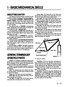
How the Handbook is organized. The chapters in this handbook are organized beginning at the pedals where the force is applied by the rider and continuing chapter by chapter to follow the force as it moves through the bicycle. This means that parts that work together are close to each other in the book. The pedals are attached to the crank, the crank is attached to the bottom bracket, and so on. Understaig that this is the order the chapters are in will also help you find your way around the book. A contents page is at the beginning of each chapter. This contents page gives an overview of what is in the chapter as well as directions to find related items that may be found in other chapters. The Appendix contains ISO standards, torque settings, conversion charts, as well as formulas, an index, and gearing charts.
Ball sizes .............................
2
Exotic materials ...............................
Bearing Mountings .......... 10 Drop-outs ........................... 10
Thread sizes ........................
2
Heat treating ..................................
Hubs ................................................ 11
Helpful information ...........
2
Work hardening .............................
Head tube ..................................... 11
Part identification .............
2
Annealing ........................................
Steerer tube .................................. 12
Thread Measuring ......
1
Cutting Operations ............
Fork crown .................................... 12
Example .............................
2
Tool steel ...................................... 6-7
Bottom bracket ............................ 13
Nationality of Parts
3
Lubrication and cooling ..............
Conclusion .................................... 13
Country ..............................
3
Sharpening ......................................
Illustrations .................................... 14
Standard used ...................
3
Drilling ..............................................
Standards ......................
3-4
About ..................................
3
Thread chasing ..............................
Hand Tools ............................ 15 About .............................................. 15 Wrenches ...................................... 15
National .............................
4
Milling and reaming ....................
Screwdrivers ................................. 15
De facto ..............................
4
Grinding ...........................................
Pliers ................................................ 15
ISO ......................................
4
Filing and sawing ...........................
Hammers ....................................... 15
Fits and Tolerances ............ 9 Bearings ................................ 9
Miscellaneous ............................... 15
Bearing design .................................
Suspension Tools ........................ 16
Symbols ..........................
2
Materials ............................... 5
Thread cutting ............................ 7-8
Cartridge or sealed .................... 1(
SUTHERLAND'S
Specialty bicycle tools ......... 15-16
HOW TO USE THIS BOOK SYMBOLS These symbols will he used to help you find the information you are looking for.
Ball Sizes Thread Sizes Things to watch for; helpful information
I D The easiest way to identify a part THREAD MEASURING
Example: 9/16" x 20 TPI The first number refers to the nominal diameter of the male part. When actually measured, as in Figure A, it is frequently slightl y undersize. The second number refers to the Number of Threads per inch (TPI) or the number of millimeters per thread as measured in Figure B with a thread pitch gauge. Threads must be clean when measuring. Any rocking motion back and forth indicates an incorrect match. In the past, the angle that threads were cut led to confusion. (See Thread Standards in the
Appendix.) In modern bicycles this is not a problem.
Correct
Incorrect
Figure B
SUTHERLAND'S
HOW TO USE THIS BOOK NATIONALITY OF PARTS Parts will he listed as English, French, Italian, Swiss, U.S., or Austrian to show the standard used in cutting the thread or the size of the parl. Manufacturers, however, do not always use their national standard and different sizes are used instead. For this reason, Raleigh and Schwinn will be given their own categories in the chart below. Country of origin does not necessarily indicate the national standard for a part. For instance, French bicycles that were exported to the U.S. on a large scale used English freewheel threads (BSC). COUNTRY
STANDARD USED
COUNTRY
STANDARD USED
Australia
English
Japan
English.
Austria
English, Austrian
Mexico
Italian
Belgium
English, some French
Netherlands
English
Canada
English
Norway
English
Denmark
Raleigh
English unless listed separately
Great Britain
English English1
Schwinn
English unless listed separately
Finland
English
Sweden
English
France 2
French (old) – English or ISO is current
Switzerland
French unless listed separately
Germany
English
Taiwan
English
India
English
United States
U.S., English
Italy
Italian
JIS,
U.S.3
1
Please note exceptions under Bottom Brackets and Headsets Chapters.
2
Used Swiss standard in bottom bracket briefly in late 1970's through early 1980's.
3 The Japan Industrial Standard(JlS ) is based on the English standard(BSC). Where JIS is different or no English standard exists we will point out the JIS standard. Japanese bikes imported to the United States are either U.S. standard or English standard. Generally, if it has an Ashtabula (one-piece) crank, it is U.S. standard; if it has a three-piece crank, it is English standard.
STANDARDS Confusion over thread sizes and interchangeability of parts used to be far worse than it is today. For example, matching bottom bracket threads on modern bicycles is not the problem it once was. However, when working on older hikes, it is important to know a little of the history of standards so problems can be avoided.
SUTHERLAND'S
HOW TO USE THIS BOOK STANDARDS (CONT'D)
National Standards In tact, there are standards. But there are so many of them. Back when American bicycles were sold in the U.S., French bicycles in France, Italian bicycles in Italy, and English bicycles most ever y where else . . . national standards worked most of the time. In the early 1970's, the demand for high-quality lightweight bicycles brought bicycles from all over the world to the U.S., and this is when the confusion began. Currently, there is the Japan Industrial Standard or JIS. Since many of today's Asian components conic from Japan or did until recently, they are made to JIS standard. Many of the JIS standards are based on the English standard so when there is no JIS standard listed in this hook, refer to the English standard.
De Facto Standards In addition to national and international standards, there are de facto standards. Sizes for man y BMX bikes, for example, are based on the Schwinn sizes because when BMX first began, Schwinn components were the most durable. The marketplace determined the standard. A similar situation used to exist for the high-quality road hike market. Because Campagnolo has been used by elite riders for years, a company making parts for this market has needed to make them interchangeable with "Campy." This led to a Campagnolo standard. A third de facto standard now exists in drive train components: the Shimano standard.
International Standards Manufacturers, distributors, and cyclists from various countries met in Geneva over a period of years and came up with standards for the International Standards Organization (ISO). The ISO is an international agency, a meeting ground for representatives of national standards organizations such as the U.S. American National Standards Institute. [he ISO attempts to standardize dimensions, markings, and safety requirements to increase compatibility, help international trade, and reduce product hazards. Standards are introduced slowly to avoid disruptions in trade. The ISO tries to make new, standardized equipment work as often as possible with existing equipment. For this reason, despite t he trend elsewhere towards metric standards, many of the ISO bicycle standards are based on English measurements. ISO thread form is slightly different From English, but parts are still compatible. Axle threads, wrench flats, and the like, which require the use of standard tools in manufacturing or servicing, are metric in the new ISO standards. Throughout this edition, we have included the ISO standards along with the various national standards. In addition, more detailed specifications are included in the Appendix. To stun up, standards exist; although they are never as comprehensive as we would like them to be, having different sets of standards is better than not having any standards at all.
SUTHERLAND'S
HOW TO USE THIS BOOK MATERIALS Working on bicycles requires some basic knowledge of metals and their characteristics. Contrary to the current use of the word in the bicycle trade, alloy does not mean aluminum, but rather indicates a mixture of metals. An alloy is generally a base metal such as steel or aluminum with relatively small percentages of alloying metals that impart desired characteristics to the base metal; these include strength, hardness, wear resistance, machinability, and corrosion resistance. The characteristics of a metal can be changed further by heat treating and/or work hardening.
Aluminum: Pure aluminum is a soft, weak metal with very good corrosion resistance. To be used for bicycle parts, it is alloyed with other metals to increase its strength and make it heat treatable. As this alloying degrades the corrosion resistance, most aluminum parts are anodized to protect against corrosion. Generally this coating is clear, although black and other colors are used. Steel: The most common steel used on bicycles is carbon steel, which ranges in carbon content from a few tenths of a percent in some frame tubes to about one percent in springs. Generally, the higher the carbon content, the stronger the steel. By adding small amounts of other metals such as chromium, molybdenum, or manganese, much stronger steel can he produced. These alloys are generally found in higher quality frame tubes.
Exotic Materials Most of the exotic materials bicycle frames are made with require very skilled labor, often in special environments. These frames need only minimal preparation at the shop.
Titanium: Pure titanium is a light, flexible metal. For bicycle use, it is alloyed with other metals, usually aluminum and vanadium, to increase its strength and durability. This alloying also increases the hardness of the metal, making it more difficult to work with. When working with titanium, you will need to have your tools sharpened often. Carbon Fiber: Carbon fiber is made from strands of monocrystalline carbon atoms. It is strongest in tension; carbon fiber strands can be strengthened in other directions depending on how the fibers are oriented. Carbon fibers need to be held together in a 'matrix', which is usually made from resin. Carbon fiber can be weakened by small cuts or holes, the same way a piece of tough plastic can be torn once a small notch has been cut into it. Leave cutting and drilling to the manufacturers.
Aermet 100: Though Aermet 100 is a type of steel, it is an especially hard metal. Do not attempt any cutting operations on it. However, Aermet 100 is mostly used for frame tubing
only and not for drop-outs, lugs, or the bottom bracket shell, so conventional cutting methods and tools can be used except on the tubing itself. Metal matrix composites are a class of materials and cannot easily be lumped together. Be careful though, most metal matrix composites have very hard materials added to them that can dull cutting tools quickly. .
Beryllium dust is extremely toxic. Therefore, beryllium should not be cut, milled, or tapped except in special environments not generally available to bicycle shops.
SUTHERLAND'S
HOW TO USE THIS BOOK MATERIALS (CONT'D) Heat Treating Most steel can be hardened by a variation of two general techniques: tempering and case hardening. Tempering: High carbon steel, and many steel and aluminum alloys may be tempered. In this process, the material is heated to a specific temperature and then quenched to harden it. The parts are held at another lower temperature for an appropriate length of time to lower the internal stresses and draw back the hardness to the desired point. This leaves the part uniformly hard throughout. Case Hardening: Case hardening can be used on low carbon steel, which generally cannot be tempered by the process of heat treating. Case hardening loads the surface of the part with a material, usually carbon, that will allow the surface to become quite hard while leaving the core unhardened. This is desirable to give a hard-wearing surface and a nonbrittle body. Case hardening also involves heating and quenching.
Work Hardening Another method of hardening, sometimes unintentional, is by work hardening. Bending, pounding, or manipulating the metal causes it to harden and become more brittle. This can be demonstrated by putting a sharp bend in a piece of wire and then attempting to straighten it. The bent part obviously has hardened and will not straighten to its original form. This characteristic makes it difficult to properly straighten a bent fork blade, because the bent section is now harder than the unbent section.
Annealing Annealing is the process of softening metal by heating it close to its melting point and slowly cooling. This also helps relieve internal stresses in the metal and allow alloying elements (or i mpurities) to redistribute over a slighter larger volume.
CUTTING OPERATIONS The tool used to work a material should be significantly harder than the material itself or the tool will wear quickly and not last very long. Because most tools found in bicycle shops were designed for use with steel frames, they may be inadequate for use with harder materials. (Please see Exotic Materials on page 0-5 for notes on titanium, carbon fiber, Aerrnet
100, metal matrix composites and beryllium.)
Tool Steel Cutting tools that are intended to cut steel are made of a special class of steel called tool steel. Tool steels may be either high carbon or alloy steel. Alloy steels are generally called high-speed steel, as they retain their edges at the temperature generated by high-speed cutting. Carbon steel tools are less expensive than high-speed steel and are generally quite adequate for thread cutting, reaming, and milling when the job is done by hand. The greater cost of high-speed steel is justified by increased durability when driven by a power tool. Drill bits for cutting steel should always
SUTHERLAND'S
HOW TO USE THIS BOOK CUTTING OPERATIONS (CONT'D ) be high-speed, as they will surely be used with a power drill. Regardless of the material used, all metal cutting tools have delicate, brittle cutting edges that are easily damaged by misuse. Many more cutting tools are broken than worn out. Do not throw them together in a box or a drawer.
Lubrication and Cooling When using cutting tools, both the tool and the piece to be cut must be properly lubricated and cooled with cutting oil. Most metal-cutting done on bicycles is in steel or aluminum. For best results in steel, use a high-sulfur base cutting oil available from hardware stores. It is also adequate for aluminum. Motor oil, bicycle oil, WD 40, or yesterday's coffee will not do in a pinch! You will dull your tools and do an inferior job unless you use the right cutting oil in the right quantity . Dabbing a little oil somewhere on the tool or work before cutting is a waste of time. The heat and friction are at the cutting edges. Keep them flooded with cutting oil throughout the operation.
Sharpening Even under the best conditions, cutting tools get dull. Mechanics throw razor blades away after a few shaves, but expect a tap to cut steel forever. It will, of course, but only if you get it resharpened before it gets so dull that it breaks off in a hole. Quality drills, taps, dies, milk, reamers, and the like can all be resharpened at a fraction of their replacement cost! When the tools don't seem to cut as cleanly and effortlessly as they did when new, look in the Yellow Pages under "Grinding—Precision and Production." Most large cities will have at least one shop that can do this type of work.
Drilling Probably the most common metal-cutting operation is drilling. Like other power-cutting operations, it requires eye protection and lubrication. The two lips on the end of the drill do all the cutting and should be kept flooded with cutting oil. The point between these lips is a small chisel that does not have a sharp edge and must be forced into the work. When drilling larger-diameter holes, you will find it much faster and easier to drill a pilot hole equal in size to the chisel edge on the larger drill. All drills, even when properly sharpened, make a hole larger than the drill bit by a small percentage. When improperly sharpened, this error may become quite large and the hole may not be round. Drilling with a dull bit causes overheating of the work, the bit, the motor, and the operator. The undue friction can cause the walls of the hole to become work hardened, which may lead to tap breakage if you attempt to thread the hole.
Thread Cutting 1.
It
is i mportant that the hole or shaft size be appropriate for the tap or die being used.
(For
tap drill sizes for common fasteners, see Appendix, page 17-6.) 2. If the tool is required to remove too much material, it will bind and possibly break. If too little material is removed, the thread will not be strong enough. In reality, the thread profile is never as sharp as the drawing on page 17-12. The strength of a thread is not improved significantly by exceeding 60% of the theoretical thread height pictured in the drawing.
SUTHERLAND'S
HOW TO USE THIS BOOK CUTTING OPERATIONS
(CONT'D)
3. Since all the cutting is done by the first few threads of the tap or die, these edges must be flooded with cutting oil during the threading operation. Failure to adequately lubricate these edges will result in rapid dulling of the tool, and torn and ragged threads in the work. 4. When threading, the tool should be reversed periodically to break the chip that is formed by the cutting edge. When threading a deep, small-diameter hole such as the rear axle adjuster in a drop-out, the tap should be backed out completely and chips removed from the tool to prevent binding and breaking. When cutting large-diameter fine-pitch threads such as bottom brackets and steerer tubes, the cutting tool must be accurately aligned wit h the work. A die stock with an accurate guide must be used on steerer tubes and a piloted double tap set must be used on bottom brackets to assure proper alignment of the bearing races and minimize tool wear or breakage. It is important to use the proper tap handle or die stock and
rotate evenly with both hands to prevent side thrust, which may result in broken tools and ruined work.
Thread Chasing Thread chasing is distinct from tapping in that it is not cutting threads, but is reforming damaged threads. Taps and dies designed for cutting threads may be used for this purpose as well as cheaper tools that are adequate only for chasing. While it may seem to be a much easier job, use care, and flood with cutting oil as in thread cutting. Most bottom bracket "thread chasers" have little or no pilot, making it difficult to align the tool with the hole. When chasing right-hand threaded bottom bracket threads with a pilotless tap, use a lockring threaded onto the tool to help judge straightness.
Milling (Facing) and Reaming The ends of the head tube and bottom bracket must be cut accurately so that they are parallel. Facing assures alignment of the bearing races and freedom from binding. The head tube must also be reamed so that the pressed bearing races will fit into the head tube properly. Facing and reaming operations are done with special cutters made for the job. As with other cutting operations, the tools must be sharp and well flooded with the proper cutting oil. Do not reverse the cutting direction when reaming or milling as this may cause the cutting edge to chip.
Generally, the face of the tube should be milled until the tool is cutting all the way around the hole.
Grinding Grinding may be used on any steel. It may be used on hardened steel, as normal cutting tools will not work. Grinding is a hazardous operation, requiring guards, eye protection, and proper technique. Grinding wheels must be sharpened and formed with a "wheel dresser" to get good results. Do not attempt to grind nonferrous metals such as aluminum or brass! Use a file or power sander for these soft metals or they will clog the pores of the grinding wheel.
SUTHERLAND'S
HOW TO USE THIS BOOK CUTTING OPERATIONS (CONTD)
Filing and Sawing These methods of metal cutting have a very important detail in common: they are generally done without lubrication. Always use top quality files and saw blades; their increased life makes them well worth the purchase price. Select the proper grade or teeth per inch for the material to be cut. Use fine teeth close together for steel or thin material, use larger teeth further apart for aluminum or thick material. At least two teeth should be in contact with the work at all times. Cut away from your body using a smooth slow stroke. Release pressure on the back stroke to protect the edges of the teeth. Files should be cleared of chips after a few strokes to prevent clogging, which affects speed of cutting and the quality of the job.
FITS AND TOLERANCES Parts that are meant to be assembled together must be designed to fit each other. The desired degree of tightness of the fit and the size of the parts determine the tolerance or amount of variation permitted on dimensions or surfaces of the parts. On threaded parts, the pitch of the threads and the length of the engagement must also be considered. Unfortunately, poor quality control in manufacturing can alter the results of even the best designs. Many of the "interchangeable" bicycle parts are so poorly made that to get a good fit, several "identical" parts must be tried. This shortcoming applies to some of the best known and most expensive components in the industry. Measuring a sample of bottom bracket components showed that several of the major Japanese manufacturers hold very good tolerances, but they are the exception. It is fortunate that bicycles are forgiving machines due to their simplicity, flexibility, and light loading. As bicycles become more important as vehicles for basic transportation or as manufacturers strive for better performance and less weight, let us hope quality control continues to improve.
BEARINGS
Bearing Design Bearings are used to minimize triction and heating where various parts rub against each other. The type of bearing used almost exclusively in bicycles is the ball bearing; it is very efficient, easy to fit, and inexpensive. Ball bearings fall into three general classifications which dictate their design and application:
radial bearings which are designed to be loaded at right angles to the axis of the shaft, thrust bearings which are designed to be loaded on the axis of the shaft, and a combined radial/thrust bearing which will accept some loading on both axes. The separate cup, cone, and ball arrangement used on most bicycles is of the
radial/thrust type. The major load on bicycle bearings is radial, except for the high thrust load on the headset lower bearing. Bicycle bearings are lightly loaded and rotate slowly. This allows the use of inexpensive, rather crude bearing surfaces. Except in very expensive components, these surfaces are stamped or machined rather than ground true to a fine finish. Grinding would add more to the cost than the minimal decrease in friction can justify.
SUTHERLAND'S
HOW TO USE THIS BOOK BEARINGS (CONT'D) Cartridge or sealed bearings are finding their way into quality bicycle components. These bearings, commonly used in industrial applications, have the balls captured between inner and outer races making up a one-piece unit. (ln a normal bicycle bearing, the cups and cones are the races.) These cartridge bearings are very precisely made and may include felt or plastic seals to hold in grease and keep out dirt and water, While this type of bearing is vastly superior, it lacks one important virtue that the cup/cone type bearing does have: it will not tolerate nearly as much misalignment as the cup/cone bearing can (and must). The thin flexible axle and the narrow spool of a standard bicycle hub cannot hold cartridge bearings in alignment. A larger diameter spool is required to keep the outer races aligned as the rider imposes both radial and thrust loads on the hub flanges. Similarly, the axle inside the hub must be larger in diameter to keep the Inner races precisely Lined up. Good design can accomplish this without a weight penalty.
BEARING MOUNTINGS Drop-outs — A bearing is no better than its mounting. The smoothness, efficiency, and longevity of bicycle bearings can usually be improved by refining the mountings found on the average bicycle frame. For general instructions on reaming, tapping, and milling (see previous section on cutting operations). Procedures for specific bearings follow.
Figure 2 Figure 1 Figure 1. Drop-out alignment gauges installed Figure 2. Drop-out out of alignment Figure 3. Drop-out aligned
Figure 3
SUTHERLAND'S
HOW TO USE THIS BOOK BEARING MOUNTINGS (CONT'D) Hubs The rear drop-outs and fork-ends arc an important part of the wheel bearing mounting. If the hub is clamped between non-parallel surfaces, the thin axle will bend and misalign the cones. Drop-out alignment gauges are made by Campagnolo, Park, and VAR to check and correct the alignment and spacing of drop-outs. (See Figures 1, 2, and 3.) These tools are a combination gauge and lever for bending the drop-outs into alignment. Use these tools to align only steel frames not aluminum or carbon fiber. (NOTE: Most mountain bike and road bike rear dropouts must be properly spaced and re-aligned for new 8-speed wheels.)
Head Tube The headset bearing cups seat in the ends of the head tube. The inside of the tube must be accurately reamed for a press fit and the ends of the tube must be milled parallel to align the cups. Bicycle Research Products, Campagnolo, Park Tool, VAR, and Zeus make tools which will do both of these operations; some head tools also serve as a press to install the cups. As shown (see Figure 4), the head tool has a T-shaped handle, a flat milling cutter, and a reamer mounted on a threaded rod. The rod is inserted in the head tube, and a centering cone, a spring, and a star nut are installed at the other end of the tube. The nut should be tightened to compress the spring about halfway. Flood the work area with cutting oil and rotate the tool clockwise, looking down on the handle. Do not reverse direction as this may cause the tool steel cutting edges to chip. As the tool turns, the reamer will go into the tube until the milling cutter contacts the tube face, (see Figure 5). More spring tension may be needed at this poinL Further rotation will cut the face of the tube at precisely 90° to its axis. Continue cutting until there is bright metal all the way around the tube. (It may be necessary to remove the tool to check this.) After one end of the tube is finished, repeat the procedure for the other end. After both ends are done, clean the metal chips and cutting oil from the tube. The tool may be used to press the cups into the head tube. A centering thrust washer is installed between the reamer and the bearing cup, as shown (see Figure 6). The centering cone and spring are not used in this operation. Make sure the cups start straight, then turn the handle until they are pressed tight against the tube ends,
(see Figure 7).
flat milling cutter ----- reamer centering cone spring -- star nut
Figure 4. Assembly for milling and reaming head tube Figure 5 Milling and reaming head tube
SUTHERLAND'S
HOW TO USE THIS BOOK BEARING MOUNTINGS (CONT'D)
reamer centering thrust washer bearing cups
star nut
Figure 6. Head cup press assembly
Figure 7. Installing head cups with press
Steerer Tube To assure that the threads on the top of the steerer tube are aligned with the tube axis, the die cutting them must be held in a die stock provided with a suitable guide, (see Figure 8). The top cone of the headset bearing depends on these threads for its alignment. Campagnolo, Hozan, VAR, and Zeus make the proper tools for this job.
Fork Crown Where the steerer tube enters the fork crown, the diameter of the tube and the top of the crown must be machined to accept the headset bottom cone. This job is best done on a lathe, but an acceptable job may be done with a crown race cutter as made by Campagnolo, VAR, or Zeus, as shown (see Figure 9). The tool is slipped over the steerer tube and the spring compressed to apply downward pressure to the hollow cutter. Using a cutting oil, rotate cutter clockwise until it leaves a complete circle of bright metal on the fork crown. Do not reverse direction as this may cause the cutting edges to chip. Clean the fork and drive the bearing cone in place with a hollow slide hammer or a piece of water pipe.
Figure 8. Steerer tube thread cutting
Figure 9. Fork crown race cutting
SUTHERLAND'S
HOW TO USE THIS BOOK BEARING MOUNTINGS (CONTD) Bottom Bracket The threads and the face of the bottom bracket shell are the mount for the crank bearing cups. Even if these are accurately machined, they will probably he distorted during the brazing of the frame. Bicycle Research Products, Campagnolo, Park, VAR, and Zeus all make a double tap with an aligning pilot shaft that may be used to correct or cut these threads. Select the proper taps tor the bottom bracket to be cut. The adjustable cup is always right-handed threading and the fixed cup varies right- or left-handed threading. To be sure if the fixed cup is right- or left-handed threading, (see Bottom Bracket Chapter page 3-2, Thread Sizes). Inspect the inside of the bottom bracket shell to make certain that none of the frame tubes extend into the path of the cutters. If they are in the way, they may damage the taps. Use a file for the slow and tedious job of removing the unwanted tube ends. Install the taps on the handles and insert the pilot shaft through the bottom bracket shell and into the hollow handle. (See Figure 10 on the following page.) Flood with cutting oil and start both taps into the shell at the same time, (see Figure 11). Run the taps in until there are enough complete threads to accept the bearing cups. Remove one tap and replace it with the flat facing mill and aluminum pilot, as shown (see Figure 12). Insert the handle onto the protruding pilot shaft until the cutter is against the shell. Using cutting oil, press in and turn clockwise (do not reverse) until the bright metal shows all the way around the end of the shell, (see Figure 13). Repeat on the other end of the shell, changing taps if required. Clean up chips and oil, including the chips hiding in the chain stays, and install the bottom bracket. Since Italian threading is the largest diameter, a bottom bracket shell with stripped or badly damaged threads may be made as good as new by converting to Italian standard threading, unless it was already Italian thread. Remove the old threads using a Bicycle Research Product Bottom Bracket reamer on one side of the double tap handle, with a tap matching the threading in the shell threaded into the other side, as shown (see Figure 14). Using cutting oil, push the reamer into the shell while turning it clockwise until the old threads are removed. Continue turning clockwise while pulling the reamer out of the shell. Without removing the tap, replace the reamer with an Italian tap and cut new threads. Leave the Italian tap in the shell and remove t he other tap. Replace this tap with t he reamer and repeat the reaming and threading operations. This fast, easy repair saves a ruined frame for the cost of the bearing cups and twenty minutes work. The old spindle may be used, if serviceable.
I N CONCLUSION Always keep in mind that a bearing may only function if it is rigidly and accurately mounted. The more precise the bearing, the more vulnerable it is to misalignment.
SUTHERLAND'S
HOW TO USE THIS BOOK BEARING MOUNTINGS (CONT'D )
Figure 10. Installing double-sided tap with aligning shaft
Figure 11. Starting taps
aluminum pilot facing mill
Figure 12. Milling assembly
Figure 13. Milling bottom bracket face
Figure 14. Reaming bottom bracket shell to remove stripped threads
SUTHERLAND'S
HOW TO USE THIS BOOK HAND TOOLS Screwdrivers, pliers, wrenches, hammers, and various special tools are used in bicycle repair and assembly. The quantity, quality, and profitability of work done in a shop generally matches what is found on the work bench. A good tool is a long term investment, but a poor or missing tool continues to run up expensive labor costs. Screw heads marred by a dull screwdriver, or nuts rounded by an adjustable wrench tell a customer where not to take his or her bike next time. For a shop doing repair work on all makes of bicycles, many tools are needed. Consider the tools in the following list as a basic minimum for a profitable shop. WRENCHES
MISCELLANEOUS (CONT'D)
6mm through 17mm Combination 6mm through 17mm Box End 1/4" through 5/8" Combination 13mm through 17mm Cone Wrenches Pedal Wrench 6", 8", 12", and 16" Adjustable Wrenches 8mm through 15mm Socket Wrenches Metric Allen Set (1.5mm - 10mm) Inch-size Allen Set Torque Wrench
18" Straightedge Hacksaw Files Thread-pitch Gauge, Metric and English 6" Bench Grinder Grinding Wheel Dresser Wire Wheel 3/8" Drill and Bits
SCREWDRIVERS
1/8" or 3/16" Wide Blade Type 1 /4" or 5/16" Wide Blade Type Various sizes Phillips-type PLIERS
8" Slip Joint 7" Diagonal Cutter 6" Long Nose 12" Channel Lock Cable Cutter SIS Cable Casing Cutter HAMMERS
1/2 lb. Ball-peen 1 lb. Rubber Mallet MISCELLANEOUS
Center Punch Set Pin Punches 5" Bench Vise, 50 lbs. or more in weight 6" (15cm) Calipers 6" (15cm) Machinist Scale 6' (2 Meter) Tape 2.5 Meter Flat Metric Tape
SUTHERLAND'S
SPECIAL BICYCLE TOOLS
Every type Freewheel and lockring Tool you can find Every type Crank Extractor you can find Shimano Ball Cup Tool Spoke Wrenches 1/2" and 9/16" left and right Pedal Taps 5, 6, and 10mm Taps Bottom Bracket Fixed Cup Remover Bottom Bracket Lockring Tool Bottom Bracket Peg Spanner Cotter-pin Press Cup Press Third-hand Brake Tool Fourth-hand Brake Tool Chain ring Tool Axle Thread Chasers Various Special Shimano Tools Chain Rivet Extractor Drop-out Alignment Tool Shimano Derailleur Hanger Tool Alignment Tool Wheel Dishing Tool Repair Stand Truing Stand Phil Spoke Cutter Threader
HOW TO USE THIS BOOK HAND TOOLS (CONT'D) SPECIAL BICYCLE TOOLS-SUSPENSION FORKS
Specialty tools are supplied by the manufacturer in consumer tool kits and the tool designs change annually. Hopefully, the bicycle industry will not need many specialty tools for suspension forks in the future, as many manufacturers streamline repairs to use basic tools such as seal pullers, snap ring pliers, air pumps, and hands. 1" stanchion vise blocks Seal separator (puller) Snap ring pliers Long 4mm alien Long 5mm al len Long 6mm alien
Long 8mm alien Phillips screwdriver Fork air pump w/needle 19mm socket 22mm socket
Metric ruler Rebuild kits Teflon-based grease Blue Loctite Flat blade screwdriver
ONE LAST WORD ABOUT TOOLS: — Cheap tools are an extravagance no bicycle shop can afford.—
SUTHERLAND'S
CONTENTS
1
Pedals
Cleats
Shoes
Ball and retainer sizes ................... 2
Fixed ................................................ 3
Compatibility and drilling ......... 4
Thread sizes ..................................... 2
Floating ........................................... 3
Adapters .......................................... 4
Markings on wrench flats ........... 2
Parts of clipless system .............. 3
Bolt patterns .................................. 4
Markings on crank arms .............. 2
Compatibility and drilling ......... 4
MTB conversion chart ............... 4
Right & left-handed threads ..... 2
Bolt pattern .................................... 4
Drilling .................................. 4
Toe clip bolt - pedal ...................... 2
Clipless cleats chart ................. 5-7
Adapters ................................ 4
Compatibility and drilling .......... 4
Cleat adapters .................. 5-7
Road conversion chart ............... 4
Clipless pedals chart ................. 5-7
Drilling .................................. 4
Bolt pattern .......................... 5-7
Adapters ................................ 4
Release adjustments ............ 5-7
Shoe size conversion chart ........ 7 Universal adapters ....................... 7
SUTHERLAND'S
PEDALS, CLEATS, SHOES PEDAL-CRANK Ball and Retainer Sizes Sealed cart. bearings SunTour inner pedal SunTour outer pedal Onza '94 Time
Most pedals use 10 to 15 5/32" per side or 1/8" balls
Bearing no.
6500 698 686 6901
ID 10mm
5mm 6mm 12mm
OD 19mm 20111m
12mm 24mm
Thread Sizes 150* Primary Alternate English French** Italian U.S.A.
1/2" x 20 TPI 9/16" x 20 TPI 9/16" x 20 TPI 14mm x 1.25mm 9/16" x 20 TPI 1/2" x 20 TPI
Right- and left-handed thread Right- and left-handed thread Right- and left-handed t hread Right- and left-handed thread Right- and left-handed thread Right- and left-handed thread
Italian threads are slightly different than English and are a tighter fit in English t hreaded cranks. * See .appendix for more details on ISO standards. ** Peugeots and some other french bicycles have used English 9/16" x 20 TPI for the U.S. market since the mid '70s. French cranks can easily be tapped to 9/16" x 20 TPI.
When retapping pedal threads, start from the hack of the crank arm.
ID
Markings on Wrench Flats Campagnolo, others Zeus
English, Italian French
ID
BSC no mark
Markings on Crank Arms English French Italian
ID
9/16" x 20 14 x 1.25
European
Japanese
9/16" x 20 14 x 1.25 9/16" x 20
no mark M14
Pedal Codes for Right- and Left-handed Threads English French Italian Spanish
Right
Left
R I7
L CT
Toe Clip Bolt — Pedal Use 5mm x 0.8mm threads.
SUTHERLAND'S
PEDALS, CLEATS, SHOES CLIPLESS PEDALS ,CLEATS, AND SHOES
Types of Clipless Systems Fixed Cleat The fixed cleat system keeps the shoe stationary in the pedal. The shoe may be able to twist or slide from side to side, but there will be a returning or centering force trying to return the shoe to its original position. It the shoe is moved against this centering force beyond a certain position, the cleat and pedal will disengage. Some older systems needed to be disengaged by hand.
Floating Cleat The floating cleat system allows the shoe to float, or rotate from side to side, in the pedal. The shoe is able to twist or slide from side to side within a given range, with little or no return force. Outside this range either the pedal and cleat immediately disengage, or the return force progressively increases until the cleat disengages.
Parts of the Clipless System Cleat - The piece on the shoe that attaches to the pedal; it allows the shoe to latch and unlatch from the pedal. Cleat adjustment describes adjusting the cleat to the rider's foot over the pedal. Clipless systems have fore and aft adjustment. In addition, most have side to side and rotational adjustments. Pedals - Generally, the clipless systems come with 9/16" threaded axle spindles, two sided pedals with mounting brackets, or plates for mountain bikes, or single sided pedals for road. The pedal controls the tension capabilities. Release Tension Spring - This spring, adjustable on most pedal systems, controls the tension which releases the cleat from the pedal. The rider must twist the shoe to one side which releases the shoe from the pedal. Adapter plates - These plates allow adaptability from shoe to pedal. The three main types are: shoe adapter plates that are made to fit one specific manufacturer's shoes (usually within the recess in the shoe); cleat adapters that are made to adapt the drilling of one specific manufacturer's cleat to a different drilling on a shoe; and universal adapter are plates that adapt one style of drilling to a different bolt pattern.
SUTHERLAND'S
shoe
PEDALS, CLEATS, SHOES COMPATIBILITY AND DRILLING Shoes and clipless pedals are matched to each other by matching shoe drilling with cleat bolt patterns. Each cleat has one bolt pattern, but cleat adapters can be used to match the cleat to a different shoe drilling. Shoes can have multiple drilling to match different cleat bolt patterns. Some shoes have shoe adapter plates to match various cleat bolt patterns. Most cleats have one of the three primary bolt patterns: 2 hole/SPD, 3 hole/Look, or 4 hole/Time. Other cleats have a unique bolt pattern that matches a shoe made specifically for them. Often these cleats will come with a cleat adapter plate to match one of the primary shoe drilling. Bolt patterns 2 Hole/SPD 3 Hole/Look 4 Hole/Time
Spacing 12mm apart 31.5 x 31.5 x 33mm 16.5mm wide x 54mm long
There are also shoes with custom drilling unique to the shoe design. These often have recesses for the shoe adapter plates and the shoe adapter plates may have any one of the three primary drilling in them. Example for using the charts: Vittoria shoe to an Onza pedal, look under "Clipless Pedals and Cleats" on page 1-5, the Onza H.O. cleat has a 2 hole/SPD drilling. Then look below for the Shoes - MTB, find the Vittoria shoe; it has a 2 hole bolt pattern. The Vittoria shoes will work with the Onza pedals and cleats with no adapters needed.
Shoes — MTB Shoe Drilling
Make ALPINESTARS CARNAC
2 Hole/SPD 3 Hole/Look Custom
Shoes — Road Shoe Adapter Plates for Bolt Patterns
2 Bolt/SPD, Speedplay, Toe Clips
DIADORA
2 Hole/SPD, Custom DUEGI 2 HOLE/SPD GAERNE 2 Hole/SPD LAMSON 2 Hole/SPD LAKE 2 Hole/SPD NIKE 2 Hole/SPD PERFORMANCE 2 Hole/SPD SCOTT 2 Hole/SPD SHIMANO 2 Hole/SPD SIDI Custom SPECIALIZED TIME VITTORIA
2 Hole/SPD 4 Hole/Time 2 Hole/SPD 3 Hole/Look
3 Bolt/Look, Toe Clips 1
Make
Shoe Drilling
Shoe Adapter Plates for Bolt Patterns
CARNAC
Custom
Ergo, Speedplay, 2 Bolt/SPD, 3 Bolt/Look, 4 Bolt/Time
DETTO PIETRO DIADORA
3 Hole/Look 3 Hole/Look Custom/Ergo 2 Bolt/Time, 4 Bolt/Time 3 Hole/Look 2 Hole/SPD, none 3 Hole/Look 2 Hole/SPD 3 Hole/Look and Custom 2 Hole/SPD, 3 Hole/Look 3 Hole/Look 2 Bolt/SPD, 4 Bolt/Time and Custom 3 Hole/Look 4 Hole/Time 3 Bolt/Look, Speedplay 3 Hole/Look Ergo, 2 Bolt/SPD, and Custom 4 Bolt/Time
EURO LAKE NIKE
3 Bolt/Look recessed - none 2 Bolt/SPD, 3 Bolt/Look, Toe Clips recessed - none 2 Bolt/SPD, Speedplay 3 Bolt/Look 2 Bolt/SPD
SHIMANO SIDI SPECIALIZED TIME VITTORIA
1 Lamson makes soles to order for 3 Bolt/Look, Speedplay, and Diadora.
SUTHERLAND'S
PEDALS, CLEATS, SHOES Clipless Pedals and Cleats — MTB Make BEBOP GRAFTON
LOOK
Pedal Model
Cleat
Bolt Pattern
Cleat Adapters
Float
Release Tension
MTB all1
Bebop
2 Bolt/SPD
15°
none
Grafton
3 Bolt/Look
10°
allen
S2R and 525 MP-90 8
MicroLook Black, Red
2 Bolt/SPD Custom
6° fixed,6°
flathead
MKS
2 Bolt/SPD
fixed
alien
6°, 10°
replace elastomer
MKS
ONZA
H.O.
Onza
2 Bolt/SPD
RITCHEY
Logic, Logic WCS
Logic
2 Bolt/SPD
SHIMANO
M525 M737 M323 1,7
SM-SH5O
allen fixed fixed 5 6° 6°
allen
SM-SH71
2 Bolt/SPD 2 Bolt/SPD 2 Bolt/SPD 2 Bolt/SPD
M535 M747
SM-SH50 SM-SH55 SM-SH51 6 SM-SH70 SM-SH71
2 Bolt/SPD 2 Bolt/SPD 2 Bolt/SPD 2 Bolt/SPD 2 Bolt/SPD
2° 2°5 12° fixed 12°
allen
SPEEDPLAY
Magnum Frog
SpeedPlay Frog
2 Bolt/SPD 2 Bolt/SPD
56° 2502
none none
TIME
MTB
TMT
Custom4
10° 3
none
TIOGA
Clipman
Clipman
2 Bolt/SPD
3°
alien
VICTOR
VP-101
VP
2 Bolt/SPD
SM-SH55 SM-SH51
2 Hole/SPD
alien
1
Standard toe clips can be used on some models.
2
25° of heel outward float, 0° inward, cleat can be rotated to adjust the inward and outward float.
3
Cleat also has 10mm of side to side play.
4
TMT uses standard 2 Hole/SPD drilling, but the cleat is thicker than standard 2 Hole/SPD cleats.
5
Shimano SM-SH55 allows easier release than SM-SH50 .
6
This is the recommended cleat for this pedal.
7
Shimano tool TL-PD32 is needed to remove the plug on the pedal before a cleat can be used.
8
Look MTB is a custom 2 Bolt pattern.
SUTHERLAND'S
PEDALS, CLEATS, SHOES Clipless Pedals and Cleats — Road Bolt Pattern
Cleat Adapters
Float
Release Tension
California Lite
custom
3 Hole/Look
none
none
SGR
SGR
3 Hole/Look
—
0 - 10°
allen
CINELLI
Uniblock
Uniblock
custom
— —
fixed
manual release
DIADORA
Ergo
Static Dynamic
custom
3 Hole/Look 3 Hole/Look
fixed 8° 2
allen none
custom
3 Hole/Look
fixed
none
Make
Pedal Model
AEROLITE
Turcite
CAMPAGNOLO 1
Cleat
KEYWIN LOOK
MAVIC MKS
PP286 or
Black "FAC"
Red "FREE ARC"
3 Hole/Look 3 Hole/Look
—
PP276
—
fixed 0", 3° 6°, 9°
flathead flathead
PP96 1990
Red ARC '90, 3 Hole/Look 3 Hole/Look Grey 1990
— —
6° fixed
flathead flathead
standard road 3 Red "FREE ARC" (and or "ARC" '91 compatibles) Black "FAC" or "F"
3 Hole/Look
—
9°
flathead or alien
3 Hole/Look
—
fixed
flathead or alien
645LMS
Black Look, "FAC" or "F"
3 Hole/Look
—
fixed
flathead
MXP-115
2 Hole/SPD
—
fixed
alien
3 Hole/Look
—
20°
screw
3 Hole/Look
—
902 902 (earlier model)
3 Hole/Look
—
fixed 0-15° 4 4°
spring replace alien
Ultegra 6402
SM-SH24
3 Hole/Look
—
fixed, 9°
Dura Ace or Ultegra SPD
SM-SH70 SM-SH71 SM-SH50
2 Hole/SPD 2 Hole/SPD 2 Hole/SPD 2 Hole/SPD
3 Hole/Look 3 Hole/Look — —
fixed
2 Hole/SPD
—
3°
MXP-110 Mapstage
SAMPSON
SHIMANO 1
Stratics
Stratics
SM-SH51 SM - SH55
0-10°4
12° 3° 3°
alien alien alien alien allen
A525(see MTB pedal
M525)
SUTHERLAND'S
PEDALS, CLEATS, SHOES Road (cont'd)
Clipless Pedals and Cleats
Bolt Pattern
Cleat Adapters
Release Tension
Make
Pedal Model
Cleat
SPEEDPLAY
X/1 or X/2
X-series
3 Hole/Look, Carnac, 4 Hole/Time Nike, Sidi, and Time Shoes6
+29° -8°5
none
SR
FXP-100 (See Sampson 902)
FXP-100
3 Hole/Look
—
4°
alien
TIME
TBT TWT
TBT
4 Hole/Time
3 Hole/Look
10° 7
none
TWT
custom
10°7
none
Float
1
Also makes Look compatible pedals. See Look standard road.
2
Allows 6mm of side to side play.
3
Low end models do not have release tension adjustment.
4
Play is independently adjustable inward and outward.
5
Has 29° of heel outward float and 8° of heel inward float (37° total).
6
Proper length screws are available for Carnac, Sidi, and Time shoes.
7
Depending on the pedal model, the cleat has 10 to 14mm of side to side play.
Shoe Size Conversion Chart 8
8.5
40.5
7.5 41
42
415
12 47
12.5 47.5
13 48
U.S. European
4 36.5
4.5 37
5 38
5.5
6
6.5
7
38.5
39.5
40
U.S. European
9 43
9.5 43.5
10 44 44.5
10.5 45
11 45.5
11.5
46
CARNAC + ONE SIZE UP
Universal Adapters Make
Shoe drilling
Cleat style
Syntace
3 Hole/Look (Look) to
2 Hole/SPD
Thompson
none - chip**
3 Hole/Look (with Look cleat)
Winwood
none - clip**
2 Hole/SPD (with SPD cleat) 3 Hole/Look (with Look cleat) 4 Hole/Time (with Time cleat)
** Allows clipless pedals to be used like standard toe clips with street shoes.
SUTHERLAND'S
PEDALS, CLEATS, SHOES
SUTHERLAND'S
CONTENTS
Cranks
Chainrings
Chain
Cotterless crank spindles
Bolts/spacers chart ................... 8
Characteristics
Bolts and nuts ......................... 2
Rings ..................................... 8
Size ....................................... 20
Thread sizes ............................ 2
Spacing ................................. 9
Number of links ................... 20
Cotterless crank extractors ... .... 2
Thickness ............................... 9
Bushings ............................... 21
Installing cotterless cranks ......... 4
5-arm chainrings and crankarms
Chain dimensions ................ 21
interchangeability ....... 10-16
Width/Pin length ................. 21
and spindles ........................ 4-5
About adapters .................. 16
Chain cutting notes ................. 22
Taper angles ........................ 4-5
Adapter interchangeability .. 17
Fit between cotterless cranks
Taper end sizes ........................ 5 Taper length notes .................. 6 Crank arm profiles ...................... 7 Crank cotters ............................ 23
5-pin chainrings interchangeability ............ 1 8 6-bolt chainrings interchangeability ............ 1 8 3-arm chainrings interchangeability ............ 19
SUTHERLAND'S
CRANKS, CHAINRINGS, CHAIN COTTERLESS CRANK SPINDLE BOLTS AND NUTS
Thread Sizes Most Including 150 Bolt-type Nut-type
8mm x 1.0mm 1 0mm x 1.25mm
Exceptions Viscount may be 5/16" x 26 TPI or 22 TPI Campagnolo Super Record is 10mm x 1mm
COTTERLESS CRANK EXTRACTORS Most extractors have the same external threads (22mm x 1mm). The exceptions are on the next page in bold in the size column. Even with extractors that have the same nominal thread size, manufacturing variations in the extractor and/or the crank do occur. Keep several tools around; if one tool goes on too tightly or too loosely, try another that matches the threads more closely. Nut-type crank extractors must be used on nut-type spindles. The center bolt on bolt-type extractors cannot be pulled back enough to engage the threads in a crank mounted Oil a nut-t y pe bottom bracket spindle. Campagnolo 1990-Record, (C-)Record, Croce d'Aune and Victory crank arms have left-handed extractor threads. Use only the built-in extractor (see drawing below) or Campagnolo's special left-threaded extractor. Do not use the Park crank extractor on pre-1952 Stronglight cranks: the threads may strip. The Park tool will work where a bolt-type, nut-type, or TA extractor is used. A Bicycle Research Products crank arm thread-chaser (TC-8) will restore cross-threaded or slightly damaged crank threads. It will not work on completely stripped threads. If the threads are completely stripped, use a gear-puller to pull the crank. To remove frozen crank dust caps, drill two small holes in them and use a pin tool. Grease the threads before installing dust caps.
crankbolt with built-in
left-threaded extractor.
SUTHERLAND'S
CRANKS, CHAINRINGS, CHAIN COTTERLESS CRANK EXTRACTORS (CONT'D ) Bold numbers indicate exceptions to common 22mm x 1mm Make/Standard
Type Spindle .'
150 2
Thread
Crank Bolt
or Nut size
Extractor
Size
bolt-type nut-type
14mm 14mm
bolt-type nut-type
22mm x 1 mm 22mm x 1mm
bolt-type
6mm allen
built into dust cap or use Campagnolo's special leftthreaded extractor
22mm x 1mm left - threaded
Super Record all others JIS
nut-type bolt-type
14mm 15mm
nut-type bolt-type
22mm x 1mm 22mm x 1 mm
bolt-type nut-type
14mm 14mm
bolt-type nut-type
22mm x 1mm 22mm x 1mm
Lambert (early)
bolt-type
SR (Sakae Ringyo)
bolt-type nut-type
14mm 14mm
bolt-type nut-type
22mm x 1 mm 22mm x 1mm
Shimano 5
bolt-type
14mm
bolt-type/8mm allen
22mm x 1 mm
Specialized
bolt-type
15mm
bolt-type
22mm x 1mm
Stronglight3 pre-1982
bolt-type
16mm
Stronglight—pre-1982, Var 22
23.35mm x 1mm
bolt-type
14mm
bolt-type
22mm x 1 mm
Sugino
nut-type bolt-type
14mm 15mm
nut-type bolt-type
22mm x 1mm 22mm x 1 mm
TA
bolt-type
15mm
TA, Var 392, Var 393, Var 408
23mm x 1mm
Takagi
nut-type
14mm
nut-type
22mm x 1mm
Viscount
bolt-type
15mm
bolt-type
22mm x 1 mm
Zeus
bolt-type
16mm4
bolt-type
22mm x 1 mm
Campagnolo 1990 Record, Croce d'Aune, (C-) Record, Victory
1982-current
7/8" x 24 TPI
1
(See page 2-2) for drawings of spindle types.
2
See Appendix for more details on ISO spindle standards.
3 Extractors: Pre-1982 Stronglight extractors have a shoulder at the end of the threads. Do not use a TA tool (or the TA threads of a Park tool). These tools will screw into an older model Stronglight crank but will probably strip the crank threads when you attempt to pull it. Bolts: For 16mm bolts, use a thin-walled socket with an outside diameter no larger than 22mm. Do not use the older 16mm bolts with newer cranks that have 22mm extractor holes. Only a very thin-walled socket or Zeus extractor will remove them.
4
Use a Zeus tool or a very thin-walled socket with an outside diameter no larger than 20.8mm. If you ever get the bolt out, use a 15mm bolt instead.
5 Shimano Dura-Ace AX, Dura-Ace EX, 600 AX, 600 EX, and Deore used a built-in extractor that didn't work very well. It is probably best to replace them with a conventional dust cap and crank arm bolt.
SUTHERLAND'S
CRANKS, CHAINRINGS, CHAIN I NSTALLING COTTERLESS CRANKS Adjust the chainline by selecting the appropriate parts-usually the correct length spindle. (See Buttons Bracket Spindles, page 3-8.) The cranks mount in one position. Do not overtighten or leave loose to adjust the position. Adjust the bottom bracket bearings with the cranks off. Install the right crank. Check bearing adjustment by putting side force on the end of the crank. Readjust until no play is felt. Install left arm. The spindle end and the hole in the crank must be clean and dry. Do not use oil, grease, or an anti-seize compound. The tapered square system depends on the crank coming up firmly on the spindle. Any lubrication will cause the arm to go on too far in tightening or to float on the spindle. Either way, the arm will be mined. Grease or anti-seize compound may be used on the threads of the crank bolt. Tighten the crank bolt firmly: 18-20 foot pounds (215-240 inch pounds). Re-torque the bolt after 100 miles of riding. This ensures that the crank seats properly on the spindle.
spindle
Figure A: Incorrect fit
Figure B: Correct fit
Figure C: Incorrect fit
Crank close to "bottoming" on end of taper flats.
Spindle end is not flush with bottom of crank extractor hole and crank arm does not "bottom" on end of taper flats.
Spindle end flush, or close to flush, with bottom of extractor hole.
FIT BETWEEN COTTERLESS CRANKS & SPINDLES Spindle end and crank hole dimensions vary considerably due to manufacturing tolerances.
Taper Angles JIS spindles are 2°. A very rare, out of production SR Silver crankset used a 3" taper. 3' taper ends are too wide to fit in a crank made for 2° spindles. When crank and spindle taper angles differ, the spindle will wobble when loosely inserted into the crank as a test. Except when angle errors are extreme, the crank will seat itself during initial use, requiring only a few re-tightenings of the crank bolt.
SUTHERLAND'S
CRANKS, CHAINRINGS, CHAIN FIT BETWEEN COTTERLESS CRANKS fit SPINDLES (CONT'D) Taper Angles (CONT'D) Failure to re-tighten the crank bolt will eventually destroy the crank. Most of the difficult crank-fit problems are due to taper length differences, not angle differences.
When using the interchangeability charts, tighten the crank on the spindle to check the fit before installing it on the bike. Be sure the crank does not come up against the end of the taper. This happens first near corners of holes. if the crank bottoms out, the square holes do not grip well, and will come loose or possibly crack. (See figure A on page 2-4.) After tightening, remove bolt to check that the end of the spindle is not coming through. If the spindle end is flush or near flush with the face of the crank bolt washer it sits against, (see figure C on page 24), the crank itself may not be tight enough or will loosen when ridden. Attempting to tighten the crank bolt further with this condition present will shear off the bolt, since it would be tightening against the spindle end itself. Sometimes you can use a washer between arm and normal washer. File a hole in an unhardened washer so the spindle end corners can pass through it.
Taper End Sizes While the angle of the taper end is nearly always close to 2', the size of the end does vary. Older Ofmega and Zeus spindles had the smallest taper end. This meant that these spindles would go in other brand cranks so far that the end of the spindle would be flush with the bottom of the crank hole. This would prevent the crank bolt from tightening enough to hold the crank firmly in place. This is a list of spindle end size tendencies from smallest to largest. Individual spindles may he smaller or larger depending on the batch they were made in. Ofmega Zeus ISO JIS Campy
We would like to be able to provide exact numbers for the spindle ends but the ISO is the only one that has published dimensions and tolerances (see Appendix). The JIS standard for spindle ends is 12.65mm but no manufacturing tolerances are given. Measuring actual spindles only confuses things since they vary so much. Except for Ofmega and Zeus spindle ends are very close in size and can be interchanged if care is taken. Be sure when interchanging that the taper length is not going to cause a problem.
SUTHERLAND'S
CRANKS, CHAINRINGS, CHAIN FIT BETWEEN COTTERLESS CRANKS Sr SPINDLES (CONT'D) Taper Length Notes XTR cranks have deep holes that prevent mounting a spindle that has shorter taper flats. You must use a spindle designed for XTR cranks.
Old combinations that don't work • TA cranks: crank bolt face comes close to flush with the ends of many spindles. • Stronglight, JIS (Japan Industry Standards), and Sugino AT cranks: bottom on the
ends of the flat on most spindles except Stronglight, I A, JIS and Phil Wood. • JIS nut-type spindles: stud does not protrude far enough through extractor
hole of many cranks to engage nut. • Ofmega and older (indented markings) Avocet spindles and cranks: spindle end and crank hole are narrower than others; do not interchange. Zeus also is narrower,
though less so; take care that the spindle does not come flush with extractor hole when installing another brand of crank on a Zeus spindle.
Old useful combinations that do work • JIS spindles can be used to place chainline farther from the frame with Stronglight or TA cranks. You may also grind the end of a bolt-end spindle. Bevel the edges so it doesn't dig into the crank when tightened. Try the bolt before assembly. You may have to shorten it slightly.
Miscellaneous Items If you are using light alloy crank bolts, do not use them to install the cranks. Use normal steel bolts to tighten and retighten the arms. Then remove the steel bolts and install the alloy bolts. Tighten them finger-tight, then just enough more to tension them. Always replace the dustcaps. They prevent damage to the threads. Damaged threads may make it difficult or impossible to install an extractor. A small amount of grease on dust cap threads will prevent corrosion.
SUTHERLAND'S
CRANKS, CHAINRINGS, CHAIN CRANK ARM PROFILES Comparison of High Profile, Low Profile, and Super Low Profile Crank Arms
A
High profile
B
C
Low profile
D
E
Super Low profile
The crank arm in figure A is an old style crank arm. The arm in figure C is a low profile arm (pre '94) and the arm in figure E is the newer super low profile arm. Looking quickly at these arms, it would seem that if you wanted to keep the chainline in the same position and replace the high profile arm with either the low profile or super low profile arm, a much shorter bottom bracket spindle would be needed. Figure B and D show the two arms superimposed with chainring position showing as the same for both. The difference, in figure B, turns out to be only 3mm (see the red area where the crank bolt washer would be). In figure D the difference is 8mm and in figure F is 11mm. This difference varies, of course, with various models. The point is that the bottom bracket spindle length can vary greatly and careful measuring of chai n I ine is imperative.
SUTHERLAND'S
F
Crank Arm lengths
165mm 167.5 170 172.5 175 177 177.5 180 181 185 195
CRANKS, CHAINRINGS, CHAIN CHAINRING BOLTS/SPACERS Hex-headed bolts should be tightened and loosened with a socket or box-end wrench that has a face that has been ground flat.
Thread
Bolt Length (approx.))
Nut Length (approx.))
Hole in Arm, Chainring or Spacer ID
Notes
Double
8mm x .75mm
8 - 9mm
7mm
10mm
Use 5mm alien key,
Single
8mm x .75mm
7mm
3.5 - 4mm
10mm
Triple inner
8mm x .75mm
8 - 12mm
8mm
Special inner triple
6mm x 1mm
16mm
6mm
Chainring Bolt and Nuts Type A
slotted nuL Hold nut with special tool.
Triple (see Type AA) Type AA (inner) Use 5mm alien key
6mm x .75mm Type B
6mm x 1mm
8mm
Use slotted nut
Type C
7mm x 1 mm
threaded
Collar diameter 8.9mm
7mm x 1mm or unthreaded 7mm 7mmx l mm
Type D (TA)
7mmx l mm threaded
5mm x .80mm
Type E
Type A/Double
Type AA/Inner
7mm or 8mm
Use slotted nut or
or 5mm x .75mm
4mm alien key
Type B and E
Type C
Type D (TA)
optional lOmm
Rings Middle and outer chainrings on triples have 10mm holes with 12mm recess .5 - 1 mm deep. Inner triple chain rings have 8mm bolts. Generally, steel and titanium inner chainrings have no recess (this also sometimes allows the user to simply flip the chainring over for increased chainring life, depending on the bevel of the teeth).
SUTHERLAND'S
CRANKS, CHAINRINGS, CHAIN CHAINRING BOLTS/SPACERS (CONT'D) Spacing 4.5mm is a good working space between the closest chainring surfaces for use with narrow chain. Chainring spacing must be narrow enough that the chain does not fall between the chainrings. Spacing must also be wide enough that the chain does not rub the next larger chainwheel in any useful chainring - freewheel sprocket combinations. Chainrings vary in thickness as does the depth of the recess in the hole. When replacing chainrings, these variations need to be accommodated with spacers of different thicknesses. Replacing aluminum chainrings with steel or titanium chainrings often requires adding very thin spacers.
Chainring Spacers
Thlckness
Outside Dlameter
Inside Diameter
Type A
.6 - 2mm
14mm
1 0mm
Not used on some cranksets.
4mm
14mm
10mm
Flattened on one side for chain clearance when using 38T chainring.
2 - 7mm
12mm
8mm
Not used on some cranksets.
.15mm
12mm
8mm
Crank arm for SG chainrings.
HD-C 9mm
12.5mm
7.9mm
To adapt crank arm for SG chainrings.
Double Triple (See Type AA) Type A
Mavic Double
Type AA
Triple Inner Type AA
Cook* Triple Inner Type AA Topline Triple Inner
Notes
* Cook has been sold to Delta (Germany).
Chainring Thickness Standard
Tooth Thickness
Tolerance
Plate Width
J15 Standard Track
2.1mm 3.0mm
-0.3, +0 -0.4, +0
2.4mm
Shlmano IG Hyperdrive -C
2.35mm
N/A
2.38mm
Chain Inner
SUTHERLAND'S
Chainring Thickness
CRANKS, CHAINRINGS, CHAIN CHAINRING INTERCHANGEABILITY Chainrings listed together in the same box are interchangeable. Model name does not necessarily determine the bolt circle. The same name is sometimes used on cranks with different bolt circles. Common chainwheel sizes are: 74 mountain inner 110 mountain middle and outer 130 road double Micro Drive (MD) chainwheel sizes: 56 inner 94 outer Compact Drive (CD): 58 inner 94/95 outer
5-Arm Chainrings and Crank Arms Bolt Circle Diameter
Hole Center to Hole Center
56-MD
32.9
Make
Model
Bolt Type
Hole Size
Min. Teeth
Action Tec Adventure
ELS, ATB-inner triple
AA
8
20
Components
CODA Cook Bros. Kooka Paragon Profile SR/SunTour SRP TA TNT
Boone Grafton Kooka Profile
ATB-inner triple Hyper-C ARMS ONLY inner-ARMS ONLY Billet MTB-inner
Ritchey Sugino Shimano
Compact-inner I mpel 700,500,400,300, 400CX, 700CX-inner, Deore XT, Deore LX, Alivio1 , STX 1 -inner and middle CD-inner Revolution ATB-ARMS ONLY Billet-inner triple ARMS ONLY
Boone
34.1
SRP Syncros TNT
1
8-16mm length
MD ATB-inner triple 900 M-compact RSR-inner triple ARMS ONLY inner-ARMS ONLY inner triple titanium Billet MTB-inner MD 23-inner MD-inner Zephyr-inner Billet-triple ARMS ONLY
Avid
58-CD
Race, Race Team Issue MD, HD/C-ARMS ONLY
20 20
22
20 20 20 20 20
AA
AA
8
20
8
20 22 22 20 22
Inner chainring is not interchangeable w/1994 Deore XT, LX, 400CX, or 700CX. Has step on inner chainring. Middle ring has 95mm BCD for mounting outer ring, as well as 58mm for mounting crank arms.
SUTHERLAND'S
CRANKS, CHAINRINGS, CHAIN CHAINRING INTERCHANGEABILITY
(CONT'D)
5-Arm Chainrings and Crank Arms (cont'd) Bolt Circle Dlameter
Hole Center , to Hole Center Make
67 74
43.5
Action Tec
Bolt Type
Hole Size
Alivio-triple inner, riveted middle and outer
M
8
ELS, ATB-inner triple
8-16mm length AA
10
Model
Adventure Race, Race Team Issue MD, Components HD/C-ARMS ONLY American Classic inner-ARMS ONLY Avenir inner steel Avocet Touring-inner triple Bicicleta ATB-inner triple Boone ATB-inner triple Euclid, Centaur, Icarus Campagnolo Olympus (26)-inner triple CODA 900 ATB inner, road inner triple RSR,CBR-inner triple ARMS ONLY Cook Bros. F, M,MR,TI-2000 ARMS ONLY CQP Joy Stix ATB-inner ARMS ONLY Grafton Hotrods-inner ARMS ONLY Grove Hershey Billet-inner ARMS ONLY inner-ARMS ONLY Kooka Mavic 631 adapter, 637 inner triplet Ofmega 2000-inner triple inner triple titanium Paragon Billet MTB-inner mtn triple Profile Race Face ATB Turbine-ARMS ONLY Ritchey inner triple Sampson ATB-inner ARMS ONLY SR/SunTour 300 series-inner triple, Ninja, Platinum, Rountech, Oval-Tech2 All inner triple except older Shimano Deore (see 85mm), Deore 2 Shimano SG-X XTR,XT,LX ATB-inner triple Specialized Touring-inner triple Specialized inner triple SRP 1000, 300 Stronglight inner triple Sugino Revolution ATB ARMS ONLY Syncros T.A. Alize, Zephyr-triple, double XT-inner triple Takagi 2 Biopace rings
SUTHERLAND'S
Long A bolt or A bolt or A
8 x .75 or 10
Min. Teeth
24
24 24 24 24 24 24
24 24
24
24, 282 26 28 24 24 26 24 24 (contlnued)
CRANKS, CHAINRINGS, CHAIN CHAINRING INTERCHANGEABILITY (CONT'D) 5-Arm Chainrings and Crank Arms (cont'd) Bolt Circle Diameter
Hole Center to Hole Center
Make
Model
Bolt Type
Hole Size
Min. Teeth
74 (cont'd)
43.5
T-Gear TNT Topline
ATB-ARMS ONLY ATB triple-ARMS ONLY TLX 500-ARMS ONLY
85
50.0
Shimano
Special
10
26
Takagi
Older Deore FC-DE30-inner triple TO AD-TP,TO ST-inner triple
86
50.5
Sakae (SR) Solida Stronglight
TG series (old 400 series)-inner triple 1531-inner triple 99, 49, 107-inner triple 100 all rings
A
10
28
90
52.9
Edco Mavic
inner triple
Special
10
32
94 - MD
55.3
Adventure Components Action Tec Boone CODA Cook Bros. Grafton Kooka Paragon Profile Ritchey Selkirk Shimano
Race, Race Team IssueMD, HD-C-ARMS ONLY middle and outer ATB-middle 900 M-middle and outer 3 RSR-middle and outer ARMS ONLY Hyper-C-middle and outer outer triple-ARMS ONLY aluminum Billet MTB-middle and outer Compact-middle and outer middle and outer '95 STX, Deore, Deore XT, LXmiddle and outer Hyper Drive-C MD-middle and outer I mpel-middle and outer Revolution ATB-ARMS ONLY
A
10
SR/SunTour Sugino Syncros 95
55.8
32/34 29 32
46 30/42 32/42 42 34 32/42
Shimano Pre-'95 STX 4, Alivio-outer Takagi (3Arrows) Tourney touring Takagi (3Arrows) Tourney standard touring
A A B
10 10 8
30 30
100
58.8
Campagnolo Merz
Triple Adapter
Special A
10 10
36 31
1 02
60
Avocet Ofmega
Touring 2000
Special
10
32
110
64.7
Adventure Components Action Tec
Race, Race Team IssueMD, HD-C-ARMS ONLY ELS, ATB-middle and outer
A
10
3 Splined arms 4 Middle chainring is bolted into 58mm ring.
34/36
SUTHERLAND'S
CRANKS, CHAINRINGS, CHAIN CHAINRING INTERCHANGEABILITY (CONT'D) 5-Arm Chainrings and Crank Arms (cont'd) Bolt Circle Diameter 110 (cont'd)
Hole Center to Hole Center 64.7
Make American Classic Bicicleta Boone Campagnolo Campagnolo Campagnolo CODA Cook Bros. CQP Flite Control Grafton Grove Kooka Mavic Onza Paragon Profile Race Face Ritchey Sachs Sampson Selkirk SR/SunTour Shimano Specialized Stronglight Sugino Sugino T.A. Takagi T-Gear
Model
Bolt Type
middle and outer-ARMS ONLY ATB-middle, outer ATB-middle, outer A Euclid, Centaur, Olympus, tandem Gransport, Icarus-outer Record O.R. (inner, middle) 5 outer Magic 900-inner and middle 3 RSR-outer ARMS ONLY F, M,MR,TI-2000-ARMS ONLY Cucamonga-ARMS ONLY Joy Stix ATB-ARMS ONLY Hot Rods-outer ARMS ONLY ARMS ONLY 637-middle and outer Buzz Saw A I triple titanium Billet BMX Billet MTB-middle and outer ATB Turbine-ARMS ONLY middle and outer triple-middle and outer MTB-middle and outer triple titanium 300 series-middle and outer, Platinum, Roundtech, Oval-Tech 2 triple cranks-middle and outer, 400CX, 700CX, BP II/HP* Deore XT, RSX triple-middle and outer Biostrong 2 110, Maxy, BMX, others steel chainrings E Zepher - middle and outer tandem XT outer ATB-ARMS ONLY
2 Biopace rings 3 Splined arms 5 Splined cassette
SUTHERLAND'S
r Hole Size
Min. Teeth
10
36/46 33/44 34/46 42 (20/30) 42,44 34
34/46 10
34 34 34/44 34/46 36/46 42 34/46 32, 362 34/46 382
7
34 34/43 34/38
(continued)
CRANKS, CHAINRINGS, CHAIN CHAINRING INTERCHANGEABILITY (CONT'D)) 5-Arm Chainrings and Crank Arms (cont'd) Bolt Circle Diameter
Hole Center to Hole Center
110 (cont'd)
Make
Model
TNT Topline Universal
ATB triple-ARMS ONLY TLX 400-ARMS ONLY
Bolt Type
Hole Size
Min. Teeth
39
,
112
65.8
Takagi (3 Arrows)
For 1-piece cranks
D
6
34
114
67.0
Schwinn Approved Takagi (3 Arrows)
For 1-piece cranks
D
6
39
116
68.2
Campagnolo Ofmega
Victory, Triomphe
A A
10 8 x .75 threaded
36/50
118
69.4
Sakae (SR) Sakae (SR)
RG series (old 200 series) old 600 series
A B
10 8
36 36
120
70.5
Takagi (3 Arrows) Zeus
For BMX 1/8" chain
B A
8 10
36 36
122
71.7
Edco Nervar Solida Stronglight Stronglight Stronglight
Touring-outer Some models 5171, 5271 93 200-1 49-inner only 1 05, 104, 103, 101, 200
A
10
38
A
10
38 48
A
10
38
A
10
38/48
1 28
75.2
Nervar Nervar
Sport Star
130
76.4
American Classic Boone CODA Cook Bros CQP Grafton Kooka Mavic Paragon Sachs SR/SunTour
double-ARMS ONLY road-double 900 R-tandem, touring PCH-double ARMS ONLY ATB, ROAD-ARMS ONLY Speed Stix Road-ARMS ONLY 631 double titanium double cranks current 200 series, Platinum, Roundtech, Oval-Tech 6 Le Tour Deluxe
Schwinn Approved Sampson Shimano
6 Elliptical rings
Road-double 105SC, double cranks, CR-8P20 6 , Dura-Ace
—
39 39 426
39 426
SUTHERLAND'S
CRANKS, CHAINRINGS, CHAIN CHAINRING INTERCHANGEABILITY (CON-T'D )
5-Arm Chainrings and Crank Arms Bolt Circle Diameter 130 (cont'd)
130
135
Hole Center to Hole Center 76.4
76.4
79.4
Make
Model
Shimano Specialized Specialized Sugino Stronglight Stronglight SunTour Syncros TA Takagi (3Arrows) Thun TNT Topline Universal
Dura Ace Track (old style) double ATB, outer-road 1 30 300-1 300-2 double cranks '87 - current Revolution ATB-ARMS ONLY inner and outer Tourney Racing SP Coronado Billet-road double-ARMS ONLY TLX 500 double-ARMS ONLY
Schwinn Approved Takagi (3Arrows)
Le Tour
Boone Campagnolo
T.A. Topline 144
84.6
(cont'd)
Avocet Campagnolo Campagnolo Campagnolo Edco Gipiemme Mavic Merl Miche Mikkelson Nervar Ofmega Omas Sakae (SR) Shimano Specialized
Bolt Type
Hole Size
Min. Teeth
38/50 54 39 48 38 39
A
10
38/47 39 39
39 B
8
39
A
10
39/52 39
Tourney Racing standard Road-double Record (1985-current) Croce D'Aune, Chorus Athena, Xenon Campy Chorus-inner and outer ARMS ONLY
39/51 A
10
41
Road 1967-1984 Track 1972-current BMX
630 Adapter Adapter 2000
5LA series (old 100 series), Roundtech Track 1985 - current Racing
SUTHERLAND'S
(continued)
CRANKS, CHAINRINGS, CHAIN CHAINRING INTERCHANGEABILITY (CONT'D)
5-Arm Chainrings and Crank Arms Bolt Circle Diameter 144 (cont'd)
151
Hole Center to Hole Center 84.6
88.8
(cont'd)
Make
Model
Stronglight Sugino SunTour T.A. Tevano Topline
106, 107 Mighty, others Superbe, Cyclone pre-1987 inner and outer
Campagnolo Campagnolo Merz Shimano Sugino Williams Zeus
Bolt Type
Hole Size
Min. Teeth
A
10
41
41/45
Track-ARMS ONLY A
Track pre-1972 Road pre-1967
10
44
Dura Ace Track (until 1985) Mighty Track (old style) Competition inner
Chainring Adapters: Factors To Consider •
Front or rear derailleur capacity: Will the derailleur handle the wider range of gears? This is similar to
the problems encountered when replacing a double with a triple„ though finding even larger capacity derailleurs may be harder to find. •
Front derailleur throw (range of motion in and out): Adding an extra (Maiming may reach the lim-
its of how far the front derailleur can move inboard or outboard (even after completely loosening the derailleur adjustment screws). •
Chain length: The chain may need to be shortened so that the chain will not slap the chainstays when the bike is on the smallest chainring.
•
Gear range and availability: Not all gear combination will be useable. Though you may shorten the
chain, it still may slap the chainstay when on the smaller cogs. You must balance the available gears when on the smallest chainring and the available gears when on the largest chainring with the chain length. Shorten the chain as much as possible while still allowing a full range of motion across all the rear cogs when in the largest chainring. This would prevent the rider from easily damaging the bicycle while shifting. •
Spacing/proper spacers: Make sure that the chain cannot fall between the chainrings and that it does not scrape the adjacent chainring. Make sure the chain will not shift past the chain ring either.
•
Chainline/bottom bracket spindle length: See previous discussion on chainline.
•
Bottom bracket shell clearance: Most bottom bracket shells are under 41mm in diameter, while lock-
rings for bottom bracket cups are 45mm. Some adapters have a smaller inside diameter.
SUTHERLAND'S
CRANKS, CHAINRINGS, CHAIN CHAINRING INTERCHANGEABILITY (CONT'D)
Chainring Adapters Replace or Add
Adapt From (Bolt Circle Diameter)
Adapt To
Mlnimum Inside Diameter
replace replace
74 74
56mm bolt circle 58mm bolt circle
45
add
110
74mm bolt circle
47
Plus
replace & add
74
SunTour A freewheel cogs1
46
Quad Chainring
add
74
Maillard MR700 or GY cog 2
42.5
Triple
replace
74
replace
130
74mm bolt circle
60
135
74mm bolt circle
60
74
SunTour A freewheel cog1
45.8
Model
Part#
Avid
Microadaptor Microadaptor2 Mavic 631 triple adapter 4
MV-631-008
Mountain Tamer 3
TA S
CP-4551304 CP-4551354
1 SunTour A freewheel cog 1
46
White Industries
Li mbo Spider
replace
1 SunTour A cogs available from 17 to 34 teeth.
2 Maillard or Sachs cogs available from 16 to 21 teeth. Follow adapter manufacturer's instructions for removal of cog.
3 Detailed installation instructions including optimal spacing directions available from manufacturer. 4 Adapter for Mavic 631 crankset; has 9.9mm diameter, 1.53mm high shoulder on adapter. 5 This replacement chainring, 130mm BCD is available in 38-42 teeth, 135mm BCD is available in 39-42 teeth.
SUTHERLAND'S
CRANKS, CHAINRINGS, CHAIN CHAINRING INTERCHANGEABILITY
(CONT'D)
5-Pin Chainrings Chainrings listed together are interchangeable. Bolt Circle Diameter 50.4*
Hole Center to Hole I Center
29.6
Bolt Type
Hole Size
Min. Teeth
Bolt Type
Hole Size
Min. Teeth
1 Cyclotouriste middle bolt
E
7.2
26
TA
Randonneur
E
7.2
36
E
7.2**
E
7.2
Make
Many including: Cinelli Duprat Durax Gnutti Huret Nervar Shimano Simplex Solida Stronglight Sugino TA Williams Zeus
50.8 (2")
29.9
Model
1004, 1006 older Deore
49 Pro Dynamic, PX, Super Maxy Criterium, Cyclotouriste
Bullseye
6-Bolt Chainrings Bolt Circle Diameter
Hole Center to Hole Center
Make
80
40.0
TA
Lambert 116
58.0
Model
143
71.5
Lambert
outer bolt circle
152
76.0
TA
Criterium
157
78.5
Nervar Haubtmann RFG Solida Simplex Zeus & others
43
* This is a common bolt circle used with a 40mm hole in the chainring. Bolt sizes are frequently 5 x .75 or 5 x .80. Hole sizes in aluminum chainrings are frequently 7 or 8mm or are t hreaded for 5mm bolt in steel chainrings. ** Hole threaded on inner ring.
SUTHERLAND'S
CRANKS, CHAINRINGS, CHAIN CHAINRING INTERCHANGEABILITY
3-Arm Chainrings
(CONT'D)
Chainring Dimensions
Chainrings listed together are interchangeable. Bolt Circle Diameter
Hole Center to Hole Center
Make
Model
Bolt Type
Hole Size
Min. Teeth
85
73.5
Sakae (SR)
Custom 3
A
10
28
88.9 (3 1/2")
77
Nicklin Cross Williams
N34 N34 C34
95
82.3
Shinano
600, 310
A
10
30
106
92
Dague Mundo Sakae (SR) Sugino Takagi (3 arrows)
Caloi Apex w/8mm holes Maxy, others Tourney, American Flyer, others
B
8
32*
106
92
Sakae (SR)
Apex w/10mm holes
A
10
34
112
97
Takagi (3 arrows)
1 piece crank
D
8
116
101
Campagnolo Cinelli, Duprat Durax, Gnutti Haubtmann Magistroni Nervar, Simplex Solida Stronglight TA TA Adapter Ring Zeus and others
Sport, Grand Sport
C or D
9
36**
Campagnolo
Grand Sport. inner
B
8
40
140
121.2
Professional
Chainrings come in steel and aluminum; there are different spacers for each. Generally, 5mm spacers are used for steel and 3.5mm are used for aluminum. Often attaches to spigots (raised bumps) on crank arms. This bolt circle is often used with a larger (157mm) joins the two circles. Nervar, Haubtmann, bolt circle. Sometimes a piece of metal that looks like this Solida, Zeus, and most others arc 78.5mm between hole centers. Some Italian chainrings with this large bolt circle use unevenly spaced holes. Pairs of holes were spaced 63.4mm apart on ones we measured.
SUTHERLAND'S
CRANKS, CHAINRINGS, CHAIN CHAIN CHARACTERISTICS
Chain Sizes Nominal Size in Inches A
X
B
A
X
B
1/2"
X
1/8"
12.7
X X X
3.17 3.30 4.76
Chain
Internally Geared Hubs and Coaster Brakes
Nominal Size in Milllmeters
12.7 12.7
1/2"
X 3/16"
Road/MTB
1/2" 1/2" 1/2"
X 5/64" X 3/32" X 1/8"
12.7 X 12.7 X 12.7 X 3.17or
1.98 2.38 12.7 X 3.3
ATB/MTB
1/2"
X 3/32"
12.7 12.7
X X
3.17 3.30
1
X 3/16"
25.4
X
4.76
X
12.7 X 3.17or
12.7 X 3.3
Block Chain (now obsolete) Track
1/2"
1/8"
* Used for 2, 3 and sometimes 4 and 5 speed freewheels.
Number of Links Youth BMX Internal Geared ATB, Road Tandem
— — — — —
56 96 - 105 105-112
114 - 118 131 - 280
Bushings Bushingless chain has the ability to twist more than chain with bushings. Some systems work best with a chain that will twist and some with a chain that resists twist. Be sure to follow the recommendations in each manufacturer's section (see Indexing Chapters 5-9).
SUTHERLAND'S
CRANKS, CHAINRINGS, CHAIN CHAIN CHARACTERISTICS
(CONT'D)
Chain Dimensions The first number refers to the pitch or the distance between the center of one roller and the center of the next roller bearing the same load (Dimension A). The second number refers to the distance between the inside plates or the smallest space for the tooth of the sprocket (Dimension B). Nominal and actual sizes are not exactly the same.
A narrow chain has the same inside (Dimension B) as a regular 1/2" x 3/32" chain. The outside (Dimension C) is smaller. A regular width chain is approximately 8.0mm wide while a narrow chain is 7.2 to 7.4mm wide. This difference allows a 7 or 8 speed freewheel to be used in the space of a regular 6 speed freewheel. There are a few super narrow chains for use on 8 speeds only, they are approximately 6.8 - 7.2mm wide. The super narrow chains work better with cogs designed for narrow chains such as Shimano Hyperglide. Regular width chains cannot be used on narrow 6, 7, and 8 speed freewheels. Generally a bevelled chain is used with indexing systems. See chain recommendations in the beginning of each manufacturer's indexing section. Some models can be identified by the markings on the pin heads.
Chain Width/Pin Length (In Millimeters) Chain
Size in mm
Chain
Size in mm
Campagnolo Contax
6.85
Daido (DID) Super L
Rohloff SLT 99 Road SLT 99 MTB
6.85 6.95
7.20
Sachs
UG50 HP70 alpha 50 HP20 410 Regina 53 Turismo 51 Sport 50 Corsa 50 Racing 50 SL 50 Anniversario
SC-M90 CH-TM10 CH-TM20
7.05 7.05 7.05 7.05 9.20 8.10
SR/SunTour AP XC Expert XC-Pro
77.30 . 7.27 7.37
SC-30, 40
KMC
7.30 7.30 7.30 7.80 9.40 9.30 9.10 8.10 7.20 7.20 7.20
SC-M 50, 55 SC-R80
SUTHERLAND'S
Chain
Size in mm
Shimano Dura-Ace HG Dura-Ace UG HG- 7401 UG- 30 Deore XT 11 CN-IG30 CN-IG50
7.4 7.4 7.4 7.4 7.4 7.2 7.2
Taya Extreme Relief Turbo 900 Bridge
6.85 6.85 7.30 7.30
Union 800 810 900
7.40 7.40 7.25
CRANKS, CHAINRINGS, CHAIN CHAIN CUTTING NOTES
Sedisport Chain Sedisport M90, M55, M50, Pro, and ATB chain have mushroomed over pins to help it withstand side thrust. Special care must be used when removing the chain. These chains have a special dimpled connecting pin that is located by a single black side plate. Push the pin on the dimpled end when removal is needed. Push the mushroomed non-dimpled end when installing.
Shimano IG, Hyperglide (HG), and Uniglide (UG) Chain IG, Hyperglide (HG), and Uniglide (UG) chains have widened outer plates that require chain tools that are designed for them. IG and Hyperglide chains have mushroomed over pins that help them withstand side thrust. When breaking a chain, push a single pin all the way out. When rejoining the chain, use the special HG pin to replace the pin you removed. After the new pin is inserted, break off the remaining end with pliers. The IG chain gauge Shimano tool #130 0600 is used to insure there is enough space between the inner plates after joining a chain. The space required for the teeth of IG sprockets and chainwheels is 2.38mm. The connecting pins must protrude an equal amount on either side of the chain. I G and Hyperglide chains are best cut with a straight stroke style chain tool rather than a pliers type.
Taya Use a Sigma Connector to attach the chain. Do not use a chain tool. This chain is 1/2" x 5/64". It will fit most sprockets and chainrings less than or equal to 2.0mm thick but should only be used on narrow spaced freewheels.
SUTHERLAND'S
CRANKS, CHAINRINGS, CHAIN CRANK COTTERS
National Tendencies and Others
I Diameter
Overall Length Without Nut
Thread Size
ISO
9.5 (3/8")
43
7mm x 1 mm
see Appendix
English
9.5 (3/8")
43
6.7mm x 26 TPI
moderate
French
9.0
40, 43
7mm x 1 mm
moderate
German
9.5, common 9.0
43 43
7mm x 1 mm 1/4" x 26 TPI
moderate
Italian
9.0, common 8.5
43 41.5
7mm x 26 TPI 7mm x 26 TPI
short steep cut
Japanese
9.5
41.3*
6mm x 1mm Japan Standard 1/4" x 26 TPI also common
Peugeot old style
9.0
37.5
6mm x 1 mm
entire length of body cut
9.0
42
7mm x 1mm
moderate
Steyr
9.5
45
1/4" x 26 TPI
entire length of body cut
Thompson (adult) (child)
9.5 8.0
42.5 43
1/4" x 26 TPI 1/4" x 26 TPI
moderate cut moderate cut
Windsor
8.5
41.5
1 /4" x 26 TPI
short steep cut
new style
. Flat
* S.R. alloy cottered cranks: use extra long cotters. 8.5mm and 9.0mm holes in cranks may be drilled out to accept 9.5mm cotters. Use a 3/8" drill.
SUTHERLAND'S
CRANKS, CHAINRINGS, CHAIN
SUTHERLAND'S
CONTENTS
3
Cups Ball sizes ........................................... 2
Bottom Bracket Interchangeability
Thread sizes Adjustable and fixed cups ..... 2
Interchangeability ....................... 7
3
Cup-spindle compatibility ...... 4-5
JIS (Japan Industrial Standard) and clone spindles .......... 8-12
Fixed cup factors ...................
5
Non-JIS spindle only .......... 1 4-16
Shell widths .............................
6
Non-PS complete set ......... 15-27
Exceptions ................................
6
Campagnolo Bottom Bracket Identification ......................... 28 Interchanging parts ........ 28-29 Interchangeability chart ................................ 29-33
Markings ..................................
How to use charts ....................... 7
Cartridge Bearing and Cartridge Unit Bottom Brackets About installing Straight spindles ........ Shouldered spindles Cartridge units ............
34 35 36
Pressed bearings ..............
37
Design elements ..............
38-54
Cottered Bottom Bracket Interchangeability English cottered spindle interchangeability chart ......55 Cottered spindle end diameters ........................ 56 French cottered spindles .......... 56 Other cottered spindles ........... 57 One piece cranks ........................ 58 Thompson (Thun) ....................... 58
SUTHERLAND'S
+
BOTTOM BRACKETS BOTTOM BRACKET CUPS-BOTTOM BRACKET SHELL Ball Sizes 11 - 1/4" balls per side. Exceptions: Campagnolo used 3/16" balls for one year in the mid-1960's. Campagnolo Super Record and (C-)Record used ball cages with 14 - 3/16" balls. 1990 Record uses ball cages with 14 - 7/32" balk. Shimano Selecta uses 15 - 3/16" balls on the left side only.
Thread Sizes: 1S0' English - B.S.C. French2 Italian Raleigh3 Swiss Chater LeaS
1.375" x 24 TPI 1.370" x 24 TPI1 35mm x 1mm 36mm x 24 TPI 1-3/8" x 26 TPI 35mm x lmm 1.450" x 26 TPI
Approx. Shell I.D.
Adjustable Cup (Left Side)
Fixed Cup (Right Side)
right-hand thread right-hand thread right-hand thread right-hand thread right-hand thread right-hand thread right-hand thread
left-hand thread 33.8mm left-hand thread 33.8mm right-hand thread 33.8mm right-hand thread 34.8mm left-hand thread 33.8mm left-hand thread 4 33.8mm left-hand thread
Approx. Cup O.D.
34.8mm 34.8mm 34.8mm 35.8mm 34.8mm 34.8mm
ISO size is compatible with English.
1
Raleigh describes Phillips bottom bracket cups as 1-3/8" x 24 TPI Whitworth. This is different from the British Standard Cycle. (See Thread Measuring, page 0-3, for a description of
thread differences.) 2 Motobecane uses left threaded (Swiss style) fixed cups on most hikes. For cottered cranks, it is
left threaded if the fixed cup has 8 flats; it is right threaded if it has 2 flats. (See page 3-3 for
markings on Swiss left-threaded cups for cotterless cranks.) 3 Raleigh U.S.A. uses 1.370 x 24 TPI. With English made bikes such as Raleigh, Rudge, Humber,
and brands made by Raleigh after 1963, use 1-3/8" x 26 TPI except for bikes made by Carlton. They use 1.370 x 24 TPI. A Raleigh with 71 or 76mm bottom bracket shell generally uses 26 TPI. 67 or 68mm shells use 24 TP1. 4 Some Swiss bikes have French right threaded fixed cups. Swiss
(See page 3-3 for markings on
left-threaded bottom bracket cups.)
5 This is an obsolete British size which is sometimes found on tandems and other bikes.
Phil Wood & Co. makes mounting rings for their sealed crank bearing that fit all the bottom bracket threads listed above, including Chater Lea. mill All stripped bottom bracket threads except the Italian ones can be reamed out and re-threaded to Italian. Use a size K expansion reamer or a Bicycle Research bottom
bracket reamer. Viscount bottom brackets can be reamed and tapped to Italian. Be sure to replace the aluminum forks; they break without warning.
SUTHERLAND'S
BOTTOM BRACKETS BOTTOM BRACKET CUP MARKINGS
CAMPAGNOLO English (BSC)
French Italian Swiss (left-thread)
FIXED CUP
ADJUSTABLE CUP
1.370" x 24 TPI 35 x 1 36 x 24F 35 x lG
1.370" x 24 TPI 35 x 1 36 x 24F;
1.370" x 24TPI 35 x P1 36 x 24T 35 x Pl S1
1.370" x 24TPI 35 x PI 36 x 241
1 ring 2 flats no ring 2 rings 2 flats
1 ring 6 sides no ring 6 sides 2 rings 6 sides
MARKINGS ON LOCKRING EDGES
JAPANESE & TAIWANESE
English (BSC) French Italian Swiss (left-thread) NERVAR
English (BSC) French Italian RFG
English (BSC) French German Italian Raleigh
4CR C
GL 2 flats no flange
C DR
4 pin hole
STRONGLIGHT* English (BSC)
French Italian ,Swiss (left-thread)
2
rings 8 sides 1 ring 8 sides 1 ring 8 sides or 1 ring 2 flats no rings 8 sides
6 sides no rings 6 sides no rings 4 pin tool holes no rings
2 rings 1 rIng no rings
2 rings 1 ring no rings
TA
English (BSC) French Italian
* Stronglight Competition for all sizes have 2 flats, no rings. ** Italian lockrings slip over English bottom bracket cups and English lockrings do not fit over Italian bottom bracket cups.
SUTHERLAND'S
4 or 8 notch** 6 notch 4 or 8 notch**
BOTTOM BRACKETS BOTTOM BRACKET CUP-SPINDLE COMPATIBILITY Since bearing race diameters vary, not all conventional bottom brackets using 1/4" balls are compatible.
Spindle diameter at base of bearing race Peugeot cottered
15.90mm
.626 inch
Raleigh cottered
16.40mm
.646 inch
Japanese cottered
16.50mm
.650 inch
Japanese (JIS)
1 6.50mm
.650 inch
Sugino Mighty
1 6.50mm
.650 inch
Phillips, other British cottered
1 6.55mm
.652 inch
Stronglight, TA
1 6.75mm
.659 inch
Campagnolo, SR Royal,
1 6.90mm
.665 inch
Shimano Dura-Ace, SunTour Superbe, Zeus When possible, use cups and spindles of the same make and model. When mixing brands and models, test the bearing fit before installing cups in the bicycle. Smear inside of cup lightly with grease and install bearing balls (balls in retainers are more convenient for this purpose). Insert spindle and rotate. Remove and note position of ball track on spindle.
Bearing Track
If the bearing track is too high or too low, it will accelerate wear. Especially avoid leaving one track high and the other low, as this would produce a strong "wedging" force on the races. if one cup is worn out, find a matching replacement or replace both cups with a matched pair. Cup race diameters tend to follow spindle race diameters. Individual manufacturing variations may affect fit. Typically, cups as much as 0.25mm (.010") oversize and 0.12mm (.005") undersize are acceptable. Due to a more gradual slope of the bearing race surface, Stronglight and Sugino cups accept a wider range of spindle diameters than others. Sugino Mighty spindles will accept a wide range of cups, even those made for 16.90mm spindles.
SUTHERLAND'S
BOTTOM BRACKETS BOTTOM BRACKET CUP-SPINDLE COMPATIBILITY
(CONT'D)
Old Combinations That Don't Work •
Peugeot cottered spindles and cups will not interchange; its bearing race diameter is much smaller than the others.
•
Old-type Shimano Dura-Ace spindles (BF3-7200, BB-7300, and BB-7500) will not fit through the holes in other brands of cups. The entire bottom bracket set is interchangeable.
•
Cups for British cottered spindles will not work with many cotterless spindles.
Old Useful Combinations That Do Work •
26 TPI Raleigh cups will work with Maxy-type cotterless spindles.
•
Sugino Mighty triple axle will fit in Campagnolo Nuovo Record cups.
•
Maxy-type spindles can be used to place chainline farther from the frame with Stronglight or TA cranks.
BOTTOM BRACKET CUP FACTORS When exchanging bottom bracket cups, depending on the thickness of the cup, the relative position of the spindle may be moved left or right. To find the amount the bottom bracket spindle has moved, compare the fixed cup factors in the following table. If the new cup has a greater factor, the spindle will be moved to the left (a smaller factor will move it right). Take care to assure that there will still be enough threads to properly adjust the lockring when choosing cups with a smaller factor than the old cups. Fixed Cup Factors Make
Comments
English
French
Italian
Campagnolo Campagnolo Nervar Ofmega Ofmega Ritchey Shimano Shimano Stronglight SR Sugino Sugino SunTour Specialized TA TDC Zeus
thin thick
2.0 4.0 2.5 -
2.5
2.5 4.0
cadmium-plated chrome-plated bulged out Dura-Ace* pre '85 Dura-Ace after '85
Maxy Mighty
4.5 2.5 -
0.0 1.5 4.0 2.0 3.5 4.5 4.0 4.0 4.0 2.5 3.0
1.5 4.0 1.5 3.5 4.0 4.0 4.0 2.0 -
3.0 3.0 1.5 4.0 2.0 4.5 4.0 4.0 3.0 2.0
- Lockring Thickness
3.0 3.0 3.0 2.5-4.0 4.0 3.5 3.5 3.0 4.0 3.5 3.5 3.5 3.0 3.5 5.0 3.5
-* Old Dura-Ace cups had larger holes to accommodate a larger diameter axle. Not interchangeable with others.
SUTHERLAND'S
BOTTOM BRACKETS BOTTOM BRACKET SHELL WIDTHS This chart lists only tendencies. As there are exceptions, measure to he sure. Bottom bracket spindles are made to be used with a specific cup thickness. Different cup thicknesses may cause problems.
Bottom Bracket Shell Widths
Bottom bracket shell width
Standard
Shell Width
Cottered Spindle Centers
Uses
English
66-67mm often listed as 68mm (2-19/32" – 2-5/8")
52.5mm (2-1/16")
Road and track
French
68mm
54.5-56.5mm
Road and track
Italian
70mm
56.5-58mm
Road
65, 68, 70mm
varies
Track
68, 71 mm
52-53, 55mm
Varies
73mm
57
Mountain bike
Japanese
Exceptions Brand
Shell Width
Cinelli (model SC for several years in the 1960's)
74mm
Raleigh
71 mm (2-13/16")
55.0mm (2-5/32")
Most Raleighs, except bikes with 24TPI threads
76mm (3")
62.0mm (2-7/16")
Tourist, Chopper, Twenty, others
65mm, 70mm
(See page 3-58.)
3-piece style cranks with pressin cups and threaded spindles
Thompson (Thun)
i Cottered Spindle Centers
Uses
SUTHERLAND'S
BOTTOM BRACKETS BOTTOM BRACKET INTERCHANGEABILITY The charts on the following pages are for replacing worn spindles, cups, or complete bottom bracket sets. By comparing the numbers listed, you can determine the differences that affect the fit of the parts. Consider this an experimental system which will work when used with care. Please write and tell us if you have any problems. We are not and cannot be responsible for any difficulties arising from the use of these charts. Occasionally manufacturers change specifications without changing the model names and numbers and measurements also vary from batch to batch because of manufacturing tolerances. The parts we measured may not be representative, but we feel the numbers here are close enough to be useful. Center-width and spindle-end factors are numbers that are useful only when comparing one spindle to another.
How To Use The Bottom Bracket Charts 1. Completely read these steps before starting to disassemble the bottom bracket and cranks. 2. Examine the bicycle. Determine how much the position of the chainrings can be changed. Will the chainrings rub against the chainstays if they are moved in? Will the derailleur work if the chainrings are farther out or in? Estimate in millimeters how much the chainrings can go in or Bolt-type spindle out. Write down your estimate. If you are installing a new crank and bottom bracket, place the new crank on the old bottom bracket on the bicycle and make your estimates from that position. 3. Note the position of the lockring on the adjustable cup. How many threads are showing? Write down the number. Estimate how many more or less threads will work. Write that down. 4. Measure the distance from the right-hand edge of the bottom bracket shell to spindle end (do not count threaded section if it is a nut-type spindle). This is the Shell to End, Right Measurement (SER). Write the measurement down. 5. Remove the crank. 6. Disassemble the bottom bracket set. 7. Measure bottom bracket shell width and spindle length. 8. Determine which parts need replacing. Then, go to the correct chart:
Bottom Bracket Cup-Spindle Compatibility, page 3-4). JIS* spindle replacing JIS spindle, (see page 3-8). Non-JIS spindles with balls in retainers, (see page 3-14). A. Replacing Spindles Only (see also
(see page 3-15). JIS bottom bracket sets, (see page 3-8). Non JIS bottom bracket sets with ball retainers, (see page 3-15). B. Replacing Complete Set Only,
C. Replacing Cups Only. Bottom Bracket Cup Factors,
(see page 3-5).
Once you understand how to use the charts, it is possible to use them for other combinations or replacements. This will, however, increase the possibility that the combinations won't work. NOTE: For all charts, all dimensions are in millimeters unless otherwise specified.
* JIS spindles are the ones most commonly found in imported bikes.
SUTHERLAND'S
Nut-type spindle
BOTTOM BRACKETS OS AND CLONE SPINDLES Stamped numbers and letters are consistent enough among makers that dimensions can be listed. Left sides may vary among makers.
Interchangeability (See page 3-7), for further notes on interchangeability, spindle end factors, and SER.
Taper Angle on Spindle Ends (See Taper Angles on page 2-4.)
Crank and Spindle Compatibility The square taper of JIS spindles is similar (though longer) to that of older Stronglight and TA spindles. The square taper of many spindles, including top-of-the-line Japanese, is too narrow and/or too short to be compatible with cranksets designed for JIS spindles.
Bottom Bracket Cup Compatibility Bearing race diameter is smaller for JIS spindles than for most other spindles except English cotBolt - type spindle tered. Do not interchange cups without testing the position of the bearing track (see page 3-4).
Bottom Bracket Shell Width The single-digit number stamped on the spindle indicates which shell width to use. 3 is for 68mm bottom bracket shells with 52mm spindle centers. 5 is for 71 mm shells with 55mm spindle centers. 7 is for 73mm shells with 57mm spindle centers. 2 indicates a 65mm shell and 50.5mm center. Cup thickness varies, so it may be possible to use a spindle with a 55mm center with extra-thin cups in a 68mm bottom bracket, or a spindle with 52mm center with extra-thick cups in a 71mm bracket.
JIS and Clone Spindle Markings Note: there are exceptions and additional letters in the complete spindle chart. IN THIS POSITION: D indicates bolt-type* No mark indicates nut-type F indicates SR polished race bolt-type • B after marking also indicates bolt-type; example: D-3NL = 3NL-B IN THIS POSITION: • 2 indicates 65mm bottom bracket width (50.5mm spindle center)
This position indicates the approximate right side (chainring) spindle length: H is 30.5mm A, L, J are 32mm P N are 35mm S is 37.5mm
D- 3 NL
• 3 indicates 68mm bottom bracket," width (52.5mm spindle center) • 5 indicates 70mm bottom bracket width (55mm spindle center — Shimano bolt-type Nut-type is listed as 54mm) spindle • 7 indicates 73mm bottom bracket width (57mm spindle center)
This posltion indicates the approximate left side spindle length. S means shorter than original L means longer than original Original in this example would be a D-3N spindle
SUTHERLAND'S
)IS AND CLONE SPINDLES
SER denotes shell to end, right measurement.
(See page 3-15 for further explanation.)
65mm Shell Width Crankset Used with
Nut-type marking
Bolt-type marking
Shimano Cartridge marking
Sugino Bolt-type marking
Old marking
Old Shimano marking
685 68K 2S 2R
A
B
C
Spindle DSpindle End Length Factor SER
32 32 32 32
50.5 50.5 50.5 50.5
32.5 36 37.5 42
115 118.5 120 124.5
C
Spindle DSpindle End Length Factor SER
25.25 28.75 30.25 34.75
9.0 12.5 14.0 18.5
68mm Shell Width I
Crankset Used with
Nut-type marking
Bolt-type marking
Shimano Cartridge marking
Sugino Bolt-type marking
Old marking
Old Shimano marking
A
B
SS103 MM107
SLP Double 3K
28
30 31 30.5
52 52 52
29 30 30.5
111 114 113 115
5.5 6.5 7.0 8
21 22 22.5 23.5
68 W 116
32
52
32
116 118
8.5 9
24 25
68 W 119
32 32
52 52
33.5 35
117.5 119
10.0 11.5
25.5 27
32 34.5 36
52 52 52
36 36 36
120 122.5 124
12.5 12.5 12.5
28 28 28
31-B 68-S
LP Triple
3L,3J
LL113 D-H
3H-B 3j-B
D-3L XL118
LP Double Triple
3A 3P
D-3A D-3P
3N
D-3N D-3NL
3N N
3N-B D-NL 3NN-B
68-W
18 19 20 21
52
MM 110
D-3H
2.5 3.5 4.5 5.5
28
D-3K
SLP CD Triple
1 03 1 07 108 110.5
)IS AND CLONE SPINDLES 68mm Shell Width (contd)
(CONT'D)) ,
Crankset Used with
Nut-type Bolt-type marking I marking
Triple
D-3SS 3SS 35,(35),3S2 3Y 3T
Shimano Cartridge marking
Sugino Bolt-type Old marking marking
Old Shimano marking
3S-8
68 T 121.5
D-EL
D-3T
3T-B 3TM-B
D-3TS, D-3TSP Triple
R3T 3U 3UM 3X
D-3U*
3TR-B 3U-B
68-T
3R-B 3R 3RM 3TR-8 3RMC 3RR-B 3M 3IC * Conflicting manufacturer's specifications, use either 32 or 35mm left end width.
D-
Spindle End Factor SER
A
B
C
Spindle Length
32 35 37.5
52 52 52
37.5 37.5 37.5
121.5 124.5 127
14.0 14.0 14.0
29.5 29.5 29.5
35 37.5
52 52
39 39
126 128.5
15.5 15.5
31 31
37.5
52
39
128.5
15.5
31
39 42 32* 37.5 40.5 32 35 37.5 39 40.5 42 35 135
52 52 52 52 52 52 52 52 52 52 52 52 52
39 39 40.5 40.5 40.5 42 42 42 42 42 42 43.5 45
130 133 124.5* 130 133 126 129 131.5 133 134.5 136 130.5 132
15.5 15.5 1 7.0 17.0 17.0 18.5 18.5 18.5 18.5 1 8.5 18.5 20.0 21.5
31 31 32.5 32.5 32.5 34 r34 34 34 34 34 35.5 37
SER denotes shell to end, right measurement. (See page 3-1S for further explanation.)
CIS AND CLONE SPINDLES (CONT'D)
70mm Shell Width Crankset Used with
Nut-type marking
Bolt-type marking
Shimano Cartridge marking
Sugino Bolt-type marking
Old marking
Old Shimano marking
A
B
C
SS103 MM107
SLP Double SLP Dbl/Trp D-5K SLP Triple
27
54
27
30.5
55
30.5
30.5 32* 31 30.5 32 32 33.5 32
55 55 54 55 55 55 54 55
32 32 32.5 33.5 34 35 35 36
30.5** 32 35 32 35 32 35 35
55 55 55 55 55 55 55
37.5 37.5 37.5 38.5 39 40.5 40.5
55
42
MM1 10
LL113 D-H 5H
D-5H XL118
5L 5LL 5A 5P
5IB
70 W 119
D-5L*,D-5LL D-5A D-5P 70-W
Single
5N D-5NL
Double
70 W 122
5N-B D-NL
5SB D-EL 5SP 5SS 5S, (55)
D-5SP** D-5S
70 T 124.5
5S-B 70-T'
Double Triple
5T
D-5T D-5U*
5T-B 5U-B
5U SR
* Conflicting manufacturer's specifications, use either 32 or 35mm left end width. ** Conflicting manufacturer's specifications, either 30.5 or 35mm left end width.
Spindle DSpindle End Length Factor SER 103 1 07 108 110.5 113 115 116 118 117.5 119 117.5 119 121 122 122.5 1 23 127.5 123** 124.5 127.5 125.5 129 127.5 130.5 132
.5 3.0 3.5 4.5 6.0 7.0 7.0 8.0 8.5 8.5 9.0 1 0.0 10.5 11.5 11.5 12.5 13.5 14.0 14.0 14.0 15.0 15.5 17.0 17.0 18.5
16.5 18.5 19 20.5 21.5 22.5 22.5 24 24.5 24.5 24.5 26 26.5 27.5 27
28.5 29.5 30 30 30
31 31.5 33
33 34.5
SER denotes shell to end, right measurement.
(See page 3-15 for further explanation.)
OS AND CLONE SPINDLES (CONT'D)
73mm Shell Width Crankset Used with
Triple
Nut-type marking
7NL
Bolt-type marking
Shimano Cartridge marking
Sugino Bolt-type marking
Old marking
Old Shimano marking
A
B
C
MM107
107
1.5
17
MM110
110.5
3.0
19
LL113
113
4.5
20
D-H
115
5.5
20
D-7H
XL118
30.5
57
30.5
118
7.0
22.5
D-7NL
D-NL
32
57
33.5
122.5
10.0
25.5
127.5
12.5
28
D-EL 7EL
Spindle DSpindle End Length Factor SER
D-7EL
D-7TL
35
57
36
128
13.0
28
35
57
39
131
15.5
31
SER denotes shell to end, right measurement.
(See page 3-15 for further explanation.)
BOTTOM BRACKETS
SUTHERLAND'S
BOTTOM BRACKETS I NSTRUCTIONS FOR REPLACING SPINDLE ONLY The most effective way to replace just a spindle in a loose bottom brackets is to match the A, B, and C dimensions in the chart. The bearings must contact the proper area on the races, (see page 3-4). Match the number and size of the balls for the old and new spindles. For example: A spindle designed for 1/4" ball bearings probably will work with a spindle designed for 7/32" balls.
A spindle with different A, B, or C dimensions will give the following variations. An increase in C will move the chainrings out if they are too close to the chainstays. An increase in A will bring the left crankarm out. An increase in B will move the left crankarm and the adjustable cup out. A smaller B is possible only if there are sufficient threads showing on the adjustable cup. On rare occasions, the chainrings can be moved out by inserting a freewheel spacer between the fixed cup and the frame, and using larger B dimension. To get the best results, try to match the taper you already have. A good match will help prevent any spindle-to-crankarm incompatibilities like bottoming the fixing bolt against the spindle or the crankarm bottoming against the spindle shoulder. (See page 3-5 for combinations that don't work.) It will also keep your chainline calculations relatively consistent. Mixing tapers ma y introduce errors of up to 5mm in the chainline calculations. For instance: if you were to replace a French taper (it is important not to get taper and threading mixed up) with a Japanese spindle with the same dimensions, the crankarms would be between 3mm f5arthemwyo anechsid.
The spindle end and center width factors, which are included from previous editions of this book, may be useful when mixing tapers on older spindles. The factors have the same effect as B and C and can be used instead of B and C as long as you use them exclusively. Match the center width factor and spindle end factor for both of your old and replacement bottom brackets.
Non-JIS Bottom Bracket Spindle Interchangeability Model Used with
Model Number
Spindle Marking
Shell Width
A
B
114.0 119.5 120.0 125.5
20 30 2 3
68 68 68 68
30.0 30.5 31.5 32.5
54.0 55.0 57.0 57.0
C
0Spindle Length
Closest Taper End Size
30.0 34.0 31.5 36.0
114.0 119.0 120.0 126.0
Campy Campy Ofmega* Ofmega*
Avocet
Double (USA) Triple (USA) Double Triple
* Otmega taper ends are smaller than others and are not interchangeable.
SUTHERLAND'S
BOTTOM BRACKETS I NSTRUCTIONS FOR REPLACING COMPLETE SET Preserving a chainline is important when replacing a bottom bracket set. To preserve the chainline, the distance between the bottom bracket shell and the end of the spindle needs to be the same for the original bottom bracket set and the replacement set. This distance is called the SER, Shell to End Right measurement.
It is also important to match the shell width the bottom bracket sets are designed for and check the position of the left crank arm.
SER denotes
shell to end, right measurement.
The above rough method for choosing the proper bottom bracket will work with most modem spindles. Errors of 1.5mm are within manufacturers' tolerances. Expect up to 2mm variance due to differences in torque, grease on the bolt, grease on the spindle taper (not recommended), grease on washers, or serrations on the nut or bolt. if you avoid mixing Italian or French bottom bracket sets with JIS sets, then your errors should be less than 3mm. When mixing older bottom bracket sets, for example, a French bottom bracket set with newer Japanese standard bottom bracket sets, the taper end size differences may add up to errors of 5mm or more. (See page 3-5 for older combinations that don't work.) In previous editions, we attempted to minimize these errors by using our spindle end and center width factor. By comparing these factors, you could estimate the changes in chainlines and the number of threads available for a lockring. We have included these charts in this edition also. SFR is easier to use than the spindle end and center width factors because it is a more direct measurement and can be determined for any bottom bracket using inexpensive calipers (or even a decent rule and a good eye).
Non-JIS Complete Bottom Bracket Set Interchangeability SPINDLE ONLY SER L/R Taper (right overhang) Length
center width factor
I
COMPLETE BOTTOM BRACKET SET ONLY ENGLISH ITALIAN FRENCH
spindle end factor
center width factor
spindle end factor
6.0 10.0 7.5 12.0
67.5 68.0 68.0 68.0
6.0 10.0 6.5
I
width factor
splndle end factor
68.0 69.0 68.0 68.0
5.5 9.5 6.5 11.0
center
center !spindle width end factor factor
Avocet
23 27.5 26 30.5
15/15.5 15/15.5 15/15 15/15
74.5 75.5 77.5 77.5
SUTHERLAND'S
11.0
68.0 68.5 70.0 70.0
5.5 9.5 5.5 10.0
BOTTOM BRACKETS Non-)I5 Bottom Bracket Spindle Interchangeability Numbers in bold italics were deduced rather than measured
C
DSpindle Length
Closest Taper End Size
Model
Ball Size
Cup Thickness
Campagnolo' Super Record, (C) Record 3/16" balls
3/16"
Thick
68
28.0
52.0
28.0
1 09.0
Campy
3/16"
Thick
68
29.0
52.0
29.0
111.0
Campy
(Spindles are not
3/16"
Thick
68
29.0
52.0
32.0
112.0
Campy
interchangeable with
3/16"
Thick
68
30.0
52.0
33.0
114.5
Campy
3/16"
Thick
70
27.0
54.0
27.0
1 09.0
3/16"
Thick
70
28.0
54.0
28.0
111.0
Campy Campy
3/16"
Thick
70
30.0
54.0
32.0
115.5
Campy
other spindles made for different ball sizes. Complete BB sets may interchange.)
1990 Record 7/32" Balk
Shell Width
A
B
7/32"
Thick
68
29.0
52.0
29.0
111.0
Campy
7/32"
Thick
70
28.0
54.0
28.0
111.0
Campy
Thick
68
31.0
49.5
31.0
111.0
Campy
(Spindles are not
1/4" 1/4"
Thick
68
30.0
49.5
32.5
1 112.0
Campy
interchangeable with
1/4 11 Thick
68
33.0
49.5
33.0
117.5
Campy
other spindles made
1/4"
Thick
68
31.0
49.5
34.0
114.5
Campy
for different ball sizes.
1/4"
Thick
68
35.0
49.5
35.0
' 124.0
Campy
Complete BB sets
1/4"
Thick
68
39.0
49.5
39.0
1 32.0
Campy
may interchange.)
1/4"
Thick
68
41.0
49.5
41.0
1 32.0
Campy
1/4"
Thick
68
41
49.5
41.0
131.5
Campy
1/4"
Thick
68
41.0
49.5
45.0
136.0
Campy
1/4"
Thick
68
45.0
49.5
45.0
140.0
Campy
1/4"
Thick
68
45
49.5
45.0
139.5
Campy
26.0
105.0
Campy
(Spindles are not interchangeable with other spindles made for different ball sizes. Complete BB sets may interchange.)
1/4" Balls
1/4"
Thin
68
25.0
54.5
1/4"
Thin
68
27.0
54.5
27.0
109.0
Campy
1/4"
Thin
68
28.0
54.5
28.0
11 1 .0
Campy
* Rifled cups and cups with seals are thick. ** To match model to spindle measurement, (see "Campagnolo Spindle Information"
through 3-33).
on page 3-28
SUTHERLAND'S
BOTTOM BRACKETS Non-JIS Complete Bottom Bracket Set Interchangeability
SER L/R Taper (right overhang) Length
SPINDLE ONLY center spindle width end factor factor
SER denotes shell to end, right measurement. See page 3-15 for further explanation.
COMPLETE BOTTOM BRACKET SET ONLY ITALIAN ENGLISH FRENCH spindle center spindle center spindle center width end width end width end factor factor factor factor factor factor
Campagnolo 20
15/15
70.0
5.5
67.0
3.5
68.0
3.0
68.5
3.5
21
15/15
70.0
6.5
67.0
4.5
68.0
4.0
68.5
4.5
24
1 5/15
70.0
9.5
67.0
7.5
68.0
7.0
68.5
7.5
25
1 5/15
70.0
1 0.5
67.0
8.5
68.0
8.0
68.5
8.5
19
15/15
72.0
7.0
69.0
5.0
70.0
4.5
69.5
4.5
20
15/15
72.0
8.0
69.0
6.0
70.0
69.5
5.5
24
15/15
72.0
1 2.0
69.0
1 0.0
70.0
5.5 9.5
69.5
9.5
21
15/15
67.0
4.5
68.0
4.0
68.5
4.5
20
1 5/15
69.0
6.0
70.0
5.5
69.5
5.5
22
15/15
70.0
6.5
67.0
4.5
68.0
4.0
68.5
4.5
23.5
15/15
70.0
8.5
67.0
6.5
68.0
6.0
68.5
6.5
24
15/15
70.0
8.5
67.0
6.5
68.0
6.0
68.5
6.5
25
15/15
70.0
9.0
67.0
8.0
68.0
7.5
68.5
8.0
26
15/15
70.0
1 0.0
67.0
9.0
68.0
8.5
68.5
9.0
30
1 5/15
70.0
1 4.0
67.0
13.0
68.0
1 2.5
68.5
1 3.0
32
15/15
70.0
16.0
67.0
15.0
68.0
1 4.5
68.5
15.0
32
15/15
70.0
1 6.0
67.0
1 5.0
68.0
1 4.5
68.5
15.0
36
15/15
70.0
20.0
67.0
19.0
68.0
1 8.5
68.5
19.0
36
1 5/15
70.0
20.0
67.0
1 9.0
68.0
1 8.5
68.5
19.0
36
15/15
70.0
20.0
67.0
1 9.0
68.0
1 8.5
68.5
1 9.0
1 9.5
15/15
75.0
1.5
68.0
1.5
69.0
1.0
68.5
1.0
20.5
15/15
75.0
3.0
68.0
3.0
69.0
2.5
68.5
2.5
21.5
1 5/15
75.0
4.0
68.0
4.0
69.0
3.5
68.5
3.5
SUTHERLAND'S
BOTTOM BRACKETS Non-JIS Bottom Bracket Spindle Interchangeability Numbers in bold italics were deduced rather than measured.
DSpindle I Length
Closest Taper End Size
Model
Ball Size
Cup Shell Thickness* Width
Campagnolo** 1/4" Balls (cont'd)
1/4"
Thin
68
27.0
54.5
30.0
112.0
Campy
(Spindles are not
1/4"
Thin
68
30.0
54.5
30.0
114.0
Campy
interchangeable with
1/4"
Thin
68
31.0
54.5
31.0
116.0
Campy
other spindles made
1/4"
Thin
68
28.0
54.5
32.0
114.5
Campy
for different ball sizes.
1/4" 1/4"
Thin
68
27.0
54.5
35.0
117.0
Campy
Complete BB sets
Thin
68
28.0
.54.5
35.0
117.5
Campy
may interchange.)
1/4"
Thin
68
30.0
54.5
38.0
123.0
Campy
1/4"
Thick
70
30.0
51.5
30.0
111.0
Campy
1/4"
Thick
70
30.0
51.5
31.0
113.0
Campy
1/4"
Thick
70
32.0
51.5
32.0
117.5
Campy
1/4"
Thick
70
31.0
51.5
33.0
115.5
Campy
1/4"
Thick
70
34.0
51.5
34.0
1 24.0
Campy
1/4"
Thick
70
38.0
51.5
38.0
132.0
Campy
1/4"
Thick
51.5
40.0
132.0
Campy
Thick
70 70
40.0
1/4"
40.0
51.5
44.0
136.0
Campy
1/4"
Thick
70
44.0
51.5
44.0
1 40.0
Campy
1/4"
Thin
70
26.0
56.5
26.0
1 09.0
Campy
1/4"
Thin
70
27
56.5
27.0
110.5
Campy
1/4" 1/4"
Thin
70
27.0
56.5
29.0
113.0
Campy
Thin
70
29.0
56.5
29.0
114.0
Campy
1/4"
Thin
70
30.0
' 56.5
30.0
116.0
Campy
1/4"
Thin
70
28.0
56.5
31.0
115.5
Campy
1/4"
Thin
70
34
56.5
34.0
124.5
Campy
1/4'
Thin
70
27.0
56.5
35.0
118.0
Campy
1/4"
Thin
70
29.0
56.5
37.0
122.0
Campy
1/4"
Thin
70
30.0
56.5
38.0
124.0
Campy
1/4"
Thin
70
40
56.5
40.0
136.5
Campy
1/4"
Thin
70
44
56.5
44.0
144.5
Campy
1/4"
Thin
74
27.0
60.5
30.0
117.0
Campy
A
B
C
Rifled cups and cups wit h seals are thick. " To match model to spindle measurement, (see "Campagnolo Spindle Information" on page 3-28
through 3-33).
SUTHERLAND'S
BOTTOM BRACKETS Non-JIS Complete Bottom Bracket Set Interchangeability
COMPLETE BOTTOM BRACKET SET ONLY ITALIAN ENGLISH FRENCH
SPINDLE ONLY SER
L/R
(right
Taper
overhang) Length
SER denotes shell to end, right measurement. See page 3-15 for further explanation.
spindle
center
spindle
center
spindle
center spindle
factor
end factor
width factor
end factor
width factor
end factor
width factor
end factor
69.0
5.5
68.5
5.5
center width
Campagnolo 23.5
15/15
75.0
6.0
68.0
6.0
23.5
15/15
75.0
6.0
68.0
6.0
69.0
5.5
68.5
5.5
24.5
75.0
6.5
68.0
6.5
69.0
6.0
68.5
6.0
25.5
15/15 15/15
75.0
7.5
68.0
7.5
69.0
7.0
68.5
7.0
28.5
1 5/15
75.0
1 0.0
68.0
1 0.0
69.0
9.5
68.5
9.5
28.5
15/15
75.0
1 0.0
68.0
1 0.0
69.0
9.5
68.5
9.5
31.5
1 5/15
75.0
13.5
68.0
1 3.5
69.0
13.0
68.5
13.0
21
15/15
72.0
7.0
69.0
5.0
70.0
4.5
69.5
4.5
22
15/15
72.0
8.0
69.0
6.0
70.0
5.5
69.5
5.5
23
15/15
72.0
9.0
69.0
7.0
70.0
6.5
69.5
6.5
24
15/15
72.0
9.5
69.0
7.5
70.0
7.0
69.5
7.0
25
15/15
72.0
1 0.0
69.0
8.0
70.0
7.5
69.5
7.5
29
15/15
72.0
1 4.0
69.0
12.0
70.0
11.5
69.5
11.5
31
15/15
72.0
1 6.0
69.0
14.0
70.0
13.5
69.5
1 3.5
35
15/15
72.0
20.0
69.0
1 8.0
70.0
1 7.5
69.5
1 7.5
35
15/15
72.0
20.0
69.0
1 8.0
70.0
1 7.5
69.5
1 7.5
1 9.5
15/15
77.0
2.0
70.0
2.0
70.5
1.5
70.5
1.5
20.5
15/15
77.0
3.0
70.0
3.0
70.5
2.5
70.5
2.5
22.5
15/15
77.0
5.0
70.0
5.0
70.5
4.5
70.5
4.5
22.5
15/15
77.0
5.0
70.0
5.0
70.5
4.5
70.5
4.5
23.5
15/15
77.0
6.0
70.0
6.0
70.5
5.5
70.5
5.5
6.0
70.5
6.0
9.5
70.5
9.5 1 3.5
24.5
15/15
77.0
6.5
70.0
6.5
70.5
27.5
15/15
77.0
1 0.0
70.0
1 0.0
70.5
28.5
15/15
77.0
11.0
70.0
11.0
70.5
1 3.5
70.5
30.5
15/15
77.0
13.0
70.0
1 2.0
70.5
1 2.5
70.5
12.5
1 3.5
70.5
13.5
31.5
15/15
77.0
1 4.0
70.0
1 4.0
70.5
33.5
1 5/15
77.0
1 6.0
70.0
16.5
70.5
1 5.5
70.5
15.5
70.0
20.5
70.5
1 9.5
70.5
1 9.5
74.0
3.0
74.5
3.0
74.0
3.0
37.5
15/15
77.0
23.5
15/15
81.0
20.0
i
3.0
SUTHERLAND'S
,
BOTTOM BRACKETS Non-JIS Bottom Bracket Spindle Interchangeability
DSpindle Length
Closest Taper End Size
33.0
1 20.0
JIS
39.0
126.0
JIS
Spindle Marking
Shell Width
A
B
C
Double
2
68
33.0
54.0
Triple
3
68
33.0
54.0
Model Used With
Model Number
Galli
Nervar Single
115
68
27.0
57.0
31.0
115.0
Campy
Double (5 pin)
117
68
28.5
56.5
32.0
117.0
Campy
Double (3,5 arm)
1 21
68
28.5
57.0
35.5
1 21.0
Campy
Triple
126
68
29.0
57.0
40.0
1 26.0
Campy
Ofmega Children's
60 C
60
30.0
47.5
32.0
1 09.5
Track
68 P
68
30.0
55.5
29.5
115.0
Ofmega* Ofmega
Double
68 C
68
30.0
55.5
33.0
118.5
Ofmega*
Triple
68 Ca
68
30.0
55.5
36.5
1 22.0
Ofmega*
Track
70 P
70
30.0
57.5
28.5
116.0
Ofmega*
Double
70 C
70
30.0
.57.5
32.0
119.5
Ofmega*
Triple
70 Ca
70
30.0
57.5
35.5
123.0
Ofmega*
68
29.0
62.0
29.0
1 20.0
Campy/JIS
68
30.0
60.0
30.0
120.0
Campy/JIS
68
31.0
60.0
32.0
123.0
Campy/JIS
=124.5=
68
31.5
60.0
33.0
124.5
68 W 107
68
26.0
.50.0
31.0
1 07.0
JIS
70 W 109
70
26.0
52.0
31.0
1 09.0
JIS
68 W 112
68
27.0
50.0
35.0
112.0
JIS
70
26.0
52.0
35.0
113.0
JIS
Ritchey Logic Comp
LOGIC COMP LOGIC PRO
Logic Pro 120
=120= LOGIC PRO
Logic Pro 123
=123= LOGIC PRO
Logic Pro 124.5
Campy/JIS
Shimano Dura-Ace" Single (Track)-(old)*** Double- (old) Double- (old)
BB-7200*** BB-7200***
70 W 113
* Ofmega taper ends are smaller than others and not interchangeable.
** (Also see RS/Shimano chart for other Shimano spindles and cartridges, pages 3-9 to 3-12.) *** Not interchangeable with others. Spindle is larger in diameter and doesn't fit hole in newer Dura-Ace cups.
SUTHERLAND'S
BOTTOM BRACKETS Non-JIS Complete Bottom Bracket Set Interchangeability
SER denotes shell to end, right measurement. See page 3-15 for further explanation.
COMPLETE BOTTOM BRACKET SET ONLY
SER L/R (right Taper overhang) Length
L SPINDLE ONLY ENGLISH center spindle center spindle width end width end factor factor factor factor
FRENCH center I spindle width end factor factor
Galli 26 32
15/15 15/15
74.0 74.0
11.0 17.0
68.0 68.0
9.5 15.5
68.0 68.0
9.5 15.5
Nervar 25.5 26.5 30 34.5
16/16 16/16 16/16 16/16
76.0 75.5 76.0 76.0
7.5 8.5 12.0 16.5
69.5 69.0 69.0 69.0
7.5 8.0 12.0 16.5
69.5 69.0 69.0 69.0
7.0 8.0 12.0 16.5
Ofmega 26 23.5 27 30.5 22.5 26 29.5
15/15.5 15/15.5 15/15.5 15/15.5 15/15.5 15/15.5 15/15.5
67.5 78.5 75.5 75.5 77.5 77.5 77.5
7.5 5.0 8.5 13.0 4.0 7.5 12.0
60.0 68.0 68.0 68.0 70.0 70.0 70.0
6.5 4.0 7.5 12.0 3.0 6.5 11.0
60.0 68.0 68.0 68.0 70.0 70.0 70.0
26
15.5/15
81.0
5.5
68.0
9.5
26
15.5/15
79.0
6.5
68.0
9.5
28
15.5/15
79.0
8.5
68.0
11.5
29
15.5/15
79.0
9.5
68.0
12.5
68.0 70.0 68.0 70.0
2.0 1.5 6.5 6.0
68.0 70.0 68.0 70.0
2.0 1.5 6.5 6.0
68.5 70.5 68.5 70.5
ITALIAN center spindle width end factor factor
70.0 70.0
9.5 15.5
5.5 4.0 6.5 11.0 3.0 5.5 1 0.0
60.0 68.0 68.0 68.0 70.0 70.0 70.0
4.5 3.0 5.5 10.0 2.0 4.5 9.0
2.0 1.5 6.5 6.0
68.5 70.0 68.5 70.0
1.5 1.0 6.0 5.5
Ritchey
Shimano Dura - Ace 15/15 21.5 21 15/15 26 15/15 15/15 25.5
SUTHERLAND'S
BOTTOM BRACKETS Non-PS Bottom Bracket Spindle Interchangeability
Model Used With
C
DSpindle Length
Closest Taper End Size
50.0
31.0
107.0
JIS
26.0
52.0
31.0
109.0
JIS
Model Number
Spindle Marking
Shell Width
A
B
BB-7300
68 S 107
68
26.0
70 S 109
70
Shimano Dura-Ace** (cont'd) Double- (old)
(7500 AX)"* Double- (old)
BB-7300 (7500 AX) ***
Single (Track)
BB-7600
68 S
68
27.0
50.0
32.0
1 09.0
Campy
Single (Track)
BB-7600
70-S
70
25_5
52.0
31.5
1 09.0
Campy
Double
BB-7400
68 W 112
68
27.0
50.0
35.0
112.0
Campy
Double
BB-7400
70 W 1 13
70
26.5
52.0
34.5
113.0
Campy
Double
BB-7400
68-W
68
27.0
50.0
35.0
112.0
Campy
Double
BB-7400
70-W
70
26.5
52.0
34.5
113.0
Campy
Single (Track)
118.5
68
29.0
58.0
31.5
118.5
Double
122
68
28.5
58.0
35.5
122.0
Triple
125
68
28.0
58.0
39.0
1 25.0
Mountain, BMX
129
68
34.0
58.0
37.0
1 29.0
Double
107-68
68
28.5
50.0
28.5
1 07.0
Campy
Double
109-70
70
28.5
52.0
28.5
1 09.0
Campy
112-68
68
29.5
50.0
32.5
112.0
Campy
Salida
Specialized
Campagnolo Double (pre '85) Campagnolo Double (pre '85)
113-70
70
29.5
52.0
31.5
113.0
Campy
Triple
114.5-68
68
30.5
50.0
34.0
114.5
Campy
Triple
115.5-70
70
30.5
52.0
33.0
115.5
Campy
TA triple (pre '85)
119.5-68
68
30.5
50M
39.0
119.5
Campy
Specialized Mtn.triple
120-68
68
35.0
50.0
35.0
1 20.0
Campy
120.5-70
70
30.5
52.0
38.0
120.5
Campy
Campagnolo,
Campagnolo, TA triple (pre '85)
,
** (Also see JIS/Shimano chart for other Shimano spindles and cartridges, pages 3-9 to 3-12.) *** Not interchangeable with others. Spindle is larger in diameter and doesn't fit hole in newer Dura-Ace cups.
SUTHERLAND'S
BOTTOM BRACKETS Non-JIS Complete Bottom Bracket Set Interchangeability
L/R SER (right Taper overhang) Length
SPINDLE ONLY spindle center width end factor factor
SER denotes shell to end, right measurement. See page 3-15 for further explanation.
COMPLETE BOTTOM BRACKET SET ONLY ENGLISH FRENCH ITALIAN center spindle center ' spindle I center spindle width end width end width end factor factor factor factor factor factor
Shimano Dura-Ace (cont'd) 21.5
15/15
68.0
2.0
68.0
2.0
68.5
2.0
68.5
21
1 5/15
70.0
1.5
70.0
1.5
70.5
1.5
70.0
1.5 1 1.0
23
15/15
69.0
8.5
68.0
3.5
68.5
3.5
68.5
3.0
22.5
15/15
71.0
8.0
70.0
3.0
70.5
3.0
70.0
3.5
26
15/15
69.0
11.5
68.0
6.5
68.5
1 5/15
71.0
11.0
70.0
6.0
70.5
6.5 6.0
68.5
25.5
70.0
6.0 5.5
26
15/15
69.0
11.5
68.0
6.5
68.5
6.5
68.5
6.0
25.5
15/15
71.0
11.0
70.0
6.0
70.5
6.0
70.0
5.5
Solida
26.5
77.0
8.0
68.5
8.0
68.5
8.5
70.0
8.0
30.5
77.0
1 2.0
68.5
1 2.5
68.5
1 2.5
70.0
1 2.0
34
77.0
1 5.5
68.5
1 5.5
68.5
1 6.0
70.0
1 5.5
32
77.0
1 3.5
68.5
13.5
68.5
1 4.0
70.0
13.5
Specialized
1 9.5
1 4.5/14.5
70.5
4.0
67.5
2.0
67.5
2.0
67.5
2.0
1 9.5
1 4.5/14.5
72.5
4.0
69.5
2.0
69.5
2.0
69.5
2.0
23.5
14.5/14.5
70.5
8.0
67.5
6.0
67.5
6.0
67.5
6.0
22.5
14.5/14.5
72.5
7.0
69.5
5.0
69.5
5.0
69.5
5.0
25
1 4.5/14.5
70.5
9.5
67.5
7.5
67.5
7.5
67.5
7.5
24
1 4.5/14.5
72.5
8.5
69.5
6.5
69.5
6.5
69.5
6.5
30
14.5/14.5
70.5
14.5
67.5
1 2.5
67.5
12.5
67.5
12.5
26
14.5/14.5
70.5
1 0.5
67.5
8.5
67.5
8.5
67.5
8.5
29
1 4.5/14.5
72.5
1 3.5
69.5
11.5
69.5
11.5
69.5
11.5
SUTHERLAND'S
BOTTOM BRACKETS Non-JIS Bottom Bracket Spindle Interchangeability
Model Used With
Model Number
Closest Taper End Size
Spindle Marking
Shell Width
A
B
C
DSpindle Length
125-68
68
37.5
50.0
37.5
125.0
Campy
38.5
127.0
Campy
Specialized (cont'd) Specialized Mtn.triple Specialized Mtn.triple
1 27-68
68
38.5
50.0
Sugino Mtn. triple
130-68
68
10.5
50.0
40.5
130.0
Camp
Single
T-68-S
68
27.5
51.0
27.5
1 06.0
JIS
Double
R-68
68
29.0
51.0
32.0
112.0
JIS
Double
R-70
70
31.0
53.0
31.0
115.0
JIS
Triple
R-68-T
68
32.0
51.0
35.5
118.5
JI5
113
68
28.5
56.0
28.5
113.0
JIS
118
68
30.5
56.0
32.0
118.5
JIS
120
68
30.5
56.0
33.5
120.0
JIS
1 21
68
30.5
56.0
35.0
121.5
JIS
(w/5 arm cranks)
123
68
30.5
56.0
37.0
123.5
JIS
Triple
125
68
30.5
56.0
38.5
1 25.0
JIS
Triple (Peugeot)
126
68
30.5
56.0
39.5
126.0
JIS
SR Royal
Stronglight Single (Track) Double (w/5 pin cranks) Double (w/5 arm cranks) Double (w/5 arm cranks) (Peugeot) Double
Tandems
130
68
30.5
56.0
43.5
130.0
JIS
Tandem Triple
133
68
30.5
56.0
46.5
133.0
JIS
Mountain Bike
134.5
68
39.0
56.0
39.5
134.5
JIS
68
29.0
51.5
29.0
109.0
Campy
68 70 68 70
29.0 29.0 29.5 29.5
51.5 53.5 51.5 53.5
35.0 32.5 38.0 37.0
114.0 115.0 120.0 120.0
Campy Campy Campy Campy
Sugino 75, Mighty Single (Track) Double (Road) Double (Road) Triple Triple
MS-68 or MW-68LP MW-68 or MT-68LP MW-70 MT-68 MT-70
SUTHERLAND'S
BOTTOM BRACKETS Non-JIS Complete Bottom Bracket Set Interchangeability
SER L/R (right Taper overhang) Length
SPINDLE ONLY center spindle width end factor factor
SER denotes shell to end, right measurement. See page 3-15 for further explanation.
COMPLETE BOTTOM BRACKET SET ONLY ENGLISH FRENCH ITALIAN spindle center spindle center spindle center end end width end width width factor factor factor factor factor factor
Specialized 28.5
1 4.5/14.5
70.5
13.0
67.5
11.0
67.5
11.0
67.5
11.0
29.5
14.5/14.5
70.5
14.0
67.5
1 2.0
67.5
12.0
67.5
12.0
31.5
1 4.5/14.5
70.5
1 6.0
67.5
14.0
67.5
14.0
67.5
14.0
19
16/16
71.0
5.0
66.5
2.5
66.5
3.5
23.5
16/16
71.0
9.5
66.5
7.5
66.5
8.0
22.5
16/16
73.0
7.5
68.5
5.5
68.6
6.0
69.5
5.5
27
16/16
71.0
1 6.0
66.5
14.0
66.5
14.5
22.5
14/16
77.0
5.0
70.0
5.0
69.5
5.0
71.0
5.0
26
1 4/16
77.0
8.0
69.0
8.0
68.5
8.5
70.0
8.0
27.5
1 4/16
77.0
1 0.0
68.0
10.0
67.5
1 0.5
69.0
10.0
29
1 4/16
77.0
11.0
68.5
11.0
68.5
11.5
70.0
11.0
31
1 4/16
77.0
13.0
68.5
13.5
68.5
13.5
70.0
13.0
32.5
1 4/16
77.0
1 5.5
68.5
15.5
68.5
1 6.0
70.0
1 5.5
33.5
1 4/16
77.0
16.5
68.5
1 6.5
68.5
1 7.0
70.0
1 6.5
SR Royal
Stronglight
37.5
14/16
77.0
20.0
68.5
20.0
68.5
20.5
70.0
20.0
40.5
1 4/16
77.0
23.0
68.5
23.0
68.5
23.5
70.0
23.0
33.5
1 4/16
77.0
15.5
68.5
15.5
68.5
16.0
70.5
15.5
21
71.0
4.0
67.5
1.5
68.0
2.0
67.5
1.5
27 24.5 30 29
71.0 73.0 71.0 71.0
9.5 7.5 13.5 11.5
67.5 69.5 67.5 69.5
7.0 5.5 11.0 9.5
68.0 70.0 68.0 70.0
7.5 5.5 11.5 9.5
67.5 69.5 69.5 69.5
7.0 5.5 11.0 9.5
Sugino 75, Mighty
SUTHERLAND'S
BOTTOM BRACKETS Non-JIS Bottom Bracket Spindle Interchangeability
DModel Used Wlth SunTour Superbe, Sprint Superbe, Sprint Cyclone-(Vx)-Taper Cyclone-(Vx)-Taper XC-Pro TA, Trevano Single (Track) Double Double Triple
Model Number
BB-SB10 , BB-5000 BB-S810, BB-5000 BB-400 BB-400 BB-XP00
C
Spindle Length
Closest Taper End Size
50.0
29.5
1 09.0
Campy
28.5 31.5 31.5 36
52.0 50.0 52.0 52
28.5 31.5 31.5 37.5
1 09.0 113.0 115.0 125.5
Campy JIS JIS JIS
68 68 68 68
28.0 30.0 30.0 30.0
55.5 55.5 55.5 55.5
28.0 31.0 34.5 38.0
111.5 116.5 120.0 1 23.5
JIS JIS JIS JIS
68 70 68 70 68 70 68 70
27.0 26.0 29.5 28.5 29.5 28.5 29.5 28.5
55.0 57.0 55.0 57.0 55.0 57.0 55.0 57.0
27.0 26.0 29.5 28.5 33.5 32.5 , 38.5 37.5
109.0 109.0 114.0 114.0 118.0 118.0 123.0 1 23.0
ISO ISO ISO ISO ISO ISO ISO ISO
Spindle Marking
Shell Width
A
B
68-S
68
29.5
70-5 68-W 70-W 68-35
70 68 70 68
314 344 373 374
1 09 x 55P 1 09 x 57P 114 x 55C 114 x 57C 118 x 55C 118 x 57C 123 x 55T 123 x 57T
Zeus Single (Track) Chronos, New Racer Double (Road) Double (Road) Double (Road) Double (Road) Triple Triple
SUTHERLAND'S
BOTTOM BRACKETS SER denotes
Non-JIS Complete Bottom Bracket Set Interchangeability
shell to end, right measurement. See page 3-15 for further explanation. COMPLETE BOTTOM BRACKET SET ONLY
center
spindle
ENGLISH center spindle
width factor
end factor
width factor
end factor
width factor
end factor
width factor
end factor
SPINDLE ONLY SER
L/R
(right Taper overhang) Length
FRENCH center spindle
ITALIAN center 1 spindle
SunTour 20.5
1 4.5/14.5
70.0
5.5
67.0
3.5
68.0
3.0
68.5
6.5
1 9.5 22.5 22.5 29
1 4.5/14.5 1 6/16 1 6/16 17/17
72.0 70.0 72.0
4.5 8.0 9.5
69.0 67.0 69.0
2.5 6.0 7.5
70.0 68.0 70.0
2.0 5.5 7.0
69.5 68.5 69.5
3.5 8.0 7.0
22 25 28.5
1 6.5/16.5 1 6.5/16.5 1 6.5/16.5
76.0 76.0 75.0
6.5 9.5 14.0
69.5 69.0 68.5
6.0 9.0 1 3.0
69.0 68.5 68.0
6.5 9.5 13.5
71.0 70.5 70.0
5.0 8.0 12.5
32
1 6.5/16.5
75.5
16.0
69.0
15.0
68.5
15.5
70.5
14.5
14.5/15 14.5/15 1 4.5/15 1 4.5/15 1 4.5/15 1 4.5/15 14.5/15
75.0 77.0 75.0 77.0 75.0 77.0 75.0
68.0 70.0 68.0 70.0 68.0 70.0 68.0
0.0 -1.0 4.5 3.5 8.5 7.5 13.5
68.0 70.0 68.0 70.0 68.0 70.0 68.0
77.0
0.5 -0.5 5.0 4.0 9.0 8.0 14.0 13.0
68.5 70.5 68.5 70.5 68.5 70.5 68.5
14.5/15
0.5 -0.5 5.0 4.0 9.0 8.0 1 4.0 13.0
12.5
70.0
0.5 -0.5 5.0 4.0 9.0 8.0 14.0 13.0
TA, Trevano
Zeus 20.5 1 9.5 23 22 27 26 32 31
SUTHERLAND'S
70.0
70.5
I
BOTTOM BRACKETS CAMPAGNOLO BOTTOM BRACKET IDENTIFICATION MARKINGS Number in this position indicates bottom bracket shell width in mm.
Letters in this position indicate intended use: SS - road P - track SP - road or track
X3 indicates that the spindle was intended for triple chainwheels.
Road spindles (marked SS) with a 3-digit number here are pre-1978. The 3-digit number was used to indicate ideal rear hub width, 120 in this example. This number lasted longer for track spindles.
When identifying Campagnolo bottom brackets, it is best to use all the available evidence. Start with the marking on the spindle; there are many different spindles with the same marking. Next, identify the ball sizes it is used with. Most spindles use 1/4 " balls. Spindles with a 1mm step between the bearing surface and the main shaft use 3/16" or 7/32" balls. Measure the spindle center to determine if it normally is used with thick cups or thinner cups (see columm B in charts on pages 29-31). Then, if needed, measure the right side, the left side, and the overall length to confirm you have an exact match. In the following tables under cups, rifled refers to the spiral grooves in the hole.
I NTERCHANGING CAMPAGNOLO BOTTOM BRACKET PARTS Ball sizes cannot be interchanged. Each spindle is designed for a specific ball size and cup size
and cannot be mixed.
Interchanging Complete Bottom Bracket Sets Generally, complete bottom bracket sets with the same overall length of spindle and marked with the same shell width can be interchanged without moving the chainline. Examples: The following complete bottom bracket sets are interchangeable as a unit: 68-SS 68-SS 68-SS
Chorus Croce d'Aune ( C-) Record
length 111mm length 111mm length 111 mm
Interchanging Bottom Bracket Spindles Only Generally bottom bracket spindles that use the same ball size, have the same length and the center size can be interchanged without moving the chain line. Example: The following bottom bracket spindles are interchangeable: 68-P-120 68-SS
(old) Record Track length 109mm Victory length 109mm
SUTHERLAND'S
BOTTOM BRACKETS Moving the Chainline Substituting a 68-SS Chorus spindle at 111 mm for a 68-SS Victory spindle at 109mm will move the chainline out 1mm. Study the charts carefully and note that the similarities of the dimensions will show many substitutions when moving the chainline is possible or needed.
Interchanging Cups Super Record cups interchange with (C.- Record (pre-1990 with 3/16" bearings) cups. Croce d'Aune cups interchange with Nuovo Record Cups. Chorus cups interchange with Athena, Triomphe Record, and Gran Sport cups. Thick, sealed cups for mountain bikes are the same thickness for spacing purposes as thick, rifled-hole cups.
CAMPAGNOLO BOTTOM BRACKET SPINDLE INTERCHANGEABILITY the marking +1.0 — +1.5 appears in addition to the other markings, (see 1978 Spindles om page 3-30).
Pre-1978 Bottom Brackets: 11
Campagnolo Super Record Spindles with 3/16" Balls 1 Marking on spindle
A
B
C
D
Cups
Chainrings
Models
' 14 - 3/16"
65 - P - 110
25
54.0
25
1 04
thin*
Track
Super Record
14-3/16"
68 - P - 1 10 68 - P - 120
24 26
57.0
25
1 05
1 4 - 3/16"
57.0
26
109
thin* thin*
Track Track
Super Record Super Record
14-3/16"
68 - 55 - 120
29
52.0
32
112
thick, rifled*
Double
Super Record
70 - P - 120
25 29
59.0
25
1 09
54.0
30
113
thin* thick, rifled*
Track Double
Super Record Super Record
Cups
Chainrings
Models
No.-size Balls/cage
I 14-3/16" [ 1 4-3/16"
70-SS-120
* Aluminum with steel insert
Campagnolo Spindles with 1/4" Balls No.-size Balls/cage
Marking on spindle
A
B
11-1/4"
65-P-110
26
51.5
11-1/4"
68-P-110
25
11-1/4"
68-P-120
11-1/4" 11 - 1/4"
C
D
26
104
thin
Track
(old) Record
26
1 05
27
54.5 54.5
27
109
thin thin
Track Track
(old) Record (old) Record
68-SS-120
29
49.5
68-SS-120
27
54.5
33 30
112 112
thick, rifled* thin
Double Double
Nuovo Record (old) Record, Gran Sport
68-SS-120 X3 27 L Aluminum with steel insert
54.5
35
117
thin
Triple
(old) Record, Gran Sport
11-1/4"
'
SUTHERLAND'S
BOTTOM BRACKETS Campagnolo Spindles with 1/4" Balls No.-size Balls/cage
Marking on spindle
A
11-1/4"
70-P-120
11-1/4" 11-1/4"
70-SS-120 70-SS-120
11-1/4"
11-1/4"
(contd)
Cups
Chainrings
Models
109
thin
Track
(old) Record
29
113 113
Double thick, rifled* I Double thin
56.5
35
118
thin
Triple
(old) Record, Gran Sport
60.5
30
117
thin
Double
(old) Record, Gran Sport
B
C
D
26
56.5
26
30
31
27
51.5 56.5
70-SS-120 X3
27
74-SS-120
27
Nuovo Record (old) Record, Gran Sport
* Aluminum with steel insert
1978 SPINDLES In 1978, Campagnolo modified their double and triple crank arms and spindles. Track cranks and spindles did not change. The double and triple spindles were lengthened 1.0mm on the left and 1.5mm on the right. The spindle markings in 1978 were the pre-1978 markings with +1.0-+1.5 added. What is now marked 68-SS was marked 68-SS-120+1.0-+1.5. These long, confusing markings were used for a year and replaced by the markings 68-SS, 70-SS, 68-SS X3, and 70-SS X3 for the corresponding spindles. The letter Z, found on many pre-1978 spindles, was dropped in 1978. To identify the crank arms, look at the collar around the spindle hole on the hack of the arm. The pre-1978 style has a raised collar 5-6mm wide and 2mm high. The 1978 and later crank arms collars were 10mm wide and 3mm high.
1979 THRU CURRENT BOTTOM BRACKETS Changes: In 1979 road spindles for double chainrings became 1.0mm longer on the left side and 1.5mm longer on the right than the corresponding pre-1978 spindles. The rear hub width marking on the spindle was dropped for road hubs. In 1985, the 109mm spindles were lengthened to 111 by adding 1mm to each side.
Campagnolo Super Record, (C-)Record and (1990-current) Record These spindles have a 1mm step between the bearing surface and the main shaft.
No.-size Balls/cage
Cups
Chainrings
Models
1 09
thick, rifled*
1 or 2
(C-) Record
28
109
thick, rifled*
1 or 2
29
111
thick, rifled*
1 or 2
(C-) Record (same as 109mm 68-SS) (C-) Record
Marking on spindle
A
B
C
D
65-SP
30
49.5
30
14-3/16"
68-SP
28
52.0
14-3/16"
68-SP
29
52.0
14-3/16"
SUTHERLAND'S
BOTTOM BRACKETS 1979 THRU CURRENT BOTTOM BRACKETS (CONT'D)
Campagnolo Super Record, (C-)Record and (1990-current) Record (cont'd) These spindles have a 1mm step between the bearing surface and the main spindle shaft. No.-size Balls/cage
Marking on spindle
A
B
C
D
14-3/16"
68-SS
28
52.0
28
109
Cups
Chainrings
Models
thick, rifled*
1 or 2
(C-) Record (same as 109mm 68-SP)
14-3/16"
68-SS
30
52.0
33
114.5
thick, rifled*
Double
Super Record Road
14-3/16"
70-SP
27
54.0
27
109
thick, rifled*
1 or 2
(C-) Record (same as 109mm 70-SS)
14-3/16"
70-SP
28
54.0
28
111
thick, rifled*
1 or 2
(C-) Record
14-3/16"
70-SS
27
54.0
27
109
thick, rifled*
1 or 2
(C-) Record (same as 109mm 70-SP)
14-3/16"
70-SS
30
54.0
32
115.5
thick, rifled*
Double
Super Record Road
14-7/32"
68-SP C
29
52.0
29
111
thick, rifled*
1 or 2
(1990-current) Record
14-7/32"
70-SP C
28
54.0
28
111
thick rifled
1 or 2
(1990-current) Record
* Aluminum with steel insert
SUTHERLAND'S
BOTTOM BRACKETS 1979 THRU CURRENT BOTTOM BRACKETS (CONT'D)
Campagnolo Spindles with 1/4" Balls Parenthesis around the marking sometimes indicates using the spindle with thick cups such as the Croce d' Aune. These spindles have narrower centers than those used with thin cups. No.-size Balls/cage
Marking on spindle
11-1/4" 11-1/4" 11-1/4"
11-1/4" 11-1/4" 11-1/4" 11-1/4" 11-1/4"
68-SS 68-SS 68-SS or 68-SS A 68-SPc 68-SS or 68-SS B 68-SS or 68-SS G* 68-SS G* 68-SS F 68-SS Fl 68-SS 68-SS
11-1/4" 11-1/4" 11-1/4"
11-1/4" 11-1/4" 11-1/4"
Cups
Chainwheels
Models
109 112 111
thin thin thick, rifled**
Double 2 or 3 Double
Victory Triomphe double, Victory triple Croce d'Aune
30.5 28
111 111
thick, rifled** thin
Double Double
Record/Record OR Chorus
54.5
30
114
thin
Double
Athena - black
54.5
31 31 33 34 32
116 116 117.5 114.5 114.5
thin thin thick** thick, rifled** thin
Double Double Double Double Double
Athena - black (current) Xenon - black Xenon - black Nuovo Record (old) Record, Gran Sport
54.5
35
117.5
thin
Triple
(old) Record-grey
54.5
38
123
thin
Triple
Gran Sport-black
41
49.5
41
132
with seal**
Triple
Euclid 132 (w/center bulge)
A
B
C
D
27
27 31
54.5 54.5 49.5
27 30 31
30.5 28
50.0 54.5
30 31 31 33 31 28
54.5 49.5 49.5 54.5
68-SS X3
28
68-SS X3
30
68-S5 X3-M
11-1/4"
68-SS X3-M
41
49.5
45
136
with seal**
Triple
Euclid 136 (w/center bulge)
11-1/4"
68-SS X3-
45
49.5
45
140
with seal**
Triple
Euclid 1 40 (w/center bulge)
11-1/4"
68-SS X3-S
35
49.5
35
124
with seal**
Triple
Centaur 1 24 - black
11-1/4"
68-SS X3-
39
49.5
39
132
with seal**
Triple
Centaur 132 - black
M SPE
S SPE 11-1/4"
68-SS X3§
35
49.5
35
124
with seal**
Triple
Olympus 124 - black
11-1/4"
68-SS X3§
39
49.5
39
132
with seal**
Triple
Olympus 132 - black
SPE 11-1/4"
70-SS
26
56.5
26
1 09
thin
Double
Victory
11-1/4"
70-SS
27
56.5
29
113
thin
2 or 3
Triomphe double, Victory triple
11-1/4"
70-SS or
30
51.5
30
111
thick, rifled**
Double
Croce d'Aune
29.5
52.0
29.5
111
thick, rifled**
Double
Record/Record OR
27
56.5
27
111
thin
Double
Chorus
70-SS A 11-1/4" 11-1/4"
70-SPc 70-SS or 70-SS B
'
68-SS G was first produced as 114mm, then as 1 16mm.
** For spacing purposes, thick, rifled-hole cups, cups with a seal, and thick Xenon cups are the same thickness.
SUTHERLAND'S
BOTTOM BRACKETS 1979 THRU CURRENT BOTTOM BRACKETS (CONT'D ) Campagnolo Spindles with 1/4" Balls (cont'd) Parenthesis around the marking sometimes indicates using the spindle with thick cups such as the Croce d' Aune. These spindles have narrower centers than those used with thin cups.
Cups
Chainwheels
Models
114
thin
Double
Athena - black
No.-size Balls/cage
Marking on spindle
A
B
C
D
11-1/4"
70-SS or
29
56.5
29
70-SS G 11-1/4"
70-SS F
30
56.5
30
116
thin
Double
Xenon - black
11-1/4"
70-SS Fl
32
51.5
32
117.5
thick**
Double
Xenon - black
11-1/4"
70-SS
31
51.5
33
115.5
thick, rifled**
Double
Nuovo Record
11-1/4"
70-SS
28
56.5
31
115.5
thin
Double
(old) Record, Gran Sport
11-1/4"
70-SS X3
29
56.5
37
122
thin
Triple
(old) Record-grey
11-1/4"
70-SS X3
30
56.5
38
124
thin
Triple
Gran Sport-black
11-1/4"
70-SS X3-M
40
51.5
40
132
with seal**
Triple
Euclid 132 (w/center bulge)
11-1/4 " 11-1/4"
70-55 X3-M
40
51.5
44
136
with seal**
Triple
Euclid 136 (w/center bulge)
70-SS X3-
44
51.5
44
140
with seal**
Triple
Euclid 140 (w/center bulge)
M SPE 11-1/4"
70-SS X3-S
34
51.5
34
124
with seal**
Triple
Centaur 124 - black
11-1/4"
70-SS X3-
38
51.5
38
132
with seal**
Triple
Centaur 132 - black
S SPE 11-1/4"
70-SS X3§
34
51.5
34
124
with seal**
Triple
Olympus 124 - black
11-1/4"
70-SS X3§
38
51.5
38
132
with seal**
Triple
Olympus 132 - black
SPE ** For spacing purposes, thick, rifled-hole cups, cups with a seal and thick Xenon cups are the same thickness.
SUTHERLAND'S
BOTTOM BRACKETS CARTRIDGE BEARING BOTTOM BRACKETS There are three main types of cartridge bearing bottom brackets: straight spindles; fixed, shouldered spindles; and cartridge units. Preserving the chainline is important when replacing a bottom bracket set. To preserve the chainline, the distance between the bottom bracket shell and the end of the spindle needs to be the same for the original bottom bracket set and the replacement set. This distance is called the SER, Shell to End Right measurement.
Straight Spindle The spindle of a straight spindle bottom bracket has no shoulder, lip, or flange. Locking collars that slide along the spindle until tightened determine the position of the spindle end. This makes for an easily adjustable chainline. Straight spindles can be installed in various widths of bottom bracket shells. Replacing just the cartridge bearings is possible. Straight spindles that press fit into the bearings may require special tools or may he installed much like a shouldered spindle. cup bearing locking collar
Straight Spindle Only
Complete Straight Spindle Bottom Bracket Set
Installing Straight Spindles Choosing a spindle is relatively easy since a straight spindle allows for almost infinite adjustment. Fit the crank arm to the spindle properly. The spindle must be long enough so neither crank arm hits the frame under load: start by matching t he new spindle length to the old. Install a straight spindle bottom bracket by threading the cups into the bottom bracket shell; tighten them in place. Then, insert the spindle, adjust the position of the spindle, slip the locking collars over the spindle, butt them against the bearings, and tighten the locking collars in place. The new SER should match the old SER plus or minus any desired adjustments to the chainline. Super Low Profile cranks: locking collars may be too thick for a proper chainline using super low profile cranks. One option is to use the locking collars inboard of the bearings, although this may be time consuming to set up properly and may expose the bearing seals to t he elements.
SUTHERLAND'S
BOTTOM BRACKETS CARTRIDGE BEARING BOTTOM BRACKETS (CONT'D)
Fixed or Shouldered Spindles With a fixed spindle bottom bracket, the spindle has shoulders that butt up against the hearings. The cartridge bearings may be either pressed onto the spindle or into the cups. Replacing just the cartridge bearings is possible. Do not confuse the dust sleeve of a fixed shouldered bottom bracket with the shell of a cartridge unit bottom bracket. The two types of spindles are adjusted differently. A bottom bracket with no lockrings or flanges, or with one flange and no lockring on the other side, is usually a cartridge unit.
Shouldered Spindle Only
Complete Shouldered Bottom Bracket Set
Installing Shouldered Spindles (with one or two adjustable cups) Choose replacements carefully as the SER is slightly adjustable only if both cups are adjustable. The new SER should match the old SER plus or minus ally desired adjustments to the chain line. Installing shouldered spindles with one or two adjustable cups is similar to a regular loose bearing bottom bracket. Install the right side cup, and insert the spindle (and hearings, if they are separate). Then install the other cup and adjust it until there is no side-to-side play in the bearings. If there are two adjustable cups, the chainline line may be adjusted slightly if there are enough threads for the lockrings. The final adjustment must not have any side load on the bearings. Side load pushes the balls in the cartridge to the side of the bearing surface instead of the middle where the load belongs. Check for drag by turning the spindle.
Installing Shouldered Spindles (with two fixed cups) Choose replacements carefully as the new SIR must match the old SLR plus or minus any desired adjustments to the chainline. Installing shouldered spindles with two fixed cups may require spacers for either the spindle, or the cups, or both. install the first cup and the spindle. While tightening the second cup, check the side-to-side play of the spindle. If there is no play and the fixed cup is still not fully tightened, remove a spacer from the spindle or add a freewheel spacer to either fixed cup. Then attempt to tighten it down again. Add shims (supplied by the manufacturer) to the spindle between the spindle and bearings or between the the bearings and the cups until there is little side pla y in the spindle when both cups are tightened. The amount of play should be about the same as or less than the smallest shim thickness. If there is no side play, there might be too much side load on the bearings. Check for drag by turning the spindle.
SUTHERLAND'S
BOTTOM BRACKETS CARTRIDGE BEARING BOTTOM BRACKETS (CONT'D) Cartridge Unit (sealed cartridge bottom bracket) A cartridge unit has the hearings and spindle sealed in a contained unit. The bearings are kept a fixed distance apart by the shell of the cartridge unit. The term "cartridge bearing" refers to just the bearing while the term "cartridge unit" refers to the spindle, bearings, and shell as a single unit. Do not confuse the dust sleeve of a fixed shoulder bottom bracket with the shell of a cartridge unit bottom bracket. The two types of spindles are adjusted differently. A bottom bracket with no lockrings or flanges, or with one flange and no lockring on the other side, is usually a cartridge unit. The bearings in a cartridge unit are generally not replaceable. Replace the entire unit when worn.
Cartridge Spindle Only
Complete Cartridge Unit
Installing Cartridge Units Choose a replacement cartridge unit with the same SER plus or minus any desired changes in the chainline. If the right cup is not flanged, it is usually possible to decrease the SER. if the right cup is flanged, it is possible to increase the SER slightly with freewheel spacers. Often, splined tools are needed for installing and adjusting these cartridges. Install cartridge units by first installing one cup (if there is a fixed cup, install that first and tighten it down), and insert the bearing unit if it is not already attached to one of the cups. Then, tighten the other cup, adjust chainline if necessary and possible. There is no need to worry about sideloads because the outer bearings are held apart by the cartridge shell which resists compression by the cups.
SUTHERLAND'S
BOTTOM BRACKETS CARTRIDGE BEARING BOTTOM BRACKETS (CONT'D)
Pressed In Bearings or Unthreaded Bottom Bracket Shells Bikes such as the Klein, early Merlin, or certain Fishers have unthreaded bottom bracket shells and require the spindle and bearings to be pressed into the shell instead of using threaded cups. Usually they use a straight spindle and are held into place by an interference fit and Loctite (sleeve retainer, not thread locker). Manufacturers, like Fisher, also offer a combination of shouldered spindles, a press fit, and retaining clips to keep everything in place. Eor the straight spindle, special tools are needed to press the bearings onto the spindle and into the bottom bracket shell. Install the bearings and spindle carefully, and in the proper order so as not to ruin the bearings. Do not place too great of an unsupported side load on them. Various manufacturers make press fit straight spindles to fit the bearings used in these hikes. Slip fit spindles can be used in place of press fit spindles if there is enough room to fit the locking collars for the spindles. Even proper shouldered spindles may be used in their place, if installed with an unusual amount of care. The positioning of shouldered spindles is preset, but avoid sideloads on the bearings. This is tnie especially if there is an interference fit between the spindle and bearing and between the bearing and shelL Instructions are provided with the tools for installation and removal of the bearings and spindle. Because cartridge bearings are narrower than standard cups, they can place a more concentrated load on the bottom bracket shell. Press fit bearings are usually at the edge of the bottom bracket shell and have no other support; if the shell is not thick enough, the bearings may deform the shell. When the shell is deformed, the crank can develop up and down play that might be mistaken for a worn bearing. If the whole bearing and spindle moves up and down together, the shell is deformed and a bearing cannot be press fit in. In this case, it would be best to contact the frame manufacturer for warranty. Depending on the size of the bottom bracket shell, it may also be possible to use one of the cartridge units mentioned on the previous page. The important thing is to get the cartridge unit to rest on the bottom of the shell and to distribute any downward force all across the shell instead of at the edges of the shell. Check for further damage to the bottom bracket shell before installing the bottom bracket.
Other Bottom Brackets Some manufacturers make cartridge unit bottom brackets that do not need a threaded shell or a press fit. Most common is the Mavic bottom bracket (others include the Edco, FAG, and the YST). These bottom brackets are held in by holding both sides of the shell in opposition, much li ke a C clamp. They keep their concentric alignment by having close tolerances or having a conical/wedge shape that fits them in and centers them. The Mavic uses a conical shape to wedge itself in and a bottom bracket shell chamfered to the same conical shape for better contact.
SUTHERLAND'S
BOTTOM BRACKETS DESIGN ELEMENTS Action Tec The Attack Bracket System has shouldered spindles made for 68mm bottom bracket shells and has no chainline adjustability (both cups are like fixed cups). Adjust the bearings by using shims that fit between the spindle and bearings until there is less than 1.5mm of play.
SER denotes
shell to end, right measurement. See page 3-15 for further explanation.
For 73mm bottom bracket shells, two 2.5mm spacers slip on the spindle to effectively move the shoulders out. This decreases the SER and the Spindle End Factor by 2.5. Then the shims are used again to reduce play. The Attack Bracket Spindle uses the same cups but has slip fit straight spindles and locking collars (6.6mm thick). Slight recesses in cups may accommodate some super low profile cranks, but do not provide much clearance. 1.4mm protrudes from the bottom bracket shell edge, which sticks out 5.2mm with the locking collars. The 6903 (or 61903) bearings are pressed into cups from inside. Although this is counter intuitive for external collars, they are pretty securely pressed in. Attack Bracket System spindles are available in: 107, 112, 118, F20, 122.5, 124, 128, 133 & 135mm lengths. Straight Attack Bracket Spindles (smooth slip fit) are available in: 109, 112, 120, 122.5, 124, 128, 130, 132 & 135mm lengths. A press fit spindle is available in 124mm. All the Action Tec spindles are titanium.
Model
Attack Bracket System
Attack Bracket Spindle
SER
L/R Taper Length
Closest Taper End Size
Spindle End Factor
107 112 118 120 122.5 124 128 133 135
19.5 22 25 26 27.5 28 30 32.5 33.5
15 15 15 15 15 15 15 15 15
JIS 11S JIS JIS JIS JIS JI5 JIS
4 6.5 9.5 10.5 11.5 12.5 14.5 17 18
see above
adjustable
15
JIS/ISO
adjustable
Shell Width
DSpindle Length
68 68 68 68 68 68 68 68 68
JI5
SUTHERLAND'S
BOTTOM BRACKETS DESIGN ELEMENTS (CONT'D))
American Classic Bottom bracket has lockrings on both cups (available in either English or Italian, both have the same specifications) with enough room for some chainline adjustment. The 6903 bearings are pressed into the cups from the inside. The spindles are shouldered. Titanium or steel spindles are available.
Model
American Classic
Shell Width
DSpindle Length
68 68 73 73
113 117 121.5 125
SER
L/R Taper Length
Closest Taper End Size
Spindle End Factor
22-22.5 24-25 23-24.5 25-26.5
14 14 15/14 14
JIS JIS JIS JIS
6.5-7 9-10 7.5-9 10-11.5
Bullseye Spindles come in 1/4" increments from 4-1/2" to 5-1/2" for English or Italian threading.
Model
Rollerbracket
Shell Width
DSpindle Length
68, 70, or 73
108 114.5 120.5 127 133.5 139.5
SER
user adjustable
L/R Taper Length
Closest Taper End Size
Spindle End Factor
n/a
US
user adjustable
Campagnolo TBS bottom brackets have a single 61903 bearing on the non-drive side and two smaller bearings on the drive side. The aluminum dust cover doubles as a separator, making it a cartridge unit bottom bracket. Available in 68mm English or 70mm Italian. The installation tool is the same as the lockring tool for t he cassette: Campagnolo tool #7130036.
Model
Shell Width
Campagnolo - Record TBS
68 70
SUTHERLAND'S
DSpindle Length
111 111
SER
L/R Taper Length
Closest Taper End Size
Spindle End Factor
21.5
15.5
ISO
3.5
20.5
l 15.5
ISO
2.5
BOTTOM BRACKETS DESIGN ELEMENTS (CONT'D) Cook Bros. Racing CBR bottom bracket sets have straight spindles with locking collars (7.1mm wide each) or external spacers. For super low profile cranks, you can use a mix of spacers on the drive side and a collar on the non-drive side
SER denotes shell to end, right measurement. See page 3-15 for further explanation.
Spindles, spacers, and locking collars are available separately for bikes with pressed in bearings, 14mm inside diameter, English threading, pressed in BMX, and others. 6002 bearings come pressed into cups (from the outside). Spindles are available in titanium or cro-moly steel, and in 110, 115, 120, 124, F27, 130, 133, 145mm lengths.
Shell Width
Model
DSpindle Length see above
SER
L/R Taper Length
Closest Taper End Size
Spindle End Factor
adjustable
15/16
ISO
adjustable
[ Cook Brothers Racing - EBR
Edco Available in English, Italian, or French threading or as a friction clamp for stripped shells.
Model
Shell Width
DSpindle Length
SER
68 68
116
26
120
30
L/R Taper Length
Closest Taper End Size
Spindle End Factor
15 15
ISO ISO
9.0 13.0
Edco - Double - Triple
SUTHERLAND'S
BOTTOM BRACKETS DESIGN ELEMENTS (CONT'D)
Erickson Ultimate bottom brackets have an oversize diameter, shouldered titanium spindle. Newer models have splined cups (using the Shimano type splining). Older models use a standard pin tool. Both older and newer models have lockrings on both cups. The chainline has about 1mm of adjustment. The bearings are pressed into the cups. Cups are available in English threading or Italian (except for 103 and 107mm lengths).
Spindle Length Suggested Use: 103 107 110 113 116 122 127
Dura Ace SLP XTR, XT, and LX SLP C-Record or some older Dura Ace Mavic, Dura Ace EC-7402, SLP cranks on wide chainstay bikes Older Ultegra, 105 C Record, XC Comp, and XC Pro XT, DX, and many specialty cranks Triple on a tandem or wide chainstays
Custom lengths and offsets (SER) are also available.
Model Erickson - Ultimate
Shell Width
68 68 73
68 70 68 70 73 68 68 73 68 73
SUTHERLAND'S
DSpindle Length
103 107 1 07 110 110 113 113 113 116 122
122 127 127
SER
17.5 19.5 17 21 20 22.5 21.5 20 24 28 25.5 30.5 28
L/R Taper Length
Closest Taper End Size
Spindle End Factor
17 17 17 17
JIS/ISO
1.5
JIS/ISO
3.5
JIS/ISO
1
ISO
3.5
17
ISO
2.5
17 17 17 17 17 17 17 17
JIS/ISO JIS/ISO JIS/ISO
6.5 5.5
JIS/ISO
JIS/ISO JIS/ISO JIS/ISO
8 12 9.5 14.5
JIS/ISO
12
4
BOTTOM BRACKETS DESIGN ELEMENTS (CONT'D) Fag Model numbers are preceded with L66BSA for English. L66FRA for French, and L66ITA for Italian threading. This is a cartridge unit style bottom bracket. An SKF style tool is used to thread in the cartridge and cup. There is no chainline adjustment.
Model
Shell Width
DSpindle Length
SER
68 or 70 68 or 70 68 or 70 68 or 70
119 120 127 127
27 27 29 29
SER denotes shell to end, right measurement. See page 3-15 for further explanation. L/R Taper Length
Closest Taper End Size
Spindle End Factor
n/a
JIS
11.5
n/a
ISO
10.5
n/a
JIS
14
n/a
ISO
13
Fag -
V119/23 EV119/23 V127/25 EV127/25
GT GT bottom brackets have 61903 bearings pressed onto the spindle with a spacer between them, making it a cartridge unit. Bearing adjustments are not necessary. It has shoulderless cups with splines (Shimano type) and is recessed for super low profile cranks. It can be used on either 68 or 73mm bottom bracket shells. The SER can be much less, especially on 73mm bottom bracket shells – chainline adjustability is possible depending on how deeply the shell is threaded. The bottom bracket comes as a titanium spindle with titanium 8mm alien fixing bolts.
Model GT
Shell Width
DSpindle Length
68 or 73 68 or 73 68 or 73
107 113 122.5
SER
L/R Taper Length
Closest Taper End Size
Spindle End Factor
17 20 25
15.5/16 15.5/16 15.5/16
Univ. Univ Univ.
2 5 10
SUTHERLAND'S
'
BOTTOM BRACKETS DESIGN ELEMENTS
(CONT'D)
King Cycle Group (or Chris King) The King bottom bracket is a cartridge unit type with a smooth spindle and roller bearings. The spindle is held in by an interference fit. Adjust the spindle position by loosening the alien bolt down the center of the spindle accessed by one of the bolt holes. By loosening the bolt, there is less of an interference fit and the spindle can be slid. Adjust for proper chainline and tighten the alien bolt.
Model King Cycle Group
Shell Width
DSpindle Length
SER
L/R Taper Length
68 68 73 68 73 68 73 73 73
1 04 109 109 113 113 118 118 123 127
adjustable adjustable adjustable adjustable adjustable adjustable adjustable adjustable adjustable
Univ. 16 Univ. 16 16 Univ. Univ. 16 Univ. 16 Univ. 16 Univ. 16 Univ. 16 16 Univ.
1
Closest Taper End Size
Spindle End Factor adjustable adjustable adjustable adjustable adjustable adjustable adjustable adjustable adjustable
McMahon The BB Gun uses a relatively smooth slip fit titanium spindle with a snap ring in the middle and has internal spacers allowing adjustment of 1.7mm either way. Unshouldered cups butt against each other so no bearing tension adjustment is necessary (though using shims for fine tuning of play might be a good idea). Because there are no shoulders on the cups, it is possible to fine tune chainline. Though it comes with two cartridge bearings, you can increase the number to three or four by exchanging either one or both of the two 7mm spacers with 6903 or 61903 bearings. Sizes available: 105, 109, 113, 119, 125, and 131mm. This manufacturer recommends using anti-seize compound on the spindle flats (and especially on the threads, if you are using titanium bolts).
Model McMahon - BB Gun
Shell Width
DSpindle Length
68 68 68 68 68 68
105 109 113 119 125 131
SUTHERLAND'S
SER 18.5 20,5 22.5 25.5 28.5 31
.5
L/R Taper Length
Closest Taper End Size
Spindle End Factor
14 14 14 14 14 14
ISO ISO ISO ISO ISO
2 4 6 9 12 15
ISO
BOTTOM BRACKETS DESIGN ELEMENTS (CONT'D)
Mavic Identification: Old-style 600 series had flat conventional lockrings. 610, 611, 612, and 613 series have lockrings that mate to a beveled bottom bracket shell; the bottom bracket shell must be beveled with special Mavic cutting tool 652/653. There should be a conical plastic washer on each lockring.
SER denotes
shell to end, right measurement. See page 3-15 for further explanation.
The 616 bottom brackets stick out from the bottom bracket shell for better spindle support. Regulate bearing sideload/play by adjusting bearing cover on non-drive side of bottom bracket (labeled "MOBILE").
Model
Shell Width
DSpindle Length
SER
L/R Taper Length
Mavic 610 URD 110 - Track
68
110
21
13.5
ISO
3.5
611 RD - Track
68
112
22
13.5
ISO
4.5
610 URD 114 - Double*
68
114
23
13.5
ISO
5.5
610 URD 116 - Double long
68
116
25
13.5
ISO
7.5
612 RD
68
116
25
13.5
ISO
7.5
610 URD 119 - Triple
68
119
28
13.5
ISO
10.5
613 RD
68
121
30
13.5
ISO
12.5
610 URD 123 - Triple long
68
123
32
13.5
ISO
1 4.5
68 68
124 134
28 33
n/a n/a
JIS JIS
10.5 15.5
Mountain vtt Bike Symmetric 616 RD 124 616 RD 134
Closest I Taper End Size
Spindle End Factor
* Replacement titanium spindles are available from SRP.
Nadax I nstallation:
Use standard bottom bracket tools. No chainline adjustments are possible.
SER
L/R Taper Length
Closest Taper End Size
Spindle End Factor
113
22
n/a
JIS
8.5
119
25.5
n/a
JIS
12
Model
Shell Wldth
DSpindle Length
#2
70
#3
70
SUTHERLAND'S
BOTTOM BRACKETS DESIGN ELEMENTS (CONT'D. )
Sachs Most models are available in BSC/ISO and Italian threading. They have an integrated cartridge
unit on the spindle like Shimano, but the locking cup has a flange like a fixed cup. The fixed cup is just pressed in and is removable (with a rubber mallet and vice). Most spindles are a JIS taper (JIS is indicated by two notches at the end of the spindle). Some models are also available in ISO taper and in steel spindles. For the cups labeled "SKF", use Park BBT-4, a SKF tool, or Thun #'s 1718710 and 1718703 for removal and installation. Model
Spindle Length
Taper
BB R 80
114.5
JIS or ISO
BB R 50
114.5
JIS
BB M 80
110
JIS
BB M 50
110
JIS
BB M 20
114.5
JIS
Model
Part Number
Shell Width
1300190 LW NS
68 68
SER
L/R Taper Length
Closest Taper End Size
Spindle End Factor
110
21
16/17
JIS
114_5
23.5
16.5
ISO
5.5 6.5
DSpindle Length
Sachs (JIS Taper) (ISO Taper)
Sampson The Stratics has a fluted large diameter titanium spindle, whereas the Colorado has a conventional spindle. Both models have cups with lockrings on both sides. There is some chainline adjustability, it depends on the spindle — the minimum SER (right overhang) and spindle end factors are listed.
Model
Shell Width
DSpindle Length
SER
L/R Taper Length
Colorado or Stratics
68
1 03
18.5
16.5
JIS
3
70
1 03
17.5
16.5
JIS
2
68
1 08
21
1 6.5
JIS
6
73
108
18.5
16.5
JIS
3.5
68
112
21
16.5
JIS
6
70
112
20
16.5
JIS
5
68
116
23
16.5
JIS
8
68
122.5
26.5
16.5
JIS
11.5
73
122.5
24
16.5
JIS
9
1 26
28.5
1 6.5
JIS
1 3.5
68
SUTHERLAND'S
Closest Taper End Size
Spindle End Factor
BOTTOM BRACKETS DESIGN ELEMENTS (CONT'D.
Shimano The cartridge spindle unit press fits into a shouldered cup. There are different cups for different shell widths, threadings, and different models. Model numbers vary according to quality. Cartridges are usually ordered by model shell width and spindle length. The dimensions arc the same for the same spindle length and shell width.
SER denotes
shell to end, right measurement. See page 3-15 for further explanation.
The cartridge spindle unit does not allow chainline adjustment, although the unit can be moved different directions by using a different rated shell size unit or adding freewheel spacers to the shouldered cup. The splined and recessed cups allow the use of super low profile cranks. Shimano tools #TL-UN72, TL-UN73, or Park tool #BBT-2 apply, although the newer cups are incompatible with some older tools. UN and 7410 series bottom brackets are installed from the right-hand side of the hike; LP, CP, and CT series bottom brackets are installed from the left, (see figure
to the right). CT series bottom brackets and the LP-25 are "Easy-Set" bottom brackets. This means they have a collar around the spindle which establishes the correct chainline when used with an Easy-Set crank arm. Identical model numbers are repeated often in the first column. To identify a spindle, use model number, shell width, and spindle length.
(See page 3-54 for Phil mounting ring adapters for Shimano.) Number Stamped on Spindle End
Shell Width
DSpindle Length
7410, UN91
SS103
68
UN91, UN90, UN71, UN51
MM107
UN51, LP30, LP25, LP20
Model (see note above)
SER
L/R Taper Length
Closest Spindle Taper End End Size Factor
103
17.5
15
JIS/ISO
1.5
68
1 07
19.5
15.5-17.5
JIS
4
MM110
68
110.5
20.0
15.5-17.5
JIS
4.5
LL113
68
113
22.5
15.5-17.5
JIS
7
Shimano
UN91, UN90, UN71, UN51, LP30, LP20
SUTHERLAND'S
BOTTOM BRACKETS DESIGN ELEMENTS (CONT'D) . Shimano
(cont'd.
SER
L/R Taper Length
Closest Spindle Taper End End Size Factor
115
23.5
15.5-17.5
JIS
68
116
24
15.5-17.5
}IS
XL-118
68
118
25
15.5-17.5
JIS
9.5
D-NL
68
122.5
28
15.5-17.5
JIS
12.5
CS21, CS20, CS11, CS10
D-EL
68
127.5
30.5
15.5-17.5
JIS
15
7410, UN91
SS103
70
103
16.5
15-15
JIS/ISO
0.5
UN91, UN90, UN71, UN51
MM107
70
107
18.5
15.5-17.5
JIS
3
UN51, LP30
MM110
70
110.5
19.0
15.5-17.5
JIS
3.5
UN91, UN71, UN51, LP30
LL113
70
113
21.5
15.5-17.5
JIS
6
UN50, CS21
D-H
70
115
22.5
15.5-17.5
JIS
7
CT90*
YL116
70
116
23
15.5-17.5
JIS
CT90*
ZL121
70
121
25.5
15.5-17.5
JIS
UN71, UN70, UN51, CS21
D-NL
70
122.5
27
15.5-17.5
JIS
11.5
UN71, UN51, CS21
D-EL
70
127.5
29.5
15.5-17.5
JIS
14
UN91, UN71, UN51
MM107
73
107
17
15.5-17.5
JIS
1.5
UN51, LP30
MM110
73
110.5
17.5
15.5-17.5
JIS
2.0
LP30, LP20
LL113
73
113
20
15.5-17.5
JIS
4.5
UN51, LP30, LP20
XL-118
73
118
22.5
15.5-17.5
JIS
7
CT90*
ZL121
73
121
24
15.5-17.5
JIS
D-NL
73
122.5
25.5
15.5-17.5
JIS
10
D-EL
73
127.5
28
15.5-17.5
JIS
12.5
Number Stamped on Spindle End
Shell Width
DSpindle Length
UN50, CS21, CS20, CS11, C510
D-H
68
CT90*
YL116
UN51, LP30, LP20
Model (see note above) Shimano (cont'd) UN91, UN71, UN70, UN51,
8
UN71, UN70, UN51, UN50, CS21, CS20, CS11, CS10 UN71, UN70, UN51, UN50,
UN91, UN71, UN70, UN51,
UN91, UN90, UN71, UN51,
UN71, UN70, UN51, UN50, C521, CS11 UN71, UN70, UN51, UN50, CS21, CS11
* CT series bottom brackets are made to be used with the Easy-Set front derailleur with support plate.
SUTHERLAND'S
BOTTOM BRACKETS DESIGN ELEMENTS (CONT'D.
Stronglight The bearings are pressed onto the spindle. 113, 118, 124, 133mm length spindles are available. The dimensions of all Stronglight models are similar. The model designations are as follows: SER denotes shell to end, right measurement. 600: All steel unit See page 3-15 for further explanation. 650: Titanium spindle, aluminum cups. Chainline not adjustable. 651: Same as 650 except with steel spindle. 700: Aluminum cartridge threaded at both ends for lockrings. Same as 700 but full-length threads. Recommended for aluminum frames. 701: Currently only models 650 and 651 are being imported into the US. Adjustable cups on both sides allow for minor chainline adjustments.
Model
Shell Width
DSpindle Length
SER
L/R Taper Length
Closest Taper End Size
Spindle End Factor
Stronglight 37/24 650
68
114
23
15/15.5
ISO
4.5
37/24 650
68
123.5
31.5
15/16.5
ISO
14
SUTHERLAND'S
BOTTOM BRACKETS DESIGN ELEMENTS (CONT'D. Sugino The Maestro bottom bracket has adjustable cups on both sides with the 6903 bearings pressed onto the titanium spindle. Both cups have 2.5mm recesses (but the recesses are only 23mm in diameter, which is smaller than for Shimano super low profile cranksets). The Guines bottom bracket is a cartridge unit. The retaining cups are installed with standard bottom bracket tools. Though the left cup is adjustable, there is no need to adjust it for no load on the bearings - just tighten it down so the cartridge is not loose. The other Sugino bottom brackets have spindles with a shoulder, on only one side and the other side is threaded. They also have two different cups: one with the bearing flush with the face of the cup, the other with a recessed bearing. Other pieces required are two Belleville springs, a notched washer, a slotted nut and a spanner style nut. Installation: Thread both cups into the frame. The cup with the flush-mounted bearing should be installed on the right side of the bike. Use Sugino tool #214 to tighten both cups. Insert the spindle through the bearings from the right side of the bike. Place the springs face to face so the outsides are touching and put them over the end of the spindle on the left side of the bike. Loosely thread the slotted nut onto the spindle behind the springs. The slotted nut should not be so tight as to completely compress the wave spring, but tight enough so there is almost no side-to-side play in the spindle. Slide the notched washer onto the spindle followed by the spanner style nut. Tighten the nut using the Sugino tool - you may need to place a crankarm onto the spindle in order to be able to tighten the nut enough. Check for play or drag in the spindle and tighten or loosen the slotted nut appropriately. There is no chainl ine adjustability for either style bottom bracket.
Model
Part Number
Shell Width
DSpindle Length
SER
L/R Taper Length
Closest Taper End Size
Spindle End Factor
Sugino Maestro
BB-TiMA
69.5
111
21.5-23
15/15.5
JIS/ISO
5.5-5.7
MS
68 or 70
114.5
22
n/a
ISO
3.5
MW, Guines
68 or 70
118.5
25.5
n/a
ISO
7.5
SB
68 or 70
124.5
30
n/a
JIS
14
RB
68 or 70
129
34.5
n/a
JIS
17.5
RRB
68 or 70
136
36
n/a
JIS
19
SUTHERLAND'S
BOTTOM BRACKETS DESIGN ELEMENTS (CONT'D.
SunTour The Superbe BB-SB20 and XC-Pro BB-SL10 are much like normal loose ball bearing bottom brackets except that the cartridge bearing inner races are pressed onto the spindle and the outer races, with the bearings and cages in them, are pressed into the cups. The cartridge bearings are angular contact bearings, so it is possible to have the inner race separate from the rest of the bearing.
SER denotes
shell to end, right measurement. See page 3-15 for further explanation.
Adjustment of these bottom brackets is much the same as the adjustment of normal loose ball bearing bottom brackets. When installing the bottom bracket, make sure the rubber seals are seated in the cups for proper Grease Guard operation. Also make sure to use the supplied bolts with the holes in them in order to be able to inject grease into the bearings. The BB-CBOO is a cartridge unit bottom bracket. It uses a splined Shimano style cartridge bottom bracket installation tool. A lockring is provided to fit on the left-hand cup, but it is not necessary. The SS and SA series bottom brackets are cartridge style bottom brackets with mounting cups. The mounting cups are available in English, Italian, or French threading and fit 68 or 70mm bottom bracket shells. Chainline is adjustable. Use SunTour tool #TA-230 or Shimano cartridge compatible tools. The DS series bottom brackets are also cartridge units, but they are mounted with adjustable cups with lockrings using standard bottom bracket tools. The cups are available only in English threading.
SUTHERLAND'S
BOTTOM BRACKETS DESIGN ELEMENTS (CONT'D. SunTour
(cont'd) .
SER
L/R Taper Length
Closest Taper End Size
Spindle End Factor
115
22
1 7.5
JIS/ISO
6
70
112
21
1 5.5/16
ISO
2.5
68
112
22
15
ISO
4
XC-Pro (BB-SL10-73)
73
119
23.5
17.5
jIS
8
SL/XC-Pro (BB-SL10)
68
115
24
1 7/16.5
JIS
8.5
SA-100, SS100
68 or 70
108
20
n/a
ISO
3
SA-110, 55110
68 or 70
117
24.5
n/a
ISO
7.5
SA-120, SS-120
68 or 70
120
29.5
n/a
ISO
13
SA-130, SS-130
68 or 70
126
27
n/a
ISO
10.5
SA-190, SS-190
68 or 70
117
28.5
n/a
JIS
13
SA-160, SS-160
68 or 70
126
32
n/a
PS
1 6.5
SA-140, SS-140
68 or 70
126
31
n/a
55-150
68 or 70
131
32
n/a
JIS
16.5
DS-200, DS-210
68
126
31
n/a
JIS
15.5
DS-220, DS-230
68
131
31.5
n/a
JIS
1 6.5
Shell Width
DSpindle Length
MicroDrive Sport (BB-CB00)
68
Superbe (BB-SB20)
Model SunTour
SUTHERLAND'S
JIS
15.5
BOTTOM BRACKETS DESIGN ELEMENTS (CONT'D . Syncros Pro Series bottom brackets use 7mm-wide 61903 bearings pressed onto the spindle, and Hardcore uses double row 10mm-wide INA bearings. The cups are interchangeable, but the spindles are different for these two because of the bearing-width difference. Dual adjustable cups can be used on different-width bottom bracket shells and provide some chainline adjustment (depending on the bottom bracket shell width). Three kinds of cups are available: recessed cups with Italian threading, recessed cups with English threading, and flat cups. Use either recessed cups with shorter spindles (113mm or less) or super low profile cranksets. Use the flat cups, which are available in English threading only and provide better bearing support, with longer spindles. If your bottom bracket shell is narrower than the shell width listed, you will have more adjustability in the chainline, SER, and spindle end factor by the amount that it is narrower. SUGGESTED SPINDLES FOR GIVEN CRANKARMS:
103 107 108
111 113
117 122.5 127.5 131
Model
With recessed cups. For Dura-Ace SLP. With recessed cups. For Deore XT & LX Compact. With recessed cups. For XTR, Raceface Turbine LP and Cooks Bros. E. With recessed cups. All Campagnolo Road & Mountain 1990. With recessed cups. For '93 Deore LX, pre '93 Dura-Ace, Sugino Fuze, Topline Road, and SunTour Microdrive (68mm). For most Syncros Mtn Triple, Ritchey, XT pre '94, SunTour Microdrive (73mm), Grafton Mtn, and some Kooka. For most XT pre '94, most Kooka, some Syncros Mtn, Cook Bros. RSR and most CBR, most Topline Mtn, Cooks, and Raceface Turbine. For XT pre '94, Cook Bros. RSR, and CBR, Topline Mtn, and most Cooks. For odd size cranks or cranks on wide clearance stays/swingarms.
Shell Width
DSpindle ' Length
SER
L/R Taper Length
Closest Taper End Size
Spindle End Factor
Syncros
Pro Series
70
103
17
15.5
ISO
0.5
Pro Series/Hardcore
68.5
73
107 108
18 17
17 16
Univ. Univ.
4 -0.5
Pro Series
70.5
111
20.5
15.5
ISO
2
Pro Series/Hardcore
73
113
20.5
74 74 74 74
117 122.5 127.5 131
22
15.5 15.5 15.5 15.5 15.5
ISO ISO ISO ISO ISO
4 5.5 8.5 11 13
25 27.5 29.5
SUTHERLAND'S
BOTTOM BRACKETS DESIGN ELEMENTS (CONTD.
TNT Performance Products The titanium spindles have bearings pressed onto them. Double adjustable cups allow slight chainline adjustment. The XT bottom bracket has recessed cup(s).
Part Model Number
TNT
BB/68/103 BB/68/103/I BB/681107 BB/68/107/94XT BB/73/107 BB/73/107/94XT BB/68/112.5 BB/68/112.5/1 BB/68/112.5194XT BB/73/112.5 BB/73/112.5/94XT BB/68/117 BB/73/117 BB/68/122.5 BB/73/122.5 BB/68/125 BB173/125 BB/68/127.5 BB/73/127.5 BB/68/130 BB/73/130
DShell Spindle Width Length
SER
68 68 68 68 73 73 68 68 68 73 73 68 73 68 73 68 73 68 73 68
103 103 107 107 107 107 112.5 112.5 112.5 112.5 112.5 117 117 122.5 122.5 125 125 127.5 127.5 130
17.50 17.50 19.50 19.50 17.00 17.00 22.50 22.50 22.50 20.00 20.00 24.50 22.00 27.50 25.00 28.50 26.00 30.00 27.50 31.00
73
130
28.50
L/R Taper Length
Closest Taper End Size
Spindle End Factor
17.5 17.5 17.5 17.5 17.5 17.5 17.5 17.5 17.5 17.5 17.5 17.5 17.5 17.5 17.5 17.5 17.5 17.5 17.5 17.5 17.5
jIS JIS JIS JIS JIS
2.5 2.5 4.5 4.5 2 2 7 7 7 4.5 4.5 9.5 7 12 9.5 13.5 11 14.5 12 16 13.5
JIS JIS JIS JIS JIS JIS JI5 JIS JIS JIS JIS JIS JIS JIS JIS JIS
Phil Wood & Co. Phil Wood bottom brackets are a type of cartridge unit. Both cups (referred to as mounting rings by the manufacturer) are splined and are available in English, Italian, French, Swiss, Raleigh Super Course, and Chater Lea threading. The splined installation tool for the mounting rings is also available from the manufacturer. Spindles lengths available are: 90, 95, 100, 103, 105, 108, 111, 113, 116, 119, 123, 125, 127.5, 130, 135, 140, 145, 150, 155, 160, 165, 170, 175, 180, 185, 190, 195 , 200, 205, 210, 215, and 327mm. Bottom brackets can be ordered to fit shell widths of 64-67, 68-72, 73-78, 86-90, or 104mm. The stock bottom brackets available are listed next. Other spindle lengths, shell widths and SER's can be custom ordered.
SUTHERLAND'S
BOTTOM BRACKETS DESIGN ELEMENTS (CONT'D.
Phil Wood & Co.
(cont'd)
Available in stainless steel or titanium. The chainline can be adjusted 2. 5mm in either direction. Phil mounting rings can be used to mount Shimano Cartridge Brackets . This makes it possible to mount Shimano Cartridge units in unusually threaded bottom bracket shells and also makes the chainline more adjustable. Remove the Shimano cups using a vise and a rubber mallet.
Model
DShell Spindle Width Length
Phil Wood
68
103
68
105
68
108
68
108 111
68 68 68
113 116
68
119
68
1 23
68
1 25
68
127.5 130 103 105 108 113 116 119 123 125 127.5 130 135 140
68 73 73 73 73 73
73 73 73 73 73 73 73
SER
L/R Taper Length
17.5 18.5 20 20 21.5 25 26.5 27.5 30 31 32.25 31 15 16 1 7.5 20 21.5 25.5 27.5 28.5 29.75 28.5 33.5 36
18.5 18.5 18.5 23 23 23 23 23 23 23 23 23 18.5 18.5 18.5 23 23 23 23 23 23 23 23 23
Closest Taper End Size
JIS/IS0 JIS/O JIS/IS0 JIS/IS0 JIS/IS0
JIS/IS0 JIS/0 JIS/ISO
JIS/O JIS/ISO JIS/O JI5/S0 J1S/IS0 JIS/IS0 JI5/ISO JIS/O JIS/IS0 JIS/O JIS/0 .JIS/0 JI5/IS0 JI5/IS0 JIS/IS0 JIS/IS0
Spindle End Factor
1.5 2.5 4 4 5.5 9 10.5 11.5 14 15 16 15 -1 0 1.5 4 5.5 9.5 11.5 12.5 13.5 12.5 17.5 20
SUTHERLAND'S
ENGLISH COTTERED SPINDLE INTERCHANGEABILITY The following chart was compiled from five different sources. Numbers are rounded to the nearest 1/16" or .5mm. There may be minor discrepancies but none that should affect the interchangeability. Please write if you have any problems with the chart. Spindles on the same line are interchangeable but may not have precisely the same dimensions. Spindles within each center size category are arranged in order of increasing right side. In cases where the right side is the same,
Shading indicates most commonly used spindles.
they are listed in order of increasing left side.
Many of the spindles listed are no longer being made and are listed only so that replacements can easily be made. Hercules, Brampton, Bayliss Wiley, and Phillips that have only the old stamping number are no longer manufactured.
Centers Left I Center I Right
Total PBA 601
1-11/16 (43.0mm)
1-5116 (34.0)
1-11/16 (43.0)
1.5;8 (41.5)
4-5/8 (117.5)
1-15/16' (49.0mm)
1.7/16 (36.5)
1-15/16 (49.0)
1-11/16 (43.0)
5-1/16 (129.0)
2-1/16" (52.5mm)
1-5/16 (33.5)
2-1/16 (52.5)
1-5/16 (33.5)
4-11/16 (119.0)
1-5/16 (33.5)
2-1/16 (52.5)
1-3/8 (35.0)
4-3/4 (121.0)
1-5/16 (33.5)
2-1/16 (525)
1-7/16 (36.5)
4-13/16 (122.0)
PBA 510
1-5/16
'1!16 .!.5)
7-5/8 (41.5)
5 (122.0)
PBA512
(33.5)
2 . 7/16"
PBA604
C16/6
6
0 6/7
7
06/2
15
single chainrings
23R
5-speeds
2
F12 3900431
C16/9 519/9
9
14
i 01
MC34
88A280
3758
8
1-5/8 (41.5)
5-1/4 (133.5)
F'BA506
1139
1-5/16 (33.5)
2-1/16 (52.5)
1-11/16 (43.0)
5-1/16 (129.0)
PBA504
F113
0 6/4 519/4
4
1-3/8 (35.0)
2-1/16 (52.5)
1-3/4 (44.5)
5-1/4 (133.5)
PBA513
3900437 F109
C16/5 519/5
5
2-3/16 (55.0)
1-7/16 (36.0)
4.15/16 (126.0)
RBA104
A16
16
C16/10
10
5/16 S3.5)
2-3/16 (55.0)
1-9/16 (393)
5 (127.0)
RBA103
A23
23
1-11/32 (34.0)
2-3/16 (55.0)
1-13/16 (46.0)
5-11/32 (135.0)
RBA105
Al 6GC
16GC
C16/11
11
1-5/8 (39.0)
2-3/16 (55.0)
1-7/8 (47.5)
5-11/16 (144)
RBA102
22
22
, 7/32 {32.0)
2-7/16 (62.0)
1-3/4 (44.5)
5-7/16 (137.0)
RBA108
A8
08GC
1-7/16 (36.0)
2-2/16 (62.0)
1.3/4 (44.5)
5-5/8 (148.0)
RBA101
A21
21GC
1-11/16 (410)
2-7/16 (62.0)
1-11/16 (43.0)
5 . 1/2 (142.5)
5)
1
519/2
2-1/16 (52.5)
3
Miniature cycles
20
1
1102
1-5/8 (41.5)
2-3/16 - S/16 (55.0mm)
F103
1 0-speeds
4 2C
MC3GC BBA261
3759
1
3760
Raleigh 1,3,5 most 10-speeds Raleigh Tandem
R16/8 PBA508
8
3900709 F104 R16/14
14
AEG R
3757
R51.N 16, Tourist
12
Chopper, Twenty
3
Delivery (Carrier)
BOTTOM BRACKETS COTTERED BOTTOM BRACKET SPINDLES Spindle End Diameter ISO* English French Italian
Nominal
Actual
16mm 5/8" (15.88mm) 1 6mm 16mm
15.9mm 15.75-15.8mm 15.9mm 15.9mm
* (See Appendix for mor e detail om ISO standards.)
FRENCH COTTERED SPINDLES French bottom bracket spindles are catalogued by overall length. Overall Length
Markings Left
Center
Right
on Spindles
Notes
Gitane—all black 1 30
33
56
41
none
134
35
56
43
none
138
35
56
47
none
Motobecane—all black 1 34
36
55
43
none
1 36
35
56
45
none
138
35
56
47
none
Original equipment on Motobecane until '74, used with Solida cranks. Original equipment on Motobecane from '74, used with Solida and Nervar cranks. For Nervar cranks on Gitane and other French bikes.
Peugeot*—black ends, unpolished middle, polished left and right sides 1 40
42
55
43
none
1 42
42
55
45
none
Original equipment to fit folding bike.
145
43
55
47
none
OrigInal equipment to fit U08, A08, A018, U018C.
RFG—marked RFG 135
37
54
44
13554C
137
37
54
46
13754C
40
54
46
140 135
(see note)
140 54C 68 135
Original equipment on Sutter and other French bikes. Balls run in grooves on spindle, cups are extra thick and not interchangeable with others
* Peugeot spindles and cups are not interchangeable with others.
SUTHERLAND'S
*
BOTTOM BRACKETS ASSORTED OTHER COTTERED SPINDLES Overall Length
Left
Center
Right
Markings on Spindles
GERMAN — (not interchangeable with others) RFG
135
36
56
43
1 70
Steyr
1 42*
40
56
46
none
(Puch )
1 35**
38
56
41
none
ITALIAN Magistroni
1 27
33
56
38
Magistroni 5R
Ofmega
1 37
44
58
35
Made in Italy
RFG
136
36
57
43
136
145
41
51
43
No. 1
139
40
53
46
S
146
42
53
51
S3
1 43
41
53
49
U3
1 43
41
54
47
ST
JAPANESE
1 39
35
55
49
LB
13.5
35
55
45
ITAZAM
138
35
57
46
57
140
33
62
43
A-8***
For Clubman and 10-speeds. ** For 1- and 3-speeds. ***Similar to Raleigh A-8.
SUTHERLAND'S
BOTTOM BRACKETS THOMPSON (THUN) BOTTOM BRACKET SETS For Bottom Bracket Shells (inside diameter by width)
1
40 x 65, 40 x 70
45 x 65, 45 x 70
30 x 65, 30 x 70
Axle Diameter
5/8" (15.8mm)
5/8" (15.8mm)
13mm (.511")
Length
5-1/2" (140mm)
5-1/2" (140mm)
137mm (5-1/4")
Ball Size
1/4"
5/16"
3/16"
Cotter Size
3/8" (9.5mm)
3/8" (9.5mm)
8mm
Locknut Size
26mm (1.02")
26mm (1.02")
—
Adjustable left side is left-threaded. Be sure that the indentations in the left dust cover line up with the slot in the cone. Tighten locknut by holding crank arm on other side. Leave the cone on the right side in place.
ONE PIECE (ASHTABULA) CRANKS Thread Sizes and Ball Retainers Right-threaded Right Side (Stationary Cone)
Left-threaded Left SIde (Adjustable Cone)
Retainer
Ball Number and Size
USA
15/16" x 24 TPI
7/8" x 24
TPI
66
1 0 - 5/16"
Schwinn
15/16" x 28 TPI
7/8" x 28 TPI
64
9 - 5/16"
SUTHERLAND'S
CONTENTS
4
Hub Shell
Interchangeability Charts
Ball sizes ...................................... 2
How to use charts .................... 1 3
Thread sizes ................................. 2
Campagnolo ....................... 14-16 Cassette body lengths .......... 1 6 Freewheel sprocket chart ...... 1 6
Freewheels Interchangeability ....................... 2 Body markings ............................ 3 Hub markings ............................. 3 Spacers ......................................... 4 Mounting .................................... 4 Problems to avoid ....................... 4 Removing freewheels ................. 5 About removing tools ................ 5
Freehubs - Cassette Cogs Removing ................................... 6 Mounting .................................... 6
Freewheels and Freehub (Cassette) Tools Removing tools ..................... 7-11 Cassette sprocket removal ......12 Cassette body removal ............ 1 2
Mavic cassettes ......................... 17 Cassette body lengths .......... 1 7 Sprockets and spacers ......... 1 7 Regina sprocket chart ........ 18,20 Regina spacer chart ........... 1 9,21 Spacer dimensions ................ 21 TD Cross, Regina and Atom threaded ......................... 22-23 Sachs, Maillard: Aris Freewheel sprocket chart ......24 24 Spacer chart ......................... 25 Maillard, Atom 77, Sachs-Huret Freewheel sprocket chart ...... 26 Spacer chart ......................... 27 Shimano Hyperglide Cassette sprocket chart ........ 28 Cassette spacer chart .....29-30 Sprocket thru bolts ............... 30 Cassette spacer dimensions . 31 Cassette body lengths .......... 31
Sprocket replacement .............. 12 Freewheel sprocket removal ... 12
SUTHERLAND'S
Shimano Non-Hyperglide Cassette sprocket chart ........ 32 Cassette spacer chart .......... 33 Shimano, Normandy, Schwinn Freewheel sprocket chart ...... 34 Shimano freewheel Spacer chart ......................... 35 Spacer dimensions ................ 35 SunTour Cassette sprocket chart ........ 36 Cassette spacer chart .......... 37 Cassette body length ........... 37 SunTour Powerflo Freewheel sprocket chart ...... 36 Freewheel spacer chart ........ 37 SunTour Accushift Freewheel sprocket chart ...... 38 Freewheel spacer chart 40 SunTour other ................... 42-45 SunTour Non-Accushift Sprocket chart ...................
46
Cyclo sprocket chart ........
47
Caimi, Everest, Simplex
48
Single-speeds, fixed gear
49
FREEWHEEL, FREEHUB, FIXED GEARS MULTI-SPEED FREEWHEEL—HUB SHELL
Ball Sizes 1/8" Counting freewheel halls is a waste of time. It is better to use one or two too few balls than too many.
Thread Sizes ISO*
1.375" x 24 TPI (34.92mm x 1.058mm)
English
1.370" x 24 TPI (34.80mm x 1.058mm)
French
34.7mm x 1mm (1.366" x 25.4 TPI)
Italian
35mm x 24 TPI (1.378" x 1.058mm)
Country of manufacturer does not indicate thread dimensions.
During the 70's and 80's most freewheels imported into this country had English threads. English, Japanese and USA bicycles generally came with English threaded freewheels. French bicycles generally come with French threaded freewheels; however, later Peugeots and some others use English threaded freewheels. Italian bicycles generally used Italian threaded freewheels. Recent Italian bicycles use ISO or English threaded freewheels. Stop and measure before forcing a freewheel. A check with a thread pitch gauge will separate French from Italian and English threads. English and Italian huh threads cart be distinguished by measuring with a vernier caliper. A twoinch micrometer, however, is the preferred tool. This method may not work on some hubs.
FREEWHEEL INTERCHANGEABILITY ISO Hub
English Hub
French Hub
Italian Hub
ISO Freewheel
A
A
C**
A
English Freewheel
A
A
C**
French Freewheel
C**
C**
A
C**
Italian Freewheel
A
B***
C**
A
B*
Class of Fit A Made to fit. B Will fit and be serviceable but will damage threads slightly. C Looks like it might work but won't.
* See Appendix for more details on ISO standards. ** Difference in thread pitch makes this combination unacceptable. *** This combination works, but avoid changing back and forth between Italian and English freewheels. Not for strong or heavy riders.
SUTHERLAND'S
FREEWHEEL, FREEHUB, FIXED GEARS ID
MARKINGS ON FREEWHEEL BODIES Markings on freewheel bodies are only found on some models. Atom English French
rectangular punch mark on back of body no mark
Maeda English French
no mark M stamped in inner ring of body on outside Mailrd
—seAtom Normandy —see Atom
Regina Old Marking English French Italian
F.I. stamped in back F.F. stamped in back nothing stamped in back
Current Marking ISO 3 grooves in back English 1 groove in back 2 grooves in back French no grooves in back Italian
Zeus English French
B stamped in back M stamped in back
I D MARKINGS ON HUBS Campagnolo Old Marking—between spoke hole flange and freewheel threading English 1 groove no groove French Italian no groove Current Marking—marked with thread size Ofmega—marking between spoke hole flange and freewheel threading English French Italian
1 groove 2 grooves no grooves
Zeus English French
B.S.C. stamped on center shaft of the hub nothing stamped on center shaft on the hub
SUTHERLAND'S
FREEWHEEL, FREEHUB, FIXED GEARS FREEWHEEL SPACERS (Between hub and threaded or freewheels)
Bicycle Research Campagnolo Sturmey Archer HMWI27 Raleigh Cyclo (French) Wheels Manufacturing
1, 1.5, 2mm 1, 1.5, 2mm 1/16" (1.6mm) 1/32" (.8mm), 1/8" (3.2mm) 1.2, 1.7mm 1, 1.5, 2mm
MOUNTING FREEWHEELS Factors to Consider 1.
Hole in freewheel has to be large enough to lit over locknuts of hub.
2. Before you put it on, make sure you can remove it. (See "Problems to Avoid" below.) 3. Match the threads with the hub. 4. Be aware of any chainline changes. Note the offset differences on the freewheel back.
(See hub section on page 10-5.) 5. Check outside clearance, especially clusters with outside chainguards. Will they clear seat stay, chain stay and derailleur mounting bolt? 6. Be sure faces of freewheel and hub that butt together are compatible, i.e. Regina Scalare (close ratio) has a recessed face that may not butt properly on some hubs. 7. Is a new chain necessary?
Problems to Avoid Don't use an old style Shimano splined freewheel on Campagnolo, Shimano Dura Ace or similar hub. It comes off only after removing axle from other side. Mount splined Atom, Zeus, or Regina to a Campagnolo or similar hub only if you have a thin wall Atom tool like the Phil Tool. Before installing a freewheel on a sealed bearing hub, be sure you can get it off. Atom-type splined freewheels can only be removed with a thin wall tool or by disassembly. Old style Shimano splined freewheels must he disassembled to he removed from Phil, Hi-E, Weyless, and other sealed hearing hubs. Always remove the freewheel before cutting the spokes out of a wheel.
12mm tandem axles are too big for the holes in many freewheel pullers. Current Bicycle Research tools have clearance for 12mm axles.
SUTHERLAND'S
FREEWHEEL, FREEHUB, FIXED GEARS REMOVING FREEWHEELS
Factors to Consider Fit for notch tools: 1. Tools must be in good shape 2. Dogs must closely fit notches 3. Tool must butt against body, not bottom of notch 4. Tool must he properly located against body or axle or both, to ensure the dogs stay properly engaged when force is applied 5. Tool must be secured with quick release or axle nut to break freewheels loose 6. With remover clamped in a vise, press down at rim while turning to remove Dogs that are too long prevent the rim from seating on the body. This allows the remover to rock and the dogs to climb up and strip the body. If stripped, chisel off the chewed-up part on a Regina notched-type freewheel. Often it will chip off square. Then start again.
Freewheel Removing Tools Combinations of freewheels and pullers are listed as "A", "B", or "B-". An "A" fit is probably the most successful combination and, if properly secured and located, won't result in any damage to the freewheel or tool. With a "B" fit there is some chance of damage to the freewheel and tool. A "B-" fit is more likely to damage both tool and freewheel; but if you have to remove freewheel to throw it out, it might be worth it. Not all combinations that work are listed. If you try others, be sure to follow recommendations listed under "Factors to Consider." If all else fails, you can remove a freewheel by dismantling it. Exceptions to this are the old style Winner.
SUTHERLAND'S
FREEWHEEL, FREEHUB, FIXED GEARS REMOVING FREEHUBS - CASSETTE COGS Factors to Consider 1. Most current cassettes have all cogs splined and are held on with a lockring threaded into the freehub body. 2. Older cassettes have the smaller one or two cogs threaded onto the freehub body. These are removed much like sprockets are removed from freewheels: with two chain whips. Check the sprocket interchangeability charts to see which cogs are splined and which are threaded. 3. Tool can be held in place with quick release or axle nut to break cassette loose if necessary. 4. Some freewheel tools may be used to remove cassette lockrings. Be careful when using them. Because they are designed for freewheels, they are longer than they need to be for cassettes and may press the inside seals against the freehub bearings.
MOUNTING FREEHUBS - CASSETTE COGS Factors to Consider 1. Because lockrings are not tightened by pedaling forces, be sure to torque the lockrings when installing them, but do not overtighten them either. 2. See also individual sections on cassette cog interchangeability. 3. Grease the threads on the lockring or any threaded cogs and make sure enough threads engage the cassette body. 4. Be sure the sprockets are aligned on the cassette body (if necessary). 5. Check the sprockets for play that would indicate that the top sprocket is not seated properly. 6. Make sure the largest cog is spaced far enough away from the hub flange that the rear derailleur does not hit the spokes when shifting into the largest cog. 7. If there are any rivets or bolts holding the sprockets together, make sure they are not contacting the freehub body, especially if the freehub body is aluminum.
SUTHERLAND'S
FREEWHEEL, FREEHUB, FIXED GEARS TOOLS FOR REMOVING FREEWHEELS AND FREEHUBS Make
Class of Fit—Tool
Notes
ATOM - splined
A Atom (splined) Bicycle Research CT-1 Atom Park FR-4 Phil Tool Var 407, 401 Zeus (splined) Regina 805032
With Phil or Park Tool, removing axle spacers is not necessary. Be sure tool is well seated. Keep a sawed-off one for hubs that don't allow tool to seat fully. Atom-style splined removers are not all the same size due to tolerances. Keep several around to match different freewheels. Too loose a fit or one that doesn't go in all the way can cause trouble.
- notched B
Var 186 Var 01
B- Bicycle Research CT-1 Regina CAIMI EVEREST SIMPLEX
B
Bicycle Research CT-1 Regina Campagnolo 704 Kingsbridge 101 Shimano Dura-Ace (new style)
B- Cyclo (English) Kingsbridge 100 Shimano Dura-Ace (old style) Var 186 Var 188 Var 01 CAMPAGNOLO FREEWHEEL
A Campagnolo 0520/40 Kingsbridge 115 Var 404 Bicycle Research CT-9
CAMPAGNOLO FREEHUB - Sprocket lockring
A Campagnolo 71 30036 Var 414B, Park BBT-5 B Shimano tools or Pamir Hypercracker
Tool also fits Campy bottom bracket cassette.
Loosen set screw in axle nut. Loosen axle nut. If pawls and springs pop out use Campy tool that comes with hub to reinstall the cassette body.
- Freehub
CYCLO (English)
A Cyclo (English) Kingsbridge 100
French and English Cyclos are completely different.
CYCLO (French)
A Cyclo (French) DR.64
French Cyclo tools will fit over the large locknuts found on New Star hubs. English and French Cyclos are completely different.
B
Kingsbridge 100 Var 188
SUTHERLAND'S
FREEWHEEL, FREEHUB, FIXED GEARS TOOLS FOR REMOVING FREEWHEELS AND FREEHUBS (CONT'D) Make
Class of Fit—Tool
Notes
CYCLO-PANS (French)
A Use tool that comes with the freewheel DR.68, DR.P
Modify SunTour tool to work by filing the outside of the dogs.
FALCON
A Lifu 09B.1
Note: the regular 22.4mm O.D. splined tool will not work. Original Falcon had a hole so small Shimano 22.4mm O.D. splined tool had to bepounded in, which ruins the tool. Current Falcon freewheels have an oversized 23,6mm O.D. hole that will damage a regular Shimano tool.
MAEDA
(See SunTour)
MAILLARD, SACHS-HURET - notched Aris, 700
- splined (old) - large-diameter hole with 6 slots - Helicomatic
A
Maillard 409, 410 & 411 Kingsbridge 110 Var 413
B- Shimano Dura-Ace (old style) Var 186 (See Atom splined) A Var 412 large diameter remover with 6 bumps A Maillard 415 wrench Var 524 wrench
MERVEILLE
411 has a special skewer.
A Eldi BGM Var 187 B B Regina single-speed remover Var 01
Remove ring with special wrench, then pull freewheel off. Threads that mate with the hub go straight through. You will have to remove the two smallest sprockets before using the Eldi tool. Var 01 may have to be filed slightly to match.
A Two 5mm alien wrenches MAVIC - FREEHUB - Cassettes - Sprocket lockring MILREMO - splined - Pans - 2 notch NORMANDY
(See Shimano Hyperglide lockring)
Remove axle cap with alien wrenches.
(See Atom splined) (See Cyclo Pans) (See Atom notched) A Bicycle Research CT-3 Normandy Maillard 408 Var 405
SUTHERLAND'S
FREEWHEEL, FREEHUB, FIXED GEARS TOOLS FOR REMOVING FREEWHEELS AND FREEHUBS (CONT'D) Class of Fit—Tool
Make
Notes
REGINA - splined
A Regina 805032 Park FR-4 Phil Atom Tool Var 401 (See also Atom splined)
- notched
A Bicycle Research CT-1 Regina Kingsbridge 101 Shimano Dura-Ace (new style) B
Kingsbridge 100
B- Cyclo (English) (some) Var 01 Var 186 Var 188
Campagnolo adapter (704/1) for 13tooth cogs and 6-speeds lacks the ring that prevents sideways slippage. The Campagnolo #1 remover can be modified to fit a freewheel with 13 teeth by grinding off the outside dogs. This modification means you can't turn the remover block over when it becomes worn or use it for single speed sprockets. Bicycle research fits 12-tooth Regina.
(See Maillard)
SACHS-HURET SACHS - Aris splined freewheel - Sachs cassette body
A Any Shimano-style Post-'85 splined tool. A Sachs Cassette Body Tool (U500400) and 32mm wrench
Narrow side of double threaded piece is for 7-speed. Wider threaded side is for 8-speed. Use mallet with tool threaded in cassette to reinstall.
SCHWINN Approved (See Atom splined or Shimano Pre-'85 splined for small-diameter internal splined cogs.) (See Normandy for large-diameter internal-splined cogs.) (See Sun Tour or Atom for notched cogs.) SHIMANO Freehub - Freehub for pressed on freewheel body
A Shimano Freehub removal tool (TL-FH 30)
Tool works like a gear puller. For pressed-on freehub-type body found on 600AX, AX, 600 EX 7-speed. (Pre '85).
- Freehub Dura-Ace, Dura-Ace EX
A Shimano Freehub tool (TL-FW10)
Bolt-like tool
- Freehub freewheel body held on with hollow bolt
A 10mm alien wrench
Remove axle.
- Freehub on steel hub shell - Hyperglide sprocket locknut
Not removable A Shimano TL-HG15 Bicycle Research Park FR-5 Pamir Engineering B
CT-6 Shimano
SUTHERLAND'S
FREEWHEEL, FREEHUB, FIXED GEARS TOOLS FOR REMOVING FREEWHEELS AND FREEHUBS (CONTD) Make
I Class of Fit—Tool
I Notes
SHIMANO Splined Freewheels Pre-1985 - old style splined A Type
A Bicycle Research CT-4 Shimano Shimano TL-FW20 (A type) Var 411
Tool outside diameter 20.0mm. Shimano old style splined freewheel will not fit on a Shimano Dura-Ace hub. A 17mm hex locknut will just fit through the splines in an old-style splined freewheel.
After 1985 - new style splined B Type
A Bicycle Research CT-6 Shimano CT-6MB Shimano TL-FW30 (B type-UC)
Tool outside diameter 22.4mm. Removing axle spacers is not necessary.
Uniglide
Park FR-1 Var 414
MF-1500 MF-1600 600 EX MF-6208 Sante MF-5000 MF-7400 Dura-Ace (no name) MF-Z012
Bicycle Research CT-6MB is a heavy duty version for mountain bike and tandem use. Nuts and spacers must be removed to use it.
SHIMANO Notched Freewheels - Dura-Ace very old style
B Shimano Dura-Ace (very old style) B-
- Dura-Ace old style, 600 (See also 600 EX) MF-7160 MF-6160 MF-6150
Var 186
A Bicycle Research CT-1 Regina Kingsbridge 101 Shimano TL-FW10 B Cyclo (English) Kingsbridge 100 Var 188
Very old style has flush surface (threaded flange doesn't protrude above the freewheel's adjusting cone). On old-style freewheels the threaded flange protrudes above adjusting cone face. Shimano Dura-Ace very old and old-style freewheel tools are not interchangeable; be sure to use the correct one. Tighten the tool down extra snug. Old style has ring to locate tool on body. Very old style tool has
two dogs. - 600 EX(with black ring inside smallest sprocket)
(See above tools for Dura-Ace old style, 600)
Remove black ring with a pin tool, then use tools listed for Dura-Ace old style, 600. To avoid removing ring use Bicycle Research CT-600 carefully.
- Automatic
A Shimano Automatic
Freewheel must be partly dismantled before removal. Reassembly is easy.
- FF System Friction Freewheel
A Shimano A type
Remove outer locknut and spacers to gain access to splines.
SIMPLEX
(See Caimi-Everest-Simplex)
MF-6207 SHIMANO Other
SUTHERLAND'S
FREEWHEEL, FREEHUB, FIXED GEARS TOOLS FOR REMOVING FREEWHEELS AND FREEHUBS (CONT'D) Class of Fit—Tool
Make
N
otes
SUNTOUR Notched ( Maeda) Winner, Winner-Pro, - 4 notch and a
A Bicycle Research CT-10 Park FR-3 SunTour TA-320
MicroLite - 6 notch
A SunTour MicroLite (6 dog)
Perfect Pro Compe, 8.8.8. and New Winner
A Bicycle Research CT-7 SunTour Kingsbridge 111 SunTour (2 dog) Var 706 Park FR-2
- 2 notch
B - 4 notch(old)
Cyclo (English) - some
Bicycle Research has reinforced dogs.
Bicycle Research or Kingsbridge tool can be used without removing locknuts and without quick release to hold it in place. Use vice and press down at rim while turning. SunTour tool will not fit on 6- or 7-speed
freewheels. (2 notch)
A SunTour (4 dog) (old) B- Maillard 700 Var 413
SUNTOUR Freehub - Pre-1991, not removeable - 1 991 - current TDC
- 3 or 4 notch
- 4 notch
10mm allen wrench A Bicycle Research CT-5 TDC TDC Var 402 A Bicycle Research CT-5 TDC TDC Var 402 B
ZEUS 2000
Var 01 Var 186
A Bicycle Research
CT-2 Atom Park FR-4 Phil Tool Var 401 Var 407
Zeus (splined)
SUTHERLAND'S
Remove axle; insert hex wrench through hub from left side.
FREEWHEEL, FREEHUB, FIXED GEARS Cassette Sprocket Removal All SunTour cassettes and Shimano pre-Hyperglide cassettes have threaded outer cogs. The last cog is threaded onto the cassette body except for the SunTour Microdrive cassettes where the outer cog is threaded onto the next cog in and that cog is threaded onto the cassette body. These cogs are removed the same as with a freewheel on the wheel: with two chain whips. One to loosen the outer cog and one to hold the cassette body position. Most other cassettes have all splined cogs and are held on by an externally threaded lockring that threads into the cassette body. The lockring is removed with the appropriate removal tool and with a chain whip holding the cassette in place.
Cassette Body Removal There are many ways manufacturers attach cassette bodies to hubs. Some cassette bodies are pressed on, some are bolted on, some are not removable. If the cassette body is removable usually the wheel axle needs to be removed from the hub in order to remove the cassette body.
(See Tools For Removing Freewheels and Freehubs, on page 4-7 to 4-11, for special tools needed to unbolt the cassette bodies.) Many smaller manufacturers make hubs that use a Shimano-style cassette body. Sometimes the cassette bodies are made by Shimano so they are removed the same. Other times the cassette bodies are made by other manufacturers and removal varies.
Sprocket Replacement When installing a new chain, you should also replace any worn sprockets because the new chain may not run or shift smoothly on sprockets that have worn with the old, stretched chain. Depending on how much the old chain stretched, either only the high wear cogs (usually the smaller cogs) or all the cogs may need to he replaced.
Freewheel Sprocket Removal Modern freewheels have splined inner sprockets held in place by threaded outer cogs. This allows easy removal of all sprockets, even with the freewheel in place on the rear wheel. Removing the sprockets from an older, all threaded freewheel body is different. One or two of the larger sprockets are left threaded and remove from the inside, the rest are right threaded and removed from the outside. Do not attempt to hold the bare freewheel body when removing the last threaded sprocket. Instead, thread two sprockets and lock them against each other (like a cone and locknut), not against the freewheel body shoulder. Use this pair of sprockets to hold the freewheel while loosening the last sprocket.
SUTHERLAND'S
FREEWHEEL, FREEHUB, FIXED GEARS HOW TO USE THE INTERCHANGEABILITY CHARTS Horizontal rows represent freewheel models and vertical columns represent sprocket positions (1 inside to 7 outside). Sprockets inside each outlined box are interchangeable with one another. One-way interchangeability is indicated by an arrow crossing a heavy line. Restricted interchangeability is indicated by a dotted arrow (if one-way) or by a dotted line (if two-way) and is explained in a lettered footnote. One-way Interchangeability Restricted Interchangeability (One-way) Restricted Interchangeability (Two-way)
For each sprocket listed, the manner in which it attaches to the cluster is indicated. Also indicated is any provision a sprocket may have to hold the next smaller sprocket. The following symbols are used:
Symbol
To attach to cluster, sprocket has:
To accept next smaller sprocket, sprocket has:
Splines Inside threads (left-handed) Inside threads (right-handed) Outside threads (right-handed) Inside threads (right-handed)
Inside threads, same diameter
Inside threads (right-handed)
Inside threads, lesser diameter
Outside threads (right-handed)
Inside threads
Inside threads (right-handed)
Outside threads
Arrow indicates the direction of sprocket removal. Note that splined and right-threaded sprockets always come off to the right (outside) of the cluster, left-threaded sprockets come off to the left (inside).
SUTHERLAND'S
FREEWHEEL, FREEHUB, FIXED GEARS CAMPAGNOLO CASSETTES Campagnolo Pre '94 Cassettes: Pre '94 cassettes come in three levels of quality: Aluminum, Steel Record, and Steel Athena. The cogs come in three series: A for the outer cog (with built in spacer), B cogs for the middle (the aluminum is only available in the B series), and C cogs for the inner position(s). C cogs are designed not to shift to a smaller cog while hack pedaling especially given the chainline in those positions. The A cog is only for the outer position. The B cog is for anything but the outer position. The C cogs should only be used on the inner positions, there should also be no B cog larger than the smallest C. The 1993 and earlier series of cogs were a symmetric 8 notch cog and cassette body. The B and C series cogs had the letters A through H successively labeled clockwise on their cogs. Special alignment of these cogs is important for best shifting performance due to the different tooth profiles on the cogs. Look to the chart to see the alignment of the cogs.
Reading the Cog Alignment Chart: For any two cogs next to each other, look up the larger one on the bottom line, look up the smaller on the right side of the chart, find the intersection of the two cogs. That letter should be the letter on the smaller cog directly above the A' stamped on the larger cog. (The letters on the cogs should face out.) The orientation of the smallest cog (the A series cog) does riot matter. If the smallest cog is an 11-tooth cog, use the special lockring (part #7203085) to hold the cassette on, otherwise use the normal lockring (part #7203084).
SUTHERLAND'S
FREEWHEEL, FREEHUB, FIXED GEARS Campagnolo Exa-Drive Cassettes and Bodies: 1994 Campy cassettes use sprockets with eight dogs. One of the dogs is narrower than the others. The cassette body has eight grooves with one narrower than the other. That means that the 1994 cassette sprockets will work on any of the cassette bodies, but 1994 cassette bodies can only use 1994 cogs (earlier cogs will not fit). 1994 cogs should not be mixed with earlier cogs. Currently there are three sequences of cogs: the A, B, and C sequence of cogs. (Not related to Pre'94 A, B, and C series sprockets.) Choose any eight cogs, from the chart below, that form a continuous path from the left to the right. Sprockets can only he used in order. B and C sequence cogs should never be mixed.
Exa-Drive A, B, and C series cogs have no correspondence to non Exa-Drive A, B, or C series cogs. Example: B12, B13, B14, B15, B16, B17, B19, B21, B23 will work but B12, B13, B14, B15, A17, B19, B21, B23 will not work. These cogs are marked with either a triangle or diamond at the narrower dog, so when installing on a pre-'94 cassette body, he sure to have these aligned. The circles on the face of the cogs should form a smooth spiral. Campagnolo tool #7130036, Var 414B or Park BBT-5 should be used to tighten the lockring to 50 Nm or 37ft. lbs. for all the cassettes.
SUTHERLAND'S
FREEWHEEL, FREEHUB, FIXED GEARS FREEHUB (CASSETTE) BODIES — LENGTHS
spline (l ength overlocknut dimension —
Freehub Body Spline Lengths*
Overlocknut Dimensions
7-speed
30.5
126
8-speed
34.6
130
Speeds CAMPAGNOLO
* There is no external threaded section on Campagnolo freehubs.
CAMPAGNOLO SPROCKET INTERCHANGEABILITY
Notes: Spacer © is used between sprockets (B) and (DE). For the 7-speed an additional spacer is needed between sprockets 3 and 4. Early models combined sprockets (A) and (B) into sprocket (AB). If a 16-tooth sprocket was used in the second position, this required spacer (C2) to be used between .(ADB)aEnd
SUTHERLAND'S
FREEWHEEL, FREEHUB, FIXED GEARS MAVIC CASSETTES There are two Mavic cassette bodies. One for Mavic cogs and one for Shimano Hyperglide cogs. The Mavic cassette body has grooves to fit the rounded dogs on the Mavic cogs. Use only a Mavic lockring on a Mavic cassette, although the Shimano lockring tool works to remove the lockring. The Shimano cassette body has squared off grooves for the squared off dogs and uses a Shimano lockring.
FREEHUB (CASSETTE) BODIES - LENGTHS
spline length overlocknut dimension
Freehub body Spline Lengths
Overlocknut Dimensions
8-speed
36.4
130
8-speed hyperglide compatible
34.8
130
Speeds MAVIC
MAVIC SPROCKET INTERCHANGEABILITY Mavic
1
2
(outside)
Sprocket Positions
(inside)
Cassette
3
4
5
6
7
8
13-26,28T 1 2-14T
* Models 571 & 577 use a threaded top cog. Models 571/2 & 577/2 use a splined top cog and lockring.
MAVIC SPACERS 1
Mavic
I 3.2mm
2
(outside)
Sprocket Positions
(inside)
Cassette
3
SUTHERLAND'S
4
5
6
7
8
lockring*
FREEWHEEL, FREEHUB, FIXED GEARS REGINA SPROCKET INTERCHANGEABILITY (See Regina page 4-20.) Freewheel
(inside) 1
2
Sprocket Positions 3 4 S
6
(outside) 7
8
Syncro '92-S 8-speed Syncro/America '92-5 7-speed, Body #3 Syncro/America '92-S Ultra 7, Body #4 Syncro/America '92-5 Ultra 6, Body #3 Syncro/America '92 6-speed, Body #2 Syncro/America '92 5-speed, Body #1 Syncro 90-S 8-speed narrow longer Syncro body Syncro 90-S 7-speed narrow
smallest cog [ smaller 7-spd Sync. body Syncro 90-S 7-speed narrow
smallest cog B5 longer 7-spd Sync. body Syncro 90-S 6-speed narrow Syncro 90
6-speed regular
Syncro 90
5-speed regular
Notes: * Arrows refer to interchangeability. (See page 4-20.) C. Syncro sprockets will work in corresponding non-syncro positions. Non-syncro sprockets should not be used for index systems.
SUTHERLAND'S
D
[
FREEWHEEL, FREEHUB, FIXED GEARS Notes: (cont'd) . Parts can he interchanged but with change in spacing.
For the Regina XLR8 cassette adapter, only aluminum cogs should be run on it, except for the special top cogs: B7 for Dura-Ace threaded (non-Hyperglide) cassette bodies. B8 for other Shimano threaded (non-Hyperglide) cassette bodies. B9 for Hyperglide bodies (use with lockring).
REGINA SPROCKET SPACERS Sprocket Positions 4 S
(inside) Freewheel
1
2
3
Syncro '92-5 8-speed
Syncro/America '92-5 7-speed, Body #3 Syncro/America '92-5
Ultra 7, Body #4 Syncro/America '92-5 Ultra 6, Body #6
[
I T21
Syncro/America '92-S 6-speed, Body #2
T6
Syncro/America '92-S 5-speed, Body #1
[T1]
Syncro 90-5
8-speed narrow longer Syncro Body
I K2 1
K2 I
I K7
1
Syncro 90-S
7-speed narrow shorter 7-spd Sync. body
I K2 1
Syncro 90-5
7-speed narrow longer 7-spd Sync. body
K2
K7
[ K2 ]
][K2
]
K7 1
Syncro 90-5
6-speed narrow Syncro 90-5 6-speed regular
1 K11
Syncro 90
5-speed regular
K1 j
K7 ]
K2
[ K1 ] -[ K1 ]
SUTHERLAND'S
! [ K6 ] I
[K6]
6
(outside) 7
8
FREEWHEEL, FREEHUB, FIXED GEARS REGINA SPROCKET INTERCHANGEABILITY
(See Regina page 4-18.)
Notes: * Arrows refer to interchangeability. (See page 4-18.) A. America Superleggera 7-speed—Use a [ B3 ] sprocket in place of the [ B6 ] and S4 spacer. B. America Superleggera 6-speed—Use a et and [S5] spacer .
sprocket and[S4 ] spacer in place of the
sprock-
SUTHERLAND'S
[
FREEWHEEL, FREEHUB, FIXED GEARS REGINA SPROCKET SPACERS Freewheel
(inside) 2
1
3
Sprocket Positions 4 5
(outside) 7
6
Cx-S
6-speed narrow
CX-S, America A
7-speed narrow
CX, America B
I K1
[ 6-speed regular
K41
none
K4 ]A S4
none
none
[K3] 1 S3 1
none
I
none
none
none
none
55
BX
[ K1 ]
6-speed regular
K6 ] none
none
BX
5-speed regular
K6]
none
none
none
CX
5-speed regular
K1
K5
REGINA SPACER DIMENSIONS Usually the thickness is 4.95mm for the cog and spacer on the inside (the cog tooth to tooth distance can he approximated by adding the thickness of a cog and the spacer adjacent to it on the inside). 4.95mm for 8-speed, 7-speed, 6-speed freewheel spacing. Approximately 5.45mm for 6-speed standard spacing. Spacer
Thickness
ID
OD
Color
K1, S1 K2, 52 K3, S3 K4, 54 K5, S5 K6 K7 K8 T1 T2 T3 T6 T7 T8
3.45 2.95 2.95 0.8 1.5 beveled 3.80 beveled 3.10 beveled 3.45 3.65 3.15 3.15 4.00 beveled 3.00 beveled 3.65
49 49 41 46.5 46.5 41 41 41 49 49 41 41 41 41
52 52 45.5 51.5 51.5 52 52 45 52 52 45.5 52 52 45
Natural steel Black Delrin Silver Steel
Note: Colors may be different for older spacers.
SUTHERLAND'S
Natural Steel Brown Steel Natural Steel Blue Delrin Grey Delrin Grey Delrin Brass Plated Zinc Coated Steel Blue Delrin
FREEWHEEL, FREEHUB, FIXED GEARS T.D. CROSS, REGINA THREADED AND ATOM THREADED FREEWHEEL SPROCKET INTERCHANGEABILITY Sprocket Positions
(inside)
1
Freewheel Body T.D. Cross
1
20,22-24
2 1 18-22,24T
(outside)
4
3 !
6
5
notes
1 4-171
28T A
Regina—threaded
3-speed
B
17-31T (3)
16-24T C2)
Regina—threaded
Scalare EM
14-18T
(1) 15-161 (*CM
Regina—threaded
Regina Sprockets
oC
4-Speed 1 4-18T top
12T
14-171
1-1)
Extra (normal body)
13-15T
Schwinn Approved
12,131
1 2,13T top
13-17T
Any outer sprocket combhuItion in the shaded area can be mounted on any of the above four freewheel bodies.
Regina Extra and Scalare have all positions threaded; inner sprockets unscrew clockwise to the inside. Extra body has flush hub mounting; Scalare has back of body slightly recessed around hole for huh.
Atom Sprockets 6-Speed
Model F—threaded
Identifying Re Gina Freewheels
12T top
YIIY
Atom—threaded
Manufacturer's series desigi tations are circled.
Regina Sprockets 6-Speed
Regina Sprockets 5-Speed 13-17T top
14-16T !MIMI 15-22T (4)
Atom Sprockets
13T NIP
5-Speed 1 3T top
14-20T
Regina Sprockets 6-Speed 1 3-17T top
14-18T
Regina Sprockets 5-Speed
Regina CX (regular), BX (regular) and CX-S (narrow-spaced) freewheels are labeled on the lockrings.
14-18T top
14-16T
Regina Futura Cassette Freewheels have sprockets that arc not individually replaceable.
K
Atom Sprockets 5-Speed 1 4-16T top
Notes: A. T.D. Cross #1 sprocket is dished and is not interchangeable with the others, although the spline configuration is the same. B. Regina 3-speed uses the same sprockets as other Regina freewheels. C.
a n ci 16) have the same threads but -)is 4.5mm thick with beveled flange while 10 is 3.5mm thick with squared flange.
SUTHERLAND'S
FREEWHEEL, FREEHUB, FIXED GEARS T.D. CROSS ,REGINA THREADED AND ATOM THREADED FREEWHEEL SPROCKET INTERCHANGEABILITY (CONT'D ) Notes: (cont'd) D. New-style ® (threaded 1161*. as shown) is clearly not interchangeable with old-style ® threaded Old-style ® is no longer available (see note M for its use on Scalare body).
!.
E. Note that Regina Scalare is the only all-position threaded body that will accept a 15T sprocket in the 3rd position. K. Regina ® and Atom ©sprockets here are interchangeable with Schwinn F2 and F3, and with Normandy outer sprockets. (See page 4-34.) M.Old-style Scalare freewheels do not use the Regina and Atom outer combinations shown, but have (1) in place of (10) and old-style ® in place of ® making a 00 old(9)(7) five-speed instead of the current
(3)(2)(10)(6)
N. Atom 12, 13T with 34.8mm O.D. thread also fits Regina CX-S and ;Millard Helicomatic 7-speed.
SUTHERLAND'S
FREEWHEEL, FREEHUB, FIXED GEARS SACHS, MAILLARD: ARIS FREEWHEEL SPROCKET I NTERCHANGEABILITY (SEE MAILLARD PAGE 4-26) Freewheel ARIS
7-speed narrow CC body H 87-89 3 notch 6-speed regular 3 notch CS body H 87-92 7-speed '90 3 notch H 7-speed '91, '92 4 notch H, I 8-speed Pre '92 4 notch 8-speed '92 4 notch 7-speed '92 4 notch
6-speed '92 4 notch
Notes: H. ARIS sprockets can be used in place of the corresponding Maillard 700 sprockets. Maillard 700 sprockets cannot be used on ARIS freewheels if indexing is to be used. I. Aris freewheel body with 4 notches but comes stock with 3 tab cogs. 4 tab cogs will work also. 1. 4 tab cogs will only work on 4 notch bodies K. [*AY] cogs are the same as, L.[*BY]
cogs are the same as .,
(4 tabs, 1.8mm thick unlike [
] AY
which is 3 tab and 2.0mm thick)
(4 tabs, 1.8mm thick unlike [BY], which is 3 tab and 2.0mm thick)
[AY], SY and *AY can be mixed on 4 tab bodies and will still index properly if the proper spacers are used ( match cog to corresponding spacer on inner side). BY
RY , and [*BY] can be mixed the same as [AY],
[SY]
and
Sprockets should be placed so that the open end of the "Y" tooth profile points in the direction of travel, clockwise.
SUTHERLAND'S
FREEWHEEL, FREEHUB, FIXED GEARS ARIS SPROCKET SPACERS (inside) 2
Freewheel
3
Sprocket Positions 4 5
6
(outside) 7
8
ARTS 7-speed narrow CC body 87-89 3 notch 6-speed regular CS body 87-92 7-speed '90
7-speed '91, '92
8-speed Pre '92
8-speed '92
7-speed '92
6-speed '92
* If the larger sprocket is larger than 18 teeth, use the [M] spacer. ** f the larger sprocket is larger than 18 teeth, use the [ H] spacer.
Freewheel Model
Body
ARIS
CS
I Speeds & Spacing
Spacer
I. D.
O.D.
Thickness
6-speed regular pre'92
3564 white (A) 3583 white (B)
50 44
56.5 53
3.45 3.45
—
6-speed regular after '92
grey (C) grey (D) grey (H)
50 44 44
56.5 3.65 53 3.65 56.5 beveled 3.65
CC —
7-speed pre '89 7-speed '9Q'91,'92
3568 black (F) 3569 black (F)
50 50
56.5 56.5
2.95 2.95
8-speed pre '92 7-, 8-speed after '92
black (G) brown (U) brown (V) black ( M)
44 50 44
53 56.5 53
3.0 3.2 3.2
44
56.5 beveled 3.2
SUTHERLAND'S
FREEWHEEL, FREEHUB, FIXED GEARS MAILLARD, ATOM 77, SACHS-HURET FREEWHEEL SPROCKET INTERCHANGEABILITY Freewheel
(inside) 1
2
Sprocket Positions 3 4 5
6
(outside) 7
Maillard 600 SH Helicomatic 5-speed Maillard 600 SH Helicomatic 6-speed narrow Maillard 700 SH Helicomatic 7-speed narrow SHC body Maillard 700 SH Helicomatic 6-speed narrow SHC body Atom 77 B 5-sprocket body 6-speed narrow Atom 77 B 6-sprocket body 6-speed narrow Maillard 700 Course 6-speed regular MM body Maillard 700 Course 5-speed regular MM body Sachs-Huret Orbit 6-speed
Maillard 700 Compact 6-speed narrow CC body Maillard 700 Compact 7-speed narrow CC body
SUTHERLAND'S
FREEWHEEL, FREEHUB, FIXED GEARS MAILLARD,ATOM 77, SACHS-HURET FREEWHEEL SPROCKET INTERCHANGEABILITY (CONT'D)
Notes: A. Maillard 700 5th-position sprocket has a wide inner flange and may be used on a 600 SH 5speed directly; it is too wide for use on a SH 6-speed. 600 SH 6-speed outer sprockets Ref. S5rMe-qspuid.aHonlc R70fs2h6v1ewnudoa a body S sprockets wide, with an outer sprocket pair and a 13T minimum. Others have a body 6 sprockets wide, with all sprockets threaded on and a 14T minimum. B. The Atom 77 freewheels listed here are narrow 6-speeds. All sprockets of 6-sprocket body Atom 77 attach directly onto body. The 6th-position sprocket of 5-sprocket body Atom 77 attaches to 5th-position sprocket. The 5-sprocket body Atom 77 can be built up as a 7-speed using Maillard SHIT, SHE) and SHE sprockets in 5th, 6th and 7th position. D. Sachs Orbit inner sprocket is dished and so not interchangeable with others. E.
14, 15T Maillard 700 sprocket's inner flange is not high enough to secure neighboring lugged sprocket on Orbit.
F.
Also interchanges with 3-lug sprockets on Normandy; Schwinn Approved Models F2, F3 and J; Shimano MF 1501, A-type and B-type. (See page 4-34.)
G.
Sprockets are sold as a pair but can he separated.
H.
ARIS sprockets can be used in place of the corresponding Maillard 700 sprockets. Maillard 700 sprockets cannot be used on ARIS freewheels if indexing is to be used. (See page 4-24.)
MAILLARD SPROCKET SPACERS Freewheel Model
Body
Speeds Ea Spacing
Spacer
I. D.
O.D.
Thickness
Helicomatic
SHC
6-, 7-speed narrow
2263 silver steel
or black plastic
45.5mm 45.5mm
50mm 50mm
3.0mm 3.0mm
2160 red 2163 red
50mm 44mm
56.5mm 54mm
3.6mm 3.65mm
2141 green
50mm
56.5mm
3.0mm
700 Course
700 Compact
MM
CC
5-, 6-speed regular
6-, 7-speed narrow
SUTHERLAND'S
SHIMANO HYPERGLIDE CASSETTE SPROCKET INTERCHANGEABILITY 11
12
13
14
8-Speed XT and XTR P 12 Q 12 13 R 12 11
14 14 14
15
16
17
19
18
16 161
20
18 18 18
16
21
23
24
25
26
24 24 24
21 21 21
28
28
[12] 12
,
13 . 13 [ 13 1-13 13
14 14 14 14
12
8-Speed Com act ah '95 111 12 12 ae 11 7-Speed Compact 12 ab [11]
ac ai '95
11 11
[
G K M 12
6-Speed ad
13 13 13
12
7-Speed Standard B'89 1 2 E 12 F D '89 C '89
H L I j
J
13 13 13 13 13 13 13 13
14 14 14
15 15 15 15 15
[16]
16
28
16
15 15
17
14 14 14 14
16 116 116 16
15 115 15 15 15 15 15 15
14]
28
18 18
21
24 24
28
18 18]
21 21 21 21
23 23 23 23
18
20 20 ,20
[17]
17 17 17 17 17 17
26 25
19 19 19
[24
29
24
23
28 26
23
18
21 21
24 24
7-Speed IG ag '95 11
1 3
15
18
21
24
Red shading indicates sprockets are riveted together.
30 30
24
15
Gray shading indicates sprockets are bolted to a spider.
32. 32
26 26
13
18
28 28
24 23 23
21 21 21 21 21
Groups of sprockets listed together in red horizontal boxes are only interchangeable as a group with the adjoining group.
28 28
24 __ [24]
11
of '95
[ 12
16
19 [19
21]
Sprocket Combinations: Sprockets listed together in black vertical boxes are interchangeable.
19
[18] 17
16
21 21,
24
19
18
1 71
16
19 19 19
21 21 21 21 21
19 19
115
14
14 14 14
17 17 17 17 17
32
28
8-Speed: CS-7401 (Dura Ace), CS-HG90-8, CS-HG70-8
S T U V W
29 30 32 34
28
34
FREEWHEEL, FREEHUB, FIXED GEARS SHIMANO HYPERGLIDE SPACERS AND LOCKRINGS Cassette Hyperglide 8-speed XTR Group mark P
(inside) 2
1
3
Sprocket Positions 4 5 6
(outside) 8
7 none
none
Hyperglide lockring BB 5mm
AA
8-speed Group mark R 8-speed XTR Group mark Q 8-speed Group 5, T, U, V, W
Aluminum Silver mark 85
Hyperglide-C 8-speed Group mark ah
spacer B 3.0mm
Hyperglide-C lockring BB 5mm
8-speed Group mark ae 7-speed Group mark ab
Resindark grey mark 7S
7-speed Group mark ai
spacer B or D 3.15mm
spacer 8mm
Hyperglide lockring BB 5mm
spacer 11E0300 1 mm
7-speed Group mark ac
Hyperglide-C lockring BB 5mm
Hyperglide 7-speed Group mark L spacer A\ IT 3.3mm
7-speed Group mark F, G, H, I, J, K,
none
7-speed Group mark E 7-speed Group mark B, C, D (1989)
spacer A or C Z 3.3mm
6-speed Group mark ad
spacer 11E0300 .
Hyperglide-C 6-speed Group mark at
Riveted unit
Interactive Glide 7-speed Group mark ag
Riveted unit
1m m
Hyperglide lockring X 7mm Hyperglide Lockring B B 5mm Hyperglide-C lockring BB 5mm Hyperglide-C Lockring X 5mm
(See page 4-30 for footnotes.)
SUTHERLAND'S
FREEWHEEL, FREEHUB, FIXED GEARS SHIMANO HYPERGLIDE SPACERS AND LOCKNUTS Notes:
(CONT'D)
1989 Group mark vs. 1990 and later: 1989 group mark cassettes use 23mm through bolts that
screw into the 5th sprocket from the inside. This requires a 3.3mm spacer (A) that has indents or holes to clear the ends of the bolts. The lockring is 7mm thick and requires a lockring spacer. 1990 and later 7-speed cassettes use 28.5mm through bolts that screw into the 6th sprocket from the inside. This requires a 3.3mm spacer (Hyperglide A) that has holes for the bolts. The lockring is 5mm thick and requires no spacer. Hyperglide 8-speed cassettes use 26.5mm alien head through bolts that that screw into the 6th sprocket from the inside. This requires a sprocket with notches to clear the ends of the bolts. X. 7mm thick lockring must be used with lockring spacer or lockring will hind on freehub. Y. Hyperglide A spacer has holes for through bolts. If no through bolts are used, non-hyperglide 3.3mm spacer may be used. Z. Spacer C used on B, C, and L) groups has indentation for ends of through bolts. AA. Spider provides spacing: XTR (groups P and Q) sprockets are bolted to spider. XT (group R)
sprockets are riveted on.
BB. Hyperglide-C lockrings should be used on only 11-tooth cassettes; standard Hyperglide lockrings should only he used on cassettes with outer cogs greater than 11 teeth. The Hyperglide-C lockrings are 35.3mm in diameter. Standard Hyperglide lockrings are 37.9mm in diameter. Hyperglide-C lockrings will not adequately grip standard Hyperglide cassettes, and standard Hyperglide lockrings will interfere with the chain on 11-tooth cogs.
SPROCKET THRU BOLTS Model
Number of Sprockets Joined
Length
Dura-Ace
not used
not used
7-speed Non-Hyperglide
5
21.5
6-speed Non-Hyperglide
5
23.0
6-speed Hyperglide
5
riveted
7-speed Hyperglide Group B, C, D
5
23.0
7-speed Hyperglide Group E, F, G, H, I, J, K, M
6
28.5
7-speed Hyperglide Group L
5
21.5
8-speed Hyperglide Group 5, T, U, V, W
6
25.7
7-speed Hyperglide-C Group ab
4
16.85
7-speed Hyperglide-C Group ac, ai
5
21.5
8-speed Hyperglide-C Group ae
5
21
8-speed Hyperglide-C Group ah
25.7
SUTHERLAND'S
FREEWHEEL, FREEHUB, FIXED GEARS SHIMANO FREEHUB (CASSETTE) SPACER DIMENSIONS
•
Speeds
Spacer
Thickness
Color
I. D.
O.D.
8-speed
spacer B
3.0mm
Silver
34.5mm
42mm
7-speed
spacer B spacer A
3.1 mm* 3.3mm
Grey Black
34.5mm 34.5mm
38.5mm 38.5mm
6-speed
spacer B spacer A
3.65mm 1.0mm
34.5mm 34.5mm
42mm 42mm
8-, 7-, or 6-speed
washer washer
1.0mm 0.8mm
34.5mm 34.5mm
38.5mm 38.5mm
Black Bronze
Resin Spacers are listed as 3.15mm, steel as 3.1 mm.
SHIMANO FREEHUB (CASSETTE) BODIES - LENGTHS
Speeds
Freehub Body Spline Lengths
Overlockout Dimensions
SHIMANO 5-speed
23
120, 126
6-speed Hyperglide or non-Hyperglide
28.4
126, 130
7-speed Hyperglide or non-Hyperglide
30.4
126, 130, 135
8-speed Hyperglide or non-Hyperglide
34.8
130, 135
6-speed Hyperglide-C
25.6
130
7-speed Hyperglide-C
28.4
126, 130, 135
8-speed Hyperglide-C
32.9
130, 135
Hyperglide and non-Hyperglide splines run to the end of the cassette body. Non-Hyperglide splines overlap the threaded section. Hyperglide-C splines run to within 3mm from the end of the cassette body (2.5mm for 6-speed and 1.7mm for 7- or 8-speed) . A spacer can he added to an 8-speed body to convert it to a 7-speed cassette.
SUTHERLAND'S
FREEWHEEL, FREEHUB, FIXED GEARS SHIMANO NON-HYPERGLIDE CASSETTE SPROCKET I NTERCHANGEABILITY (inside) Cassette
1
Sprocket Positions
2
3
4
(outside)
5
6
8
Marked: Marked: INDEX INDEX 7S or 7-8S 7S or 7-8S 12-14T
Dura-Ace A CS-7400-8 8-speed
13-15T w/ built-
Dura-Ace CS-7400-7 7-speed Sante CS-5000 600 Ultegra CS-6400-7 7-speed
7
C
in spacer
14-26,28,30,32,34T
E
D
Dura-Ace A CS-7400-6 6-speed, 5-speed B
1 3T Marked: 65 Marked: or no mark 13 INDEX 12-18T 6S
600 EX CS-6400-6 CS-6208-6 Standard CS-1000 6-speed
D, E
w/ builtin spacer
Marked: 6S 7S or 7-85 12-16T
No mark 13-16T
N otes: A. Includes AX, EX and "New" Dura-Ace. B. Dura-Ace AX and EX 5-speed has same outer 2 sprockets as 6-speed with one less inner sprocket. C. Dura-Ace threaded-on cogs (champagne colored) are not interchangeable with others. D. Cog without built-in spacer can be used here when combined with proper spacer. E. To mount as a cassette, sprockets used in sprocket position 5 on a 6-speed or 7-speed must have threaded sprocket through-bolt holes. F. Standard spline sprockets are interchangeable with Dura-Ace and others, but do not have the high-performance tooth profile.
SUTHERLAND'S
FREEWHEEL, FREEHUB, FIXED GEARS SHIMANO NON-HYPERGLIDE CASSETTE SPROCKET SPACERS (inside) 1
Cassette
2
3
Sprocket Positions 5 4
6
7 none
Dura-Ace A CS-7400-8 8-speed
Aluminum Silver Spacer B 3.0mm
Dura-Ace CS-7400-7 7-speed
SteelSilver Spacer B 3.1 mm J
none
Sante C5-5000 600 Ultegra CS-6400-7 7-speed
ResinDark Grey mark: 75 Spacer B 3.1 5mm
none ResinDark Grey mark: 75 2nd position Spacer A 3.3mm H
I
(outside) 8 none
none
none
Dura-Ace A CS-7400-6 6-speed, 5-speed
Steel-Grey Spacer B 3.65mm K
none
600 EX CS-6400-6 CS-6208-6 Standard CS-1000 6-speed
Resin-Light Grey Spacer B 3.7mm
ResinSteel with Light spline cuts Grey H Spacer B 3.7mm H
Notes: A. includes AX, EX and "New" Dura-Ace.
H. None if sprocket has built-in washer. I. Steel-Silver 75 Spacer B may be used in place of Resin-Dark Grey 75 Spacer B if sprocket through - bolts are not used. K. Steel-Grey 65 Spacer B may be used in place of Resin-Light Grey Spacer B if sprocket through-bolts are not used.
SUTHERLAND'S
FREEWHEEL, FREEHUB, FIXED GEARS SHIMANO, NORMANDY AND SCHWINN APPROVED ( MODELS F2, F3 AND J) FREEWHEEL SPROCKET INTERCHANGEABILITY Freewheel
(inside) 1
2
Sprocket Positions 4 3
(outside) 5
6
7
Normandy Schwinn Approved Model F2, F3 Shimano MF-1501, Schwinn Approved Model J Shimano Uniglide MF-1500, MF-1510 5-speed G Shimano Uniglide MF-1600 6-speed G Shimano A-type Model FC-300 / Shimano B-type Model FC-300 Shimano 600 MF-6140 MF-6151, 6207 5-speed Shimano Dura-Ace (old) MF-7150 5-speed Shimano 600 MF-6160 MF-6161, 6207 6-speed Shimano Dura-Ace (old) MF-7160 6-speed
17-24, 26, 28, 30, 32, 34T 16-26, 28, 30, 32, 34T 16-26, 28T
C
16-26, 28T 16-26, 28T
SUTHERLAND'S
FREEWHEEL, FREEHUB, FIXED GEARS Notes: A. Sprockets above the dotted line are 3-dog type; sprockets below the dotted line are sawtoothsplined type except 30, 32 and 34T. 3-dog sprockets will fit on sawtooth splines of cassette bodies in positions 1, 2,and 3, but sawtooth-splined sprockets will not fit 3-dog bodies.
C. Sprockets with built-in spacers are marked 6S for 6-speed and 7S for 7-speed. F. Also interchanges with Atom 77. (See page 4-26.) G. Shimano Uniglide freewheel body lockring is level with outer rim. Splined sprockets are thinner and will not lock in place if used on other similar Shimano freewheels. H. Shimano Uniglide outer sprockets may be used on other similar Shimano freewheels if a spacer like the one behind the 4th sprocket is used to the inside of each sprocket. The 16T sprocket requires a special beveled spacer (a bevel may be ground on the standard spacer) to prevent chain interference. I. Note that Shimano A-type FC-300 has two threaded diameters and one splined diameter.
I. Note that Shimano B-type has outer sprocket threaded into face of body. K. Schwinn Approved models F2 and F3 outer sprocket has special threads to accept high gear chain guard; it is otherwise interchangeable with the Regina • and the Atom ®.
SHIMANO FREEWHEEL SPROCKET SPACERS (inside)
1
Freewheel Shimano
Uniglide 600UG Dura-Ace 6-speed
MF-Z012 MF-6208 MF-7400
Shimano
Uniglide 5-speed
MF-Z012
3
Sprocket Positions 5 4
[A]
6
(outside) 7
none
[A]
none
A
X
Shimano
Dura-Ace Sante 7-speed
2
MF-7400 MF-5000
[7A]
7A
17B ]
[7C]
X
X
X. Use this spacer it not built in to next smaller cog.
SPACER DIMENSIONS Spacer
jD
OD
Thickness
A B
C
49.5mm 42.5mm 42.5mm
53mm 53mm 47.48mm
3.65mm 3.65mm beveled 3.65mm
7A 7B 7C
49.5mm 43mm 43mm
53.5mm 53.5mm 47-48mm
3.1mm 3.1mm 3.1mm
SUTHERLAND'S
none
none
FREEWHEEL, FREEHUB, FIXED GEARS SUNTOUR CASSETTE SPROCKETS Cassette
(inside) 1
2
3
Sprocket Positions 4 5
6
7
(outside) 8
Superbe Pro 8-speed Microllte/SL 7-speed XC Pro, XC Comp, XC LTD, XCSport, XC Expert, XCD 7-speed XCD 6000 6-speed XC Comp Pro Microdrive 7-speed XC Pro Microdrive 8-speed
Notes: Plus and Accushift Plus II (also known as PowerFlo, though most commonly labeled APID cogs can be used interchangeably, but shifting may vary when mixing the two due to differences in cog spline orientation. Accushilt
The thru holt should be removed for t he SL hub.
SUNTOUR POWERFLO REAR FREEWHEEL SPROCKET I NTERCHANGEABILITY Freewheel
(inside) 1
2
Sprocket Positions 4 3
(outside) 5
6
7
PowerFlo Rear PFR* FW-PF1 2
7-speed
lockring
PowerFlo Rear PFR* FW-PF1 2 6-speed
*
Also referred to as Accushift Plus III or PowerFlo 3.0. Do not confuse with "normal" PowerFlo. PowerFlo is spaced for Suntour derailleurs. PowerFlo rear is spaced for Shimano derailleurs.
(See page 8-3 for markings on PowerFlo cassettes and freewheels.)
SUTHERLAND'S
FREEWHEEL, FREEHUB, FIXED GEARS SUNTOUR CASSETTE SPACERS Cassette XC Comp, Pro Microdrive
(inside) 2
1
Sprocket Positions 4 5 6
3
2.8mm
3.0mm
7
(outside) 8
none
none
3.0mm
none
none
none
none
7-speed XC Pro Microdrive
8-speed 8-speed Standard
3.0mm
7-speed Standard 6-speed
= 3.3mm
none
none
Grey 3.55mm
Notes: * Some claim this works. Arrows on spacer point to the hole the pin goes through. Arrows on cogs point in the direction of rotation (clockwise).
SUNTOUR POWERFLO REAR FREEWHEEL SPACERS Freewheel PowerFlo Rear PFR*
FW-PF12 7-speed
(inside) 2
1
3
3.15 52mm Blue
Sprocket Positions 4 5
3.15 44mm Blue
6
3.00mm 44mm Black
(outside) 7
none
* Also referred to as Accushifi Plus III or PowerFlo 3.0. 1)o not confuse with "normal" PowerFlo. PowerFlo is spaced for Suntour derailleurs. PowerFlo rear is spaced for Shimano derailleurs.
SUNTOUR FREEHUB (CASSETTE) BODIES — LENGTHS Freehub Body Spline Lengths
Overlocknut Dimensions
6-speed
23.7
126, 130
7-speed
26.1
126, 130, 135
8-speed
30.8
130, 135
7-speed microdrive
20.7
130, 135
8-speed microdrive
25.4
135
Speeds SUNTOUR
SUTHERLAND'S
overlocknut dimension
FREEWHEEL, FREEHUB, FIXED GEARS SUNTOUR ACCUSHIFT FREEWHEEL SPROCKET I NTERCHANGEABILITY Winner and WinnerPro 7-, 6-, and 5-speed freewheels are built on the same body. a 7-, 6-, and 5-speed bodies are all different. 7-speed bodies have the threaded portion protrude 4.2mm from freewheel face. 6-speed bodies have the threaded portion protrude 2mm. 5-speed bodies have a flush face. Sprockets are stamped with the sprocket letter and number of teeth. The stamped side should be facing the next largest sprocket. Note: In SunTour literature, sprocket positions are numbered from 1 on the outside. (inside) Freewheel
Sprocket Positions 3 4
2
1
Winner FW-WT10-57U 18-26, 28, 17T Winner WT-7000 30, 32, 34T [A] WinnerPro WP-7000 7-speed Ultra (narrow) Winner FW-WT10-S6U Winner WT-6500 WinnerPro WP-6500 6-speed Ultra (narrow)
I
16-23T
[B]
15-22T
A
6
7
13-16T
12-14T
[L]
[U ]
13-15T
LS]
15-22T
14-16T [x]
Winner FW-VVT10-S5R Winner WT-5000 WinnerPro WP-5000 5-speed regular FW-ALOO-S7U FW-ALOO-K7U 7-speed Ultra (narrow)
15-22T [C] 15-171 F 114T
Winner FVV-VVT10-S6R Winner WT-6000 WinnerPro WP-6000 6-speed regular
a a
(outside) 5
16T with built-in spacer
iv
19-26, 28, 30, 32, 34T
15-23T [B]15-22T [C] 15-17T 10114T B
13-15T
17-24T
15-24T
16-24T
13-15T E
13T [C] [H ]
a
FVV-ALOO-SR6 6-speed regular
18-26, 28, 30, 32, 34T
15-23T
15-17T 14T
I
I
13-16T [C] 15-17T 14T ,
a.
F W-ALOO-SR5 5-speed regular
18-26, 28, 30, 32, 34T
15-23T
[C] 15-17T [Pi 14T
13-16T
PowerFlo 6-speed Ultra FW-PF00 (5mm spacing) PowerFlo 7-speed Ultra FW-PF00 FW-P102
SUTHERLAND'S
FREEWHEEL, FREEHUB, FIXED GEARS SUNTOUR ACCUSHIFT FREEWHEEL SPROCKET I NTERCHANGEABILITY (CONT'D) Notes: A. If next smaller sprocket has more than 13T, then [B] sprockets can be used in this position. 13T, use C or [D] . sprocket in this position. B. If next smaller sprocket is If next smaller sprocket is [E] 14T or F E 15T, use [B] sprocket in this position.
SUTHERLAND'S
[
FREEWHEEL, FREEHUB, FIXED GEARS SUNTOUR ACCUSHIFT FREEWHEEL SPACERS Freewheel
1
Winner FW-VVT10-S7U Winner W1-7000 WinnerPro WP-7000 7-speed Ultra (narrow) Winner FW-VV1-10-56U Winner WT-6500 WinnerPro WP-6500 6-speed Ultra (narrow) Winner FW-VVT10-56R Winner WT-6000 WinnerPro WP-60‘0 6-speed regular '
(inside) 2 [UBD]
UCB]
UBD
[UCB]
I BD
[CB]
Winner FW-WT1 0-S5R Winner WT-5000 WinnerPro WP-5000 5-speed regular a a
FW-ALOO-S7U FW-ALOO-K7U 7-speed Ultra (narrow)
a
FW-AL00-SR6 6-speed regular
3
0
UBD
BD]
CB
54mm OD 44mm ID 2.8mm thick
Sprocket Positions 4 5 UCF]
[ U[C]F M
none
[UCF]
U[C]F M
none
[CB]
[SB ]
none
FW-AL00-5R5 5-speed regular
PowerFlo 6-speed
FW-PF00
PowerFlo 7-speed
FW-PF00
PowerFlo 7-speed
FVV-PF02
UCF]
[ U[C]F
44mm 1D 3.6mm thick
54mm OD 44mm ID 3.6mm thick S
54mm OD 44mm ID 3.6mm thick R
[ BD] 0 44mm ID 3.6mm thick
54mm OD 44mm ID 3.6mm thick R
48mm OD 44mm ID 3.6mm thick R
UBD]
[UCB]
54mm OD 44mm ID 3.1mm
52 ID 3.0mm
3.0mm li ke UCB
none
SB P RB
[C]BI R
/
cx
(outside) 7
6
48mm OD 44mm ID 3.6mm thick R / none
[UCF ] N
none
none
/
\ \
54mm OD 44mm ID
none
U[C]F 3.1 mm
none 3.0mm
SUTHERLAND'S
FREEWHEEL, FREEHUB, FIXED GEARS SUNTOUR ACCUSHIFT FREEWHEEL SPACERS (CONT'D) N otes: M. (cont'd) No spacer needed if [F]
14T
is next smaller sprocket.
N. No spacer needed if [H] 14T is next smaller sprocket. 0. No spacer needed if V 16T is next smaller sprocket. P. Spacer [SB] is used if next larger sprocket is a
sprocket is a [C] or R. No spacer needed if
D
Hi
sprocket. Spacer
sprocket. 14T is next smaller sprocket.
S. Use [CBI if next smaller sprocket is 15T.
SUTHERLAND'S
RBI
is used if the next larger
FREEWHEEL, FREEHUB, FIXED GEARS SUNTOUR SPROCKET INTERCHANGEABILITY Freewheel SD, Perfect - 1/8" chain 3-speed
(inside) 1
2
Sprocket Positions 4 3
(outside) 5
6
7
Note: In SunTour literature, sprocket positions are num-
SD, Perfect - 1/8" chain 4-speed
bered from 1 on the outside.
Pro-Compe PC-5000, Perfect PT-5000, AG 5-speed B Perfect PN-6000 6-speed regular (for use on Fujis and others) Pro-Compe PC-6000 6-speed regular
Perfect PS-6000, PS65 6-speed regular
Perfect PS-6500 6-speed Ultra (narrow)
New Winner NW-7000, Microlite LF-7000 X 7-speed Ultra (narrow)
New Winner NW-6500, Microlite LF-6000 X 6-speed Ultra (narrow) New Winner NW-6000 6-speed regular
New Winner NW-5000 5-speed regular Winner-S 6-speed regular Winner-S 5-speed
SUTHERLAND'S
FREEWHEEL, FREEHUB, FIXED GEARS SUNTOUR SPROCKET INTERCHANGEABILITY (COrm)) Notes: A. Interchangeable with Shimano Dura-Ace and 600 outer sprockets. B. For use on Fuji and other bicycles with 124mm overlocknut hubs. Since this freewheel is slightly narrower, it may not work with some brands of standard chain. C. Mounting 5-speed sprocket here leaves outer ball race exposed. D. When moving a sprocket to the right across the dashed line, a bevel must be ground on the right side of the teeth. Sprockets moved to the left will fit regular width Winner, but must have a high flange at the inside to secure Ultra Winner's splined sprockets. E. Some sprockets have haf-circle shaped dogs and must he filed to fit freewheels below the dashed line. F. 1ST steel sprocket requires beveled spacer #15004514. G. Ultra 16T and 14T sprockets have a narrow built-in spacer and fit only Ultra, New Winner and Microlite bodies. X. Letters in boxes are SunTour's series designations. Boxes where the first of at least two letters is an A designate a Microlite sprocket or a spacer. Microlite aluminum sprockets are interchangeable with the New Winner steel sprockets, except splined AA sprockets that have eight dogs and do not fit onto the steel body for sprockets with four dogs.
SUTHERLAND'S
FREEWHEEL, FREEHUB, FIXED GEARS SUNTOUR SPACERS Freewheel SD, Perfect 3-speed SD, Perfect 4-speed
1
(inside)
Sprocket Positions
2
3
4
(outside)
5
6
7
Spacer thickness given in millimeters with symbol.
Pro-Compe PC-5000, Perfect PT-5000, AG 5-speed Perfect PN-6000 6-speed regular (for use on Fujis and others)
SUTHERLAND'S
FREEWHEEL, FREEHUB, FIXED GEARS SUNTOUR SPACERS (CONT'D) Notes: F. 15T steel sprocket requires beveled spacer #15004514. G. Ultra 16T and 14T sprockets have a narrow built-in spacer and fit only Ultra, New Winner and Microlite bodies. H. 15T sprocket requires beveled spacer #15004511 or #15004515. I. Where thin shims are used in addition to standard spacers, they must be replaced exactly as they were. Y. [AUTF] spacer is for use only with Microlite sprockets.
SUTHERLAND'S
FREEWHEEL, FREEHUB, FIXED GEARS SUNTOUR NON-ACCUSHIFT FREEWHEEL SPROCKET INTERCHANGEABILITY Innermost
Outermost
New Winner and Winner/ WinnerPro Interchangeability
Splined Sprockets
Middle Sprockets
7-speed Ultra (narrow)
Winner/ WinnerPro New Winner
A
C
6-speed Ultra (narrow)
Winner/ WinnerPro New Winner
]]A]
C
6-speed Regular
Winner/ WinnerPro New Winner
[A
C[x]
5 - speed Regular
Winner/ WinnerPro New Winner
Threaded Sprockets LU]
] [
E]
C
Notes: C. Middle sprocket positions on early (and only early) Winner/ WinnerPro bodies were threaded and grooved for threaded or splined freewheel cogs. Current bodies are not threaded and will only accept splined Winner/ WinnerPro cogs. Threaded New Winner cogs can be used in the middle positions of the early Winner/ WinnerPro bodies only if New Winner spacers are used. The resulting freewheels are not Accushift compatible.
SUTHERLAND'S
FREEWHEEL, FREEHUB, FIXED GEARS CYCLO FREEWHEEL SPROCKET INTERCHANGEABILITY (inside)
Freewheel Cyclo 3-speed 1/8" chain
1 15-28, 30T
Sprocket Positions
2
(outside)
4
3
5
6
1 4T A not removable
14T A
Cyclo 4-speed
not removable
Cycle 64, 72 Com petition 5-speed
14T A not removable
Cyclo 64, 72 Competition 13T top 5-speed
1 4T A removable
Cyclo 64 Competition 6-speed Cyclo Pans 5-speed
13T
not
1 4T A not removable
15-28, 30T
Cyclo Pans 6-speed
14-16T M68
Cyclo Pans 6-speed narrow
14-16T
Cyclo Pans 7-speed narrow Cyclo, Type B ( made in England) C
16-20T
14-16T
Notes: A. This sprocket is part of the freewheel body and is not removable. Inner sprockets are leftthreaded and unscrew towards the inside. B. For correct spacing on 6-speed, turn outside sprocket over. C. Type B Cyclo is made in England and is unrelated to the French Cyclo models listed above it. All sprockets unscrew to the outside. To remove #5, loosen the others, lock #2 and #3 together (like cone and locknut) and loosen #5.
SUTHERLAND'S
7
FREEWHEEL, FREEHUB, FIXED GEARS G.CAIMI, EVEREST AND SIMPLEX FREEWHEEL SPROCKET INTERCHANGEABILITY Freewheel 5-speed G. Caimi Everest Si mplex
(inside) 1
17-26,28,30T
2
Sprocket Positions 3 4 5
15-21T
(outside) 6
14-18T
6-speed G. Caimi Everest Si mplex
SUTHERLAND'S
FREEWHEEL, FREEHUB, FIXED GEARS SINGLE-SPEED FREEWHEEL THREADS Most single-speed freewheels use the same threads as multi-speed freewheels, (see page 4-2). Exceptions are as follows. French Juvenile SunTour mini size
32mm x 1.0mm 30mm x 1.0mm
Tools For Removing Single-speed Freewheels Make of Freewheel
Class of Fit — Tool
Atom-Maillard
A
Var 412 Var 413 for French Juvenile
Cyclo (French) 103 fit 303
A
DR.SD
Everest
A
Campagnolo #1
Merveille
A
Var 187 Linden Eldi Regina
B
A
Regina
B
Regina Campagnolo #1 (may need a bit of grinding) Eldi
Shimano - standard - 4-notch DX
A A
Shimano Single and Freehub A removal tool Kingsbridge 120 SunTour EZ OFF 4 dog tool
SunTour (standard)
A
EZ OFF - 4-notch
A
SunTour Single freewheel removal tool Kingsbridge 120 SunTour EZ OFF 4 dog tool Eldi Regina
TDC
FIXED GEAR—HUB SHELL Fixed gear hubs have a left-threaded lockring to secure sprocket. Thread sizes of fixed gear sprockets are the same as those used for freewheels. Thread sizes of lockrings may vary from maker to maker. A maker will usually use one lockring size for all hubs, even though the sprocket thread is different. This is true of Campagnolo and Zeus.
Sprocket Lockring Threads Campagnolo
1.32"
x
English
1.29"
x
French
33mm
x
24 TPI left-threaded 24 TPI left-threaded 1.0mm left-threaded
SUTHERLAND'S
FREEWHEEL, FREEHUB, FIXED GEARS
SUTHERLAND'S
CONTENTS
S
Shifting Checklist ....................................... 2 Adjustment .................................. 3 About index shifting .................. 4 Problems ................................. 4 Brazed-on lever bosses Thread sizes ................................ 5 Dimensions ............................. 5 Markings ................................. 5 Cable, casing, caps .................... 6 Casing caps illustrations ............. 7 Freewheel drop-out spacing ..... 8 Chain recommendations ............ 8 Troubleshooting chart Brazed-on lever bosses ........... 9 All lever mountings ............... 1 0 Derailleur............................... 1 1 Other symptoms ............ 1 2-1 4
SUTHERLAND'S
INDEXING DERAILLEURS Items to check first
I NDEXING CHECKLIST
Page numbers to find more information Campag nolo
COMPONENT COMPATIBILITY
Levers compatible with derailleurs. 6-4 Levers compatible with freewheel spacing 6-4 Derailleur compatible with freewheel minimum and 6-5 maximum teeth with given rear drop-out. Chain compatible with derailleur and freewheel. 6-2 Correct space for freewheel plus drop-out thickness. , 5-8 Brazed-on lever bosses must be correct dimensions. 5-5 For large diameter down tubes (larger than 28.6mm) use flat lever stop instead of radiused one.
Sachs
Shimano
6-9 6-9 6-9
7-3 7-3 7-6
SunTour
8-3 8-3 8-6
6-8 5-8
7-2 5-8
8-2 5-8
5-5
5-5
5-5
CABLE AND CASING 5-6 Cable is correct diameter and smooth to touch. 5-6 Cable casing seated, "stretched/' and lubricated. Casing is compatible. 5-6 5-6 Casing ends cleanly cut, capped using correct caps. 5-7 . 5-7 Cable routing is smooth with no kinks or sharp bends. Route is not inside frame. Cable casing is correct length to eliminate binding at cable stops and derailleur. Cable stops are tight on frame. Cable is on correct side of derailleur anchor bolt. Cable anchor bolt is tight.
5-6 I 5-6 5-6
5-6
5-7 _
5-7
LEVERS Lever clamp is tight. Selection ring set for desired function. Lever not too tight or too loose. Check lever for wear causing too much free play. Campagnolo lever insert correct.
6-3
6-4
L8-3 I
1
DERAILLEUR Derailleur is mounted securely to drop-out. Check derailleur and guide pulley for wear. Guide and tension pulleys not reversed.
5-14 5-141
CHAIN Check chain for wear. SunTour Pro, Regina CS-X or Regina 50 Anniversario chain right side up.
5-14
5-14
FREEWHEEL Check cogs for wear. Check bearings for wear and looseness. Freewheel cogs installed correctly front to back on body and correct spacers used in assembly.
4-15 4-24 4-20 4-26 4-22
FRAME Drop-out parallel. Gear hanger adjusted.
0-10 0-10 5-3 5-3
0-10 5-3
0-10 5-3
Correctly Spec'd
SUTHERLAND'S
INDEXING DERAILLEURS I NDEXING ADJUSTMENT (See page 6-3 for additional Campagnolo setup tips.) Frame Adjustments
1. Align the drop-outs with a fork end gauge set. 2. Align the gear hanger with gear hanger adjustment tool.
Derailleur Adjustments
3. Attach derailleur to hanger. 4.
Set shift lever to friction mode, if possible.
5.
Adjust high gear and low gear adjusting screws. Adjust the guide
pulley so it is centered under the smallest cog with the high gear adjusting screw. Then adjust the guide pulley so it is centered under the largest cog with the low gear adjusting screw. 6.
Check chain length. Put chain on largest chainring and smallest freewheel
cog. Guide pulley and tension pulley centerline should be close to right angles to the ground. Check the large chainring and large freewheel combination to be sure there is enough chain. Check the small chainring and small cog combination to be sure the derailleur can handle the chain length. 7.
Stress the cable. Be sure the casing ends are seated and the cable end is
seated in the lever. 8.
Check cable smoothness. A slight movement of the lever should move the derailleur a slight amount. (See Cable and Cable Casing, page 5-6.)
9.
Adjust derailleur angle for guide pulley clearance. Some derailleurs
don't have this adjustment screw. Some SunTour derailleurs rely on the D/T attachment. (See SunTour Derailleur Capacity Chart, Chapter 8.) Unscrew the angle adjusting screw until it doesn't affect the angle of the derailleur. While on the smallest chainring, shift to the largest cog and then shift down one cog. If it hesitates in down-shfting, turn the angle adjusting screw in until the chain shifts off the largest cog. The guide pulley should he as close as possible to the sprocket without making excess noise when back pedaling. 10.
Set shift lever to indexing mode, if this is not already done.
11.
Adjust cable tension. Shift to the second smallest cog. Tighten the
cable with the adjusting barrel until it is slightly too tight. Then turn the crank and loosen the cable until the symptoms are eliminated. Continue through all (he cogs making adjustments as needed. 12.
Shift through all the gears. Run through all the gear combinations with
the smallest and largest chainrings and readjust as needed. (See Indexing
Checklist on page 5-2 and Indexing Troubleshooting Chart on pages 5-9 through 5-14 as needed.)
SUTHERLAND'S
INDEXING DERAILLEURS ABOUT INDEX SHIFTING Index shifting requires more attention to details when adjusting and repairing than non-index shifting. A chattering rear derailleur in a non-indexing system is taken care of by moving the lever slightly. In an i ndexing system that same symptom may need to be fixed using a repair stand. There are about ten different components that determine how well an indexing system works. In each one of these components there is a little play, a little room for wear, and an allowance for slight misadjustment. This play, wear, and misadjustment allowance can add up and keep the system from working. Hopefully, the system is designed so that a little play here is canceled out by a little wear there, and the system works well for a lot of miles. Indexing systems are designed as a whole, with levers, cable, cable casing, cable casing end caps, derailleurs, drop-outs, derailleur hangers, hubs, freewheels, and chain all matched carefully to produce a complete system. Interchangeability is not practical between systems. Our measurements of various systems indicate you cannot mix manufacturers' components. Within SunTour there is a lot of interchangeability and within Shimano there is a lot (see tables for exceptions), but between the two t here isn't any consistent interchangeability. In an ideal index system, the derailleur guide pulley is close to centered under each freewheel cog when each shift is completed. Up-shifting arid checking each cog, then down-shifting and checking each cog is 12, 14, 18 or more checks. Some less than ideal combinations of components will shift in the repair stand and maybe work for a couple of weeks of riding, but then be nothing but trouble after wearing in a little. Thoroughly checking systems, although time consuming, is the only way to spot potential problems. The information in this section is derived largely from manufacturers' information and our experience. There are a lot of factors that are common to all systems and some that are unique to each brand. This section is divided up to reflect that.
Problems Assuming the components are compatible, cable and cable casing are the components to check first. (See the checklist on page 5-2 for a detailed list of cable and cable casing-related
items to check.) Next, check the chain for wear and compatibility. Many times, a change of chain can remedy the problem. (See chain page and each manufacturer's page for chain recommendations.) Systematically going through the checklist on the previous page should nail down any problems. (If it doesn't, go to the troubleshooting section which begins on page 5-9.)
SUTHERLAND'S
INDEXING DERAILLEURS BRAZED-ON SHIFT LEVER BOSSES
Thread Sizes Campagnolo 5 mm x32TPl* Sachs-Huret 5mm x 0.8mm* 5mm x 0.8mm* SunTour Shimano 4.5mm x 0.75mm
* 5mm x 32 TPI and 5mm x 0.8mm are so close, they are interchangeable.
Markings Shimano lever fixing bolts with 5mm x 0.8mm threads are marked M5. Shimano lever fixing bolts with 4.5mm x 0.75 threads are unmarked.
A: 9mm B: 5.85mm C: 4.5mm D: 5mm E: 12mm
Campagnolo Type Boss (sometimes referred to as Italian)
Shimano A Type Boss
Shimano levers designed for Cam pagnolo type bosses can be mounted to Shimano A Type bosses using Shimano Conversion Kit (680 9858) for M4.5 lever boss.
O Shimano B Type Boss
SUTHERLAND'S
INDEXING DERAILLEURS CABLE, CABLE CASING, AND CASING CAPS Cable, cable casing, and casing caps are a critical part of successful index systems. Keep in mind the following:
Cable • Use a high quality 1.2mm cable that is smooth to the touch. The exceptions are Shimano Dura-Ace systems, which use 1.5mm braided cables. SIS '95 XTR, Xi 1.1mm contoured outer strand cables can be used in place of I.2mm cables. It is best to measure cables since the finish can make the cable appear fatter or thinner. • SunTour recommends using 1.2mm cable for all its indexing systems. • Using larger or smaller diameter cable changes the amount of derailleur movement and is not recommended. (Thick Campagnolo derailleur cables change the amount of derailleur movement and should be avoided.) • Using a 1.1mm cable on twist-shift style levers is common.
Cable Casing • Use Shimano SIS or SunTour Accushift casing. (Accushift casing is better than casing marked SunTour Index.) • Do not use ordinary wound or lined cable casing. • Casing ends must be cleanly cut and/or ground smooth with a grinder or file. Shimano cable cutter TL-CT1O is recommended.
• Cable casing must be correct length to eliminate binding at stops and derailleur. Casing should curve without abrupt or compound bends. • Internal routing of cables is not recommended; it causes too many tight bends. Some bikes benefit from switching routing to upper cable stops, and then crossing cables under down tube, making sure they don't rub frame.
Casing Caps • Use casing caps on casing ends. Be sure casing caps closely fit the casing, the derailleur, and the cable casing stops on the frame. Shimano and SunTour make several different casing caps. (See next page.)
SUTHERLAND'S
INDEXING DERAILLEURS CABLE CASING CAPS Cable Casing
SUTHERLAND'S
Casing Caps
Casing Stop
INDEXING DERAILLEURS CASSETTE/FREEWHEEL DROP-OUT SPACING This chart is based on a normal drop-out thickness Dimension C of 6.5mm. Dimension B is the handiest since it can he measured with the wheel and the cassette or freewheel mounted in the bicycle. Shimano recommends that the drop-out he 7,5mm plus or minus 0.5mm thick. Drop-outs are often closer to 6.5 mm. For wheels with freewheels, when Dimension B is too great, add a spacer between the free-
wheel and the hub. Be sure to check the clearance between the frame and the chain when the chain is on the smallest cog. Extra thick drop-outs on aluminum frames may cause Dimension B to go over the recommended amount. This can cause difficulty shifting the largest cogs as the derailleur swings to its inside limits.
Campagnolo Shimano
SunTour
Freewheel
A
B
7-speed narrow spaced 6-speed regular spaced 8-speed spaced 7-speed narrow spaced 6-speed regular spaced 7-speed narrow spaced 6-speed regular spaced 5-speed regular spaced
36.0 36.0 40.5 36.0 - 38.0 34.5 - 37.0 36.5 36.5 36.5
9.5 - 11.5 9.5 - 11.5 10.0 - 11.5 1 0.5 - 11.5 11.5 - 15.0 11.5 - 13.5 11.5 - 13.5 12.5 - 15.5
CHAIN RECOMMENDATIONS Bushingless chain has the ability to twist more than chain with bushings. Some systems work best with a chain that will twist and some with a chain that resists twist. Be sure to follow the recommendations in each manufacturer's section.
Chain with Bushing
Chain without Bushing
SUTHERLAND'S
INDEXING DERAILLEURS TROUBLESHOOTING CHART Shift Lever: Brazed-on Bosses Trouble
Cause
Remedy
Lever doesn't fit or is too loose.
Brazed-on boss dimensions incorrect.
Carefully remove paint and chrome.
Lever movement is too tight or selector is difficult to turn.
Lever friction adjusting screw is too tight.
Loosen lever friction adjusting screw slightly.
Lever boss is too large for lever.
Check lever boss flat dimensions,
Boss hole not centered.
Replace boss.
Lever boss threading is not deep enough.
Grind a small amount off the end of the friction screw. Note: Grind as little as possible.
Braze or glue in lever boss threading.
Clean threads using correct tap.
Spacer or washer missing.
Check assembly against exploded drawing in catalog.
Boss is too long.
Carefully grind a little off the end of the boss.
Flats are not deep enough.
Carefully file the flats deeper.
Lever boss flats perpendicular to down tube.
Replace boss.
Lever friction adjusting screw won't tighten enough.
Index selector doesn't work.
Lever stop does not fit down tube.
Check dimensions of boss. Oversize dimensions can be carefully filed down. Undersize boss may be unusable.
(see page 5-5,
measurement E).
(See lever boss dimensions, page 5-5.)
SunTour: If flats are installed exactly 90' to down tube, the lever will shift ultra freewheels when indicating "RE," and will shift regular spaced freewheels when on "UL." Some SunTour clamp mount lever flats are 90" to the down tube. The levers attached to these clamps can be used when the lever bosses are perpendicular to the down tube. GPX levers don't engage the flats and can be used.
SunTour: Using clamp mount levers on brazed-on bosses.
See above note.
Down tube diameter is greater than 28.6mm.
Replace radiused lever stop with flat lever stop.
SUTHERLAND'S
INDEXING DERAILLEURS TROUBLESHOOTING CHART (CONTD) Shifter: All Mountings Trouble
Cause
Index selector
Mode selector is set
Check that the mode selector is lined up
doesn't work.
between functions.
correctly with desired function.
Shifter movement is
Shifter friction adjusting
Loosen lever friction adjusting screw slightly.
too tight or selector
screw is too tight.
' Remedy
is difficult to turn. Shifter doesn't index
Shifter not designed for
Check shifter compatibility chart
with 8-speed freewheel.
8-speed freewheel.
for correct shifter
Shifter doesn't index
Shifter not designed for
Check shifter compatibility chart
with 7-speed freewheel.
7-speed freewheels.
for correct shifter.
Campagnolo:
Check Campagnolo shifter chart
incorrect insert.
for correct insert.
SunTour:
Set selector ring to "UL."
IPC or IFC lever selector
Also see SunTour note on previous page under
ring set to "RE."
"Index selector doesn't work."
Shifter doesn't index
Shifter not designed
Check shifter compatibility chart
with 5- or 6-speed
for regular spaced
for correct lever.
freewheel.
freewheels. Campagnolo:
Check Campagnolo lever chart
Incorrect insert.
for correct insert.
SunTour:
Set selector ring to "RE" or index.
r Selector ring set to "UL," "power" or friction. SunTour:
cx-3000 lever must be
c(-3000 lever or
used with u-3000
ct-3000 derailleur
derailleur.
Match components.
doesn't index.
SUTHERLAND'S
INDEXING DERAILLEURS TROUBLESHOOTING CHART (CONT'D) Derailleur Trouble
Cause
Remedy
Rear derailleur doesn't
Cable not tight enough.
Tighten cable with derailleur adjusting barrel.
Shift to largest cog
Low limit adjustment
Loosen low limit adjusting screw.
hesitant.
screw needs loosening.
Shifts from large to
Cable too tight.
move far enough to shift onto large cogs. OR chain skips cogs when shifting to larger cogs. OR slight clatter after shifting to larger cog.
Loosen cable with derailleur cable adjusting barrel or cable anchor bolt.
s mall cogs hesitant. OR chain skips cogs when shifting from large to smaller cogs. OR grinding noise after shifting to smaller cog. Shifts to smallest cog hesitant.
High limit adjusting
Loosen high limit adjusting screw.
, screw too tight.
Chain will not shift off
Rear derailleur guide
Check the derailleur capacity. If it should be
or is hesitant to shift off
pulley too close to
able to handle the largest cog, turn the angle
the largest cog (chain is
largest freewheel cog.
adjusting screw in to rotate the guide pulley
noisy when the crank is
Either the angle
away from the freewheel.
turned backwards).
adjustment screw is incorrectly adjusted or the largest cog exceeds the derailleur capacity.
Random mis-shifts. Hard to turn
SunTour: For derailleurs without adjusting screw, check ❑ /T block for correct installation.
(See Derailleur Capacity Chart in Chapter 8.)
The casing end is not
Cap the casing end with the correct cap.
capped at the derailleur.
SunTour has 5 different ones to match different
the rear derailleur adjusting barrel.
SUTHERLAND'S
combinations of cables and stops. Shimano has 3.
INDEXING DERAILLEURS TROUBLESHOOTING CHART (CONT'D)
Other Symptoms Trouble
Cause
Remedy
Indexing gradually
Cable was not stretched
Stretch cable, check sealing, and readjust.
deteriorates.
and/or casing not seated before adjustment. Cable anchor bolt loose.
Tighten cable anchor bolt.
Freewheel not fully
Tighten freewheel and sprockets.
tightened on hub, or freewheel sprockets not fully tightened on freewheel body. Derailleur mounting
Tighten mounting bolt.
bolt loose. Worn out freewheel
Replace.
or chain. Consistent mis-shifts
Cable casing ends not
Grind or cut cable ends flat, eliminate cable
—misses only certain
cut flat adding spring
binding.
cogs (other than the
to system or cable binds.
smallest and largest). Shift lever selector ring
Set selector ring for freewheel being used.
set incorrectly. Incompatible freewheel.
Replace with compatible freewheel.
Derailleur high gear
Set lever to "friction" or "power setting." Re-adjust
li mit screw out of
high gear limit screw so guide pulley is directly
adjustment.
under smallest sprocket. Screw adjsuting barrel in
all the way and re-tension the cable. Drop-out misaligned.
Straighten drop-out, readjust derailleur and re-tension cable.
Freewheel sprockets
Check cable and casing routing for binding
face the wrong way, or
before blaming freewheel spacing. If needed,
are single bevel instead
install correct sprockets and spacers in
of double, or spacers
correct positions.
are incorrect. Hub/freewheel/drop-out continued next page
See component chapter for correct spacing.
spacing incorrect.
SUTHERLAND'S
INDEXING DERAILLEURS TROUBLESHOOTING CHART (CONT'D)
Other Symptoms
(contd)
Trouble
Cause
Remedy
Consistent mis-shifts-
Cable too stiff or too large in diameter.
Use correct cable.
Cable not stiff enough or too small in diameter.
Use correct cable.
Campagnolo
(See notes on Campagnolo in Chapter 6.)
Bad chainline.
Adjust chainline.
Dirty derailleur.
Clean derailleur.
Incorrect chain length.
Adjust chain length. (See page 5-3, #6.)
Cable not sliding freely.
Points to check:
misses only certain cogs (other than the smallest and largest) (contd).
Works on one chainring but not another
Random mis-shifts
1. Quality 1.2mm cable, correct cable casing, and correct cable ends. 2. Cable casing ends cut flat. 3. Cable stops and levers are secured tightly to frame. 4.
Cable and casing free from dirt and properly lubricated. Lining is no substitute for lubrication.
5. Casing may be too long or short causing binding. 6.
Bottom bracket cable guide causes binding. If lubrication improves performance, it will probably be temporary. Replace guide with clamp-on type.
7. Cable is attached on correct side of anchor bolt. 8.
continued next page
SUTHERLAND'S
Internal cable housing can cause binding. Check by moving the shift lever slightly. The derailleur must move a corresponding amount, otherwise re-route the cable.
INDEXING DERAILLEURS TROUBLESHOOTING CHART (CONT'D) Other Symptoms (cont'd) Trouble
Cause
Remedy
Random mis-shifts
Chain and/or freewheel
Clean and lubricate or replace with new
(cont'd.)
dirty, rusty, or worn.
compatible chain. If trouble persists, replace freewheel with new compatible freewheel.
Chain is not compatible.
Check chart and install correct chain.
Chain is incorrect length.
Add or subtract chain. SunTour: Shift into high gear. Add or subtract links until dot on pulley cage lines up
with mark on derailleur body. SunTour Pro, DID Supershift, Regina CX-S, or Regina 50
Turn right side up. Regina CX-S must also have silver-colored plate facing out.
Anniversario
Regina 50 Anniversario must have black
chain installed upside
plate facing in.
down or inside out. Derailleur dirty or worn.
Clean or replace. Check guide pulley.
Derailleur guide and
Shimano: Guide pulley (marked Centeron
tension pulleys are
or Ceramic Bushing) can move side-to-side.
reversed.
Tension has no side-to-side play. SunTour: Guide pulley (marked "G'') has square tooth profile. Tension pulley ( marked "T") has a pointed tooth profile.
Random mis-shifts
Rear drop-out
—unusually noisy
misaligned.
Straighten rear drop-outs.
drive train
SUTHERLAND'S
CONTENTS
6
Campagnolo
Sachs
Syncro 8-speed ........................... 2
Design elements ......................... 8
Chain recommendations ........... 2
Chain recommendations ........... 8
Syncro/Syncro II pre-8-speed ... 2
About derailleur capacity charts ..................................... 8
Chain recommendations ........... 2 Syncro II levers ............................ 3 Setup tips ................................ 3 About derailleur capacity charts ..................................... 3 Syncro lever inserts .................... 4 Indexing rear derailleur capacity chart .................... 5-6 Non-indexing rear derailleur capacity chart ........................ 6 Front derailleur capacity ........... 7
Indexed right shift levers ........... 9 Rear derailleur twist-shift lever compatibility .......................... 9 Twist-shift lever information ...... 9 Front derailleur twist-shift lever compatibility ........................ 1 0 Indexing rear derailleur capacity ................................ 1 0 Non-indexing rear derailleur capacity ................................ I 1 Front derailleur capacity ......... 1 2
SUTHERLAND'S
INDEXING DERAILLEURS CAMPAGNOLO SYNCRO 8-SPEED
Design Elements • Shifters only available in 8-speed. • Must use 8-speed rear derailleurs with the shfters. • Cog-center-to-cog-center spacing is 5.0mm. Syncro 8-speed is a different design from Syncro and Syncro II. It will no longer work with a variety of different freewheels and derailleurs Instead it will only work with freewheels and cassettes with a 5.0mm cog-center-to-cog-center spacing (as is provided on their 8-speed cassette hubs) and using Syncro 8-speed rear derailleurs (most Campagnolo rear derailleurs made after 1993).
Chain Recommendations Overshifting is no longer required. The indexing system does not need a chain with bushings and is provided with a bushingless, Sachs SC-R80 chain. (See page 2-21 for chain specifications.)
CAMPAGNOLO (PRE-8-SPEED) SYNCRO AND SYNCRO II
Design Elements • Several different lever inserts are available, to allow for different derailleur and freewheel spacing. • Works best with Campagnolo Approved Regina 90 S Freewheel and Regina 50 Anniversario chain. • Levers require the rider to overshift slightly when shifting onto larger sprockets. Campagnolo's shift lever inserts allow the same levers to he used for different freewheel spacings and a variety of different derailleurs with very different geometries. Overshift is required to complete a shift onto a larger cog. Overshift pushes the chain past the cog centerline to shift. The lever is then released, which allows the guide pulley to return to a position where it is centered under the cog.
Chain Recommendations A high quality chain with bushings is recommended. Regina SO Anniversario chain works best.
SUTHERLAND'S
INDEXING DERAILLEURS CAMPAGNOLO SYNCRO II LEVERS Syncro 11 levers use different inserts to vary the amount of cable pulled between detents. The inserts are the same for Syncro and Syncro Campagnolo literature has shown many more combinations than are listed here. The ones listed here represent the best combinations. Please he sure to follow the Syncro II Setup Tips listed below. To change to friction mode, note lever position (gear), then pull knurled washer (#I0) away from frame, and turn the washer clockwise 90°. To go from friction mode to Syncro mode, position the lever in the same gear as it was when the lever was changed from Syncro to friction. Then turn the washer 90° counterclockwise.
Syncro II Setup Tips In addition to all the indexing adjustment instructions, (see page 5-3), try the following: 1. Use what seems like too much grease when assembling each part of the lever. 2. Check that the release bush (part 5) matches perfectly with the flats on the boss. File the flats slightly to improve the match, if it can be done without making the clearance excessive. 3. The friction D-ring (part 6) should feel loose. Tighten the D-ring as you would on a friction lever, then back it off I/2 to I full turn. You may want to put a drop of Loctite on the threads. 4. Pre-bend the cable. Insert the cable into the lever with the head fully seated. Wrap the cable around the lever 90° to the way it normally goes and pull tight. This will put a bend in the cable that will help it settle quickly.
ABOUT THE DERAILLEUR CAPACITY CHARTS The numbers listed in the derailleur capacity charts have been compiled from Campagnolo's literature. We have found some of these to be optimistic. Drop-out geometry, chainring sizes, huh position, chainstay geometry, and other factors may increase or decrease a given derailleur's capacity. Manufacturers tend to spec bikes with lower conservative numbers. Max. Chainring Difference = Largest chainring minus the smallest teeth. Total Capacity = Largest freewheel sprocket minus smallest, plus the Max. Chainring Difference. Max. Freewheel Teeth = Largest freewheel sprocket
Blank spaces indicate no listing in the manufacturer's literature.
SUTHERLAND'S
INDEXING DERAILLEURS Campagnolo Syncro Lever Inserts Model Categories
Shift Lever Inserts
Derailleur
Cassette/Freewheel
8-speed
• Grey Metallic - no mark
Campagnolo 8-speeds
Campagnolo 8-speeds
7-speed
• Blue - no mark
Athena
Campagnolo approved
Xenon
Regina 90-S 7-speed**
• Green - stamped A7
Chorus - "A" mode
Shimano SIS 7-speed
• Black - stamped B7
Chorus - "B" mode Euclid Centaur
6-speed
• Grey - no mark
Croce D'Aune
• Yellow - stamped "C"
Athena
Regina regular spaced
Xenon
6-speed
• Red - stamped A6
Chorus - "A" mode
Shimano SIS 6-speed
• White - stamped B6
Chorus - "B" mode Euclid Centaur
* A yellow insert without a "C" stamped on it was also produced. The notches in it, however, are spaced differently. ** Marked with the C in a diamond trademark inside the threaded portion that mates with the hub. The insert silhouettes are the size of the actual inserts. By placing the insert on the silhouettes, you can identify which one it is even if the paint has been dissolved.
Blue
Green
Black
Grey
Yellow
Red
White
Grey Metallic
SUTHERLAND'S
INDEXING REAR DERAILLEURS CAMPAGNOLO REAR DERAILLEUR CAPACITY (Please see notes "About the Derailleur Capacity Charts" on page 6-3.) Note: When using Shimano SIS cable casing, Campagnolo derailleurs require an end cap that steps down to 5.3mm. When using Accushift cable casing, use the 5mm end cap.
Campagnolo Indexing Rear Derailleurs Model No.
Total Capacity
Maximum Freewheel Teeth Drop-out L = 24mm
RD-31 RE** RD-21 RE** RD-11RE** RD-10RE** N/A
26T 26T 26T 26T 27T
26T 26T 26T 26T 28T
• Racing T
RD-01 RA3**
37T
28T
• Croce D'Aune (original) Short Cage Long Cage 1990 model
B010-SM B010-LG N/A
30T 33T 27T
28T 30T 28T
RD-31 CH** RD-11 CH** RD-01 CH** C010-SM
26T 26T 26T
26T 26T 26T
25T 33T
27T* 32T
35T 37T
30T* 32T
D010
26T 26T 26T 26T 30T
26T 28T 28T 26T 30T
• Veloce 1 995 models Long Cage 1 994 model 1993 model
RD-31VL** RD-31VL3** RD-11VL** RD-01VL**
26T 37T 26T 26T
28T 28T 28T 28T
• Stratos
1994 model
RD-01 ST**
26T
28T
• Mirage
1995 models
RD-31 MI**
26T
28T
RD-31MI3**
37T
28T
RD-31 AV**
26T
28T
F010
30T
30T
Model • Record
• Record
1 995 model 1 994 model 1993 model 1 992 model 1 990 model ("C-Record")
• Chorus
1 995 model 1 993 model 1 992 model Short Cage "A" setting "B" setting Long Cage "A" setting "B" setting
• Athena
1995 model 1 994 model 1 993 model 1 992 model
Long Cage • Avanti
1995 model
• Xenon
C010-LG
RD-31 AT** RD-21AT** RD-11AT** RD-01 AT**
* We recommend a maximum freewheel of 19T in the "A" setting. ** 8-speed com patible derailleurs.
SUTHERLAND'S
REAR DERAILLEURS Campagnolo Indexing Rear Derailleurs (cont'd) Maximum Freewheel Teeth Drop-out L = 24mm
Model
Model No.
Total Capacity
• Record OR 1994 model Short Cage Medium Cage 1993 model Short Cage Medium Cage Long Cage 1 992 model Short Cage Medium Cage Long Cage
RD-21 OR** RD-220R** RD-11 OR** RD-120R** RD-130R** RD-01 OR** RD-020R** RD-030R**
30T 36T 30T 36T 42T 32T 38T 44T
30T 32T 30T 32T 32T 30T 32T 32T
• Euclid
Short Cage Medium Cage Long Cage
M010-SM M010-MD M010-LG
32T 38T 44T
30T 32T 32T
• Icarus
Short Cage Medium Cage Long Cage
RD-011C** RD-021C** RD-031C**
32T 38T 44T
30T 32T 32T
• Centaur
1992 model Medium Cage Long Cage Short Cage Medium Cage Long Cage
RD-02CE** RD-03CE** Q010-SM Q010-MD Q010-LG
38T 44T 32T 381 44T
32T 32T 30T 32T 32T
Z010-MD Z010-LG
38T 44T
32T 327
• Olympus Medium Cage Long Cage
** 8-speed compatible derailleurs.
Campagnolo Non-Indexing Rear Derailleurs Model
Model No.
Maximum Freewheel Teeth Drop-out L = 24mm
• Gran Turismo • Gran Sport (short cage) • Gran Sport GT (long cage)
2270 3500 3550
36T 26T 32T
• Nuovo Record • Rally
1020/A 3450
26T 36T
• Record ("C-Record") (original) • Super Record
4001
28T 28T
• Triomphe Corsa (short cage) • Triomphe Leisure (long cage) • Valentino Extra
0010-SM 0010-LG 21 70
28T 32T 26T
• Velox • Victory Corsa (short cage) • Victory Leisure (long cage)
2250 G010-SM G010-LG
26T 28T 32T
I 0102068
26T
• 980
SUTHERLAND'S
FRONT DERAILLEURS Campagnolo Front Derailleurs Maximum Chainring Difference
Clamp Diameter or Braze-On (B/0)
Model
Model No.
Half-Step/ Alpine **
• Record, Chorus & Athena ('95) • Record ('93 - '94) ('92) • Record ("C-Record") • Super Record • Nuovo Record
FD-21 SRE, FD-21 FRE, FD-02FRE, FD-03FRE FD -1 1 SRE, FD-1 1 F RE FD-01SRE, F D-01FRE A021, A022 1023/00, 1022/00 1050 1 021/00, 1052/NT
half-step half-step half-step half-step half-step half-step half-step half-step
15T 15T 1 4T 16T 18T 11T 11T 18T
B/0, 28.6 32, 35 B/0, 28.6 B/0, 28.6 B/0, 28.6, 29.5* B/0, 28.6 28.6 B/0, 28.6
• Racing T ('95)
FD-01 SRA3, FD-01 FRA3, FD-02FRA3, FD-03FRA3
alpine alpine
22T 22T
B/0, 28.6 32, 35
• Chorus ('92 - '94) & Athena ('94)
FD-11 SCH, FD-01 FCH, FD-02FCH
half-step half-step
14T 14T
BYO, 28.6 29-33 (adjustable)
• Chorus ('92)
FD-01SCH
half-step
14T
B/0
• Athena, Chorus, Croce D'Aune
CO21, CO22, CO23
half-step half-step
18T 18T
B/0, 28.6 28-33 (adjustable)
• Athena ('92 - '93)
FD-01 SAT, FD-01 FAT
half-step
1 4T
B/0, 28.6
• Veloce ('95)
FD-21 SVL, FD-21 FVL, FD-02FVL, FD-03FVL FD-1 1 SVL, F D-11 FVL FD-02FVL, FD-03FVL FD-01 SVL, FD-01 FVL FD-01 SVL3, FD -01 FVL3 FD-02FVL3, FD-03FVL3
half-step half-step half-step half-step half-step half-step half-step
15T 15T 14T 14T 14T 22T 22T
B/0, 28.6 32, 35 B/0, 28.6 29-33, 35-36 B/0, 28.6 B/0, 28.6 32, 35
• Stratos ('94)
FD-01 SST, FD-01 FST, FD-02FST
half-step half-step
14T 14T
B/0, 28.6 29-33 (adjustable)
• Mirage ('95)
FD-01 SMI, FD-01 FM1, FD-02FMR, FD-031MI FD -01 SM13, FD-01FMI3, FD-02FMI3, FD-03FMI3
half-step half-step half-step half-step
1ST 151 22T 22T
B/0, 28.6 32, 35 B/0, 28.6 32, 35
FDO1 SAV, FD-01 FAV
half-step
15T
B/0, 28.6
• Xenon
F021, F022
half-step
I 81
B/0, 28.6
• Victory or Triomphe Corsa Victory or Triomphe Leisure
0021, 0022 0021-LX, 0022-LX
half-step alpine
11T 23T
B/0, 28.6 B/0, 28.6
• Gran Sport
3600
half-step
11T
28.6
• Nuovo Valentino • Valentino
0104008 2050
half-step half-step
11T
28.6 28.6
• 980
0104012
half-step
11T
28.6
• Record OR ('92 - '94)
FD-01 FOR, FD-01TPOR FD-02FOR, FD-02TPOR FD-03FOR, FD- O3TPOR
half-step half-step half-step
22T 22T 22T
28.6 28.6 - 33 35 - 36
• Centaur, Euclid
MO22, MO24 MO23
alpine alpine
26T 26T
28.6, 35 - 36 28 - 33 (adjustable)
• Olympus
2021, 2022
alpine
• 990
0104013
alpine
• Veloce ('94) • Veloce ('93) • Veloce T ('95)
• Mirage T ('95) • Avanti ( 1 95)
*
Limited production run for carbon fiber seat tubes.
** (See page 7-10 for half-step/alpine definition.)
SUTHERLAND'S
2
B/0, 28.6
6T 23T
28.6
INDEXING DERAILLEURS SACHS-HURET ARIS Design Elements • Overshift built into lever. Overshift is about 2mm of cable travel. • Floating guide pulley. • Grooved and pinched freewheel teeth. • Systems are supplied with Sedisport bushingless chains, although we recommend a chain with bushings. Sachs-Huret uses overshift built into the lever, like SunTour, only more so (overshift of 2mm of cable travel for Sachs-Huret vs. 1mm for SunTour). This pushes the chain centerline past the cog centerline to complete the shift. The guide pulley then settles into a position where it is centered under the cog. Like the Shimano system, Sachs-Huret also has a floating guide pulley. This allows the guide pulley to center itsef under the sprocket when it is not perfectly aligned. The grooved and pinched freewheel teeth are not as "active" as the Shimano twist teeth but work well when combined with overshift of the shift levers.
Chain Recommendations Bushingless chain is usually supplied with these systems. However, we have found that a chain with bushings, that has less side flex and twist, works better.
Sedisport Pro and ATB Chain Because the Sedisport Pro„ ATB, MC-90, MC-50 and MC-55 chains have mushroomed-over pins to help them withstand side thrust, Sachs recommends special care when removing the chain. These two chains have a special dimpled connecting pin that is located by a single black chain side plate. Push the pin on the dimpled end when removal is needed. Push on the mushroomed non-dimpled end when installing.
About the Derailleur Capacity Charts The numbers listed in the derailleur capacity charts have been compiled from Sachs-Huret's literature. The capacities listed are for "normal conditions." Drop-out geometry, chainring sizes, hub position, chainstay geometry, and other factors may increase or decrease a given derailleur's capacity. Max. Chainring Difference = Largest chainring minus the smallest teeth. Total Capacity = Largest freewheel sprocket minus smallest, plus
the Maximum Chainring
Difference. Max. Freewheel Teeth = Largest freewheel sprocket
Blank spaces indicate no listing in the manufacturer's literature.
SUTHERLAND'S
INDEXING REAR DERAILLEURS Sachs-Huret Indexed Right Shift Levers Derailleurs on same or next line correspond cosmetically. Shift levers in the same box work with any of the derailleurs in the adjacent box. Model Categories
Models
Shift Lever
Derailleur
Freewheel
AR 47.2 D AR 47.2 T AR 41.3 D AR 41.3 T
Sachs-Maillard, ARIS
• New Success • New Success Touring • Rival Sport • Rival Touring
MA 85.5*
6-speed
• Rival ATB
MA 82.8* G
AR 41.4 T
6- Er 5-speed
• Rider IS • Elysee (w/"Positron-type" cable) • Explorer
MA 88.30, MA 88.33 MA 93.1* G
AR 46.2 AR 49.1 D
MA 90
AR 48
7- Er 6-speed
MA 82.4*, MA 82.7 P
7-speed narrow or 6-speed regular Sachs-Maillard RGS 5- or 6-speed regular w/spoke guard
Sachs-Maillard,ARIS Sachs-Maillard Explorer
{
E following these numbers stands for frame mount. G stands for handlebar mount.
Sachs Rear Derailleur Twist-Shift Lever Compatibility Model
Component Group
3-speed
5-speed
6-speed
7-speed
8-speed SL-PGPO SL-PGP1
Power Grip Pro Shifter
7000 New Success 3000, 5000
SL-PGPO SL-PGP1
Power Push
3x7 New Success 3000, 7000, 5000
SL-PPOO SL-PPOO
Kid Grip
1000, 2000, 3000
SL-KGOO
SL-KGOO
SL-K000
SL-KG00
Sachs Twist-Shift Lever Model Information Fits Handlebar Diameter
Direction of Rotation for Cable-Pull* Front Rear
Power Grip Pro 7-speed 8-speed
22.0-22.4mm
Counter clockwise 1 00' - rotation
Clockwise 1 00 - rotation 118' - rotation
Kid Grip
22.0-22.4mm
Counter clockwise
Clockwise
Power Push
22.2-22.5mm
Counter clockwise
Clockwise
Model
* As viewed from end of handlebar.
SUTHERLAND'S
INDEXING REAR DERAILLEURS Sachs Front Derailleur Twist-Shift Lever Compatibility Model Power Grip
SL-PPOO Power Push
Double/Triple Chainrings
Component Group
D, T 0, T D, T D, T
7000 5000 3000
New Success
I Internal 3
3 X 7, Pentasport, Super 7
T, Internal 3 T, Internal 3 T, Internal 3 T T, Internal 3 T
7000 5000 3000 New Success 2000 1000
Sachs-Huret Indexing Rear Derailleurs (Please see notes, "About the Derailleur Capacity Charts," on page 6-8.)
Model Categories
Maximum Chainring Difference
Maximum Freewheel Teeth Total Drop-out Capacity L = 24 1 = 28
Models
Model No.
• New Success • 7000 • 5000 • 3000 • 2000 • ECO
RD RN500 RD R7000 RD R5000 RD R3000 RD R2000 RD RECOO
28T 28T 28T 28T 28T 28T
8-speed MTB
• New Success • 7000 • 5000
RD MN300 RD M7000 RD M5000
40T 40T 40T
7-speed MTB
• • • •
3000 2000 1 000 ECO
RD M3000 RD M2000 RD M1000 RD MECOO
40T 40T 40T 40T
7- & 6-speed
• • • •
New Success New Success Touring Rival Sport Rival Touring
AR 47.2 D AR 47.2 T AR 41.3 D AR 41.3 T
16T 26T 16T 26T
28T 40T 28T 40T
6-speed
• Rival ATB
AR 41.4 T
26T
40T
34T
6- & 5-speed
• Rider • Elysee (w/"Positron-type" cable) • Explorer
AR 46.2 AR 49.1 D
1 6T
43T 28T
34T 32T
8-speed Road 7-speed Road
AR 48
28T
26T 30T 26T 30T
30T
28T 32T 28T 32T
28T
SUTHERLAND'S
NON-INDEXING REAR DERAILLEURS Sachs-Huret Non-Indexing Rear Derailleurs Maximum Freewheel 1 Teeth Drop-out 1 , 24mm 1 = 28mm
Model
Model No.
Total Capacity
• Jubilee
AR 44/2
31T
28T
■ Jubilee—long cage
2253
40T
28T
■ Success
2470
31T
28T
• New Success
47/2
301
30T
• New Success—long cage
AR 47/3
42T
36T
■ Duopar
40/3
34T
36T
. 36T
36T
2648 GC
36T
38T
2690 H
36T
36T
2690 GC
36T
38T
2900-00 H
30T
28T
AR 45/2
30T
30T
2648 H
• Duopar Eco
• Pilot • Rival
41/2
28T
36T
• Rival—long cage
AR 41/3
42T
36T
28T
2850-00
30T
■ Rider
AR 46/2
28T
32T
• Rider—long cage
AR 46/3
43T
36T
• Eco
AR 30/2
31T
28T
• Eco—long cage
AR 30/3
38T
28T
• Eco-5
AR 31/2
31T
28T
SUTHERLAND'S
FRONT DERAILLEURS Sachs-Huret Front Derailleurs Maximum Chainring Difference*
Clamp diameter or Braze-On (B/0)
Model
Model No.
Half-Step/ Alpine***
• Jubilee
AV 66/2
half-step
16T
28-28.6
• Success
AV 975
half-step
16T
28-28.6
• New Success
AV 67/3 FD NS00
alpine alpine
26T 26T
28-28.6, 29, 30 28.6, 31.8, 34.8 B/0 C.D./Standard
• New Success, Pilot
AV 67/2
half-step
16T
28-28.6, 29, 30
• New Success Sport
FD RNS00
half-step
16T
28.6, 34.8 B/0
• New Success ARIS
AV 66.5 D AV 66.6 D AV 66.5 T AV 66.6 T
half-step half-step alpine alpine
16T 1 6T 26T 26T
28-29 B/0
• 7000
FD R7000
half-step
16T
28.6, 31.8 B/0
• 6000
FD M6000
alpine
26T
28.6, 31.8, 34.8-C.D.
• Hi Stepper (Duopar)
AV 67/3s
half-step
1 6T
28-28.6, 29, 30
• 5000
FD R5000
half-step
16T
28.6, 31.8, 34.8B/0
• MTB 5000
FD M5001
alpine
26T
28.6, 31.8, 34.8 C.D./Standard
• Rival
AV 62/2 AV 62/2 AV 62/3
half-step alpine half-step
1 6T 26T 16T
28-29, 30 28-29, 30 B/0
• Rival Sport ARIS
AV 62.2 D AV 62.2 T AV 62.3 D
half-step alpine half-step
1 6T 26T 1 6T
28-29, 30 28-29, 30 B/0
• Rival ATB ARIS
AV 41.4 T
alpine
26T
28-29, 30
• 3000
FD R3000
16T
28.6, 31.8
• MTB 3000
FD M3001
28T
28.6, 31.8, 34.8
• 2000
FD R2000
1 6T
28.6, 31.8
■ Eco S
AV 60/2 FD RECOO
half-step
16T
28-29, 30 28.6
• Rider, Eco, Commander
AV 69/2
half-step
16T
28-29, 30
• Rider, Eco
AV 69/3
alpine
26T
28-29, 30
• Rider Sport ARIS
AV 62.4 D
half-step
1 6T
28-29
• Club
**
half-step
1 6T
28-28.6, 25.4
• Club AS
**
half-step
1 6T
28-28.6, 25.4
alpine
28-29 8/0
* Subtract 4 teeth when using oval chainrings ** Model number not available
*** (See page 7-10 for half-step/alpine definition.)
SUTHERLAND'S
CONTENTS
Shimano SIS design elements ................... 2 Chain recommendations ........... 2
Older rear derailleur capacity .................................. 9
About derailleur capacity charts ..................................... 3
Half-step/Alpine
SIS levers .................................. 3-4
Front derailleur capacity
gearing definition ............... 1 0
SIS drop-out dimensions ........... 4
Indexing .......................... 1 0-11
SIS rear derailleur capacity ..... 5-7
Dual-SiS .......................... 1 0-1 1
Older Non-SIS indexing rear derailleur capacity ................. 7
Non-indexing ................. 11 -1 3
Non-indexing rear derailleur capacity ............................... 8-9
SUTHERLAND'S
Older front .................... 1 3-1 4
INDEXING DERAILLEURS SHIMANO SIS Design Elements • Centeron: Floating guide pulley to allow slight misadjustment of indexing. • Uniglide: Twisted tooth rear sprockets for improved chain engagement when shifting. • HyperGlide: Rear sprockets with contoured faces for improved downshifting under load
( when used with the proper chain). • 5G-X: Guide ramps on chainrings (integrated with chain width) for improved shifting. • Interactive Glide: Refinement of contoured sprockets and chainrings (integrated with
chain and floating guide pulley) for improved upshifting and downshifting under load.
Chain Recommendations: Freewheel or Cassette
Chain
HyperGlide narrow 8-speed
CN-7401 CN-HG91, 90, 70, 50 Sedis SC-M50, SC-M55, SC-R80, SC-M90*
HyperGlide narrow 7-speed
CN-7401 CN-HG91, 90, 70, 50 CN-M732, CH-MT62
Sedis ATB, PRO, SC-M50, SC-M55, 5C-R80, SC-M90* Non-HyperGlide 7- or 8-speed
Shimano narrow Most third-party newer (post '92) narrow chains
6-speed regular spaced
Shimano UG regular chain
Shimano narrow Most third-party chains
* (See Chain Recommendations page 6-8.) Many third part manufacturers make chains with shorter pin lengths that will work with HyperGlide sprockets. HyperGlide freewheels require the use of a special HyperGl ide chain with mushroomed-over pins that can help the chain withstand side thrust. The Hyperglide chain must then be cut with a straight stroke chain tool that accommodates widened outer plates. Use a Uniglide chain tool or the Park Super Chain tool. When breaking the chain, push a single pin all the way out. When rejoining the chain, use the special FIG pin to replace. After the pin is inserted, break off the remaining end with pliers. When cutting Uniglide chains with plier-type cutters, Shimano recommends installing their Var adapter for Var pliers or their Hozan adapter for I lozan pliers.
SUTHERLAND'S
INDEXING DERAILLEURS ABOUT THE DERAILLEUR CAPACITY CHARTS The numbers listed in the derailleur capacity charts have been compiled from SunTour's literature. The capacities listed are for "normal conditions." Drop-out geometry, chain ring sizes, hub position, chainstay geometry, and other factors may increase or decrease a given derailleur's capacity. Max. Chainring Difference = Largest chainring minus the smallest. Total Capacity = largest freewheel sprocket minus smallest, plus the Max. Chainring Difference. Max. Freewheel Teeth = Largest freewheel sprocket. Blank Spaces indicate no listing in the manufacturer's literature.
SHIMANO SIS LEVERS Dura-Ace levers and derailleurs must he used together. Dura-Ace levers will not work with standard 515 derailleurs and standard 515 levers will not work with Dura-Ace derailleurs. Standard SIS levers can be used with any 515 rear derailleur except for Dura-Ace. Uniglide freewheels and cassettes can be used with any chain. HyperGlide cassettes need compatible chains, (see page 7-2). Interactive Glide cassettes should be used wit h Interactive Glide (or compatible) chains, Interactive Glide rear derailleurs and Interactive Glide chainrings. Any rear derailleur can be used with HyperGlide or Uniglide freewheels and cassettes, though the shifting may need to be adjusted more often when using an Interactive Glide rear derailleur. Different speed levers and freewheels or cassettes cannot be interchanged. 6-, 7- and 8-speed freewheels, cassettes and levers are designed for different cog-center-to-cog-center spacing. 6-speed rear freewheels and cassettes are spaced approximately 5.55mm from cog-center-to-cogcenter (except between the 4th and 5th cogs, counting from the inside), 7-speed is approximately 5.0mm (except between the 5th and 6th cogs, counting from the inside), and 8-speed is approximately 4.95mm average from cog-center-to-cog-center.
Shimano Index System Levers Model Categories
515 Type
Dora-Ace 8-speed , Dura-Ace
Lever Models
Freewheel/ Cassette
Rear Derailleur
Dura-Ace 8-speed, Integrated-8
515 8-speed
, Dura-Ace RD-7402
SL-7402, 5LBS50-8, 5T-7400 Dura-Ace 7-speed
Dura-Ace
Dora-Ace 7-speed SL-740l
SIS 7-speed
Dora-Ace RD-7402 or RD-7401
Dura-Ace 6-speed
Dura-Ace
Dora-Ace 6-speed SL-7400
S15 6-speed
Dura-Ace RD-7402, RD - 7401, or RD-7400 (continued)
SUTHERLAND'S
INDEXING DERAILLEURS SHIMANO SIS LEVERS (CONT'D) Shimano Index System Levers (cont'd) Model Categories
515 Type
Lever Models
Freewheel/ Cassette
Standard' 8-speed
Standard"
Any non-Dura-Ace 8-speed lever
515 8-speed
Any 8-speed rear derailleur except Dura-Ace
Standard1 7-speed
Standard"
Any non-Dura-Ace 7-speed lever 2
515 7-speed3
Any 7- or 8-speed rear derailleur except Dura-Ace
Standard" 6-speed
Standard"
Any non-Dura-Ace 6-speed
SIS 6-speed
(or less) lever 2
(or less)
Any 6-, 7-, or 8-speed rear derailleur except Dora-Ace
(or less)
1
Rear Derailleur
Do not confuse standard SIS with standard, or regular (vs. narrow), freewheel spacing. Standard 515 is non-Dura-Ace SIS.
2 600 Ultegra 51.-6400 and SL-BS-50 levers can be modified for 6- or 7-speed use. For 6-speed, hook the adapter shim into the cable groove, reinove the adapter for 7-speed use. 3 When using an Interactive Glide cassette, also use an Interactive Glide chain, rear derailleur and chainwheels. An interactive Glide rear derailleur will work with a normal HyperGlide or Uniglide rear cluster, but may need to be adjusted more often.
SHIMANO SIS DROP-OUT DIMENSIONS 1 - he following are the recommended dimensions for optimum shifting performance and the Shimano dropouts that meet these dimensions.
L
0
X
Drop-out Model
24mm
30-35'
4-12mm
Shimano-EF
FE-EF20
26mm
30-35°
6-12mm
Shimano-SF
FE-SF20
28mm
25-30"
6-12mm
29mm
25-30°
6-12mm
Shimano-SFR Shimano-SFRW
FE-5121 FE-S122
30mm
25-30'
7.5-12mm
SUTHERLAND'S
INDEXING REAR DERAILLEURS SHIMANO SIS REAR DERAILLEUR CAPACITIES (Please see notes, "About the Derailleur Capacity Charts," on page 7-3.) Derailleurs listed here are SIS compatible. Some derailleurs with identical names are not SIS compatible. Carefully check model numbers stamped into the frame, on the back of the body. Dura-Ace levers will not work with standard derailleurs and standard levers will not work with Dura-Ace derailleurs.
Shimano SIS Rear Derailleurs Model Categories
Model No. Stamped in Back of Body
Dura-Ace 8-, 7-, & 6-speed
(See page 7-9 for older nonindexing model numbers.) Standard 6-, 7-, & 8-speed • 600 Ultegra • 600 Ultegra • 600 EX* • Sante • Sante–Medium Cage (LS)
Max. Freewheel Teeth SIS Type
Maximum Chain ring Difference
Total Capacity
Dropout EF L=24
RD-7402
Dura-Ace
14T
26T
26T
RD-7401 RD-7400
Dura-Ace
13T 13T
26T 26T
26T 26T
RD-6401 RD-6400 RD-6208 RD-5000 RD-5001 RD-5001
Standard
13T 14T 13T 13T 13T 13T
28T 26T 28T 24T 24T 28T
28T 28T 28T 24T 24T 23T
Dropout SF L=26
281
* (See page 7- 9 for older models.)
Pulley Pins Model
Length
Width
Notes
Road 8-speed
12.8
5mm
3mm allen
Road 7-speed
14.0
5mm
3 mm alien
'94 XTR
12.8
5mm
3mm alien
'94 Deore XT, LX
14.0
5mm
3mm allen
'95 STX/RC, LX, DX, XT
16.1
5mm
3mm allen
'94 Alivio, Acera, Altus
15.8
5mm
8mm hex
15.8
5mm
8mm hex
MTB 7-speed
MTB 7-speed
ATB 6-speed '95 MJ, MJ II
SUTHERLAND'S
Rear derailleur cage viewed from the back. Pulley Center to Pulley Center
INDEXING REAR DERAILLEURS SHIMANO SIS REAR DERAILLEUR CAPACITIES (CONT'D) (Please see mites, "About the Derailleur Capacity Charts," on page 7-3.) The capacity for the derailleurs listed on this page can be determined by the pulley center to pulley center length. (See the table at the bottom of the page.) Model No. Stamped in Back of Body
Model Categories
8-speed (works with 7- and 6-speeds) • XTR
RD-M900, RD-M910
• Exage Mountain • Exage Trail • Exage Country
RD-M450 RD-M350 RD-M250
• Deore XT • Deore LX
RD-M737 RDM565
• 200GS, 200CX • 1 00GS
RD-M200 RD-M100
• 1 05 SC
RD-1056
• RX100
RD-A551
• Altus A10 • Altus A20 • Altus C10
RD-AT10 RD-AT20 RD-CT10
• L (Light Action) Note: Models L532, L523, and L525 are SIS compatible only in the SS (short cage) model.
RD-L554, RD-L553, RD-L532, RD-L523, RD-L525
• 700 CX • 400 CX
RD-C700 RD-C400
• 105SC • 1 05
RD 1055 RD-1051, RD-A550
• RX100
RD-A553, RD-A550
• (Exage) Sport LX
RD-A452
Model Categories
Standard 6- fit 7-speed ( may not work with 8-speeds) • Deore XT
RD-M735, RD-M732, RD-M730
• Deore DX • Deore
RD-M650 RD-MT60, RD-MT62
• Deore LX
RD-M550, RD-M560, RD-M563 RD-452
• (Exage) Mountain LX
Model No. Stamped in Back of Body
• STX-RC • STX
RD- MC3 3 RD-MC32, RD-MC31, RD-MC30
• Alivio
RD-MC1 2, RD-MC11, RD-MC10
• Exage Sport • Exage Action • Exage Motion
RD-A450 RD-A350 RD-A250
• Acera-X
RD-M290
• RSX
RD-A410
• Exage ES • Exage LT
RD-M520 RD-M320
• Exage 500LX, 500CX • Exage 400LX • Exage 300LX (continued next column)
RD-M500 RD-M400 RD-M300
• Exage 500EX • Exage 400EX •Exage 300EX
RD-A500 RD-A400 RD- A300
• ( Marked SIS, as are other models.)
RD-L541
Max. Freewheel Teeth Case Length Designation Example: RD-452-SGS
Pulley Center to Pulley Center
55 or no designation GS SGS
56mm 75mm 86.5mm
515 Type
Chainring Difference
Total Capacity
Standard
1 3T 20T 20T
28T 34T* 38T
Drop-out EF L=24
Drop-out SF L=26
Drop-out SFR, SFRW =29
26T 28T
30T 32T
L
28T
1990 Shimano Service Handbook lists GS Total Capacity as 36T.
SUTHERLAND'S
INDEXING REAR DERAILLEURS SHIMANO SIS REAR DERAILLEURS (Please see notes, "About the Derailleur Capacity Charts," on page 7-3.)
Model Categories Standard 6-speed that can fit PR20 drop-out • ( marked SIS, as are other models) Standard 6-speed with gear hanger • ( marked Shimano SIS, as are other models)
Model No. Stamped in Back of Body
SIS Type
RD-M531
Standard
RD-R552-SS RD-R552-GS RD-CT90-GS**,SS RD-1Y20-SS, RD-TY70-SS,
Standard
Maximum Chainring Difference
RD-M11 0-GS, RD-CT20-GS, RD-TY70-GS, RD-TY15-GS RD-TY20-GS RD-MJ10-SS, RD-MJ05-SS RD-MJ05-GS Standard 5-speed with gear hanger • ( marked Shimano 515, as are other models)
Total Capacity
Maximum Freewheel Teeth
36T
30T*
13T 20T
28T 36T
28T 30T
13T
28T
20T
34T
28T
20T 13T 20T
34T 28T 34T
30T 28T 24T
28T 36T
28T 30T
Standard
RD-R552-SS RD-R552-SGS
I
RD-TY15
24-28T
* Use Shimano drop-out SF or PR20. ** Fits 7-speed.
SHIMANO OLDER NON-SIS INDEXING REAR DERAILLEURS These derailleurs must be used with Shimano's corresponding levers for indexing to work. The Positron listed below must be used with the corresponding lever and push-pull cable.
Model Categories
Model No. Stamped in Back of Body
Maximum Chainring Difference
Total Capacity
Maximum Freewheel Teeth
Dura -Ace AX 600 AX Adamas AX
RD-7300 RD-6300 RD-AD10
13T 13T 1 3T
26T 28T 28T
24T 28T 28T
Positron Positron AX
DG-100 RD-AX10
1 3T 13T
34T 28T
34T 28T
Positron-FH* Positron-FH (medium cage)* Positron-FH 400* Positron-FH EM*
RD-PF10* RD-PF20* RD-PF40* RD-PF30*
13T 1 3T 1 3T 1 3T
28T 32T 28T 32T
28T* 32T* 28T* 321*
Positron-II* Positron-111* Positron-400*
RD-P210* RD-P312* RD-P240*
1 3T 1 3T 13T
28T 28T 28T
281* 28T*
* For use with Shimano Front Freewheeling setup only.
SUTHERLAND'S
28T*
NON-INDEXING REAR DERAILLEURS SHIMANO NON-INDEXING REAR DERAILLEURS (Please see notes, "About the Derailleur Capacity Charts," on page 7-3.) Derailleurs that have cage length designations as part of the model number measure as follows: 1 Cage Length Designation Example: RD-L513-SGS
Cage Size
Pulley Center to Pulley Center
SS GS SGS
Short Cage Long Cage Super Long Cage
56mm 75mm 86.5mm
For many of these derailleurs, no drop-out dimension (I.) was given in Shimano's literature. Generally, the short cage derailleurs use a 24mm drop-out, while the longer cage derailleurs need a 26mm or longer drop-out. We have noted where Shinano made a specific recommendation.
Shimano Non-Indexing Rear Derailleurs Model
Model No. Stamped in Back of Body
• Deore (medium cage) (long cage) • Deore XT (w/Superplate) ■ Deore XT • 600 ■ 600 (long cage) • 600 AX • 600 EX**
RD-DE10 RD-DE20 RD-M 700-SP RD-M700 RD-6100 RD-6101 RD-6300 RD-6200 RD-6207 • 600 EX (long cage) RD-6210 RD-6207-GS ■ 105 RD-A105 RD-A105-GS ■ L (Light Action) RD-L512 The Light Action RD-L513 derailleurs Fisted in the RD-L514 next column have the RD-L522 capacities listed according RD-L523 to the cage lengths RD-L525 RD-L532 SS— Short Cage GS— Long Cage SGS— Super Long Cage
Maximum Chainwheel Difference 20T 20T 22T 1 3T 1 3T 1 3T 1 3T 1 3T 1 3T 13T 13T 13T
Total Capacity
Maximum Freewheel Teeth
301 34T 40T* 40T 1 3T 13T 28T 28T 281 34T 34T 28T 34T
301 34T 34T 34T 28T 34T 281 281 281 341 34T 28T 34T
28T 34T 40T
281 34T 341
* This is 42T when equipped with drop-out that has a 29mm L dimension.
** (See page 7-5 for newer models.)
SUTHERLAND'S
NON-INDEXING REAR DERAILLEURS Shimano Non-Indexing Rear Derailleurs (cont'd) Model No. Stamped in Back of Body
Model • Z The Z derailleurs listed in the next column have their capacities listed according to cage lengths SSGSSGS-
Maximum Chainring Difference
Total Capacity
Maximum Freewheel Teeth
30T 34T 40T
28T 34T 34T
RD-Z501 RD-Z503 RD-Z505
Short cage Long cage Super Long Cage
Older Models (alphabetically) RD-AL11 RD-AT12 RD-AT22 RD-AT11 RD-AT21
22T 13T 13T 13T 13T
40T 28T* 34T 28T* 34T
34T 28T* 34T 28T* 34T
• Crane • Crane-GS
DB-100 DB-110
13T 13T
28T 34T
28T 341
• Dura-Ace** • Dura-Ace EX
RD-7100 RD-7200
1 3T 1 3T
26T 26T
26T 26T
• Eagle-II • Lark II • Lark-Mini
RD-EG10 RD-LK10 RD-LK20
13T 13T 1 3T
34T 34T 28T
34T 34T 28T
• RS
RD-R511 RD-RS12 RD-SL10 RD-TL10 RD-TL11
1 3T 13T 13T 13T 1 3T
34T 34T 34T 28T 34T
34T 34T 34T 28T 34T
RD-TN10 RD-TN11 RD-TY10-55 RD-TY10-GS
13T 13T 1 3T 1 3T
28T 34T 30T 34T
28T 34T 30T 34T
DC-100 DC-110 DC-400 DC-410 RD-401 F
13T 1 3T 1 3T 13T 13T
28T 34T 28T 34T 34T
28T 34T 28T 8 34T 34T
• • • • •
AL-11 Altus-LT Altus-LT (long cage) Altus-ST Altus-ST (long cage)
• Sky Lark • Titlist • Titlist-G5 • Tourney • Tourney-GS (long cage) I • Tourney • Tourney-GS (long cage) • • • • •
500 500-GS 400 400-GS 400 FF
* Add 2 teeth with a drop-out that has a 29mm L dimension.
** (See page 7-5 for newer models.)
SUTHERLAND'S
FRONT DERAILLEURS SHIMANO FRONT DERAILLEUR CAPACITIES (Please see notes, "About the Derailleur Capacity Charts," on page 7-3.)
Half-Step Refers to a gearing setup with chainrings that are close enough in tooth number to make a front shift that is roughly haf that of a rear shift (% increase or decrease in gear inches). In common setups, this is a chainring difference of 4 or 5 teeth. This setup requires a front derailleur whose inner arid outer cages are close in height (matching the closeness of the diameters of the chainrings).
Alpine (sometimes called "Crossover") Refers to a gearing setup featuring chainrings that are typically 10-12 teeth apart. This makes for distinct ranges of gears (one for each chainring), as opposed to the evenly dispersed front and rear shifts found with a "Half-Step" setup. "Alpine" derailleurs have inside and outside plates that differ considerabl y in height, thus allowing the chain to be guided over the large shifts between chain rings.
Shimano Indexing Front Derailleurs Indexing front derailleurs must use their corresponding shift levers. Model
Model No.
• Exage Sport
FD-A450* FD-A451 FD-A350* FD-A351
• Exage Mountain**
FD-M450* FD-M451
Capacity Min. Max.
Half-Step/ Alpine
Clamp Diameter or Braze-On (B/O)
3T
14T
half-step
28.0-28.6, 8/0
20T***
alpine
28.0-28.6, 31.8, 34.9, 8/0
Shimano Dual SIS-Indexing Front Derailleurs I Model
Model No.
• • • • • • • •
FD-M900
XTR '94
Capacity Min. Max. 26T
Clamp diameter or Braze-On (B/O)
alpine
28.0-28.6, 31.8, 34.9
3
Deore XT
FD-M737
Deore DX
FD-M650
26T
28.0-28.6, 31.8, 34.9
Deore LX
FD-M560
26T
28.0-28.6, 31.8 - 34.9
700CX
FD-C700
22T3
alpine
28.0-28.6, 31.8, 34.9
Deore LX-HDC
FD-M563
10T1
22T 3
alpine
28.0-28.6, 31.8, 34.9
STX-SE
FD-MC31
8T1
22T3
alpine
28.0-28.6, 31.8, 34.9
STX
FD-MC32
10T1
10T
22T
Half-Step/ Alpine
22/42
28.0-28.6, 31.8, 34.9, 8/0
3
28.0-28.6, 31.8, 34.9
SUTHERLAND'S
FRONT DERAILLEURS Shimano Dual SIS-Indexing Front Derailleur (cont'd) Capacity Min. Max.
Half-Step/ Alpine
Clamp Diameter or Braze-On (B/O)
FD-MC122 FD-MC11 FD-MC10
8T 8T
1 8/423 22T3
alpine
28.0 - 28.6, 31.8, 34.9 28.0 - 28.6, 31.8 28.0 - 28.6
• Acera-X 2
FD-M290
8T
1 8/42T3
alpine
28.0 - 28.6, 31.8
• Altus-050 Altus-CT90 2
FD-CT50 FD-CT90-E
10T 8T
22T 1 4/38T3
alpine alpine
28.0 - 28.6 28.0 - 28.6, 31.8
• Tourney
FD-TY30-65
10T
22T
alpine
28.0 - 28.6
• MJ
FD-MJ10 FD-MJ12
8T 10T
18T 1 4T
alpine half-step
28.0 - 28.6
• MJ 11 2
FD-MJ05
6
14T3
• 400 CX '94
FD-C400
22T3
alpine
28.0 - 28.6, 31.8, 34.9
• Dura-Ace '93
FD-7410
15T
half-step
28.0 - 28.6
Model
Model No.
• Alivio
28.0 - 28.6
1 Top-middle capacity 2 "Easy Set" Systems use a bracket that sets position and attaches to special bottom bracket. 3 These derailleurs are made to work with smaller Compact Drive chainrings. * Narrow chains cannot be used with these derailleurs. Shimano recommends the regular width UG chain only. ** Shimano recommends that this derailleur he used with under-the-bottom bracket cable routing only. *** 241 when used in the friction mode.
Shimano Non-Indexing Front Derailleurs Capacity Min. Max.*
Clamp Diameter or Braze-On (B/O)
Model
Model No.
Half-Step/ Alpine
• Dura-Ace
FD-7403 FD-7410
half-step half-step
15T 15T
28.0-28.6, B/O 28.0-28.6, B/O
• Deore DX
FD-M650
alpine
26T
28.0-28.6
• Deore LX
FD-M550
alpine
26T
28.0-28.6, 31.8, 34.9
• Deore XT
FD-M700 FD-M730-HS FD-M730-AL FD-M735
alpine half-step alpine alpine
81 5T 8T
22T 26T 26T 26T
28.6 28.0, 28.6, 31.8 28.0, 28.6, 31.8 28.0-28.6, 31.8, 34.9
• Deere XT II
FD-M732-HS FD-M732-AL
half-step alpine
5T 8T
24T 24T
28.0, 28.6, 31.8 28.0, 28.6, 31.8
• Sante
FD-5000
half-step
14T
28.6, B/0
• 600 Ultegra
FD-6400
half-step
14T
28.0-28.6, B/0
3T
* Shimano recommends subtracting 4 teeth from maximum capacity for Biopace. Subtract 2 teeth for Biopace HP.
SUTHERLAND'S
FRONT DERAILLEURS Shimano Non-Indexing Front Derailleurs (cont'd) (See page 7-13 for older models.) Model
Model No.
Half-Step/ Alpine
Capacity Min. Max.*
Clamp Diameter or Braze-On (B/O)
• 600 EX
FD-6207
half-step
3T
18T
28.6, B/0
• 1 05
FD-1050
half-step
3T
14T
28.0-28.6, RIO
FD-1055
half-step
14T
28.0-28.6, B/O
• 1 05SC
FD-1056
half-step
15T
28.0-28.6, 31.8, 34.9
• Z
FD-Z254
half-step
1 4T
28.0-28.6
FD-Z255
alpine
22T
28.0-28.6
FD-Z260
half-step
1 4T
28.0-28.6
FD-Z261
alpine
22T
28.0-28.6
• XTR '93
FD-M900
alpine
26T
28.0-28.6
• Mountain LX
FD-M452-HS
half-step
ST
26T
28.0, 28.6
FD-M452-AL
alpine
8T
26T
28.0, 28.6
• Sport LX
FD-A452
half-step
14T
28.0-28.6, B/0
• RX-100
FD-A550
half-step
1 4T
28.0-28.6, B/0
FD-A551
half-step
15T
28.0-28.6
FD-A553
alpine
26T
28.0-28.6
• Exage 300 EX
FD-A300
half-step
14T
28.0-28.6
• Exage 400 EX
FD-A400
half-step
1 4T
28.0-28.6, B/O
• Exage 500 EX
FD-A500
half-step
1 4T
28.0-28.6, 8/0
• Altus Al 0
FD-AT10
alpine
26T
28.0-28.6, 31.8
• Altus A20
FD-AT20
alpine
22T
28.0-28.6
• Altus C10
FD-CT10
alpine
22T
28.0-28.6
• Altus C20
FD-CT20
alpine
22T
28.0-28.6
• Exage 300 LX
FD-M300
half-step
1 4T
28.0-28.6
• Exage 400 LX
FD-M400
alpine
26T
28.0-28.6, 31.8, 34.9
• Exage 500 LX
FD-M500
alpine
26T
28.0-28.6, 31.8, 34.9
FD-M320
alpine
26T
28.0-28.6, 31.8, 34.9
• Exage ES
FD-M520
alpine
26T
28.0-28.6, 31.8, 34.9
• Exage Country
FD-M250
alpine
221
28.0-28.6
• Exage LT I
8T
* Shimano recommends subtracting 4 teeth from maximum capacity for Biopace. Subtract 2 teeth for Biopace HP.
SUTHERLAND'S
INDEXING DERAILLEUR Shimano Non-Indexing Front Derailleurs (cont'd) Model
Model No.
Half-Step/ Alpine
• Exage Motion
FD-A250
half-step
1 7T
28.0-28.6
• Exage Trail
FD-M350
alpine
22T
28.0-28.6, 29.0, 31.8, 34.9
FD-M351
alpine
22T
28.0-28.6, 29.0, 31.8, 34.9
• 400CX
FD-C400
alpine
22T
28.0-28.6, 31.8, 34.9
• 200CX
FD-M202-C
26T
28.0-28.6, 31.8, 34.9
• 200 GS
FD-M200
22T
28.0-28.6
• 1 00GS
FD-M100
22T
28.6, 31.8, 34.9
• 70GS
FD-TY70
22T
28.0-28.6
• (no name)
FD-AX50
half-step
3T
14T
28.0-28.6
• (no name)
FD-AX55
alpine
8T
22T
25.4, 28.6
• Youth
FD-TY20
half-step
14T
28.0-28.6
• Tourney
FD-TY25
alpine
22T
28.0-28.6
FD-TY21
alpine
22T
28.0-28.6
Capacity Max.* Min.
alpine
Clamp Diameter or Braze-On (B/O)
FD-TY15-SS
half-step
1 4T
28.0-28.6
FD-TY15-GS
alpine
22T
28.0-28.6
Shimano Non-Indexing Front Derailleurs — Older Models (pre-1985) alphabetically Model
Model No.
Half-Step/ Alpine
• Adamas AX
FD-AD10
half-step
• Altus
FD-AL11
alpine
• Altus
FD-AT11
• Altus-LT
Capacity Min. Max.*
Clamp Diameter or Braze-On (B/O)
1 41
28.6
22T
28.6, 25.4
' half-step
1 4T
28.6, 25.4
FD-AT12
half-step
14T
28.6, 25.4
• Altus-ST
FD-AT-11
half-step
1 4T
28.6, 25.4
• Deore
FD-DE10
alpine
20T
28.6
• Deore
FD-MT60-HS
half-step
51
26T
28.0, 28.6, 31.8
FD-MT60-AL
alpine
8T
26T
28.0, 28.6, 31.8
FD-MT62-HS
half-step
ST
24T
28.0, 28.6, 31.8
alpine
8T
24T
28.0, 28.6, 31.8
• Deore II
FD-MT62-AL
8T
* Shimano recommends subtracting 4 teeth from maximum capacity for Biopace. Subtract 2 teeth for Biopace HP.
SUTHERLAND'S
FRONT DERAILLEURS Shimano Non-Indexing Front Derailleurs (cont'd) — Older Models (pre 1985) alphabetically (cont'd) Capacity Min. Max.*
Clamp Diameter or Braze-On (B/O)
Model
Model No.
Half-Step/ Alpine
• Dura-Ace
EA-100
half-step
16T
28.6
FD-7100
half-step
1 6T
28.6
• Dura-Ace EX
FD-7200
half-step
14T
28.0-28.6, B/O
• Dura-Ace AX
FD-7300
half-step
14T
28.0-28.6, B/O
• New Dura-Ace
FD-7400
half-step
15T
28.0-28.6, B/O
• FE
FD-FE11
half-step
14T
28.6, 25.4
half-step
14T
28.6
3T
FD-FE12 • Positron-III
FD-P311 FD-P312
• Positron AX
FD-AX10
half-step
14T
28.6, 25.4
• Thunder Bird-II
ED-300
half-step
1 6T
28.6
• Titlist
EB-200
half-step
1 4T
28.6
• 400
EC-400
half-step
14T
25.4, 28.6
• 500
EC-500
half-step
14T
25.4, 28.6
• 600
FD-6100
half-step
14T
28.6
• 600 EX
FD-6200
half-step
14T
28.6
• 600 AX
FD-6300
half-step
14T
28.6
• Z
FD-Z202
half-step
14T
28.6
FD-Z204-HS
half-step
3T
18T
28.6
FD-Z204-AL FD-Z206-HS
alpine
6T
27T
28.6
half-step
3T
1 8T
28.6, 31.8
FD-Z206-AL
alpine
6T
27F
28.6, 31.8
* Shimano recommends subtracting 4 teeth from maximum capacity for Biopace. Subtract 2 teeth for Biopace HP.
SUTHERLAND'S
CONTENTS
8
Sun Tour Design Elements Accushift .................................. 2 AccushiftPlus ........................... 2 Plug and Play .......................... 2 Chain recommendations ............ 2 About derailleur capacity charts ..................................... 3 Cassettes and freewheels .......... 3 Shifters ......................................... 4 Drop-out recommendations .... 5 Rear derailleur capacity charts .................................. 6-7
SUTHERLAND'S
Non-Accushift indexing rear derailleur capacity ........ 8 Non-indexing rear derailleur capacity .................................. 9 Older non-indexing rear derailleur capacity ........... 9-10 Indexing front derailleurs Half-step/Alpine ................... 11 Accushift................................ 11 Non-Accushift ....................... 1 1 "Top-pull" ............................ 11 Front derailleur capacity ....12-14
INDEXING DERAILLEURS SUNTOUR ACCUSHIFT AND ACCUSHIFTPLUS Design Elements • Overshift built into shift levers.
■ S-I adjusting notes see page 8-4.
• System has less built-in "play" than others. SunTour Accushift is very different from Shimano SIS. Overshift is built into the levers (overshi ft of I mm of cable travel). This pushes the chain centerli ne past the cog centerline to complete the shift. The guide pulley then settles back into a position where it is centered under the cog. The guide pulley lines up exactly under each freewheel cog without as much "play" as other systems.
Chain Recommendations Freewheel
Chain
PowerFlo 8-, 7-speed narrow spaced
PowerFlo Sedis SC-M90*, Sedis MC-50, Sedis MC-55
AccushiftPlus 8-speed narrow spaced
PowerFlo Sedis SC-M90*
AccushiftPlus 7-speed narrow spaced
AccushiftPlus Sedis ATB*, Sedis MC-50*, Sedis MC-55*
AccushiftPlus 6-, 5-speed regular spaced
AccushiftPlus Sedis ATB*, Sedis MC-50*, Sedis MC-55*
Accushift 7-speed narrow spaced
AccushiftPlus Sedis ATB*, Sedis MC-50*, Sedis MC-55* SunTour Superbe Pro, Pro, Cyclone, GPX
Accushift 6-, 5-speed regular spaced
AccushiftPlus Sedis ATB* SunTour Superbe Pro, Pro, Cyclone, GPX HKK "7" DID Lanner
* (See Sedisport
chain notes on page 6- 8 in the Sachs-huret section when using Sedis chain.)
SUNTOUR PLUG AND PLAY
(SHIMANO COMPATIBLE)
Design Elements • Shimano compatible SunTour derailleurs have parallelogram with the same geometry as Shimano Standard SIS derailleurs and a "floating" guide pulley. • Shimano compatible SunTour shifters pull the same amount of cable as a Shimano SIS shifter. • Shimano compatible SunTour freewheels are spaced like a Shimano SIS freewheel.
SUTHERLAND'S
INDEXING DERAILLEURS ABOUT THE DERAILLEUR CAPACITY CHARTS The numbers listed in the derailleur capacity charts have been compiled from SunTour's literature. The capacities listed are for "normal conditions." Drop-out geometry, chainring sizes, hub position, chainstay geometry, and other factors may increase or decrease a given derailleur's capacity. Max. Chainring Difference = Largest chainring minus the smallest. Total Capacity = Largest freewheel sprocket minus smallest, plus the Max. Chainring Difference. Max. Freewheel Teeth = Largest freewheel sprocket. Blank Spaces indicate no listing in the manufacturer's literature.
SUNTOUR CASSETTES AND FREEWHEELS Cassettes and freewheels in each group have the same spacing and are listed in order of decreasing performance. Accushift (SunTour) Spacing
Shimano Spacing
7- AND 8-SPEED NARROW SPACED Cassettes - narrow spaced PowerFlo - 15 splines-sprockets marked APII Accushift Plus II - 15 splines Accushift Plus - 15 splines
Cassettes - narrow spaced PowerFlo Rear (PFR ) - 9 splines-sprockets marked PF (also called PowerFlo 3 and Plug and Play)
Freewheels - narrow spaced PowerFlo - sprockets marked APII Accushift Plus Accushift Winner Pro Winner Ultra 7 6- AND 5-SPEED REGULAR SPACED Freewheels only - regular spaced PowerFlo-sprockets marked APII Accushift Plus Accushift Winner Pro Winner (not Ultra 6)
SUTHERLAND'S
Freewheels - narrow spaced PowerFlo Rear (PFR)-sprockets marked PF (also called PowerFlo 3 and Plug and Play)
Freewheels only - regular spaced PowerFlo Rear (PFR)-sprockets marked PF
INDEXING DERAILLEURS SUNTOUR SHIFTERS Accushift down tube clamp-on index shifters have lever post flats that are often perpendicular to the down tube while the braze-cans have lever post flats that are normally parallel to the down tube. If you run across braze-ons that are mounted with the flats perpendicular you can use levers from a damp-on set. Another solution is to use GPX levers that are keyed to the large square portion of the braze-on rather than the post flat. Lever, Express Twist or ErgoTec
Cassette/Freewheel
Derailleur
8-speed MicroDrive
XC-Pro MD
8-speed Accushift
XC-Comp MD
SL Superbe Pro 7-speed Accushift
Any 7-speed Accushift
Any Accushift derailleur
narrow spaced freewheel
except a-3000
Any 6-speed Accushift regular
Any Accushift derailleur
spaced freewheel (not Ultra 6)
except a-3000
Any 6-speed Accushift regular
Use with cr.-3000
spaced freewheel (not Ultra 6)
derailleur only
Plug and Play compatible
7-speed Shimano or
Any Shimano
ErgoTec ST-E520
SunTour PowerFlo Rear (PFR)
standard 515 or
6-speed Accushift
6-speed a-3000
7-speed
Twist XR-50, XR-150
XR-50*, XR-150*
6-speed Plug and Play compatible
SunTour PowerFlo Rear (PFR)
Thumb XR-50
Any Shimano standard 515 or X R-50*,XR-150*
7-speed S-1**
Any 7-speed Accushift
5-1**
5X-100
narrow spaced
SX-100
Any 6-speed Accushift regular spaced
SX-100
FW-S100-K5
SX-100
6 -speed SX-100 5-speed SX-100
* For capacity of XR-50 and XR-150,
(see note at bottom of page 8-6).
** To adjust S-I derailleur adjust so parallelogram is parallel to chainstay. Next select 2nd gear, then using index adjust screw, center guide pulley under 2nd smallest sprocket.
SUTHERLAND'S
INDEXING DERAILLEURS SUNTOUR SHIFTER MARKINGS Older SunTour Shift levers were marked as follows -RE regular spacing for 6- and 5-speed freewheels. UL - Ultra (narrow) spacing for 7-speed freewheels. F - Friction mode—non-indexing. P - Power—ratcheted non-indexing.
SUNTOUR DROP-OUT RECOMMENDATIONS The chart below has the recommended dimensions for optimum shifting performance and some of the SunTour drop-outs that meet these dimensions. S-I has shift hanger that is brazed onto the underside of the chainstay. Use SunTour S-1 Braze on Boss Alignment Jig #TA-S100.
L
¢
X
Drop-out Model
24mm
30-35° ideal-35°
3-7mm
Superbe-Pro SunTour-a
EF-230 DO-ALA1 DO-ALAO DO-ALB1 DO-ALBO
26mm
30-35° ideal-35°
3-7mm
Superbe-Pro
EF-160
28mm
30-35° ideal-30°
3-7mm
SunTour-GS
EF-101 EF-1 70 EF-180 EP-101 EF-200 EF-140
SunTour-GT
30mm
30-35° ideal-30°
SUTHERLAND'S
3-7mm
SunTour-SD (vertical)
EF-121 EF-210 EF-220
INDEXING REAR DERAILLEURS SUNTOUR ACCUSHIFT AND ACCUSHIFT PLUS REAR DERAILLEUR CAPACITY with Angle Adjusting Screw-on Derailleur Lightweight Models
Model No.
ATB Models (cont'd)
Model No.
• Superbe Pro ■ SL • Sprint 9000 • GPX • Radius • Ole • Cyclone 7000 • Edge ■ Blaze • VX • RT ■ FT01 ■ FTU • a-5000 ■ a-3000
RD-SBOO RD-SLOO RD-SP10 RD-GPOO RD-RA00 RD-OLOO RD-CL10 RD-EDOO RD-BE00 RD-VXOO RD-RTOO RD-FT01 RD-FUOO RD-5000 RD-2000
ATB Models
Model No.
■ IC-Pro • XC-9000 • XC-Comp
RD-XPOO RD-XCOO RD-XC20
• XC Sport • XC Sport 7000 • XC-LTD • XC-Expert ■ XCD • X-1 Chroma • X-1 • F5-E • ICE • XCM ■ ICI ■ XR100 • XCU • AC-2000 • AC-1000 • a-1500 • Scrambler II ■ Scrambler • Honor ■ S-1
RD-X501 RD-X500 RD-XLOO RD-XXOO RD-XD1O RD-CROO RD-X100 RD-FE00 RD-XE00 RD-XM00 RD-XT00, XT01 RD-XR00 RD-XU00 RD-A200 RD-A100 RD-1500 RD-5100 RD-SR21 RD-HNOO RD-5100
Rear derailleur cage viewed from the back Measurement indicated is the pulley center to pulley center.
Cage Length Designation Example: RD-XMOO-GX
Pulley Center To Pulley Center
Maximum Chainring Difference
Total Capacity
Drop-out L.24
Drop-out 1=26
Drop-out 1=28
SS - for SL
—
121
24T
24T
241
26T
55 - Superbe Pro, Sprint, and GPX
47.5mm
1 2T
26T
26T
26T
28T
SS others
56.5mm
12T
28T
26T
28T
28T
GT
80mm
19T
34T
28T
30T
32T
GX*
85mm
21T
401
281
30T
32T
Maximum Freewheel Teeth -
-
* Reduce total capacity and maximum freewheel teeth by 2T for Plug and Play Shimano compatible XR-50 and XR-150
SUTHERLAND'S
INDEXING REAR SUNTOUR ACCUSHIFT REAR DERAILLEUR CAPACITIES with D/T attachments (1988, 1989 models only)
The capacities for the derailleurs on this page can be determined by measuring the length between pulley centers. See the tables below. Model No.
Models • • • • •
XC 9010 XCD 6000 Edge 4050 o-4050 XCE 4050
RD-XC10 RD-X DOO RD-ED45 RD-4050 I RD-XE45
Models
Model No.
• • • • •
RD-4050 RD-BE45 RD-3040 RD-XM34 RD-3000
XCD 4050 Blaze 3040 u-3040 XCM 3040 a-3000
with SunTour, Campagnolo and Tange Drop-outs ( NR stands for not recommended).
_
6-speed Regular Spacing Maximum Freewheel Teeth
7-speed Narrow Spacing
Pulley Center
Max. Chain-
Cage Desig-
to Pulley
ring Differ-
Total Capac-
Drop-out
nation
Center
ence
ity
L=24
Drop-out 1=26
Drop-out 1=28
SS
56.5mm
1 21
28T
GX
85mm
20T
40T
26TH 28Tc
26T 28T
28T 32TH
Maximum Freewheel Teeth -
Drop-out L=24 26TA,G 28TD
Drop-out L=30 or less NR 32TD,F,H
with Shimano Drop- outs ( NR stands for not recommended).
Pulley Center Cage Designation
to
Pulley Center
Max. Chainring Total Differ- Capacence ity
SS
56mm 85mm
1 2T 20T
GX
28T 40T
6-speed Regular Spacing Maximum Freewheel Teeth Drop-out Drop-out UF, SF EF 1=24 1=26 26T6 26T1
I
28T C 30T1
Drop-out SFR 1=28
7-speed Narrow Spacing Maximum Freewheel Teeth -Drop-out Drop-out Drop-out UF, SF SFR EF 1=24 L=28 L=26
NR
26TB
32TK
26TD
28Tc 30TD,F
NR 32T-D,F,K
A For 261 freewheels, add D/T attachment with 2mm nd facing forward. B For 24T freewheels, add D/T attachment with 2mm end facing forward. For 26T freewheels, add D/T attachment with 4mm end facing forward. C For 26T - freewheels, add Da attachment with 2mm end facing forward. For 28T freewheels, add D/T attachment with 4mm end facing forward. D Smallest three cogs must he 13, 15 and 17T. E largest cog must be 28T. F Largest cog must he 28, 30, or 321. G Largest cog must he 24 or 26T. H For 32T freewheels, add D/T attachment with 4mm end facing forward. I For 26T freewheels, add D/T attachment with 4mm end facing forward. J For 28T freewheels, add D/T attachment with 2mm end facing forward. For 301 freewheels, add D/T attachment with 4mm end facing forward. K For 301 freewheels, add D/T attachment with 2mm end facing forward. For 321 freewheels, add D/T attachment with 4mm end facing forward.
SUTHERLAND'S
D/T Attachment
INDEXING REAR DERAILLEURS SUNTOUR NON-ACCUSHIFT INDEXING REAR DERAILLEURS
Model
Model No.
Maximum Chainring Difference
• Mighty Click* • Mighty Click-GT*
RD-2700 RD-2800
13T 13T
L_
Total Capacity
Maximum Freewheel Teeth L=26
22T 34T
30T 34T
I
This model uses early indexing system; required Mighty Click levers.
SUTHERLAND'S
NON-INDEXING REAR DERAILLEURS SunTour Non-Indexing Rear Derailleurs Max. Chainring Diff./Total Capacity/Max. Freewheel Drop-out L=24mm
Drop-out L=26mm
Drop-out L=28mm
Model
Model No.
• Sprint • SVX-GT • SVX-SS
RD-7000 RD-7400 RD-7300
14T/ 32T/ 32T 12T/ 26T/ 28T
• AT-1000 • RT-1 000
RD-AT10-GX RD-RT1 0-SS
20T/ 40T/ 32T 14T/ 28T/ 28T
• Seven-GT • Seven-SS
RD-SNOO-GT RD-SNOO-SS
• Honor-GT • Honor-SS
RD-H000-GT RD-1100
*/34T/281
Drop-out L=30mm
*1341/ 301 */30T/ 28T */ 32T/ 34T 11T/ 28T/ 30T
SunTour Non-Indexing Rear Derailleurs — Older Models (pre-1987) alphabetically Max. Chainring Diff./Total Capacity/Max. Freewheel
Model
Model No.
Drop-out L=24mm
Drop-out L=26mm
Drop-out L=28mm
• Allegro
RD-AE00 R D-A E 00-G X
11T/ 28T/ 26T 19T/ 39T/ 28T
1 1T/ 28T/ 281 19T/ 39T/ 30T
19T/ 39T/ 32T
• AG Tech • AG Tech-GTL (extra long cage)
RD-5000 RD-5600
10T/ 34T/ 37T 19T/ 40T/ 37T
• • • • • •
RD-4200 RD-4400 RD-4300 RD-4500 RD-3200 RD-3600
15T/ 28T/ 26T 13T/ 34T/ 34T 14T/ 28T/ 26T 13T/ 32T/ 32T 1 3T/ 24T/ 24T 1 7T/ 30T/ 26T
RD-3300
1 3T/ 34T/ 34T
AR AR-GT (long cage) ARX ARX (long cage) BL (short cage) BL-S (medium cage!) • BL-GT (long cage)
* Maximum Chainring Difference is not listed in SunTour literature.
SUTHERLAND'S
—
Drop-out L=30mm
(continued)
NON-INDEXING REAR DERAILLEURS SunTour Non-Indexing Rear Derailleurs (cont'd) — Older Models (pre 1987) alphabetically (cont'd) Max. Chainring Diff./Total Capacity/Max. Freewheel Drop-out L = 24mm
Drop-out L = 26mm
Model
Model No.
• Cyclone
RD-6000 RD-6200 RD-6800 RD-1 700
13T/ 24T/ 25T
RD-1800 RD-3500 RD-3700
17T/ 32T/ 34T 14T/ 28T/ 26T 12T/ 34T/ 34T
RD-1200 RD-6100 RD-6700 RD-4900 RD-5500
15T/ 36T/ 34T
• Seven • Seven-GT • Skitter*
RD-1900 RD-2000 RD-1000
13T/ 26T/ 26T 11T/ 32T/ 34T 12T/ 28T/ 301
• Superbe Pro
RD-3100 RD-5200
10T/ 20T/ 23T 11T/ 251/ 261
• Superbe
RD-2100 RD-5300
10T/ 20T/ 23T 1IT/ 22T/ 23T
• Superbe Tech-S (short cage) • Superbe Tech-L (long cage) • Superbe Tech-GTL (extra long cage)
RD-4700
15T/ 28T/ 26T
RD-4800
13T/ 34T/ 34T
RD-5400
191/40T/ 34T
• Trimec • Trimec • XC
RD-4600 RD-6400 RD-6300
• VX • VX-GT • VX-S
RD-2200 RD-2400 RD-2500
11T/ 24T/ 26T
• VGT • Volante (short cage) • Volante-S (long cage!)
RD-1500 RD-2600
18T/ 34T/ 30T 10T/ 21T/ 24T
RD-4100
15T/ 30T/ 28T
• Cyclone GT • Cyclone Mark II • Cyclone Mark II-GT (long cage) • • • • •
GT LePree-S LePree-GT MounTech MounTech-GTL
13T/ 24T/ 25T
13T/ 24T/ 25T 13T/ 24T/ 251
Drop-out L = 28mm
Drop-out L = 30mm 14T/ 28T/ 26T 14T/ 30T/ 28T 17T/ 34T/ 30T
14T/ 30T/ 28T 17T/ 34T/ 30T 13T/ 34T/ 34T 19T/ 40T/ 34T
1 3T/ 28T/ 28T 1 7T/ 30T/ 26T 17T/ 38T/ 34T 13T7 34T/ 34T
15T/ 28T/ 26T
* Low normal derailleur—cable pull shifts to smaller freewheel cog.
SUTHERLAND'S
FRONT DERAILLEURS SUNTOUR INDEXING FRONT DERAILLEURS (See notes, "About the Derailleur Capacity Charts," on page 8-3.)
Half-Step Refers to a gearing setup with chainrings that are close enough in tooth number to make a front shift that is roughly half that of a rear shift (% increase or decrease in gear inches). In common setups, this is a chainring difference of 4 or 5 teeth. This setup requires a front derailleur whose inner and outer cages are close in height (matching the closeness of the diameters of the chainrings).
Alpine
(sometimes called "Crossover")
Refers to a gearing setup featuring chainrings that are typically 10 to 12 teeth apart. This makes for distinct ranges of gears (one for each chainring), as opposed to the evenly dispersed front and rear shifts found with a "Half- Step" setup. "Alpine" derailleurs have inside and outside plates that differ considerably in height, thus allowing the chain to be guided over the large shifts between chainrings.
SunTour Accushift Indexing Front Derailleurs Other models are also used with indexing shifters. XCE 4051 and Scrambler require
matching model shifters.
Model
Model No.
• XCE 4051 *
FD-XE46-GX FD-4200
• Scrambler*
Max. 2
Clamp Diameter
alpine
24T
28.6
half-step
22T
28.6
Half-Step/ Alpine
Capacity
min. 1
SunTour Non-Accushift Indexing Front Derailleurst Model
Model No.
• Mighty Click 10*
FD-1800 FD-3600
• Trimec
Half-Step/ Alpine
Capacity Min. 1 Max.2
18T 24T
half-step alpine
Clamp Diameter
28.6 28.6
SunTour "Top-Pull" Front Derailleur" Model
Model No.
Half-Step/ Alpine
Capacity Clamp 2 Diameter Min.1 Max.
• Top Pull
FD-TPOO-GX
alpine
6T
24T
28.6, 31.8
* Requires matching model indexing shift lever. ** "Top normal" derailleur (cable pull produces shift to smaller chainring). Early indexing systems; required matching shift levers.
tt Cable is routed down to derailleur from above—requires appropriate braze-ons on frame. 1 When inner chainring is oval, add 21'; when outer chainring is oval, subtract 2T..
2 Subtract 4T when both chainrings are oval; subtract 2T when one chainring is oval.
SUTHERLAND'S
FRONT DERAILLEURS SunTour Front Derailleurs — Lightweight Models Chainring Difference Min.1 Max. 2
Clamp Diameter or Braze-On (B/O)
Model No.
Half-Step/ Alpine
FD-SBOO-SS FD-3900-SS FD-SPOO-SSB FD-CL10-SS
half-step half-step half-step half-step
2T 2T 2T 2T
1 6T 18T 18T 18T
28.6, 28.0, 31.8, B/O 28.6 28.6 28.6, B/O
• GPX • Ole • Radius
FD-GPOO-SS FD-OLOO-SS FD-RA00-SS
half-step half-step half-step
2T 2T 2T
1 6T 1 8T 16T
28.6, B/O 28.6, B/O 28.6, 31.8, B/0
• a-5000
FD-5000-SS FD-5000-GT FD-5000-GX
half-step alpine alpine
2T 6T 6T
1 8T 22T 24T
28.6, B/O 28.6 28.6
• Edge • Edge 4050 • a-4050
FD-ED0O-SS FD-ED45-SS FD-4050-SS
half-step half-step half-step
2T 2T 2T
18T 1 8T 1 8T
28.6, 31.8 28.6, B/O 28.6, B/O
• Blaze • Blaze 3040 • a-3040
FD-BE00-SS FD-BE34-SS FD-3040-SS
half-step half-step alpine
2T 2T 6T
1 8T 1 8T 24T
28.6, 31.8 28.6 28.6, B/O
• a-3000 • SVX • VX
FD-3000-SS FD-4300 FD-VX00-SS
half-step half-step half-step
2T 2T 2T
1 8T 1 8T 1 8T
28.6 28.6 28.6, 31.8
• AC-2000 • a-2000 • a-1500
FD-A200-SS FD-2000-SS FD-1500-55
half-step half-step half-step
2T 2T 2T
1 8T 1 8T 1 8T
28.6 28.6 28.6
• AC-1000
FD-RT10-SS FD-AT10-GX
half-step alpine
2T 6T
1 8T 24T
28.6, 31.8 28.6
• RT-1000 • Allegro • Seven • Spirt
FD-RT10-SS FD-AE00 FD-SNO0 FD-1000
half-step half-step half-step half-step
2T 2T 2T 2T
1 1 1 1
28.6 28.6 28.6 28.6
Model • • • •
Superbe Pro Sprint 9000 Sprint Cyclone 7000
8T 6T 8T 8T
1 When inner chainring is oval, add 2T; when outer chainring is oval, subtract 2T. 2 Subtract 4T when both chainrings are oval; subtract 21 when one chainring is oval.
SUTHERLAND'S
FRONT DERAILLEURS SunTour Front Derailleurs (cont'd) -
All-Terrain Models Clamp Diameter or Braze-On (B/O)
Model
Model No.
• • • • •
FD-XPOO-GX FD-XC10-GX FD-XS01-GX FD-XCOO-GX FD-XSOO-GT FD-XSOO-GX
alpme alpine alpine alpine alpine alpine
6T 6T 6T 6T 6T 6T
24T 24T 241 24T 22T 22T
28.6, 31.8, 35.0 28.6, 31.8, 35.0 28.6 28.6, 28.0 28.6 28.6
• XCD • XCD 6000
FD-XD1O-GX FD-XDOO-GX FD-XSOO-GX
alpine alpine alpine
6T 61 6T
24T 24T 24T
28.6, 31.8, 35.0 28.6, 31.8, B/0 28.6, 31.8, 8/0
• XC 6000
FD-XSOO-GT
alpine
4T
22T
28.6, 31.8, 8/0
• a-5000
FD-5000-GT FD-5000-GX
alpine alpine
41 6T
22T 24T
28.6 28.6
FD-XX00-GX FD-XL00 FD-4050-GX FD-XE45-GX FD-XE46-GX
alpine alpine alpine alpine alpine
6T 6T 6T 6T 6T
24T 24T 24T 24T 24T
28.6, 31.8, 34.9 28.6 28.6, 31.8, B/0 28.6 28.6
alpine alpine alpine alpine alpine alpine
6T 6T 6T 6T 6T
24T 24T 24T 24T 24T 24T
28.6 28.6 28.6 28.6, 31.8, 35.0 28.6, 31.8, 35.0
• • • • •
XC Pro XC Comp XC Sport XC 9000 XC Sport 7000
XC-Expert XC-LTD XCD 4050 XCE 4050 XCE 4051
• a-3040
1
Chainring Difference Max. 2 Min.1
Half-Step/ Alpine
• • • •
XCM 3040 X-1 X-1 Chroma FS-E
FD-3040-GX FD-3000-GX FD-XM34-GX FD-X100-GX FD-CROO-GX FD-FE00
• • • • • •
XCE a-3000 XCM XCT XR100 XCU
FD-XE00-GX FD-3000-GT FD-XMOO-GX FD-XTOO-GX FD-XR00-GX FD-XTOO-GX
alpine alpine alpine alpine alpine alpine
6T 6T 6T 6T 6T 6T
24T 22T 24T 24T 24T 24T
28.6, 31.8, 35.0 28.6 28.6, 31.8 28.6, 31.8 28.6 28.6
• • • • • • •
a-2000 AC-2000 a-1500 AT 1000 AC 1000 Scrambler Honor
FD-2000-GX FD-A200-GX FD-1500-GX FD-AT10-GX FD-AT00-GX FD-4200 FD-HNO0
alpine alpine alpine alpine alpine half-step alpine
6T 6T 6T 6T 4T 2T 4T
24T 24T 24T 24T 22T 22T 24T
28.6 28.6 28.6 28.6 28.6 28.6
When inner chainring is oval, add 2T; when outer chainring is oval, subtract 2T.
2 Subtract 41' when both chainrings are oval; subtract 2T when one chainring is oval.
SUTHERLAND'S
FRONT DERAILLEURS SunTour Front Derailleurs (contd) — Older Models (pre-1987) Chainring Capacity Min) Max. 2
Clamp Diameter
Model
Model No.
Half-Step/ Alpine
• Superbe Pro • Superbe • Superbe
FD-2000 FD-3000 FD-1500
half-step half-step half-step
2T 2T
14T 1 8T 1 8T
28.6 28.6 28.6
• AG Tech • AR • ARX
FD-2800 FD-2500 FD-2600 FD-1900 FD-1100
alpine half-step half-step half-step half-step
6T 2T 2T 2T 2T
26T 1 8T 1 8T 18T 18T
28.6 28.6 28.6 28.6 28.6
• Cyclone • Cyclone Mark-II
FD-1300 FD-2300 FD-2400
half-step half-step half-step
2T 2T 2T
1 8T 1 8T 1 8T
28.6, 28.0 28.6 28.6
• • • •
FD-3400 FD-2700 FD-1 700 FD-1400
half-step alpine half-step half-step
2T 6T 2T 2T
1 8T 26T 16T 18T
28.6 28.6 28.6 28.6
FD-2900 FD-1600 FD-3500
half-step half-step alpine
2T 2T 6T
18T 18T 22T
28.6 28.6 28.6
• BL
• Compe-V*
Le Pree MounTech NSL* Seven
• Trimec • VX • XC
I * Top normal derailleur-cable pull shifts to smaller chainring. 1 When inner chainring is oval, add 21; when outer chainring is oval, subtract 2T. 2 Subtract 4T when both chain rings are oval; subtract 2T when one chainring is oval.
SUTHERLAND'S
CONTENTS
Grip Shift
Mavic
Simplex
Rear derailleur compatibility .... 2
Design elements ......................... 7
Front derailleur capacity ........... 9
Front derailleur compatibility ... 3
Chain recommendations ........... 7
Rear derailleur capacity ........... 10
Model identification ................... 4
Freewheel recommendations „..7
Parts compatibility chart ........ 5-6
Indexing lever ............................. 7 Indexing rear derailleur capacity .................................. 7 Zap electronic indexing derailleur installation .............................. 7 Adjusting for 7- and 8-speeds 7-8 Adjusting the indexing ........... 8 Shifting ................................... 8 Other ....................................... 8 Non-indexing rear derailleur capacity .................................. 8 Front derailleur capacity ........... 9
SUTHERLAND'S
INDEXING DERAILLEURS Grip Shift Rear Derailleur Compatibility* Grip Shift Model No. Make, Make
Model Model
6-speed
Campagnolo
Chorus "A"
R310
Pre-'92
Athena
R330
Sachs-Huret
New Success
R510
R515
Pre-'92
Rival
R520
R525
Shimano
Dura-Ace
R110
R115
Pre-'92
Other SIS Models
R120
R125
SunTour Pre-'92
Superbe Pro Sprint 9000, Edge 4050, '90 Edge, Blaze, X-1, Chroma, XC 9010, XC 9000, XCD 6000, XCE, XCM, GPX, SL, Radius, '91 Edge, Cyclone 7000 (6-spd. only), XC Pro, XC Comp, XCD
R210 R210
R215, CX-DT 215 R215
5-, 6-speed
SRT 200i Quickshift
Shimano
7-speed
R118
R225 R225 R225, SRT 300
8-speed XTR, Deore XT, Deore LX
SRT 300 Pre-'93
Mountain LX, Exage
SRT 300 Pre-'93
100/200 GS/CX
SRT 300 Pre-'93
DEORE XT, Deore LX
SRT 600
7-speed STX, Alivio, Acera-X, Altus
SRT 500R SRT 400 SRT 300i MRX 100
STX, Alivio, Acera-X, Altus
SRT 200i Quickshift
SRT 800, SRT 600, SRT 500R
CX-DT 128
Ultegra 1 05, RX-100
8-speed
CX-DT 125
CX-DT 128
* All specifications presume freewheels or cranksets specified by derailleur manufacturer for each model.
SUTHERLAND'S
INDEXING DERAILLEURS Grip Shift Front Derailleur Compatibility* Double/Triple i Chainrings
Grip Shift Model No.
Make
Model
Campagnolo Pre-'92
Chorus, Athena, Croce D'Aune
Double
F310, F330
Sachs-Huret Pre-'92
New Success Rival
Double Double
F510, F515 F520, F525
Pre '93 Dura-Ace Pre '93 Other Models
Double Double
F110, F115, F118 F120, F125
Triple
Fl 201, Fl 25T
XTR
Triple
SRT 500, 600, 800
8-speed Deore XT, Deore LX
Triple Triple
SRT 3001, 400, 500, 600, 800
STX, Alivio, Acera-X, Altus
Triple Triple
SRT 300i, 400, 600, MRX 100
5-, 6-speed
Triple
SRT 200i, Quickshift
7-, 8-speed, Ultegra, 105, RX-100
Double
CX-DT 118
RX-100, RSX
Double
CX-DT 118
Superbe Pro Sprint 9000 GPX Cyclone 7000 XC Pro XC Comp XCD
Double
F210, F215, CX-DT 215
Triple
F210T, F215T
Shimano Pre-'92
-sped
SunTour Pre-'92
7
.* All specifications presume freewheels or cranksets specified by derailleur manufacturer for each model.
SUTHERLAND'S
INDEXING DERAILLEURS Grip Shift Model Identification Model Name 1
Direction of Rotation for Cable-pull* Front Rear
Fits Handlebar Diameter
Distinguishing Features
23.9 - 24.4 mm
Counterclockwise
Clockwise
Knurled plastic, dosed on one end
DB 2
(Supplied)
Counterclockwise
Clockwise
Knurled plastic, closed on one end
CX
22.2 - 22.6 mm
Clockwise
Counterclockwise
Knurled plastic, open on both ends
Pro-Cat'
23.9 - 24.4 mm
Counterclockwise
Clockwise
Foam grip, closed on one end
Pro-CX
3 .22.2 - 22.6 mm or 23.9 - 24.4 mm
Counterclockwise
Clockwise
Foam grip, open on both ends
Cat-1
3
Pro-CX
22.2 - 22.6 mm 4
Counterclockwise
Clockwise
Foam grip, open on both ends
CX -DT
22.2 - 22.6 mm 5
Clockwise
Counterclockwise
Krayton rubber grip, for road bars
SRT 6 800 600 400 MRX/100
22.2 mm
Clockwise 72° 72' 72° 143°
Counterclockwise
Krayton rubber grip, for ATB bars 24 speeds 24/21 speeds 21 speeds 21 speeds
Quickshift 300 200
18/15 speeds 21 speeds 18/15 speeds
143°
Model number
* As viewed from the end of the handlebar. 1 Requires drilling handlebars. 2 Same as Cat-1, except supplied with pre-drilled handlebar. 3 Intended for use with aero bars; comes with a removable shim to accommodate both sizes. 4 Intended for use with mountain bars; the damp is designed to provide extra clearance for brake lever clamps. $ Comes with collars to fit larger size bars. 6 All are index or friction.
location
Pro series model number location
SUTHERLAND'S
GRIP SHIFT PARTS COMPATIBILITY CHART 1. Springs index rear index front friction front 2. Retention/cable cover front rear 3. Set screw 4. Clamp bolt S. Clamping collar -front 6. Clamping collar - rear 7. Nylon washer 8. Retention screw 9. Retention & cable cover-front 10. Retention & cable cover-rear 11. Barrel adjuster 12. Cover screw 13. Rubber seal 14. Noodle-front 15. Noodle-rear 16. Fr. housing (no barrel adjust) 17. R. housing (no barrel adjust) 18. Front housing 19. Rear housing 20. Friction front grip 21. Dual SIS front grip 22. Dual SIS front grip 8-spd 23. Shimano 5-spd front grip 24. Shimano 6 - spd rear grip 25. Shimano 7-spd rear grip 26. Shimano 8-spd rear grip 27. Monster Paw 28. Mini Paw 29. Mud Paw 30. Ribbed grip cover
100/150
200/300
200i/300i
500-318
500-318
500-318
500-319 500-255
500-319 500-255
600 - 304 - 1
600 - 304 - 1
500-308
600-210 500-308
600-302
600-302
600 - 210
600-308
600-308
400
500/500R
600
800
600-401
500-509 600-505 ( metal upgrade spring)
600-401
600-401
500-505
500-6Q7 500-505
500-607 500-50
600-502 600-601 600-501 600-201
600-502 600-601 600-501
500-506 600 - 503 500-508
500-506 600 - 503 500-508 500-609 500-507
500-364 500 - 363 600- 304 - 1
500-505
YT 600-502
600-502
600 - 211
600-601 600-501
600-501
500-364 500-363
500-407 500-406
500-506
500-506
600-506 600 - 503 500-508
500-609 500-252
500-252
500-251 500-2511 500-301
500-251 500-302
500-256
500-5266 500-323
500-323
500-3663
500-4021 500-401 500-405
500-3654
500-404
500-362
500-361
500-303-8
500-303-8
500-303-8
500-303-7
500-303-7
500-303-7 500-303-115
500-303-1
500-403
500-507
500-507
500-502 500-5011 500-5122 500-513 500-517
500-602 500-601 500-605 500-604-1 500-604
500-503-5-R 500-503-3-R
500-603-12 500-603
500-410
Replacement 1.1 cable for 800 SRT (standard was 1.2 cable), some teflon cables do work/Grip Shift is changing cable groove on grip.
500-802 500-8011 500-805 500-804-2
500-803-2 500-810 500-610 500-521
GRIPSHIFT PARTS COMPATABILITY CHART (CONT'D) CX-DT, PRO-CX, PRO-CAT Slid Stud Thrust Washer Crash Shield Cleat Back Screw .875 Clamping Collar .940 Clamping Collar Set Screw (9.4mm for .94 clamping collar) (11mm for .875 clamping collar) Down Tube Adjuster Bracket Adjuster Barrel Adjuster Barrel Spring Button Head Screw Mandrel Dura Ace 7/8-spd Grip Ultegra/105 8-spd Rear Grip Shimano 7-spd Grip(not DA) Dura Ace Front Grip Ultegra/105 Front Grip Shimano Front Grip(not DA) Suntour 7-spd Rear Grip Suntour Front Grip(not DA)
600-010 600-017 500-231 500-232 600-205 600-201 600-200 600-012-2 600-012-3 600-004 600-005 600-006 600-003 500-202 118RG07 128RG0 125RG0 118FGO 128FG0 125FG0 215RG0 215FGO
1 Housing assemblies include a clamping collar, clamping bolt and barrel adjuster. 2 Front and rear grips do not include grip covers.
3The 300i-11 front grip is interchangeable with 200i-1 1 front grip. 4The 300i-32 front grip is interchangeable with 2001-33 front grip. 5The SRT 300i-71 rear grip is interchangeable with a SRT 150-71 rear grip. 6 The SRT 150-11 front grip is interchangeable with SRT 100-11 front grip. 7CX-DT single shifter assemblies include a complete shifter with a cable and down tube barrel adjuster hardware.
INDEXING REAR DERAILLEURS MAVIC INDEXING Design Elements •
One set of levers (821) is used to index both 6- and 7-speeds. The cable routing through the derailleur is adjustable for narrow- or regular-spaced freewheels.
• The derailleur guide pulley is a non-floating design and overshift is built into the lever.
Chain Recommendations Use Sedis ATB, MC-90, MC-55, or MC-50 chain or other high quality bush i ngless chain,
(see Sedis
chain notes on page 6-8 in the Sachs-Huret section when using Sedis chains.)
Freewheel Recommendations Mavic found that Shimano or Aris freewheels work best. Do not use Sun 1 our CS-PF12 and CS-PF22.
MAVIC INDEXING LEVER (821 ROAD) On the derailleur between the cable anchor bolt and the cable adjusting barrel is a small arm with a hole in it. Route the cable through the hole for regular-spaced freewheels. Route the cable behind the arm for narrow spacing.
Mavic Indexing Rear Derailleurs Max. Total Model
840 (short cage) 841 (longcage) 845 (ATB)
Capacity
Freewheel Teeth
301 32T 44T
28T 30T 32T
MAVIC ZAP ELECTRONIC INDEXING DERAILLEUR Installation Fhe 5mm alien hole in the mounting bolt is in the opposite end of the bolt from the usual position. Remove the wheel and insert the alien key on the inboard side of the hanger. The indexing adjusting knob is where the mounting bolt head usually is. When installing or removing the derailleur, loosen the indexing adjusting knob a few turns until the pin that is visible through the mounting bolt allen hole is either flush with bottom of the hole (for installation) or deeper (for removal). This insures proper engagement of wrench and bolt so that neither gets stripped.
Adjusting for 7- and 8-speeds To adjust the derailleur from a 7-speed to an 8-speed (or vice versa), take off the derailleur body cover by removing the two recessed screws facing outward from the bike (do not remove the two non-recessed screws facing downwards) and slide the gray body cover off. Rotate the upper pulley
SUTHERLAND'S
INDEXING DERAILLEURS MAVIC ZAP ELECTRONIC INDEXING DERAILLEUR (CONT'D)
Adjusting for 7- and 8-speeds
(contd)
of the derailleur so the flathead screw on the arm is easily accessible. To adjust from 7 to 8 speeds, turn the flathead screw 1/8 turn clockwise. To adjust from 8 speeds to 7, turn the flathead screw 1/8 turn counter-clockwise. Replace the plastic gray cover and adjust the derailleur.
Adjusting the Indexing Mount the wheel. Extend the derailleur completely by pulling on the jockey wheel. Use the indexing adjusting knob to align the jockey wheel beneath the largest cassette cog.
Shifting The in and out position of the two Phillips head screws on the bottom of the derailleur body is critical. We don't recommend adjusting these screws. However, we learned the following by playing with them. If all the screws are tightened too far down, the sensory switch may indicate that the derailleur is between cogs and may shift multiple times. If the screws are marginally too tight, the derailleur may intermittently mis-shift, usually shifting two cogs at a time. If the screws are marginally too loose, the derailleur may keep shifting until it reaches the limits of its travel. if the screws are very loose or missing, the derailleur will not shift at all. Remember to reapply Locktite (blue 242) to the screws.
Other The early version of t he microprocessor unit was susceptible to moisture. With all versions of the ZAP system, try not to immerse the derailleur or microprocessor unit and make sure that the plug connection on the derailleur is attached firmly and is clean and dry. Do not attempt to remove the round ("manhole") covers with the six holes in them. These house the solenoids and sensor switch and are not user serviceable. Removal of the covers or the upper pulley will void the manufacturer's warranty.
Mavic Non-Indexing Rear Derailleurs Model ■ 801 ■ 803 ■ 851 •
853
Total Capacity
Max. Freewheel Teeth
36T 36T 361 36T
32T 32T 321 32T
SUTHERLAND'S
NON-INDEXING DERAILLEURS Mavic Front Derailleurs Model
Half-Step/ Alpine*
Max. Chainwheel Difference
Clamp Diameter or Braze-On (B/O)
• • • •
half-step half-step half-step alpine
20T 20T 20T 26T
28.0 French Style B/0 Italian Style B/0 28.0
• 830 • 831 • 832
alpine alpine alpine
26T 26T 26T
28.0 French Style B/0 Italian Style B/0
• • • •
860 861 862 863
half-step half-step half-step alpine
20T 20T 20T 26T
28.0 French Style B/0 Italian Style B/0 28.0
• • • •
870 871 872 875
alpine alpine alpine alpine
26T 20T 26T 26T
28.0 French Style B/0 Italian Style B/0 28.0
810 811 812 813
(See page 7-10 for half-step/alpine definition.)
Simplex Front Derailleurs Model
Model No.
SJA 222 SJA 223 SJA 302 SJA 303
• • • • •
SLJ A 422 SLJ A 423 SLJ A 522 SLJ A 523 SLJ A 622
• SX A 32 • SX A 33
Capacity Min. Max.
Clamp Diameter or Braze-On (B/0)
alpine half-step alpine
24T 1 4T 24T
28.0-28.6 28.0-28.6 28.0-28.6
10650 1 0535 1 0594
half-step alpine half-step alpine
14T 24T 1 4T 24T
French-style 8/0 French-style B/0 28.0-28.6 28.0-28.6
1 0710 4983 4998 1 0785
half-step alpine half-step alpine half-step
1 4T 24T 1 4T 24T 1 4T
French-style B/0 French-style B/0 28.0-28.6 28.0-28.6 Italian-style B/0
1 0500 1 0510
half-step alpine
1 4T 24T
28.0-28.6, 25.4 28.0-28.6, 25.4
• SJA 103 MB • SJA 102 • SJA 103 • • • •
Half-Step/ Alpine*
* (See page 7-10 for half-step/alpine definition.)
SUTHERLAND'S
NON-INDEXING DERAILLEURS Simplex Rear Derailleurs Model
Model No.
Total Capacity
Max. Freewheel Teeth
• Alpha T/P
1 0074
30T
24T or 30T (adjusting screw)
301
30T
34T
34T
30T 26T 30T
30T 26T 30T
39T
36T
34T 34T
34T 34T
30T 30T
30T 30T
39T
36T
26T 39T 30T 39T 22T
26T 36T 30T 36T 24T
30T 39T 36T
30T 36T 34T
30T 30T 30T
30T 24T or 30T (adjusting screw) 30T
1 0165 1 0125
40T 39T 30T 40T 30T
36T 36T 30T 34T 30T
1 0235 1 0185
38T 28T 38T 28T 38T 28T
36T 28T 34T 28T 32T 28T
39T 30T
36T 30T
• Criterium (with dimpled cage) • Criterium LJ AR 637 NI 1000 T • • LJ 4000 CP/SP Super 615 •
5578
• Maxi (Prestige) • Prestige 637 (see SX 100T) • Prestige AR 637 NI • Prestige AR 637 P • S 001 T/P • S 061 T/P
10039
• SJ 810 GT/P • • • • •
SLJ 5500 CP/SP SLJ 5500 GT/SP SLJ 5500 T/SP SLJ 6600 GT/SP SLJ 6600 T/SP
5550 5554 5551 5552 5553
• SLJ A 5000 T • SLJ A 5000GT • SLJ AR 615 NI • SO 1 T/P • SX 1 T/P • SX 100 T 637-P • • • • •
SX 400 GT SX 410 GT/P SX 410 T/P SX 440 GT/SP SX 440 T/SP
• • • • • •
SX 610 GT/P SX 610 T/P SX 630 GT/SPMB SX 630 T/SP SX 640 GT/SP SX 640 T/SP
• SX 810 GT • SX 810 T
1 0043
SUTHERLAND'S
CONTENTS
10
Hubs Front hubs ................................... 2 Ball sizes .................................. 2
About cartridge bearings ....... 8-9
USA Retainers .............................. 2
Sealed cartridge bearings compatibility .......................... 9
Rear hubs Multi-speed freewheel......... 2-3 Ball sizes .................................. 2
Cartridge-bearing hubs Disassembly .......................... 10 Assembly ............................... 1 1
Front hub and axle dimensions ............................ 4
Thread chaser markings Bicycle research ..................... 1 2 Quick release skewers .......... 1 2
Rear hub dimensions National tendencies ............... 5 To measure Dimension A ....... 5 Axle spacers ............................ 5 Chainlines .................................... 5 To measure Dimension B ........ 5 Freewheel clearance ................... 6 Rear hub and axle dimensions ......................... 6-7
SUTHERLAND'S
HUBS FRONT HUBS Ball Sizes Most front hubs use 10 - 3/. " balls per side except the following: • ACS Pre - 1983 9 - 5/64" balls per side ACS 1983 - current 9 - 1/4" balls per side Campagnolo 9 - 7/32" balls per side-Nuovo Record, Super Record, Record* 10 - 3/16" balk per side-Grand Sport, Victory, Chorus, Croce D'Aune and others Maillard Spidel 9 - 7/32" balls per side Normandy Competition (old style with shallow cut cone) 12 - 3/16" balls per side Sunshine Pro - Am 11 - 3/16" balls per side Superbe 11 - 3/16" balls per side Zeus Gran Sport 9 - 7/32" balls per side * Record marked S.U. on center of hub shell uses 9 - 7/32". Record not marked S.U. on center of hub shell uses 10 - 3/16". Right-hand hub cones tend to rotate and tighten toward the center, eventually cracking the hub shell. Tighten the right cone and locknut firmly against each other and make adjustments on the left side.
When installing Phillips or Raleigh hubs with fixed cones that fit against a shoulder on the axle, he sure that the fixed cone is on the right and the adjusting cone with flats is on the left. On Schwinn front hubs without cone locknuts, be sure the cone lockwasher is on the right side.
USA Retainers Retainer 23 42 10 5 10 1 3 5 3201A 5 Skived 5 4962H [ 13
No. of Balls Per Retainer 8 10 5 7 5 7 7 7 7 7 . 7
Diameter of Balls 1/4" 1/4" 1/4" 3/16" 1/4" 1/4" 3/16" 3/16" 3/16" 1/4"
Manufacturer Bendix Heavy Duty Bendix Trailer Hub Excel' Mark VII Excel Mark 60 Monark Silver King Musselman New Departure Schwinn Schwinn Union Schwinn Union Union Heavy Westfield
SUTHERLAND'S
HUBS REAR HUBS – MULTI-SPEED FREEWHEEL Ball Sizes - 1/4" balk per side except the following: ACS Pre-1983
9 - 15/64" balls per side
ACS 1983-current
9 - 1/4" balls per side
Maillard Helicomatic
1 3 - 5/32" balls per side
Schwinn Disc Brake
12 - 3/16" balls per side
Suntour Cassette Hubs 12 - 3/16" balls per side Suntour XCD 1989
9 - 1/4" balls left side, 12 - 3/16" balk right side
SUTHERLAND'S
HUBS FRONT HUB AND AXLE DIMENSIONS Note: 9.5mm is very close to 3/8". The same is true of 8mm and 5/16".
Over
Axle
Front
Thread
Locknuts
Length
ISO Solid
8mm x 1mm
1 00 ± 1 mm (primary) 91 ± 1mm (secondary)
ISO Hollow
9mm x 1 mm
100 ± 1mm (primary) 91 ± 1 mm (secondary)
5/16" x 26 TPI 3/8" x 26 TPI*
too many variations
(and BMX solid) English Solid Dynohub French Most common Solid - Rare
5/16" x 26 TPI 8mm x 1 mm (or 26 TPI)
96mm
1 32mm
9mm x 1mm (or 26 TPI)
96mm
105mm
Solid
8mm x 26 TPI
1 02mm
135mm
Hollow
9mm x 26 TPI
1 02mm
111mm
10mm x 1mm
100mm
Hollow
Italian
Japanese '82 SunTour MTB Solid -
5/16" x 26 TPI Common road Common off-road 3/8" x 26 TPI* Off-road SunTour/ Shanshin/Specialized 9mm x 1mm (JIS)
Hollow - Rare Common
89, 93mm 96mm
130mm 1 33mm
1 00mm
1 08mm
9mm x 26 TPI 96mm 9mm x 1mm (JIS) 100mm
104mm 108mm
100mm
110mm
Shimano, SunTour, Maillard** 9mm x 1mm
USA 5/16" x 24TPI, 3/8" x 24TPI*
too many variations
8mm x 26 TPI 9mm x 26 TPI
1 00mm 1 00mm
132mm 139mm
9mm x 26 TPI 9mm x 26 TPI
1 00mm 100mm
108mm 110mm
JOU YU (Joy Tech) Solid Hollow
8mm x 26 TPI 9mm x 26 TPI
140mm 110mm
Ringle (unthreaded)
21.7mm axle
Solid -
Economy types, Quality types
Campagnolo Solid Solid -
Nuovo Tipo Track
Hollow **
1 07.8mm
BMX–Solid
93, 96mm
Mountain Bike
96, 100mm
* flatted to 5/16"(8mm) ** Wheels Manufacturing , Inc.
SUTHERLAND'S
HUBS REAR HUB DIMENSIONS
National Tendencies There are many exceptions, so measure if in doubt. Make up for differences by adding, removing, or relocating washers and spacers. if axle length won't allow the change, squeeze or spread the drop-outs. Align the drop-outs with the proper tool after altering the width. Never use the action of a quick release unit to squeeze the drop-outs together.
To Measure Dimension A Hold a piece of square bar (a square-shank screwdriver for approximate measure) against the locknut and axle so that it's perpendicular to the axle, then measure the distance between the side the freewheel butts against and the bar.
Axle Spacers Axle spacers arc available I rom a number of sources.
CHAINLINES Front chainline refers to the distance from the bicycle centerline to chainring midpoint. Rear chainline is the bicycle centerline to sprocket midpoint. Front and rear chainlines rarely match in practice. Chainrings are frequently moved out to avoid having the chain rub on the outside chainring when the gears are in a small chainring and small sprocket combination. Also, someti mes the frame will he built with the right drop-out extending out further than the left.
To Measure Dimension B Rear chainline is easily determined by measuring the distance from the drive side locknut to the sprocket midpoint and subtracting that dimension from haf the overlocknut dimension. This method will not work with offset rear triangles, but those are not common. Front chainline is determined by measuring the distance from the seat tube to the chainring midpoint and adding the half the diameter of the seat tube. Generally, bikes with a single chainring have a 40 to 42.2mm front chainline. Bikes with double chain rings have a 43.5 to 45.5mm front chainline. Bikes with triple chain rings have 47 to 50mm front chainline.
SUTHERLAND'S
HUBS FREEWHEEL CLEARANCE Freewheel Width (Sprocket Face to Sprocket Face)
Minimum Dimension A
Regular Spacing 5 speeds 6 speeds
25 31
29 35
Narrow Spacing 6 speeds 7 speeds 8 speeds
27 32 36.5
31 36 40.5
Frames whose right stays have flattened ends must be used with Campagnolo and other similar hubs wit h a minimum Dimension A. This is so the chain clears easily and the wheel can be removed.
REAR HUB AND AXLE DIMENSIONS Thread
Rear
Over Locknuts
Axle Length
Dimension A
Dimension B
ISO Solid
9mm x 1 mm
Hollow
1 0mm x 1mm 110mm
21mm
117mm
28mm
4-, 5-speed freewheel
122mm
34mm
5-, 7-speed freewheel
126mm
36mm
Single freewheel, Coaster brake 3-, 4-speed freewheel, Hub gear
3/8" x 26 TPI
many variations
Rare
9.5mm x 1 mm
122mm
1 60mm
Rare
(or 26 TPI)
ENGLISH—Solid FRENCH Solid -
34mm
124mm
1 62mm
36mm
126mm
1 65mm
36mm
3/8" x 26 TPI
130mm
1 68mm
36mm
9.5mm x lmm
122mm
1 33mm
34mm
39.5mm
Rare
(or 26 TPI)
1 24mm
135mm
36mm
40mm
Common
1 0mm x 1mm
126mm
137mm
36mm
varies
1 0mm x .75mm
1 30mm
140mm
36mm
varies
Solid
9.5mm x 26 TPI
122mm
155mm
34mm
Hollow
9.5mm x 26 TPI
122mm
1 32mm
34mm
1 26mm*
136mm
36mm*
Common Hollow - Rare
Maillard 700 ITALIAN
* Before ISO standards were adopted, many were 125mm with 35mm freewheel space.
SUTHERLAND'S
HUBS REAR HUB AND AXLE DIMENSIONS (CONT'D ) Thread
Rear
Over Axle Locknuts Length
Dimen- Dimen sion B sion A
J APANESE 3/8" x 26 TPI
Coaster Solid -
Common
3/8" x 26 TPI,
124mm*
1 69mm
36mm*
43.5mm
SunTour/Sanshin/
10rnmxlmm(JlS)
1 26mm
1 69mm
36mm
1 75mm 28mm
37mm 1 1 31mm
varies varies
124mm
1 32mm
I 34mm
1 26mm*
136mm
36mm*t
43.5mm
1 30mm
140mm
37mm
43.5-45mm
1 35mm
1 45mm
varies
45-47.5mm
1 30mm
Specialized Hollow - Rare Common
S
SA—Solid - Coaster/BMX
3/8" x 26 TPI, 10mm x 1 mm (J15)
120mm
1
42mm
3/8" x 24TPI 21mm
1 09mm
BMX
110mm
CAMPAGNOLO Solid - Nuovo Tipo - Rare Solid -Track Hollow
37mm
1 26mm
MOUNTAIN BIKE
130mm
37mm
135mm
42mm
9.5mm x 26 TPI
120mm
155mm
29mm
1 0mm x 26 TPI
110mm 120mm
149mm
21.5mm
40mm
159mm
24mm
42.5mm
30mm"
43.5mm
35mm
43.5mm
36mm
43.5mm
36,37mm
43.5-47.25mm
10mm x 26 TPI
1 21 mm** 125mm
, 129,132mm 1 34mm
126mm
1 36mm
130mm
j 140mm
JOU YU (Joy Tech) Solid Hollow CRONOMETRO - cartridge axle
9.5mm x 26 TPI 10mm x 26 TPI 20.6mm x sealed
* Before 150 standards were adopted, many were 125mm with 35mm freewheel space. t These hubs may also come with a 31 or 33mm Dimension A to accommodate derailleurs ( mostly higher priced) that will not sweep the 36mm. " This hub is often listed as 120 over the locknuts with a 29mm Dimension A. *** For use in EFC Manitou Fork only.
SUTHERLAND'S
HUBS ABOUT CARTRIDGE BEARINGS Cartridge bearings are used extensively in the bicycle industry and it would seem logical to just pop a standard bearing in a bicycle hub to get the advantage of its seal. Unfortunately, these bearings are designed to be mounted with more precision than can be achieved in a conventional huh. For long bearing Iife, the inner and outer bearing races must he aligned precisely and stay aligned. Flexing or bending under a load makes this impossible with the 8 to 10mm huh axles used on many standard hubs. Except in extremely muddy conditions, this misalignment results in bearing life even shorter than that of unmaintained cup and cone bearings. Figure A shows a bearing mounted in a bicycle hub. Note that the load pushes down in the cen-
ter of the raceways and there is a slight gap at the top, exaggerated for clarity in the drawing. [his gap is essential if the bearing is to function smoothly; it can be felt at the rim of a built-up wheel as a trace of side-play. Trying to eliminate this side-play by pushing one of the bearing raceways to the side will ruin the bearing quickly, (see figure B). Flexing and bending can be reduced by using a large diameter axle, (see Cartridge and Sealed bearings, on page 0-10).
Figure A. Properly Aligned Cartridge Bearing
Figure B. Misaligned Cartridge Bearing
To work effectively, the outer raceway must be pressed securely into the huh shell and the inner raceway must he held securely between shoulders on the axle and tightened locknuts. At the same time, the inner and outer raceways must be aligned so that the balls run in the center of the raceways. Always use an exact replacement axle since an axle with shoulders too far apart or too close together will accelerate hearing wear, (see figure B). All parts must be clean so that debris does not cause misalignment of the raceways.
SUTHERLAND'S
HUBS ABOUT CARTRIDGE BEARINGS (CONTD) Axles must be straight to keep the inner raceways properly aligned. A bent axle will cause rapid wear. Tightening a huh with a straight axle into fork ends that are not aligned, (see page 0-10), will bend the axle enough to cause misalignment of t he raceways. Most cartridge hearings are marked with SKF numbers. All the bearings we measured were metric except Cook Bros., which were inch sizes and therefore not interchangeable with the others. The markings usually consist of a brand name and a number followed by letters. Some common brand markings are NTN, WTW, NACHI, and KSK. The numbers indicate the standard size. The letters following the number indicate the type of seal used. Seals are not standard. The following sizes are common: Number
Inside Diameter
Outside Diameter
Number
Inside Diameter
Outside Diameter
6000 6001 6002 6003
10mm 12mm 15mm 17mm
26mm 28mm 32mm 35mm
6200 6201 6202 6203
1 0m m 12mm 15mm 17mm
30mm 32mm 35mm 40mm
SEALED CARTRIDGE BEARINGS COMPATIBILITY Compiled by Wheels Manufacturing. Used with permission. Bearing No.
Compatibility
ID
OD
Width
6901 2rs
White Industries rear cassette, front
12mm
24mm
6mm
6001 215
American Classic, Kingsbery, Avocet front, Bullseye, Machine Tech, Mavic, Phil Wood, most Ringle, Sansin, Specialized, SunTour, Vertical Dexcent, T-Gear, WTB
12mm
28mm
8mm
6000 2rs
Hugi, Pulstar rear, Ringle Freewheel (nondrive side), Sachs, Suzue front, GT front, Perrigrine front, Hope, Joy Tech front sealed, Performance, Sovos front sealed
10mm
26mm
8mm
6200 2rs
Suzue rear, Joy Tech rear sealed, Sunshine rear, GT rear, Minoura trainers, Perrigrine rear, Sovos rear sealed
1 0mm
30mm
9mm
99 2rs
Zipp, Hershey racing, Nuke Proof, SR sealed, Old GT, DK Products
9.5mm
22mm
7mm
6902 2rs
Dia Compe front, Sansin cassette rear, Sansin front, SunTour Microlite, Phil Wood rear and front suspension, White Industries freewheel
15mm
28mm
7mm
6903 2rs
TNT front suspension
1 7mm
30mm
7mm
SUTHERLAND'S
HUBS CARTRIDGE-BEARING HUBS (EXCEPT PHIL*)DISASSEMBLY AND ASSEMBLY 1 DISASSEMBLY Be sure you want to replace the bearings, as removal will ruin good hearings. Note the arrangement of the locknuts and washers so they can be replaced in the same order. Note also whether the unthreaded portion of the axle extends past the cartridge. Remove the locknuts from both sides of the huh.
2 DISASSEMBLY For hubs with shoulders on the axles Using soft jaws, support the huh shell (hut not the hearing or axle) between the open jaws of a vice. (See figure C.) Thread an axle nut on the axle to protect the threads. Gently tap on the end of the axle with a rubber mallet until the cartridge on the opposite side comes loose, (as
shown in figure C). For hubs without shoulders on the axles Remove axle. Squeeze the ends of a SunTour hearing remover together and insert it through the hole in the inner raceway of the bearing. Insert an old axle in the other side of the hub. Gently tap on the end of the axle with a soft hammer until the cartridge on the opposite side comes loose.
Figure C. Removing bearings from hubs with shoulders on the axle.
3 DISASSEMBLY Remove the loose cartridge bearing. Repeat to remove the remaining cartridge.
•
For Phil hubs, replace the axle and hearings as a unit using the kit and instructions supplied by Phil Wood and Co.
SUTHERLAND'S
HUBS CARTRIDGE-BEARING HUBS (EXCEPT PHIL*)DISASSEMBLY AND ASSEMBLY (CONT'D) 1 ASSEMBLY cartridge bearing —axle nut
cartridge bearing installation washer
Figure D. Use of cartridge-bearing installation washers Hammering on cartridge bearings will ruin them. Insert the axle in the hub. Place one cartridge on each side. Then place a dished cartridge-bearing installation washer on each end, (see figure D). Be sure to use a washer of proper size that contacts the outer race only. Applying force on the inner race will damage the bearing. If an unthreaded portion of the axle extends past the cartridge, additional washers or spacers may be necessary. If used, they should slip freely over the unthreaded portion of the axle. Hand-tighten axle nuts on each end of the axle and align the installation washers over the cartridges.
2 ASSEMBLY Hold the assembly in a vise by one of the axle nuts. Tighten the other axle nut to squeeze the cartridges into place. Observe progress closely, making sure the cartridges go in straight.
3 ASSEMBLY For hubs with shoulders on the axles
Loosen one axle nut and add an extra axle nut to it. Lock them together. Working against the two locked-together nuts, loosen the nut on the other end. Then unlock and remove the remaining two nuts. Remove the installation washers and replace the various locknuts and washers in their original order. For hubs without shoulders on the axles
Loosen and remove the axle nuts. Remove the installation washers and replace the various locknuts and washers in their original order. " For Phil hubs, replace the axle and bearings as a unit using the kit and instructions supplied by Phil Wood and Co.
SUTHERLAND'S
HUBS THREAD CHASER MARKINGS Bicycle Research Notes
Type
Size
Marking
TC-1
8mm x 26 TPI
small (1 /2") hex, no groove
TC-2
9.5mm x 26 TPI
large (9/16") hex, no groove
TC-3
5/16" x 24 TPI
s mall (1/2") hex, 1 groove
TC-4
3/8" x 24 TPI
large (9/16") hex, 1 groove
TC-5
5/16" x 26 TPI
small (1/2") hex, 2 grooves
TC-6
7.5mm
small (1/2") hex, 3 grooves
Fits Chicago skateboard trucks
TC-7
3/8" x 26 TPI
large (9/16") hex, 2 grooves
Many BMX, some skates
Also fits X caliber skateboard trucks
Quick Release Skewers Pitch
Model
OD
Atom
5mm
x
0.90mm
Brev. Stop
5mm
x
0.80mm
Campagnolo
5mm
x
0.80mm
Gnutti
5mm
x
0.80mm
Milremo
5mm
x
0.90mm
Normandy
5mm
x
0.90mm
Pelissier
5mm
x
0.90mm
Schwinn Approved (made in France)
5mm
x
0.90mm
x
5m 0.80m m
Shimano Simplex Old Style*
5mm
x
0.75mm
Simplex New Style*
5mm
x
0.80mm
Suspension 9mm x 10mm x
25 TPI 25 TPI
Weyless
.25"
x
28 TPI
Zeus
5mm
x
0.80mm
Front
Rear
* Simplex Old Style has plastic wing nut; Simplex New Style is all metal.
SUTHERLAND'S
CONTENTS
About Spoke Lengths List of hub models ...................... 2 About the Spoke Length Charts .............. 3 Heavy gauge spokes ............... 3 Straight-pull spokes ................ 3 Large flange hubs ....................... 3 Radial patterns ............................ 4 Spoke and nipple dimensions ............................ 5 Calculating rim correction factors ................................ 1 08 Number of spokes ................. 1 09
Calculating Spoke Length Step 1: Hub Flange Hub flange diameter ................. 6 Electronic calculations ............... 6 31mm diameter .................... 7-8 34mm diameter .................... 8-9 40mm diameter ................ 1 0-15 44.5mm diameter ........... 15-22 48mm diameter ................ 23-27 58mm diameter ................ 27-28 63mm diameter ................ 29-30
Calculating Spoke Length Step 2: Spoke Charts
Calculating Spoke Length Step 3: Rim Correction
27" .............................................. 37
27" .............................................. 40 addition 8/95 .................... 44a
700C .......................................... 45 26" .............................................. 61 24" .............................................. 81 22" .............................................. 81
20" ......................................... 92 18" .............................................. 99 17" .............................................. 99 1 6" ........................................... 101 14" ........................................... 104 12" ........................................... 1 06 10" ........................................... 107
700C .......................................... 48 additions 8/95 ............... 60a-h 26" .............................................. 64 additions 8/95 ........... 70a,80a 24" .............................................. 84
22" ......................................... 84 20 " .............................................. 94 18" ' ........................................... 100 1 7" ........................................... 100 1 6" ........................................... 102
67mm diameter ................ 31-34
1 4" ......................................... 105
90mm diameter ................ 34-35
1 2" ........................................... 106
102.5mm diameter ............... 35
10" ....................................... 107 24" & below additions ........ 110a
Huh additions .................... 36a-e
SUTHERLAND'S
SPOKE LENGTHS I NDEX OF HUB MODELS Mavic.................................. 11 Miche ................................ 11 American Classic ................ 7 Nuke Proof ................ 11,36a Hershey .............................. 7 Odessey ............................ 11 Union/Hope ....................... 7 Phil Wood ......................... 11 Nosier ................................... 7 Primo .............................. 36a Nuke Proof ......................... 7 Profile ................................ 11 TNT ..................................... 8 Pulstar .............................. 11 Ultimate .............................. 8 Redline .............................. 12 Revcore .............................. 12 Rhino ................................ 12 Ringle ................................ 12 Sachs ................................ 12 Clark Kent ............................ 8 Sampson ............................ 12 Excel ..................................... 8 Sansin ................................ 12 Hershey .............................. 8 Selkirk ................................ 12 Union/Hope ....................... 8 Shimano .............. 12-13,36b King Kong/KK ..................... 8 Sovos ................................ 13 Maillard .............................. 8 Specialized ....................... 13 Mavic ................................... 9 Stronglight ....................... 13 Normandy ......................... 9 SunTour ............................ 13 Nuke Proof ..................... 36a Suzue ................................ 14 Phil Wood ............................ 9 TNT ................................... 14 Shimano .............................. 9 T-Gear .............................. 14 Sturmey Archer .................. 9 Trek ................................ 36b 9 SunTour .............................. Ultimate ............................ 14 TNT ..................................... 9 Union/Hope .................. 36b Ulterrain .............................. 9 WCW ................................ 1 4 Union .................................. 9 Wheelsmith ..................... 14 Wald ..................................... 9 White ................................ 14 White ................................... 9 Wilderness Trail Bikes. 14,36b Zipp ................................. 36b
31mm
34mm
40mm
American Classic .............. 10 Answer ............................ 36a Arai ..................................... 10 Ariel ................................... 10 Bici ..................................... 10 Campagnolo ..................... 10 Clark Kent ......................... 10 Coda ................................ 10 Cunnane ............................ 10 DK ..................................... 10 Diacompe ......................... 10 Elf ....................................... 11 Falcon .............................. 36a GT ..................................... 11 Hershey ............................ 11 Hi-E ................................... 11 Union/Hugi ....................... 11 Joy Tech ............................ 11 Justin ................................ 11 KT ....................................... 11 King ................................ 36a Maillard ............................ 11
44.5mm A/C ..................................... 1 5 ACS ................................... 15 A R R ................................... 15 15,36c American Classic Ariel ................................... 15 Atom ................................ 15 Bici ..................................... 15 Bullseye ............................ 16 Campagnolo ..................... 16 Coda ................................ 36c DK ..................................... 17 Diacompe ......................... 17 Elf ....................................... 17 Falcon .............................. 36c GT ..................................... 17 Gila .................................. 36c Hershey ............................ 17 Hooker .............................. 17 Union/Hope ..................... 17 Union/Hugi ....................... 17
joy Tech ............................ 17 Kingsbery ......................... 17 King Kong/KK .................. 17 KT ....................................... 18 Machine Tech ..... 18 36c Maillard ............................ 18 Mavic ................................ 18 Mountain Cycle .............. 36c Nosier ................................ 18 Nuke Proof ....................... 18 Primo .............................. 36c Profile ................................ 18 Redline .............................. 18 Rhino ................................ 18 Ringle ................................ 19 Sachs ................................ 19 Sampson ............................ 19 Selkirk ................................ 19 Shimano .............. 19-21,36c Sovos ................................ 21 Specialized ....................... 21 Stronglight ....................... 21 SunTour ............................ 21 Suzue ................................ 22 T-Gear .............................. 22 TNT ............................ 22,36c Union .............................. 36c Wheelsmith ..................... 22 White ................................ 22 Zipp ............................ 22,36c
WCW ................................ 27
58mm Bullseye ............................ 27 Union/Hugi ....................... 27 Hyper .............................. 36d Phil Wood ................... 27-28 Sachs ................................ 28 Shimano ............................ 28 Sturmey Archer .... 28,36d White ................................ 28 Wilderness Trail Bikes . . . . 28
63mm ACS ................................... GT ..................................... Joy Tech ............................ King Kong/KT .................. Maillard ............................ Normandy ....................... Peregrine ......................... PMC ................................... Sansin ................................ Shimano ............................ Sunshine ............................ SunTour ............................ Suzue ................................
29 29 29 29 29 29 29 29 29 29 29 29 30
67mm 48mm Bendix .............................. 23 Clark Kent ......................... 23 Cook Bros. ....................... 23 Diacompe ......................... 23 Falcon .............................. 36d GT ..................................... 23 Hershey ............................ 23 King Kong/KK .................. 23 Mavic ................................ 23 Miche ................................ 23 Nuke Proof ....................... 23 Phil Wood ................... 23-26 Pulstar .............................. 26 Revcore .............................. 26 Sachs ................................ 26 Sansin ................................ 26 Shimano ............................ 26 Specialized ....................... 26 Sturmey Archer ................ 26 Sunshine ............................ 26 SunTour ............................ 27 Union .............................. 36d
Campagnolo ..................... 31 Hi-E .................................. 31 Phil Wood ................... 31-33 Sachs ................................ 33 Sansin ................................ 33 Shimano ............................ 33 Sturmey Archer ................ 33 -................... 34 SunTour
90mm Bendix ............................ 34 Sachs ....................... 34-35 Shimano ....................... 36e Sturmey Archer ..... 35 WestPine .................... 36e
102mm Sturmey Archer ..... 35 Westpine .................... 36e
SUTHERLAND'S
SPOKE LENGTHS ABOUT THE SPOKE LENGTH CHARTS Using the tables in this chapter will give you spoke lengths that are accurate to within + or - 1.5 mm. This is as accurate as is needed for most wheels. For wheels that are smaller than 20", many more factors come into play, and these tables will he less accurate and should only be considered as a starting point for sonic trial-and-error wheel building. When more accuracy is needed or when spoke lengths are needed that are not listed here, we recommend using the Spoke Master program that is part of Bike`alog or the Wheelsmith Spoke Calculator. We have listed rim and hub dimensions for the Wheelsmith and other computer programs in separate shaded columns. When using the Wheelsmith calculator or other programs, you will only need to use the tables in steps 1 and 3.
Spoke and Nipple Differences Spoke lengths are calculated to come to the bottom of the slot of a Union, DT, or Wheelsmith spoke nipple. Measure the spokes you use; compare your measurement with the measurement printed on the box they came in. You may need to make your own adjustments to the final lengths to get more consistently accurate results.
Hub Spoke Holes and Spoke Diameter Heavy gauge spokes combined with large hub Spokes are measured from the inside of the bend to the end.
spoke holes generally use the same lengths as normal size spokes. The effect of the larger hole is cancelled out by the larger nipple used. To use a regular gauge spoke in a larger hub hole will require a shorter spoke. The amount the spoke is shorter is usually small (less than 0.5mm) but can combine with other factors to result in a spoke that is too long.
Straight-pull spokes are used with hubs specifically designed for them. Instead of having spoke holes that are parallel to the axle like normal hubs, the spoke holes point towards the rim. The position of the spoke holes and the angle of the holes drilled into the hub to accommodate the spokes determines the lacing pattern for the wheel. Due to these factors, each straight-pull hub has only one lacing pattern that can be used.
Straight pull spokes are measured from the base of the head to the end.
LARGE FLANGE HUBS When building wheels with large flange hubs, check the angle the nipple enters the rim. Breakage will occur if the spoke nipple is stressed at this point. Rims are sometimes dimpled to make up for this. Some nipples will work at a bigger angle from perpendicular than others. Try it in a spoke hole to see. Problems usually occur when using drum brakes or other extra large flange hubs and a 3- or 4-cross pattern. Other problems arise when combining a large flange hub with a 20- or 24-inch rim. The solution is to use a 2- or 1-cross pattern.
SUTHERLAND'S
SPOKE LENGTHS RADIAL PATTERNS The spoke length tables work most easily with tangent or close-to-tangent spoke patterns like 4or 3-cross. (See drawings below.) The fewer crosses the wheel is built with, the more exactly the hub diameter has to match the huh diameter categories in Step 1. Radially built wheels must match the diameter category exactly for accurate results. For radial wheels, note the difference between the hub diameter category listed and the actual huh diameter. Subtract or add 1 mm from the final spoke length for every 2mm difference. Note: Many hubs are not sufficiently reinforced for radial spoking (not enough metal around flange).
EXAMPLE: Radial spoking pattem with Phil hubs. Phil all-alloy front hub has a 42mm flange diam-
eter (spoke hole center to spoke hole center). This is 2.5mm smaller than the 44.5mm category. Since the hub is 2.5mm smaller, add 1.25mm to the final spoke length to get an accurate length for a radial wheel. In practice, adding 1 mm is accurate enough.
Rim
Radial spoke Tangential spokeslike a 4-cross/ 36 spoke pattern.
Spokes at a tangent to the hub are nearly identical in length; hub diameter is not important.
the hub diameter makes an mportant difference in spoke ength with a radial wheel — 5mm in this illustration.
48mm hub (to spoke hole centers) 58mm hub (to spoke hole centers)
SUTHERLAND'S
SPOKE LENGTHS SPOKE AND NIPPLE DIMENSIONS Wire diameter below refers to the diameter before the threads are rolled on. The major 0 diameter usually referred to, in thread sizes, will be larger than the wire diameter. Sizes listed in the same column are roughly the same size. ISO Wire Diameter (mm) x TPI Wire Diameter (inches) x TPI Nipple Flats (mm) Nipple Diameter (mm)
1.5* .059*
1.8 x 56 .071 x 56 3.3 4.0
2.0 x 56 .079 x 56 3.3 4.0
2.3 x 56 .091 x 56 3.8 4.5
2.6 x 56 .102 x 56 4.5 5.5
13 .092 x 56
12 .104 x 56
English Gauge (SWG) Wire Diameter (inches) x TPI
1 7* .056*
1 6* .064*
15 .072 x 56
14 .080 x 56
1 0*
11*
12
13
14
15
16
1.5* .059*
1.6* .063*
1.8 x .4 .071 x 63.5 3.2 4.0
2x.4 .079 x 63.5 3.2 4.0
2.2x.45 .087 x 56.4 3.2 4.0
2.4 x .45 .094 x 56.4 3.7 4.5
2.7 x .55
.106 x 46.2 4.0 5.0
15 1.86 x 56 3.4 4.0
14 2.0 x 56 3.4 4.0
13 2.3 x 56** 3.6 4.3
12 2.6 x 56 3.9 4.6
15 .072*
14 .080 x 56 3.3 3.7
French Gauge (JP) Wire Diameter (mm) x mm per thread Wire Diameter (inches) x TPI Nipple Flats (mm) Nipple Diameter (mm) (Japanese) Gauge (for reference only) Wire Diameter (mm) x TPI Nipple Flats (mm) Nipple Diameter (mm) USA Gauge (US Steel Wire Gauge) Wire Diameter x TPI Nipple Flats (mm) Nipple Diameter (mm)
13
* These measurements are for the narrower butted portion of the spoke where there are
12 .092*
no
threads.
** Wire diameter may be 2.3mm. This can then be swaged down to 2.0mm x 56TPI at the threads with a corresponding shrink in nipple flats and diameter. Notice that as the wire gets larger, French gauge numbers go up while English and USA gauge numbers go down. The gauge numbers cross right where cycle spokes are. This is one reason the ISO standards for spokes are being adopted all over the world. To distinguish a spoke with a 56 TPI thread, a 28 TPI thread gauge may be used. It will fit nicely in every other thread.
SUTHERLAND'S
.106 x 56 3.9 4.57
SPOKE LENGTHS CALCULATING SPOKE LENGTH 1st
Step of 3 steps:
Determine which hub flange diameter category the hub fits into. Sample hubs are listed for each category. Be sure to measure since there are many models than are listed here.
Example One: Shimano Dura-Ace small flange front measures 38mm. It fits the 40mm hub flange diameter category. Adjustments will be made in the next step, if necessary. Example Two: Mavic 500 small flange rear is 44.8mm so it fits in the 44.5mm hub diameter category.
HUB FLANGE DIAMETER
Flange Diameter Categories 31mm ........ from 30mm - 32mm 34mm ........ from 33mm - 36mm 40mm ........ from 37mm - 42mm 44.5mm .... from 43mm -46mm 48mm ........ from 47mm - 52mm 58mm ........ from 53mm - 60mm
Hub flange diameters are measured from spoke hole center to spoke hole center.
63mm ........ from 61mm - 64mm 67mm ........ from 65mm - 69mm 90mm ........ from 80mm - 90mm 102.5mm . from 102.5mm - 112mm
ELECTRONIC CALCULATIONS The information in the shaded area of the charts to the right of the flange diameter column is for use with electronic spoke calculators or computer programs. It is also useful for making adjustments to spoke lengths for unusual hubs. When using an electronic spoke-length calculator such as Wheelsmith's or a computer program, you will need only the information in steps i and 3.
2nd Step 27'' ri ms, go to page 11 - 38
16" ri ms, go to page 11 - 92
700C ri ms, go to page 11 - 46
400 ri ms, go to page 11 - 101
26", 700D and 650 ri ms, go to page 11 - 62
14" ri ms, go to page 11 - 104
24", 22", 600 and 550 ri ms, go to page 11 - 74
12" ri ms, go to page 11 - 106
20" ri ms, go to page 11 - 82
10" ri ms, go to page 11 - 107
SUTHERLAND'S
SPOKE LENGTHS CALCULATING SPOKE LENGTH
1 st
REAR HUB LEFT AND RIGHT MEASUREMENTS
Step (contd)
Left Right (L) hub (R) hub center center to flange to flange center center
FRONT HUB MEASUREMENT
I
— Over locknuts
Right (R) locknut to flange center
Left (L) locknut to flange center
31 mm FLANGE DIAMETER (30mm - 32mm)
Generally: small flange front hubs
Make
Model
Front/ Rear
Flange Diameter
Hub CenterFlange Center
Over Locknuts
LocknutsFlange Center
AMERICAN CLASSIC
HERSHEY
Speedster
Time Trial
front
30
24
1 00
26
Naked
Lexan
front
31.7
30
100
20
Super Ultralight
front
25.5
35
1 00
15
TI-90
front
31.3
36
100
14
UNION/HOPE ADVANCED SYSTEM
NOSLER
NUKE PROOF
Flip-Flop
rear
* L-31.3 R-43.7
L-47 R-18
130
L-18
MTB
Flip-Flop
rear
* L-31.3 R-43.7
L-44 R-21
135
L-24 R-47
Stiffy
suspension
front
36
1 00
14
TI-90
(not Flip-Flop) rear
* L-31.3 R-45.4
L-44 R-19
130
L-21
(not Flip-Flop) rear
* L-31.3 R-45.4
L-45 R-21
135
L-23 R-47
XT-Pre '94
sealed
front
XT-Pre '94
sealed
rear
MPS-1 XT
cassette
31.3
31.5
R-47
R-46
37
1 00
13
* L-31
R-43
L-45 R-17
1 26
L-18 R-46
rear
* L-31
R-43
L-43 R-19
130
L-22 R-46
rear
* L-31
R-43
L-41 R-23
1 35
L-27
1 00
13
135
L-28 R-43
front
32
rear
* L-32
R-47.3
. 37 L-40 R-25
R-45
XTR
cassette
rear
* L-32
R-47.3
L-38 R-22
135
L-30 R-46
XTR
cassette
rear
* L-32
R-47.3
L-38 R-20
130
L-27 R-45
SUTHERLAND'S
SPOKE LENGTHS 31 mm FLANGE DIAMETER (30mm - 32mm) Generally: small flange front hubs Flange Diameter
Hub Center— Flange Center
31.7
37
1 00
13
Over Locknuts
LocknutsFlange Center
Make
Model
Front/ Rear
TNT
Road
front
Road
rear
* L-31.8R-45.3
L-35 R-19
130
L-30 R-46
Mtn.
rear
* L-31.8R-45.3
L-33 R-22
1 36
L-35
Suspension
front 8spd
7-11
ULTIMATE
1
rear
41.7 * L-32
R-42
39
1 00
11
L-34 R-23
1 30
L-31
R-46 R-42
8spd
rear
* L-32
R-42
L-35 R-22
135
L-33 R-46
8spd
rear
* L-32
R-42
L-39 R-18
130
L-26 R-47
8spd
rear
* L-32
R-42
L-39 R-18
135
L-29 R-50
7spd
rear
* L-32
R-42
L-35 R-22
130
L-30 R-43
7spd
rear
* L-32
R-42
L-35 R-22
135
L-33 R-46
standard
32
100
18
cassette
7spd
front rear
* L-31.7R-41.4
32
L-36 R-19
135
L-32
R-49
cassette
8spd
rear
* L-31.7R-41.4
1-33 R-21
136
L-35
R-47
31mm footnotes * See Spoke Length chart for 40mm, 44.5mm, 48mm Flange Diameter for large flange side of hub.
1
7-speed cassette with added 11-tooth cog.
34MM
FLANGE DIAMETER (33mm - 36mm)
Generally: fair to good quality small flange front hubs
Make
Front/ Rear
Model
CLARK KENT
rear
Flange Diameter *L - 36.3 R-47.6
Hub Center— Flange Center
Over Locknuts
LocknutsFlange Center
L-34 R-23
135
L-34 R-45
EXCEL
XLB4290
steel
front
34
36
89
9
HERSHEY
Naked
Lexan
front
31.7
30
1 00
20
front
34
34
100
16
UNION/HOPE ADVANCED SYSTEM Ultralight KING KONG KK
H-480960
H-480961 MAILLARD
steel-5/16
front
34
34
1 00
16
steel-28H
front
34
35
1 00
15
front
34
35
97
13
Sealed Mechanism
SUTHERLAND'S
SPOKE LENGTHS 34mm FLANGE DIAMETER (33mm - 36mm) Generally: fair to good quality small flange front hubs
Model
Front/ Rear
Flange Diameter
Hub CenterFlange Center
CX 580
front front
34 34
28 28
80 81
1 2 12
NORMANDY
Low Flange B.0. 3
front
34
35
96
13
PHIL
Wheelchair Dinky Straddle Mount Dinky
front front
35 35
22 23
63
9
HB-SN11
front
35
32
93
15
3
88
11
100
17
130 135 130 135 130 135
L-31 L-33 L-26 L-29 L-30 L-33
1 00 130 130 100 135 135
15 L-28 L-28 15 L-34 L-34
Make MAVIC
SHIMANO
steel
3
Over Locknuts
LocknutsFlange Center
STURMEY ARCHER
front
SUNTOUR
XCD-6000
front
36
TNT
8spd 8spd 7-11 1 8spd 8spd 7spd 7spd
rear rear rear rear rear rear
* L-32 * L-32 *L-32 *L-32 * L-32 * L-32
ULTERRAIN 2
Road 7spd 8spd suspension 7spd 8spd
front rear rear front rear rear
35 35 35 35 35 35
35 L-37 L-37 35 L-34 L-34
steel
front
34
36
100
14
front
333
37
102
14
Mtn.
UNION WALD
Low Flange B.0. 3
3 R-42 R-42 R-42 R-42 R-42 R-42
L-34 L-35 L-39 L-39 L-35 L-35
R-23 R-22 R-18 R-18 R-22 R-22 R-16 R-16 R-19 R-19
35
WHITE TI
front
34
35
34mm footnotes * See Spoke Length chart for 40mm Flange Diameter for large flange side of hub. 1
7-speed cassette with added 11-tooth cog.
2 Use 2-cross for all. 3
Bolt-on.
SUTHERLAND'S
100.
15
R-42 R-46 R-47 R-50 R-43 R-46 R-49 R-49 R-49 R-49
SPOKE LENGTHS 40mm FLANGE DIAMETER (37mm - 42mm)
Generally: good to high quality small flange front hubs Front/ Rear
Flange Diameter
Hub CenterFlange Center
Standard
front
42
35
1 02
16
ARAI
8000
front
40
32
82
9
ARIEL
ATB
front
40
38
1 00
12
BICI
MTB
front
40
36
100
14
Super Record
front
38.5
34
100
16
Nuovo Record
front
38.5
34
1 00
16
Make
Model
Over Locknuts
LocknutsFlange Center
AMERICAN CLASSIC
CAMPAGNOLO OLD
NEW
Gran Sport
front
38.5
34
1 00
16
Victory
front
38.5
34
1 00
16
Triomphe
front
38.5
34
1 00
16
C-Record
front
38.5
34
1 00
16
Chorus
front
38.5
34
100
16
Athena
front
38.5
34
1 00
16
Xenon
front
38.5
34
1 00
16
Veloce
front
38.5
34
1 00
16
Mirage
front
38.5
34
1 00
16
Stratos
front
38.5
34
1 00
16
Record O.R.
front
38.5
34
1 00
16
Icarus
front
38.5
34
1 00
16
Euclid
front
38.5
34
1 00
16
Centaur
front
38.5
34
1 00
16
Olympus
front
38.5
34
1 00
16
Themis
front
38.5
34
1 00
16
Record Track
front
38.5
34
1 00
16
front
38
33
1 00
17
front
38
35
1 00
15
front
39
38
101
13
front
41.9
37
1 00
13
L-37 R-19
130
L-28 R-46
CLARK KENT Ultralite CODA CUNNANE
Paioli-HPS
suspension
8spd cassette rear DIACOMPE
DK
6 L-41.1 R-44
Tsali Comp
front
39
37
1 00
Tsali Competition
front
39
41
110
13 14
Tsali Standard
front
39
37
1 06
16
front
38
32
96
16
SUTHERLAND'S
SPOKE LENGTHS 40mm
FLANGE DIAMETER (37mm - 42mm)
Generally: good to high quality small flange front hubs Front/ Rear
Flange Diameter
Hub CenterFlange Center
41
34
95
14
Over Locknuts
LocknutsFlange Center
Make
Model
ELF
BMX
7075
front
GT
Low Flange
Flip-Flop
front
38
32
94
15
front
40
35
94
12
* L-37 * L-37
R-49
L-36 R-19
1 30
L-29 R-46
R-49
L-33 R-21
136
L-35
R-47
R-49
L-34 R-20
135
L-32
R-48
BMX HERSHEY
TI
cassette
6/4 TI
cassette
rear rear
TI
cassette
rear
* L-37
front
39
39
1 01
11
HI-E UNION/HUGI
HF - 1
front
39
33
100
17
J OY TECH
833
front
38
35
99
15
JUSTIN
Prohubz3
front
42
36
1 00
14
suspension
rear
42
L-34 R-19
135
L-34
H - 480966
3/S B.O. 2
front
40
35
100
H-480967
5/16 B.O. 2
front
40
35
1 00
15 15
H-480970
Q.R. sealed
front
40
35
100
15
H-480976
steel-3/8
front
42
31
1 00
19
H-480980
steel-105
front
42
31
1 00
19
MAILLARD
Low Flange
Q.R. sealed
front
39
29
100
21
MAVIC
500,501,520,530,
front
40
28
1 00
22
front
40
41
1 20
19
Competition
front
40
34
1 00
16
Sealed
front
40
34
100
16
front
42
33
100
17
front
39
31
94
16
all-alloy—BMX
front
42
35
90
10
all-alloy--BMX
front
42
35
95
13
all-alloy—road
front
42
35
1 00
15
all-alloy—road
front
42
35
1 08
19
42
35
front
38
33
96
15
front
40.7
33
1 00
17
Pro-Eight KT
4
531,550,571,577 Sulky (500 R.D.) MICHE
NUKE PROOF
Bomb Shell
carbon
ODESSEY PHIL
Wheelchair hub PROFILE
BMX
PULSTAR 5
standard
28 holes
SUTHERLAND'S
R-49
SPOKE LENGTHS 40mm
FLANGE DIAMETER (37mm - 42mm)
Generally: good to high quality small flange front hubs
Make
Model
REDLINE
Flight Group
REVCORE
BMX
B.O.2
RHINO RINGLE
Superbubba Bubba Bubba Mtn.
Front/ Rear
Flange Diameter
Hub CenterFlange Center
front
38
32
96
16
front
41
29
1 09
26
front
38
33
100
17
front
42
34
100
16
Over Locknuts
LocknutsFlange Center
front
40
34
100
16
6spd
rear
L-40
R-41
L-42 R-23
130
L-24 R-43
7spd
rear
L-40
R-41
L-39 R-26
135
L-29 R-42
8spd
rear
L-40
R-41
L-40 R-21
135
L-28
7spd
rear
L-40
R-41
L-43 R-21
1 26
L-20 R-42
8spd
rear
L-40
R-41
L-42 R-18
130
L-23 R-47
New Success
front
38.5
29
1 00
21
Rival 7000,6000
front
38.5
29
1 00
21
Bubba Road
R-47
SACHS Sport
Sachs 5000
front
38.5
29
1 00
21
Classic 3500
front
38.5
29
1 00
21
ATB
Rival 7000
front
38.5
33
1 00
17
SAMPSON
Stratics
SANSIN
Gyromaster
SELKIRK
Titanium
Road
1-piece
front
38
rear
** L-38
front
33
1 00
17
L-35 R-16
130
L-30 R-49
39
35
100
15
front
39
34
1 00
16
R-43
SHIMANO 600 EX
HB-6207
front
38
35
100
15
105
H B-1050
front
38
35
100
15
Exoge Mtn.
HB-M450
front
38
35
96
13
front
38
35
1 00
15
HB-M450 Alloy
HB-RA50 HB-RA50
Alloy
B.O.2
front
38
34
96
14
B.0.2
front
38
34
1 00
front
38
34
96
16 14
B.0.2
front
38
34
1 00
16
HB-RM50 HB-RM50
Alloy
HB-AQ11
front
38
35
96
13
Alloy
HB-AQ21
38
35
96
13
Alloy
HB-AN11
front front
38
35
93
13
Alloy
HB-AN21
front
38
35
93
Deore
HB-MT60
front
38
34
1 00
13 16
SUTHERLAND'S
SPOKE LENGTHS 40mm FLANGE DIAMETER (37mm - 42mm)
Generally: good to high quality small flange front hubs
Make
Model
Front/ Rear
Flange Diameter
Hub CenterFlange Center
Over Locknuts
LocknutsFlange Center
SHIMANO (cont'd) front
38
34
100
16
STX - Special Edition
front
38
34
100
16
Duro-Ace
HB-7400
front
38
37
100
13
600 Ultegra
HB-6400
front
38
36
1 00
14
105 (SC)
HB-1055
front
38
36
1 00
14
RX 100
HB-A550
front
38
36
1 00
14
Exage
HB-RM50
front
38
36
1 00
14
XTR
HB-M900
front
38
37
1 00
13
Deore XT
HB-M 730
front
38
37
1 00
13
Deore XT-94
HB-M730
front
38
34
100
16
Deore DX
HB-M650
front
38
36
Deore LX
HB-M550
front
38
36
100 100
14
Deore LX-94
HB-M550
front
38
34
100
16
Deore
HB-MT60
front
38
37
1 00
13
HB-C700
front
38
36
1 00
14
HB-C400
front
38
36
1 00
14
HB-MJ05
front
38
34
100
16
front
38
34
100
16
front
39
33
100
17
Standard
front
39
28
100
22
Mtn.
front
39
28
1 00
22
front
39
33
1 00
17
Deore (contd)
700 CX 400 CX Mj 11
HB-MT60
SOVOS SPECIALIZED
B.0.2
B.0.2 Sealed-Bearing
STRONGLIGHT Delta
14
SUNTOUR Superbe Pro
HB-SB00
SL
SLO1
front
39
33
1 00
17
Blaze
HB-RA01
front
39
33
1 00
17
XC Pro
HB-XPO1
front
39
33
100
17
XC Comp
HB-XCO2
front
39
33
1 00
17
front
38
33
1 00
17
XC Ltd.
HB-ATO1
front
38
33
1 00
17
X1
HB-ATO1
front
38
33
100
17
XC-Sport
HB-CE60
front
39
33
100
17
GPX
front
39
33
1 00
17
Sprint
front
39
33
1 00
17
XC-9000
Suspension
H B-SV00
front
39
33
1 00
17
XC Sport
HB-CE60 HB-CE60
front
39
33
1 00
17
front
39
33
1 00
17
XR100
SUTHERLAND'S
SPOKE LENGTHS 40mm FLANGE DIAMETER (37mm - 42mm)
Generally: good to high quality small flange front hubs
Model
Front/ Rear
Flange Diameter
Hub CenterFlange Center
BMX
SI-BMX
front
38
front
38
Mountain
CSH-SB-BMX SI-SS-MTB
front front
Road
CSH-SB-SSMTB SI-SQ CSH-SQ Suspension
Make
Over Locknuts
LocknutsFlange Center
35
98
14
34.5
96
13.5
38
34.5
1 01
16
38
34.5
1 00
15.5
front
38
34
1 00
16
front
38
30.5
1 01
20
front
41.7
39
1 00
11
SUZUE
TNT
8spd
rear
** L-32
R-42
L-34 R-23
130
L-31
8spd
rear
** L-32
R-42
L-35 R-22
135
L-33 R-46
8spd
rear
** L-32
R-42
L-39 R-18
130
L-26 R-47
8spd
rear
** L-32
R-42
L-39 R-18
135
L-29 R-50
7spd
rear
** L-32
R-42
L-35 R-22
130
L-30 R-43
7spd
rear
** L-32
R-42
L-35 R-22
135
L-33 R-46
8spd
rear
38
L-34 R-19
134
L-33 R-48
suspension
front
42
35
1 00
15
suspension
rear
42
L-35 R-22
135
L-33
Comp. Suspension
front
41
36
1 00
14
cassette
7spd
rear
** L-31.7 R-41.4
L-36 R-19
135
L-32 R-47
cassette
8spd
rear
** L-31.7 R-41.4
L-33 R-21
136
L-35
CR
suspension
front
38
37
1 00
13
CR
C.D.
rear
L-38.6 R-46.2
L-39 R-21
135
L-29 R-47
H.G.
rear
L-38.6 R-46.2
L-37 R-23
136
L-31
M.D.
rear
L-38.6 R-46.2
L-37 R-22
134
L-30 R-45
threaded
rear
L-38.6 R-46.2
L-37 R-21
135
L-31
front
39
39
100
11
front
40
35
100
15
front
40
34
100
16
7-11
T- GEAR
ULTIMATE
WCW
1
Eclipse
WHEELSMITH 7 WHITE
Tracker
suspension
R-42
R-46
R-47
R-45 R-47
WILDERNESS TRAILS
Momentum
40mm footnotes *
See Spoke Length chart for 40, 44.5, and 48mm Flange Diameter for large flange side of hub.
** See Spoke Length chart for 31mm Flange Diameter for small flange side of hub. 1
7-speed cassette with added 11-tooth cog.
2
Bolt-on,
SUTHERLAND'S
SPOKE LENGTHS 40mm FLANGE DIAMETER (37mm - 42mm) Generally: good to high quality small flange front hubs 40mm footnotes (cont'd) 3
1 9 and 25mm axle end caps available.
4 1 9 and 31.5mm axle end caps available.
5 All Pulstar hubs require straight-pull spokes. Add 5mm to all spoke lengths. 28-hole and 32-hole work only for 3-cross. 36-hole hubs work only for 4-cross. 6 Fits Shimano cassettes. 7 15mm axle end cap.
44.5mm
FLANGE DIAMETER (43mm - 46mm)
Generally: small flange rear hubs Flange Diameter
Hub Center— Flange Center
Over Locknuts
LocknutsFlange Center
Make
Model
Front/ Rear
A/C
APX
front
43
37
100
13
APX-8
rear
44
L-36 R-22
135
L-32 R-46
ACS
1 0861
B.O.3
front
44
32
1 00
18
1 0863
B.O.3
rear
44
L-38 R-18
130
L-27 R-47
Q.R.
front
43.5
36
108
18
Q.R.
rear
43
L-37 R-19
129
L-28 R-46
1 0875
B.O.3
front
44
33
100
17
1 0876
B.O.3
rear
44
L-28 R-27
1 09
L-27 R-28
front
44
33
92
13
rear
43
L-39 R-19
1 26
L-24
R-44
1spd threaded rear
43
L-37 R-21
121
L-24
R-40
6,7spd
rear
43
L-39 R-19
126
L-24 R-44
6,7spd
rear
43
L-41 R-21
130
L-24
7,8spd
rear
43
L-41 R-16
1 30
L-24 R-49
6,7spd
rear
43
L-35 R-24
1 35
L-33
7,8spd
rear
43
L-40 R-19
1 35
L-28 R-49
7,8spd
rear
43
L-37 R-21
1 40
L-33 R-49
BMX Z AMERICAN CLASSIC Standard Mountain
R-44 R-44
ARIEL
ATB
rear
45
L-35 R-23
135
L-33 R-45
A.R.R.
Vicki G.
front
43.5
32
100
18
Road
rear
44.7
L-34 R-16
127
L-28 R-48
ATOM
threaded
rear
45
L-38 R-20
1 22
L-23 R-41
BICI
Mtn.
rear
45
L-31 R-16
126
L-32 R-47
Ultimate
SUTHERLAND'S
SPOKE LENGTHS 44.5mm
FLANGE DIAMETER (43mm - 46mm)
Generally: small flange rear hubs Hub Flange Diameter
CenterFlange
Flange
Center
Over Locknuts 93
10
Locknuts-
Make
Model
Front/ Rear
BULLSEYE
BMX
front
42.5
37
BMX
rear
42.5
L-34 R-27
111
L-22 R-28
rear
43
L-41 R-21
130
L-24 R-44
rear
43
L-39 R-22
135
L-29 R-46
rear
44
L-37 R-1 7
130
L-28 R-48
rear
44
L-37 R-20
127
L-27
7spd
rear
44
L-37 R-20
1 30
L-28 R-45
8spd cassette
rear
44
L-37 R-1 7
1 30
L-28 R-48
Center
CAMPAGNOLO NEW
Record
8spd cassette
Croce D'Aune 6,7spd 1
Chorus
Athena
OLD
6,7spd'
rear
44
L-37 R-20
1 27
L-27 R-43
7spd
rear
44
L-37 R-20
1 30
L-28 R-45
8spd cassette
rear
44
L-37 R-17
130
L-28 R-48
6,7spd1
rear
44
L-37 R-20
127
L-27 R-43
7spd
rear
44
L-37 R-20
130
L-28 R-45
8spd cassette
rear
44
L-37 R-1 7
130
L-28 R-48
Xenon
6,7spd1
rear
44
L-37 R-20
127
L-27 R-43
Veloce
8spd cassette
rear
44
L-37 R-17
130
L-28 R-48
Mirage
8spd cassette
rear
44
L-37 R-1 7
130
L-28 R-48
Startos
8spd cassette
rear
44
L-37 R-1 7
130
L-28 R-48
Avanti
8spd cassette
rear
44
L-37 R-1 7
130
L-28 R-48
Record
6,7spd
rear
44
L-37 R-20
130
L-28 R-45
rear
44
L-34 R-18
120
L-27
rear
44 5spd
L-34 R-18
121.5
L-27 R-43
Nuovo Record 5spd 2
Track
R-40
6,7spd
rear
44
L-36 R-20
1 26.5
L-27 R-43
C-Record
6,7spd1
rear
44
L-37 R-20
1 27
L-27 R-43
7spd
rear
44
L-37 R-20
130
L-28 R-45
Gran Sport
5spd
rear
44
L-34 R-18
120
L-27 R-40
5spd
MTB
R-43
2
rear
44
L-34 R-18
121.5
L-27 R-43
6,7spd
rear
44
L-36 R-20
126.5
L-27 R-43
Victory
6,7spd
rear
44
L-37 R-20
1 27
L-27 R-43
Record O.R.
8spd cassette
rear
44
L-35 R-18
136
L-33
R-50
Icarus
8spd cassette
rear
44
L-35 R-18
136
L-33
R-50
Centaur
8spd cassette
rear
44
L-35 R-18
136
L-33
R-50
Euclid
8spd cassette
rear
44
L-35 R-18
136
L-33
R-50
Euclid
7spd
rear
44
L-37 R-17
130
L-28 R-48
Olympus
6,7spd
rear
44
L-35 R-18
136
L-33 R-50
Themis
6,7spd
rear
44
L-37 R-20
127
L-27 R-43
rear
44
L-44 R-31
120
L-16 R-29
Record Pista
SUTHERLAND'S
SPOKE LENGTHS 44.5MM FLANGE DIAMETER (43mm - 46mm)
Generally: s mall flange rear hubs
Make
Model
DK
BMX
DIACOMPE
Tsali Disk
ELF
BMX
GT
Flip-Flop
Low Flange HERSHEY 6
HOOKER
Flange Diameter
rear
43
front
7
* L-50.6 R-45.1
Over Locknuts
LocknutsFlange Center
L-28 R-28
114
L-29 R-29
L-26 R-34
100
L-24 R-16
7075
front
41
34
95
14
Flip-Flop
rear
43.5
L-28 R-28
113
L-29 R-29
front
43
34
96
Flip-Flop
rear
43
L-31 R-31
112
L-25 R-25
Flip-Flop
rear
43
L-28 R-28
112
L-28 R-28
suspension
front
45
37
100
13
suspension
rear
45
L-36 R-22
135
L-32 R-46
front4
45
22
64
10
front
43
32
100
18
splined
front
43
L-23 R-33
1 00
L-27 R-17
threaded
front
43
L-23 R-33
1 00
L-27 R-17
splined
rear
43
L-33 R-18
130
L-32 R-47
threaded
rear
43
L-33 R-20
1 35
L-35 R-48
standard
rear
45
L-38 R-19
126
L-25 R-44
7spd
rear
45
L-36 R-21
130
L-29 R-44
8spd
rear
45
L-38 R-19
130
L-27 R-46
7spd
rear
45
L-35 R-22
135
L-33 R-45
8spd
rear
45
L-37 R-20
135
L-30 R-47
8spd
rear
45
L-33 R-24
140
L-37 R-46
BMX
Ti-cassette
Front/ Rear
Hub CenterFlange , Center
Elite
F
14
UNION/HOPE ADVANCED SYSTEM Suspension Susp. Disc.
UNION/HUGI
J OY TECH
HR-1/HRIA
aluminum/
414
steel B.0. 3 front
42
31
1 00
19
211
3
steel B.0. rear
45
L-37 R-19
127
L-27 R-45
834
alloy B.0. 3
rear
43
L-32 R-23
1 35
L-36 R-45
7075
front
43
35
1 00
15
Road
rear
43
L-46 R-15
126
L-17 R-48
MTB/Road
rear
43
L-43 R-17
130
L-22 R-48
MTB 8spd
rear
44
L-41 R-20
135
L-27 R-48
45.5
L-26 R-27
114
L-31 R-30
KINGSBERY
KING KONG KK
H-480984
B.0.3 steel 3/8 rear
SUTHERLAND'S
SPOKE LENGTHS 44.5mm FLANGE DIAMETER (43mm - 46mm) Generally: small flange rear hubs
Front/ Rear
Flange Diameter
Hub CenterFlange Center
Over Locknuts
LocknutsFlange Center
113
L-30 R-30
Make
Model
KT
H-480969
3/8 threaded
rear
45
L-27 R-27
H-480972
Q.R. sealed
rear
45
L-35 R-19
126
L-28
R-44
H-480968
B.0.3 sealed
rear
45
L-35 R-19
1 26
L-28
R-44
MACHINE TECH
MTB
front
43
34
1 00
16
MAILLARD
Q.R. sealed
front
45.2
29
1 00
21
Q.R. thread
rear
45
L-39 R-19
1 26
L-24
R-44
Q.R sealed
rear
45
L-39 R-20
130
L-26
R-45
3
B.0. sealed
MAVIC
500 501
ATB
Road
rear
45
L-39 R-19
1 26
L-24
R-44
rear
44.5
L-27 R-21
1 35
L-41
R-47
rear
45
L-37 R-19
126
L-26 R-44
7spd
rear
44.9
L-29 R-18
127
L-34 R-45
8spd
rear
44.9
L-31 R-17
130
506
Road
rear
44.5
L-37 R-19
126
L-34 R-48 L-26 R-44
520
Track
rear
44.5
L-43 R-31
120
L-17 R-29
530
MTB
rear
44.5
L-36 R-21
130
L-29 R-44
531
MTB
rear
44.5
L-30 R-19
130
L-35
R-46 R-46
8spd
rear
45
L-31 R-17
135
L-41
550
Road
rear
45
L-37 R-19
126
L-26 R-44
Track
Pista
Track
rear
45
L-41 R-31
120
L-19 R-29
Track
570
Track
rear
45
L-36 R-26
120
L-24 R-34
M .R. C.
570
Z hub
rear
45
L-37 R-19
126
L-26 R-45
Flip-Flop
rear
** L-31.3 R-43.7
L-47 R-18
130
L-18 R-47
MTB
Flip-Flop
rear
** L-31.3 R-43.7
L-44 R-21
135
L-24
R-47
T1-90
(not Flip-Flop) rear
** L-31.3 R-45.4
L-44 R-19
130
L-21
R-46
(not Flip Flop) rear
** L-31.3 R-45.4
L-45 R-21
135
L-23
R-47
sealed
rear
** L-31
R-43
L-45 R-17
126
L-18 R-46
rear
** L-31
R-43
L-43 R-19
130
L-22
rear
** L-31
R-43
NOSLER
NUKE PROOF
XT-Pre '94
L-41 R-23
135
L-27 R-45
Bomb Shell
carbon
front
44.5
36
100
14
Bomb Shell
titanium
front
44.5
36
100
14
rear
44.5
L-32 R-29
110
L-23 R-26
rear
44
L-28 R-29
115
L-30 R-29
rear
44
L-34 R-22
133
L-33
PROFILE
BMX
REDLINE
Flight Group Flip-Flop
RHINO
R-46
R-44
SUTHERLAND'S
SPOKE LENGTHS 44.5mm FLANGE DIAMETER (43mm - 46mm) Generally: small flange rear hubs
Make RINGLE
Model
Front/ Rear
Flange Diameter
Hub CenterFlange Center
Over Locknuts
Lock nutsFlange Center
Supereight Mtn
rear
45
L-34 R-22
135
L-34 R-46
Supereight Road
rear
45
L-37 R-20
130
L-28 R-45
New Success
8spd cassette
rear
45
L-35 R-1 7
1 30
L-30 R-48
Rival 7000
8spd cassette
rear
45
L-34 R-17
130
L-31
rear
45
L-34 R-1 7
1 26
L-29 R-46
SACHS Sport
Classsic 3500, 7spd
R-48
Rival 6000 ATB
front
45
33
1 00
17
7spd
rear
45
L-34 R-18
1 30
L-31
New Success
R-47
7spd
rear
45
L-30 R-22
135
L-38 R-46
Rival 7000
7spd
rear
45
L-38 R-20
130
L-27 R-45
Classsic 3500
7spd
rear
45
L-38 R-20
130
L-27 R-45
SAMPSON
Stratics
8spd
rear
** L-38
L-35 R-16
130
L-30 R-49
SELKIRK
Titanium
cassette
rear
45
L-32 R-23
130
L-33 R-42
rear
45.5
L-35 R-22
130
L-30 R-43
BMX Freehub — DX
rear
44.5
L-32 R-21
111
L-23 R-34
BMX Freehub
rear
45.5
L-32 R-22
110
L-23 R-33
R-43
SHIMANO Mj11
FH-MJ05
600
FH-6207
6spd
rear
45
L-33 R-21
126
L-30 R-42
105
FH-1050
6spd
rear
45
L-33 R-21
1 26
L-30 R-42
FH-1051
6spd
rear
45
L-33 R-21
1 26
L-30 R-42
FH-1051
7spd
rear
45
L-35 R-19
1 26
L-28 R-44
FH-5A10
5spd
rear
45
L-30 R-25
124
L-32 R-37
FH-6A10
6spd
rear
45
L-36 R-18
124
L-26 R-44
FH-M452-QR
7spd
L-32 R-44 L-37 R-45
Steel Mtn. LX Exage Mtn. 700CX
rear
45
L-33 R-21
130
FH-M452-NT
rear
45
L-31 R-23
135
FH-M450-QR
rear
45
L-35 R-19
126
L-28 R-44
FH-M450-NT
rear
45
L-33 R-21
130
L-32 R-44
rear
45
L-34 R-21
1 30
L-31
rear
45
L-31 R-24
135
L-37 R-44
FH-C070
7spd
FH-C070 400CX
R-44
rear
45
L-35 R-21
130
L-30 R-44
FH-C070
rear
45
L-32 R-23
135
L-36 R-45
FH-0070
7spd
Exage Sport
FH-A450
rear
45
L-33 R-21
1 26
L-30 R-42
Alloy
FH-RA50
rear
45
L-35 R-19
126
L-28 R-44
Alloy
FH-RM50
6spd
rear
45
L-33 R-21
126
L-30 R-42
FH-RM50
6spd
rear
45
L-31 R-23
130
L-34
rear
45
L-34 R-24
124
L-28 R-38
Alloy Q.R.
FH-AQ11
SUTHERLAND'S
R-42
SPOKE LENGTHS 44.5mm FLANGE DIAMETER (43mm - 46mm) Generally: small flange rear hubs
Make
Model
Front/ Rear
Flange Diameter
Hub Center– Flange Center
rear
45
L-34 R-21
124
L-28 R-41
rear
45
L-36 R-18
124
L-26 R-44
rear
45
L-34 R-21
130
L-31
Over Locknuts
LocknutsFlange Center
SHIMANO (cont'd) Alloy
FH-AN21
Steel Deore
FH-SN11 II
FH-MT62
7spd
FH-MT62
7spd
Deore
FH-MT60
Deore
FH-MT60
Deore
FH-MT60
R-44
rear
45
L-31 R-24
135
L-37 R-44
rear
45
L-35 R-19
126
L-28 R-44
rear
45
L-33 R-21
130
L-32 R-44
B.O.3
rear
45
L-35 R-19
126
L-28 R-44
Deore
FH-MT60
B.O.3
rear
45
L-33 R-21
130
L-32 R-44
Dura-Ace
8515
integrated
rear
44
L-35 R-19
130
L-30 R-46
FH-7400
6spd
rear
44
L-37 R-23
1 26
L-26 R-40
FH-7400
7spd
rear
44
L-38 R-22
126
L-25
FH-7402
8spd
rear
44
L-37 R-21
130
L-28 R-44
FH-7403
8spd
rear
44
L-37 R-21
130
L-28 R-44
R-41
FH-7463
8spd
rear
44
L-37 R-21
130
L-28 R-44
600 Ultegra
FH-6400
6,7spd
rear
45
L-36 R-22
1 26
L-27 R-41
600
FH-6401
7spd
rear
45
L-37 R-21
126
L-26 R-42
FH-6402
8spd
rear
45
L-37 R-21
130
L-28 R-44
Sante
1 05, 1055C
front
44
39
100
11
FH-5000
7spd
rear
45
L-36 R-22
1 26
L-27 R-41
FH-5001
7spd
rear
45
L-37 R-21
1 26
L-26 R-42
FH-1055
7spd
rear
45
L-37 R-21
1 26
L-26 R-42
HB-5000
FH-1056
8spd
rear
45
L-37 R-21
130
L-28 R-44
RX 700
FH-A550
7spd
rear
45
L-37 R-21
126
L-26 R-42
XTR
FH-M900
8spd
rear
45
L-37 R-23
135
L-31
Deore XT
FH-M732
7spd
rear
45
L-37 R-24
130
L-28 R-41
Deore XT-92
F H-M732
7spd
rear
45
L-39 R-26
135
L-29 R-41
Deore XT-94
FH-M732
7,8spd
rear
45
L-35 R-22
1 35
L-33 R-46
STX - Special Edition
7spd
rear
45
L-35 R-22
135
L-33 R-46
Deore DX
FH-M650
7spd
rear
45
L-36 R-24
130
L-29 R-41
FH-M650
7spd
rear
45
L-36 R-29
135
L-32
R-39
FH-M550
7spd
rear
45
L-36 R-24
130
L-29
R-41
FH-M550
7spd
rear
45
L-36 R-29
135
L-32
R-39
FH-M560
7 spd
rear
45
L-33 R-25
135
L-35 R-43
Deore LX Deore LX Deore LX-94 Deore Exage
R-45
7,8spd
rear
45
L-35 R-23
135
L-33 R-45
FH-MT62
7spd
rear
45
L-36 R-24
130
L-29 R-41
FH-MT62
7spd
rear
45
L-36 R-29
135
L-32 R-39
FH-HG50
7spd
rear
45
L-38 R-20
126
L-25
R-43
SUTHERLAND'S
SPOKE LENGTHS 44.5mm FLANGE DIAMETER (43mm - 46mm) Generally: small flange rear hubs
Model
Make
Front/ Rear
Flange Diameter
Hub CenterFlange Center
Over Locknuts
LocknutsFlange Center
130
L-29 R-43
SHIMANO (cont'd) Exage (cont'd) 200G5 700 CX 400 CX
FH-HG50
7spd
rear
45
L-36 R-23
FH-HG50
7spd
rear
45
L-33 R-25
1 35
L-34
R-43
FH-HG20
7spd
rear
45
L-38 R-21
126
L-25
R-42
FH-HG20
7spd
rear
45
L-36 R-23
130
L-29 R-42
FH-C070
7spd
rear
45
L-35 R-23
130
L-30 R-42
130
L-29 R-43
FH-C040
7spd
rear
45
L-36 R-22
8spd
rear
44
L-36 R-20
130
L-29 R-45
rear
44
L-34 R-20
135
L-34
rear
45
L-30 R-24
136
L-38 R-44
3
rear
45
L-35 R-19
126
L-28 R-44
3
front
38
34
100
16
B.O.3 steel
front
45
35
94
15
front
43
33
1 00
17
rear
44.5
1-34 R-21
1 30
L-31
cassette
SOVOS
B.0. thread B.O. K.J. BMX
SPECIALIZED
R-48
Sealed Bearing
R-44
Delta
Road
rear
44
L-37 R-20
1 26
L-26 R-43
Delta VTT
Mtn.
rear
44
L-37 R-20
1 26
L-26 R-43 — —
SL-Microlite
FH-SL10
7spd
rear
45
L-35 R-19
125
L-28 R-44
Superbe Pro
HB-SBOO
7spd
rear
44
L-36 R-19
126
L-27 R-44
8spd
rear
45
L-36 R-18
1 30
L-29 R-47
rear
45
L-34 R-21
1 30
L-31
R-43
rear
45
L-34 R-20
1 30
L-31
R-45
rear
45
L-33 R-20
130
L-32
R-45
45
L-33 R-23
135
L-35
R-45
STRONGLIGHT
SUNTOUR
Superbe Pro
FH-SBOO
XC 9000 XCD 6000 XCD 9000 FH-XPO2
7spd
rear
XC Pro-MD
5
FH-XP20
7spd
rear
45
L-32 R-23
135
L-36 R-45
XC Pro-MD
5
FH-XP20
8spd
rear
45
L-34 R-21
135
L-34 R-47
XC Pro
FH-XCO2
7spd
rear
45
L-31 R-23
135
L-37 R-45
XC Comp-MD
5
FH-XCl 1
7spd
rear
45
L-32 R-23
1 35
L-36 R-45
XC Comp-MD
5
FH-XCl 1
8spd
rear
45
L-34 R-21
1 35
L-34
FH-XL01
7spd
rear
45
L-31 R-23
135
L-37 R-45
FH-AT01
7spd
rear
45
L-33 R-23
135
L-35
R-45
FH-XX00
8spd
rear
45
L-34 R-21
135
L-34
R-47
HB-ATO1
7spd
rear
45
L-31 R-23
135
L-37 R-45
7spd
rear
45
L-33 R-23
135
L-35
XC Sport
FH-ATO1 HB-CE60
7spd
rear
45
L-31 R-23
135
L-37 R-45
XR100
HB-CE6O
7spd
rear
45
L-31 R-23
135
L-37
XC Comp
XC Ltd XC Ltd XC Expert-MD X1 X1-MD
5
5
SUTHERLAND'S
R-47
R-45 R-45
SPOKE LENGTHS FLANGE DIAMETER (43mm - 46mm)
44.5mm
Generally: small flange rear hubs
Model
Front/ Rear
Flange Diameter
Hub Center— Flange Center
Wheelchair
CH-2
front
46
25
71
11
BMX
SI-BMX
rear
44
L-29 R-28
110
L-28 R-28
CSH-SB-BMX
rear
44
L-28 R-27
110
L-27 R-28
SI-SS-MTB
rear
44
L-34 R-21
130
L-31
Make
Over Locknuts
LocknutsFlange Center
SUZUE
Mountain
R-44
SI-SQ
rear
44
L-36 R-18
126
L-27 R-45
CSH-SQ
rear
44
L-36 R-18
1 26
L-27 R-45
CSH-SB-SQ
rear
44
L-34 R-21
1 30
L-31
T-GEAR
Eclipse
front
43
35
1 00
15
TNT
Road
rear
** L-32
R-45
L-35 R-19
130
L-30 R-46
Mtn.
rear
** L-32
R-45
L-33 R-22
136
L-35
rear
43.6
L-35 R-18
130
L-30 R-47
6spd
rear
44
L-30 R-25
1 26
L-34
rear
44
L-27 R-27
130
L-38 R-38
7spd
rear
44
L-33 R-22
1 26
L-30 R-41
Road
WHEELSMITH WHITE
ZIPP
TI
Mtn
R-46
R-38
rear
44
L-32 R-22
130
L-33
rear
44
L-29 R-25
135
L-38 R-43
front
43
36
100
14
7spd
rear
43
L-39 R-18
126
L-24
R-45
8spd
rear
43
L-41 R-16
1 30
L-24
R-49
7,8spd cassette rear
43
L-36 R-20
1 30
L-29 R-45
7,8spd cassette rear
43
L-36 R-21
135
L-32 R-47
Ballistic 97 Road
R-44
R-43
44.5mm footnotes * See Spoke Length charts for 48mm Flange Diameter for large flange side of hub. ** See Spoke Length charts for 31, 34, and 40mm Flange Diameter for small flange side of hub. 1
The 127mm hub (6-speed) is referred to as a 7-speed since a spacer will allow the use of a narrow freewheel.
2 The 5-speed hub is generally considered a 120mm hub. However, Campagnolo made locknut lengths to order and we found a few 121.5mm hubs out there. 3 Bolt-on. 4 Spoke hole ellipse difference of -1 mm. 5 Microdrive. 6 22mm axle end cap. 7 26mm axle end cap.
SUTHERLAND'S
SPOKE LENGTHS 48mm
FLANGE DIAMETER (47mm - 52mm)
Generally: medium flange and coaster brakes
Make
Model
Front/ Rear
BENDIX
Coaster-70
rear
CLARK KENT suspension
front
COOK BROS. Disc.
DIACOMPE
Tsali Comp. Tsali Disk
L-28 R-27
1 07
L-26 R-27
L-34 R-23 36
135 100
L-34 R-45 14
39
99.5
L-11 R-11
L-17 R-35 L-30 R-27 L-34 R-23 L-34 R-21 L-26 R-34
100 127 135 134 100
L-33 L-34 L-34 L-33 L-24
L-29 R-29
112
L-28 R-27
L-36 R-19 L-33 R-21 L-35 R-20
130 136 135
L-29 R-46 L-35 R-47 L-32 R-48
* L-36.3 R-47.6 48 52 50.2 49.6 49.6 49.6 * L-50.6 R-45.1
LocknutsFlange Center
R-15 R-37 R-45 R-46 R-16
46
cassette cassette cassette
rear rear rear
* L-37 * L-37 * L-37
H-480981 H-480982 H-480983
B.0.3 steel steel-105 steel-102
rear rear rear
46 46 46
L-27 R-27 L-36 R-19 L-27 R-27
114 126 114
L-30 R-30 L-27 R-44 L-30 R-30
571 577 571 571/2 1 577
Road rear MTB rear 8spd cassette rear 8spd cassette rear 8spd cassette rear
53 53 53 53 53.5
L-32 R-17 L-32 R-17 L-27 R-22 L-35 R-18 L-31 R-17
1 30 135 130 130 135
L-33 L-36 L-34 L-30 L-37
5spd thread 6spd thread
rear rear
46 46
L-40 R-19 L-40 R-19
126 126
L-23 R-44 L-23 R-44
sealed sealed cassette cassette cassette
rear rear rear rear rear
* L-31 * L-31 * L-32 * L-32 * L-32
L-39 R-19 L-39 R-21 L-40 R-25 L-38 R-22 L-38 R-20
130 135 135 135 130
L-26 L-29 L-28 L-30 L-27
R-46 R-47 R-43 R-46 R-45
7spd 7spd 8spd 7spd 8spd
front rear rear rear rear rear
L-28 L-35 R-19 L-32 R-21 L-36 R-18 L-31 R-24 L-36 R-19
100 126.5 130 130 135 135
L-22 L-28 L-33 L-29 L-37 L-32
R-44 R-44 R-47 R-44 R-49
BMX
HERSHEY
TI 6/4 TI TI
KK
MAVIC
MICHE
NUKE PROOF
cassette
front rear rear rear front
51
Over Locknuts
rear
GT
ATB
rear front
Flange Diameter
Hub Center— Flange Center
XTR-13 Pre '94 Pre '94 XT XTR XTR
R-48.7 R-48.7 R-48.7
R-47 R-47 R-47 R-47 R-47.3
R-48 R-51 R-48 R-47 R-51
PHIL WOOD Time Trial
SUTHERLAND'S
48.2 48.2 48.2 48.2 48.2 48.2
SPOKE LENGTHS 48mm FLANGE DIAMETER (47mm - 52mm)
Generally: medium flange and coaster brakes
Make
Model
• LocknutsFlange Center ■
Front/ Rear
Flange Diameter
Hub CenterFlange Center
front
48.2
35
1 00
15
rear
48.2
L-39 R-20
1 26.5
L-25 R-43
Over Locknuts
PHIL WOOD (cont'd) Road 7spd 7spd
rear
48.2
L-37 R-21
1 30
L-28 R-44
8spd
rear
48.2
L-37 R-18
130
L-28 R-47
7spd
rear
48.2
L-35 R-24
135
L-33 R-44
8spd
rear
48.2
L-36 R-19
1 35
L-32 R-49
48.2
35
1 00
15
7spd
front rear
** L-48.2R-57.5
L-38 R-20
126.5
L-25 R-44
MTB 7spd
rear
** L-48.2R-57.5
L-37 R-21
1 30
L-29 R-44
8spd
rear
** L-48.2R-57.5
L-40 R-18
1 30
L-25
R-47
7spd
rear
** L-48.2R-57.5
L-34 R-24
1 35
L-33 R-44
8spd
rear
** L-48.2R-57.5
L-39 R-19
135
L-28 R-49
7spd
rear
** L-48,2R-57.5
L-32 R-26
140
L-38 R-44
8spd
rear
** L-48.2R-57.5
L-37 R-21
1 40
L-34
Tandem
front
48.2
35
100
15
front
48.2
35
110
20
R-49
7spd
rear
48.2
L-33 R-20
1 26.5
L-30 R-44
7spd
rear
48.2
L-31 R-21
130
L-34 R-44
rear
48.2
L-24 R-24
135
L-44
R-44
rear
48,2
L-34 R-19
1 35
L-34
R-49 R-44
7spd
2
8spd 2
rear
48,2
L-26 R-26
140
L-44
8spd
rear
48.2
L-31 R-21
1 40
L-39 R-49
7spd 2
rear
48.2
L-29 R-29
145
L-44 R-44
8spd 2
rear
48.2
L-24 R-24
145
L-49
R-49
2
rear
48.2
L-31 R-31
150
L-44
R-44
8spd 2
rear
48.2
L-26 R-26
150
L-49 R-49
8spd 2
rear
48.2
L-29 R-29
155
L-49 R-49
8spd 2
rear
48.2
L-31 R-31
1 60
L-49 R-49
7spd2
rear
48.2
L-24 R-24
135
L-44
2
rear
48.2
L-26 R-26
1 40
L-44 R-44
rear
48.2
L-26 R-21
140
L-44 R-49
2
rear
48.2
L-29 R-29
1 45
L-44 R-44
8spd 2
rear
48.2
L-24 R-24
1 45
L-49 R-49
2
rear
48.2
L-31 R-31
150
L-44 R-44
8spd 2
rear
48.2
L-26 R-26
1 50
L-49 R-49
8spd 2
rear
48.2
L-29 R-29
1 55
L-49 R-49
8spd 2
rear
48.2
L-31 R-31
1 60
L-49 R-49
7spd
7spd
Tandem Brake Hubs Arai Brake
7spd 8spd 7spd 7spd
R-44
SUTHERLAND'S
SPOKE LENGTHS 48mm FLANGE DIAMETER (47mm - 52mm)
Generally: medium flange and coaster brakes
Make
Front/ Rear
Flange Diameter
Hub CenterFlange Center
7spd
rear
48,2
7spd
rear
48,2
rear rear
Over Locknuts
LocknutsFlange Center
L-29 R-19
1 25
L-34 R-44
L-31 R-21
130
L-34
48.2
L-24 R-24
135
L-44 R-44
48.2
L-34 R-19
135
L-34
rear
48.2
L-26 R-26
1 40
L-44 R-44
rear
48.2
L-31 R-21
1 40
L-39
R-49
2
rear
48.2
L-29 R-29
145
L-44
R-44
8spd 2
rear
48.2
L-24 R-24
145
L-49 R-49
7spd 2
rear
48.2
L-31 R-31
1 50
L-44 R-44
8spd 2
rear
48.2
L-26 R-26
1 50
L-49 R-49
2
rear
48.2
L-29 R-29
1 55
L-49
R-49
8spd 2
rear
48.2
L-31 R-31
1 60
L-49
R-49
7spd
rear
48.2
L-33 R-20
126.5
L-30 R-43
7spd
rear
48.2
L-31 R-21
130
L-34 R-44
7spd 2
rear
48.2
L-24 R-24
1 35
L-44 R-44
8spd
rear
48.2
L-34 R-19
1 35
L-34
7spd 2
rear
48.2
L-26 R-26
140
L-44 R-44
8spd
rear
48.2
L-31 R-21
140
L-39 R-49
7spd 2
rear
48.2
L-29 R-29
145
L-44 R-44
8spd
rear
48.2
L-24 R-24
145
L-49
7spd 2
rear
48.2
L-31 R-31
1 50
L-44 R-44
8spd
rear
48.2
L-26 R-26
150
L-49 R-49
8spd
rear
48.2
L-29 R-29
155
L-49 R-49
48.2
L-31 R-31
1 60
L-49
R-49 R-20
Model
PHIL WOOD (cont'd) Phil Brake
7spd
2
8spd 7spd
2
8spd 7spd
8spd
R-44 R-49
Standard Brake
R-49
R-49
Front Brake Hubs and Front Suspension Brake Hubs Standard Broke
8spd2
rear front
** L-57.5R-48.2
L-23 R-30
100
L-28
front
** L-57.5R-48.2
L-28 R-30
110
L-28 R-25
L-29 R-29
115
L-29 R-29
front
** L-67.5R-48.2
L-21 R-32
1 00
L-27
front
** L-57.5R-48.2
front Phil Brake
48.2
R-19
L-26 R-32
110
L-28 R-23
front
48.2
L-29 R-29
115
L-29
front
48.2
19
80
21
7spd
rear
48.2
L-20 R-20
126.5
L-43
R-43
7spd
rear
48.2
L-22 R-22
130
L-43
R-43
R-29
Specialty Front Pursuit Symmetric-Time Trial
SUTHERLAND'S
SPOKE LENGTHS 48mm FLANGE DIAMETER (47mm - 52mm)
Generally: medium flange and coaster brakes
Make
Front/ Rear
Model
Flange Diameter
Hub Center– Flange Center
Over Locknuts
LocknutsFlange Center
PHIL WOOD (cont'd) Specialty Asymmetric-Specialty
7spd
rear
** L-48.2 R-67.5
L-35 R-18
1 20
L-25 R-42
8spd
rear
** L-48.2R-67.5
L-35 R-18
130
L-30 R-47
1 00
15
FSA BMX Standard
48.2
35
rear
48.2
L-28 R-28
110
L-27 R-27
1spd
rear
48.2
L-28 R-28
110
L-27 R-27
1 spd
rear
48.2
L-28 R-28
117
L-31
1spd
rear
48.2
L-28 R-28
120
L-33 R-33
front
48.2
33
95
15
front
48.2
33
1 00
18
1spd
rear
48.2
L-27 R-27
110
L-28 R-28
8spd cassette
32 holes
rear
47.2
L-33 R-21
135
L-35
R-47
threaded
36 holes
rear
50.7
L-32 R-24
136
L-36
R-44
suspension
32 holes
front
47.6
33
100
17
36 holes
front
50.8
33
1 00
17
8spd cassette
32 holes
rear
47.1
L-29 R-21
1 35
L-39 R-47
8spd cassette
36 holes
rear
49.6
L-29 R-20
135
L-39 R-48
threaded
32 holes
rear
47.6
L-35 R-24
135
L-33 R-44
BMX
rear
46.5
L-29 R-28
109
L-26 R-26
coaster
rear
50
L-25 R-26
1 05
L-28
R-27
T1110
rear
50
L-24 R-26
1 00
L-26
R-24
T1110
rear
50
L-26 R-26
111
L-30 R-30
coaster
rear
50
L-25 R-26
1 09
L-30 R-29
coaster
rear
52.6
L-27 R-26
117
L-32 R-32
rear
46
L-33 R-19
1 26
L-30 R-44
rear
46
L-30 R-24
1 35
L-38 R-44
Flip-Flop
Symmetric
Annihilator
PULSTAR 4
front
REVCORE
R-31
SACHS Jet
Komet
T1110
T1112
Torpedo SANSIN
Gyromaster
SHIMANO
D-Type Coaster
rear
51
L-29 R-27
1 09
L-25
SPECIALIZED
BMX
rear
46
L-27 R-24
110
L-27 R-31
L-25 R-29
1 00
L-25 R-21
23
1 00
27
R-27
STURMEY ARCHER
SUNSHINE
BF/C drum brake 90mm
front
BMX Sealed Bearing
front
*** L-1023 R-48 52
SUTHERLAND'S
SPOKE LENGTHS 48mm FLANGE DIAMETER (47mm - 52mm)
Generally: medium flange and coaster brakes
Make
Model
Front/ Rear
SUNTOUR
BMX Coaster
rear
WCW
CR
Flange Diameter
Hub CenterFlange Center
51.5
L-28 R-27
110
L-27 R-28
Over Locknuts
LocknutsFlange Center
C.D.
rear
* L-38.6 R-46.2
L-39 R-21
135
L-29 R-47
H.G.
rear
* L-38.6 R-46.2
L-37 R-23
136
L-31
M.D.
rear
* L-38.6 R-46.2
L-37 R-22
134
L-30 R-45
threaded
rear
* L-38.6 R-46.2
L-37 R -21
135
L- 31
R-45 R -47
48mm footnotes * See Spoke Length chart for 31, 34, 40, and 45mm Flange Diameter for small flange side of hub. ** See Spoke Length chart for 58, 67mm Flange Diameter for large flange side of hub. *** See Spoke Length chart for 102.5mm Flange Diameter for large flange side of hub. 1
Spoke heads are alternately recessed (chamfered) on the flange.
2 Symmetric (non-dished) rear wheel configuration. 3 Bolt-on. 4 Add 5mm to all spoke lengths. 28-hole and 32-hole work only for 3-cross. 36-hole hubs work only for 4-cross. Ignore the fact that the spoke heads cross at the flange.
58mm FLANGE DIAMETER (53mm - 60mm) Generally: ATB rear, large flange front and internally geared 3 speeds Flange Diameter
Hub CenterFlange Center
Over Locknuts
LocknutsFlange Center
Make
Model
Front/ Rear
BULLSEYE
BMX-large flange
front
53.5
36
93
11
BMX-large flange
rear
54
L-33 R-27
111
L-22 R-28
disc/splined
7spd
rear
56
L-35 R-22
135
L-33 R-46
or threaded
8spd
rear
56
L-37 R-20
1 35
L-31
8spd
rear
56
L-33 R-24
1 40
L-37 R-46
front
57.5
36
1 00
14
front
57.5
36
110
19
front
57.5
36
115
21
L-23 R-30
1 00
L-27 R-20
UNION/HUGI
R-48
PHIL WOOD Front Suspension
Front Suspension Brake Hubs Standard Brake Phil Brake
SUTHERLAND'S
front
* L-57.5 R-48.2
front
* L-57.5 R-48.2
L-28 R-30
110
L-28 R-25
front
* L-57.5 R-48.2
L-26 R-32
110
L-28 R-23
SPOKE LENGTHS 58mm FLANGE DIAMETER (53mm - 60mm) Generally: ATB rear, large flange front and internally geared 3 speeds
Make
Flange Diameter
Hub CenterFlange Center
Over Locknuts
front
57.5
L-22 R-35
1 00
L-28 R-15
front
57.5
L-27 R-30
110
L-28 R-25
front
57.5
L-28 R-29
115
L-30 R-28
Front/ Rear
Model
LocknutsFlange Center
PHIL WOOD/Front Suspension Brake Hubs (coned) Disc Brake Front Hubs
MTB
7spd
rear
* L-48.2 R-57.5
L-38 R-20
1 26.5
L-25
R-43
7spd
rear
* L-48.2 R-57.5
L-37 R-21
130
L-28
R-44
8spd
rear
* L-48.2 R-57.5
L-40 R-18
1 30
L-25 R-47
7spd
rear
* L-48.2 R-57.5
L-34 R-24
135
L-34 R-44
8spd
rear
135
L-29 R-49
rear
* L-48.2 R-57.5 * L-48.2 R-57.5
L-39 R-19
7spd
L-32 R-26
140
L-38 R-44
8spd
rear
* L-48.2 R-57.5
L-37 R-21
1 40
L-33
R-49
SACHS Komet Torpedo
Super ❑ Duomatic
rear
55
L-28 R-27
112
L-28 R-29
rear
58
L-24 R-27
112
L-32
rear
58
L-26 R-25
117
1-33 R-34
R-29
Torpedo
3-Speed S
Torpedo
3-Speed
rear
58
L-26 R-25
117
L-33 R-34
Type A
rear
56
L-28 R-29
110
L-27 R-26
Type B
rear
56
L-27 R-28
1 05
L-26 R-24
Cartridge
rear
59
L-29 R-30
110
L-26 R-25
rear
59
L-25 R-26
110
L-30 R-29
35C
rear
59
L-26 R-26
114
L-31
3CC
rear
59.5
L-21 R-30
122
L-40 R-31
STURMEY
Coaster Brake SC.1
rear
53
L-25 R-24
1 07
L-29 R-29
WHITE TI
Cassette
rear
55
L-36 R-23
130
L-30 R-43
rear
55
L-36 R-23
135
L-32 R-45
rear
55
L-38 R-20
130
L-27 R-45
rear
55
L-38 R-20
135
L-30 R-48
126 131
rear
59
L-27 R-27
126
L-35
rear
59
L-30 R-25
1 31
L-35
R-41
136
rear
59
L-27 R-27
136
L-41
R-41
141
rear
59
L-27 R-27
141
L-43 R-44
coaster brake
SHIMANO Coaster Brake 3-Speed
F 3-Speed Coaster Brake
7spd 8spd
R-31
WILDERNESS TRAILS R-35
58mm footnotes * See Spoke Length charts for 48mm Flange Diameter for small flange side of hub.
SUTHERLAND'S
SPOKE LENGTHS 63mm FLANGE DIAMETER (60mm - 64mm) Generally: fair to good quality large flange front and rear hubs Front/ Rear
Flange Diameter
Hub CenterFlange Center
Over Locknuts
LocknutsFlange Center
Make
Model
ACS
1 0827
B.O.3 alloy
front
63
32
1 00
18
1 0828
B.O.3 alloy
rear
63
L-27 R-27
110
L-28 R-28
rear
62.5
L-30 R-26
112
L-24 R-28
front
61.4
35
95
13
rear
61.4
L-28 R-27
112
L-28 R-29
R.L. Hub - Free Coaster GT
Superlace Flip-Flop
JOY TECH
BMX
front
62
34
93
12
BMX
rear
62
L-27 R-27
112
L-29 R-29
KING KONG H-480988
sealed
front
63
31
1 00
19
H-480986
B.O.3 alloy
rear
63
L-27 R-27
115
L-31
R-31
MAILLARD
B.O.3-sealed
rear
62
L-38 R-20
126
L-25
R-43
NORMANDY
Q.R. sealed
KT
SANSIN
62
36
97
13
B.0. -sealed
front
62
36
95
12
B.O.3 steel
front
62.5
34
100
16
sealed
rear
62.5
L-27 R-26
110
L-28 R-29
6061
front
63.6
34
1 00
16
Flip-Flop
rear
65
L-31 R- 31
115
L-27 R-27
AE-15A
front
62.5
31
95
17
Tandem
front
62.6
33
1 00
17
PEREGRINE
PMC
front
3
BMX
rear
62.6
L-30 R-23
136
L-38 R-45
Tandem Drum
rear
62.3
L-33 R-24
140
L-37 R-46
HB-MN72-QR
front
62.5
35
1 00
15
FH-MN72-QR
rear
62.5
L-30 R-24
126
L-33 R-39
FH-MN72-QR
rear
62.5
L-36 R-19
130
L-29 R-46
FH-MN72-NT
front
62.5
35
100
15
FH-MN72-NT 5spd
rear
62.5
L-30 R-24
126
L-33
R-39
6spd
rear
62.5
L-34 R-21
130
L-31
R-44
SHIMANO Deore XT
SUNSHINE
BMX
front
61.5
35
93
12
SUNTOUR
BMX
front
63
34
96
rear
62
L-27 R-27
111
13 L-29 R-29
Dual Freehub
SUTHERLAND'S
SPOKE LENGTHS 63mm
FLANGE DIAMETER (60mm - 64mm)
Generally: fair to good quality large flange front and rear hubs
Make
Model
Front/ Rear
Flange Diameter
rear rear front front rear front rear front rear
62 62.5 62 62.5 62.5 63 62.5 63 63
Hub CenterFlange Center
Over Locknuts
LocknutsFlange Center
71 69 71 97 109 96 110 1 00 140
11 17 L-28 R-28 17 L-29 R-29 15 L-43 R-43
SUZUE Wheelchair
BMX
WH-3B WH-3C CH-1 SIL-BMX SIL-SB-BMX
Tandem
B.0.3 Q.R. 28H
49 49 25 32 L-27 R-27 31
L-26 R-26 35 L-27 R-27
63mm footnotes 3
Bolt-on.
SUTHERLAND'S
SPOKE LENGTHS 67mm
FLANGE DIAMETER (65mm - 69mm)
Generally: quality large flange front and rear hubs
Make
Front/ Rear
Flange Diameter
Hub CenterFlange Center
6,7spd
rear
67.5
L-36 R-21
126.5
L-27 R-43
6,7spd
rear
67.5
L-37 R-17
130
L-28 R-48
6,7spd
rear
67.5
L-37 R-17
1 30
L-28 R-48
front
67,5
34
1 00
16
5spd
rear
67.5
L-34 R-22
1 20
L-26 R-38
6,7spd
rear
67.5
L-36 R-21
126.5
L-27 R-43
rear
67.5
L-34 R-22
120
L-26 R-38
120
L-27 R-40
Model
Over Locknuts
LocknutsFlange Center
CAMPAGNOLO NEW
Centaur Euclid
OLD
Record
Nuovo Record 5spd Gran Sport
5spd
rear
67.5
L-34 R-18
Gran Sport
5spd
rear
67.5
L-34 R-18
121.5
L-27 R-43
Super Record Track
rear
67.5
L-44 R-31
120
L-16 R-29
Record Track
rear
67.5
L-44 R-31
120
L-16 R-29
Nuovo Record Track
rear
67.5
L-44 R-31
120
L-16 R-29
C-Record Track
rear
67.5
L-44 R-31
1 20
L-16 R-29
Tandem
front
65
32
100
18
8spd
rear
65
L-36 R-20
140
L-34
R-50
Mtn. Tandem 7spd
rear
65
L-36 R-20
140
L-34
R-50
121
rear
67
L-35 R-24
121
L-26 R-37
1 27
rear
67
L-38 R-21
127
L-25 R-43
1 30
rear
67
L-36 R-23
1 30
L-29 R-43
131
rear
67
L-40 R-18
131
L-25 R-47
front.
34
1 00
16
rear
67.5 1spd 67.5
L-44 R-29
120
L-16 R-31
rear
67.5
L-29 R-29
120
L-31
1spd
rear
67.5
L-44 R-29
126.5
L-20 R-34
1 spd
rear
67.5
L-29 R-29
130
L-36 R-36
front
67.5
34
100
16
front
67.5
34
110
21
7spd
rear
67.5
L-33 R-19
126.5
L-31
7spd
rear
67.5
L-31 R-21
130
L-34 R-44
7spd 2
rear
67.5
L-23 R-23
135
L-44
R-44
8spd
rear
67.5
L-33 R-18
135
L-34
R-49
7spd
2
rear
67.5
L-26 R-26
140
L-44
R-44
8spd
2
rear
67.5
L-31 R-21
140
L-39
7spd
2
rear
67.5
L-28 R-28
145
8spd
2
rear
67.5
L-23 R-23
145
Tandem
HI-E
PHIL WOOD Track 2spd
2
Tandem
SUTHERLAND'S
R-31
R-44
R-49 L-44 R-44 L-49 R-49
SPOKE LENGTHS 67MM
FLANGE DIAMETER (65mm - 69mm)
Generally: quality large flange front and rear hubs
Make
Front/ Rear
Flange Diameter
Hub CenterFlange Center
7spd 2
rear
67.5
L-31 R-31
150
L-44
R-44
8spd
2
rear
67.5
L-26 R-26
150
L-49
R-49
8spd
2
rear
67.5
L-28 R-28
155
L-49
R-49
8spd
2
rear
67,5
L-31 R-31 0
1 60
L-49
R-49
7spd 2
rear
67.5
L-23 R-23
135
L-44 R-44
7spd 2
rear
67.5
L-26 R-26
1 40
L-44 R-44
8spd
rear
67.5
L-26 R-21
140
L-44 R-49
7spd 2
rear
67.5
L-28 R-28
145
L-44 R-44
2
8spd 7spd 2
rear
67.5
L-23 R-23
145
L-50 R-50
rear
67.5
L-31 R-31
150
L-44
8spd
2
rear
67.5
L-26 R-26
150
L-49 R-49
8spd
2
rear
67.5
L-28 R-28
155
L-49 R-49
8spd
2
Model
Over Locknuts
LocknutsFlange Center
PHIL WOOD (cont'd ) Tandem?
Tandem Brake Hubs Arai Brake
Phil Brake
Standard Brake
R-44
rear
67.5
L-31 R-31
1 60
L-49 R-49
7spd
rear
67.5
L-28 R-18
125
L-34 R-44
7spd
rear
67.5
L-31 R-21
130
L-34
R-44
7spd 2
rear
67.5
L-23 R-23
135
L-44
R-44
8spd
rear
67.5
L-33 R-18
135
L-34
R-49
7spd 2
rear
67.5
L-26 R-26
140
L-44
R-44
8spd
rear
67.5
L-31 R-21
140
L-39 R-49
7spd 2
rear
67.5
L-28 R-28
145
L-45
2
rear
67.5
L-23 R-23
145
L-49 R-49
7spd 2
rear
67.5
L-31 R-31
150
L-44
R-44
8spd
2
rear
67.5
L-26 R-26
1 50
L-49
R-49
8spd
2
rear
67.5
L-28 R-28
1 55
L-49
R-49
8spd
2
8spd
R-44
rear
67.5
L-31 R-31
160
L-49
R-49
7spd
rear
67.5
L-33 R-19
126.5
L-31
R-44
7spd
rear
67.5
L-31 R-21
1 30
L-34
R-44
7spd 2
rear
67.5
L-23 R-23
1 35
L-45
R-45
8spd
rear
67.5
L-33 R-18
1 35
L-34
R-49
7spd
2
1
rear
67.5
L-26 R-26
1 40
L-44
R-44
8spd
rear
67.5
L-31 R-21
1 40
L-39
R-49
7spd 2
rear
67.5
L-28 R-28
1 45
L-44
R-44
8spd
rear
67.5
L-23 R-23
1 45
L-49
R-49
7spd 2
rear
67.5
L-31 R-31
1 50
L-44
R-44
8spd
rear
67.5
L-26 R-26
1 50
L-49 R-49
8spd
rear
67.5
L-28 R-28
155
L-49 R-49
8spd
rear
67.5
L-31 R-31
1 60
L-49 R-49
SUTHERLAND'S
1
SPOKE LENGTHS 67MM FLANGE DIAMETER (65mm - 69mm) Generally: quality large flange front and rear hubs
Make
Hub LocknutsFlange Center
Front/ Rear
Flange Diameter
Center— Flange Center
Over Locknuts
front
67.5
27
110
front
67.5
28
115
28 29
front
67.5
25
110
29
front
67.5
28
115
29
front
67.5
100
16
front
67.5
110
21
rear
67.5
27 R-27
110
L-28 R-28
rear
67.5
27 R-27
110
L-28 R-28
1spd
rear
67.5
'27 R-27
117
L-31
1spd
rear
67.5
27 R-27
1 20
L-33 R-33
5spd
rear
67
35 R-22
122
L-26 R-39
6spd
rear
* L-67
R-54
-36 R-19
126
L-27 R-44
7spd
rear
* L-67
R-54
L-39 R-18
130
L-26 R-47
6spd
rear
* L-67
R-54
L-38 R-19
126
L-25
7spd
rear
* L-67
R-54
L-39 R-18
130
L-26 R-47
rear
* 67
L-37 R-18
130
L-28 R-47
Model
PHIL WOOD (cont'd) Front Brake Hubs and Front Suspension Standard Brake Phil Brake BMX F SA Flip-Flop 1spd
R-31
SACHS Orbit
Standard
ATB
R-44
3x7
H21101
Pentasport
HS103
standard
rear
122
L-31
R-32
H5113
rear
1 75 1 75
L-30 R-29
coaster
L-30 R-29
1 22
L-31
R-32
H5213 5 spd
push-pull
rear
1 75
1 22 130
L-31 R-32 L-29 R-32
130
L-29 R-32
Super 7
H7201 H7213
SANSIN
coaster
Track
rear
1 75
L-30 R-29 L-36 R-33
rear
1 75
L-36 R-33
front
67
34
100
16
rear
67
L-39 R-39
136
L-29 R-29
SHIMANO HB-7600
track
front
67
35
1 00
15
HB-7600
track
rear
67
L-41 R-31
120
L-19 R-29
AW, 55
rear
65
L-29 R-27
110
L-26 R-28
S3C
rear
65
L-30 R-25
115
L-28 R-33
L-40 R-26
117
L-19 R-33
L-35 R-26
118
L-24
Dura-Ace Duro-Ace
STURMEY ARCHER
ABC SABC
3spd Drum brake Steellite drum brake 3spd
SUTHERLAND'S
rear rear
** L-102.5 R-66 L-84
R-65
R-33
SPOKE LENGTHS 67mm
FLANGE DIAMETER (65mm - 69mm)
Generally: quality large flange front and rear hubs
Make
Front/ Flange Rear Diameter
Hub CenterFlange Center
Over Locknuts
LocknutsFlange Center
3spd
rear
65
1-28 R-26
111
L-27 R-29
track
front
67.5
31
1 00
19
rear
67.5
L-36 R-31
119
L-24
Over Locknuts
LocknutsFlange Center 30
Model
SUNTOUR
R-28
67mm footnotes * See Spoke Length charts for 58mm Flange Diameter for small Flange side of hub. ** See Spoke Length charts for 102.5mm Flange Diameter for large flange side of hub. 1
Use 67mm charts. Add 1.6mm to spoke length on 36-hole.
2 Symmetric.
90mm FLANGE DIAMETER (80mm - 90mm) Generally: aluminum shell and drum brakes Flange Diameter
Hub CenterFlange Center
Make
Model
Front/ Rear
BENDIX
2-speed
rear
80
L-29 R-30
117
6spd
rear
90
L-36 R-19
1 26
L-27 R-44
7spd
rear
90
L-37 R-18
130
L-28 R-47
6spd
rear
90
L-36 R-19
1 26
L-27 R-44
7spd
rear
90
L-37 R-18
130
L-28 R-47
SACHS Orbit
Drum Brake ATB Drum
Drum Brakes
VT3000 HT3020
front
87
26
1 00
24
5spd
rear
87
L-33 R-19
122
L-28 R-42
6spd
rear
87
L-36 R-16
124
6spd
rear
87
L-35 R-17
126
L-26 R-46 L-28 R-46
VT5000 HT5020
front
90
L-30 R-26
1 00
L-20 R-24
5spd
rear
90
L-36 R-21
122
L-25
R-40
6spd
rear
90
L-37 R-19
1 26
L-26
R-44
7spd
rear
90
L-37 R-19
130
L-28 R-46
VT7000 HT7020 Galaxie Galaxie
front
90
L-30 R-26
100
L-20 R-24
6spd
rear
90
L-37 R-19
126
L-26 R-44
7spd
rear
90
L-37 R-19
130
L-28
HT5320
rear
87
L-34 R-21
122
L-27 R-40
HT6320
rear
87
L-36 R-19
126
L-27
R-46 R-44
SUTHERLAND'S
SPOKE LENGTHS 90mm FLANGE DIAMETER (80mm - 90mm) Generally: aluminum shell and drum brakes
Make
Front/ Rear
Model
Flange Diameter
Hub CenterFlange Center
Over Locknuts
LocknutsFlange Center
SACHS (contd)
Super 7 Pentasport
H7220
drum
rear
90
L-36 R-35
135
L-32 R-33
H5120
drum
rear
90
L-30 R-31
1 26
L-33
L-35 R-26
118
L-24 R-33
L-22 R-29
1 00
L-28 R-21
R-32
STURMEY ARCHER SABC
Steellite drum brake 3spd
rear
SBFC
Steellite drum brake
front
* L-84 R-65
SBRC
Freewheel/drum brake
rear
83
L-37 R-20
1 26
L-26 R-43
Elite ST
Freewheel/drum brake
rear
90
L-43 R-18
1 27
L-21
83
R-46
Elite VT
Drum brake
front
90
27
100
23
AT3
Hub brake
3spd
rear
90
L-36 R-25
118
L-23
R-34
AT5
Hub brake
5spd
rear
90
L-38 R-25
117
L-21
R-34
Over Locknuts
LocknutsFlange Center
90mm footnotes * See Spoke Length charts for 67mm Flange Diameter for small flange side of hub.
102.5mm
FLANGE DIAMETER (102.5mm - 112mm)
Generally: brake hubs and dyno hubs
Make
Model
Front/ Flange Rear Diameter
Hub CenterFlange Center
rear
STURMEY ARCHER L-40 R-32
111
L-16 R-24
BFC
drum brake 90mm
front
* L-102.6 R-48
L-25 R-29
100
L-25 R-21
ABC
drum brake 90mm
rear
* L-102.5 R-66
L-40 R-26
117
L-19
AW Dyno Hub
112
102mm footnotes * See Spoke Length charts for 48 and 67mm Flange Diameter for small flange side of hub.
SUTHERLAND'S
R-33
SPOKE LENGTHS
SUTHERLAND'S
SPOKE LENGTHS CALCULATING SPOKE LENGTH
1st Step
REAR HUB LEFT AND RIGHT MEASUREMENTS
(cont'd)
Left
Right (R) hub center center to flange to flange center center (L) hub
FRONT HUB MEASUREMENT
Over locknut s
Locknut to flange center
Hub center to flange center
Right (R) locknut to flange center
Left (L)
locknut to flange I center
,
34mm FLANGE DIAMETER (33mm - 36mm) Generally: fair to good quality small flange front hubs
Make
Model
NUKE PROOF
OEM
aluminum
Front/ Rear
Flange Diameter
Hub Center— Flange Center
front
35.5
38
Over Locknuts
LocknutsFlange Center
1 00
12
4Omm FLANGE DIAMETER (37mm - 42mm)
Generally: good to high quality small flange front hubs Hub Front/ Rear
Flange Diameter
Center— Flange Center
Over Locknuts
LocknutsFlange Center
38
40
1 00
N/A
Make
Model
ANSWER
Manitou-EFC
suspension
front
FALCON
Dynahub
MTB Q.R.
front
38
35
100
15
Road Q.R.
front
40
32
1 00
18
front
40
37
100
13
KING
suspension
NUKE PROOF
Bomb Shell
carbon
front
42
33
100
17
PRIMO
Standard
BMX9
front
38.1
32
96
16
Pro-Comp
BMX9
front
38.4
32
96
16
SUTHERLAND'S
SPOKE LENGTHS 4Omm
FLANGE DIAMETER (37mm - 42mm)
Generally: good to high quality small flange front hubs
Model
Front/ Rear
Flange Diameter
Hub Center– Flange Center
Deore (Japan)
HB-MT60
front
38
34
1 00
16
Deore (Japan)
HB-MT60
front
38
34
100
16
105 (SC)
HB-1055
front
38
36
100
14
RSX (SH)
HB-A410
front
38.2
34
100
16
XTR
HB-M900
front
38
37
100
13
Deore XT (SA)
HB-M738
parallax
front
38.1
34
100
15
STX-RC (51)
HB-MC33
parallax
front
38.2
34
100
16
Acera X(S1)
HB-M290
parallax
front
38.2
34
100
16
TREK
System 2 8
Make
Over Locknuts
LocknutsFlange Center
SHIMANO
UNION/HOPE
B.0.2
front
40
36
100
14
System 3 8 front
40
36
100
14
Fatso
front
40.9
34
100
16
suspension suspension
front
41
32
100
18
Be Fast
road/MTB
front
41
35
100
15
TI-glide
7,8spd cassette rear
40.9
L-35 R-17
130
L-30 R-48
TI-glide
7,8spd cassette rear
41
L-34 R-20
135
L-34 R-48
front
40
34
100
16
front
42.2
WILDERNESS TRAILS
Momentum
DPP
MTB
1 00
14
Road
7,8spd cassette rear
42.3
-36 R-20
130
L-29 R-45
Road
8spd threaded rear
41.5
0 R-17
130
L-25
R-48
40mm footnotes See Spoke Length chart for 40, 44.5, and 48mm Flange Diameter for large flange side of huh. ** See Spoke Length chart for 31mm Flange Diameter for small flange side of hub.
1
7-speed cassette with added 11-tooth cog.
2
Bolt-on.
3
19 and 25mm axle end caps available.
4 1 9 and 31.5mm axle end caps available. 5 All Pulstar hubs require straight-pull spokes. Add 5mm to ail spoke lengths. 28-hole and 32-hole work only for 3-cross. 36-hole hubs work only for 4-cross.
6 Fits Shimano cassettes. 7 15mm axle end cap. 8 System 2 - cup and cone bearing, System 3 - cartridge bearing. 9 Allen locking cone.
SUTHERLAND'S
SPOKE LENGTHS 44.5mm
FLANGE DIAMETER (43mm - 46mm)
Generally: small flange rear hubs
Make
Model
Front/ Rear
Flange Diameter
Hub Center— Flange Center
front
43
34
1 00
16
Over Locknuts
LocknutsFlange Center
AMERICAN CLASSIC Speed Speed
rear
43
L-41 R-17
1 30
L-24 R-48
7,8spd cassette rear
43
L-28 R-19
130
L-37 R-46
rear
44
L-35 R-23
126
L-28
rear
43.4
L-38 R-21
1 35
L-30 R-47
Road Q.R.
rear
45.7
L-34 R-19
130
L-31
R-46
MTB
rear
45.2
L-33 R-23
1 35
L-35
R-45
front
42.7
38
100
12
42.7
L-35 R-21
1 35
L-33
44.9
L-21 R-32
1 00
L-29 R-18
44.9
L-34 R-21
135
L-34 R-47
threaded
Track
CODA
900R
FALCON Dynahub
GILA
.
cassette
suspension6
R-40
MACHINE TECH Hollow Core
7,8spd 8 rear
R-46
MOUNTAIN CYCLE Disc-splined 8,9 front Disc-threaded 7,8spd
PRIMO
8,9
rear
Standard10
BMX Flip Flop
rear
43.6
L-28 R-28
114
L-29 R-29
Pro-Comp 10
BMX Flip Flop rear
41.7
L-28 R-28
114
L-29 R-29
SHIMANO XTR (RIG)
FH-M900
rear
45
L-35 R-22
135
L-33 R-46
XT (SK)
FH-M737
8spd para
rear
45
L-35 R-21
135
L-33
R-47
STX-RC (IS)
FH-MC33
7spd
rear
45
L-34 R-23
135
L-34
R-45
7spd para
rear
45
L-34 R-22
135
L-34
R-46
Acera-X (SC) FH-M290 RSX (SE)
F H-A410
7spd
rear
45
L-35 R-19
130
L-30 R-46
Alivio (TA)
FH-MC1 2
7spd
rear
45
L-34 R-24
135
L-34
Hard Drive
front
44.8
38
100
12
Hard Drive
rear
44.9
L-34 R-21
1 35
L-34
TNT UNION ZIPP
R-44
R-47
Be Fast"
7spd road
rear
L-44
R-48
L-36 R-20
1 30
L-29 R-45
Be Fast"
7,8spd MTB
rear
L-44
R-48
L-35 R-21
1 35
L-33 R-47
front
43
37
100
13
Road
44.5mm footnotes 6 22mm axle end cap. 8 20mm axle end cap. 9 Splined to fit Pro-Stop disc brakes. 10 Allen locking cone. 11 L-19mm and R-22mm axle end cap.
SUTHERLAND'S
SPOKE LENGTHS 48mm FLANGE DIAMETER (47mm - 52mm) Generally: medium flange and coaster brakes
Make
Model
FALCON
Type D Type E
UNION
Be Fast Be Fast
coaster coaster
7spd road 7,8s pd MTB
Front/ Rear
Flange Diameter
Hub Center— Flange Center
rear rear rear
51 49 46
L-28 R-28 L-27 R-23 L-30 R-24
1 09 112 135
L-27 R-27 L-29 R-33 L-38 R-44
rear rear
L-44 L-44
.-36 R-20 .5 R-21
130 135
L-29 R-45 L-33 R-47
R-48 R-48
Over Locknuts
I LocknutsFlange Center
48mm footnotes * See Spoke Length chart for 31, 34, 40, and 45mm Flange Diameter for small flange side of hub. ** See Spoke Length chart for 58, 67mm Flange Diameter for large flange side of hub. *** See Spoke Length chart for 102.5mm Flange Diameter for large flange side of hub. 1
Spoke heads are alternately recessed (chamfered) on the flange.
2 Symmetric (non-dished) rear wheel configuration. 3 Bolt-on. 4 Add 5mm to all spoke lengths. 28-hole and 32-hole work only for 3-cross. 36-hole hubs work only for 4-cross. Ignore the fact that the spoke heads cross at the flange. 5 L-19mm and R-22mm axle end cap.
58.m
FLANGE DIAMETER (53mm - 60mm)
Generally: ATB rear, large flange front and internally geared 3 speeds
Make
Model
Front/ Flange Rear Diameter
Hub Center— Flange Center
Over Locknuts
Locknuts Flange Center
front
29
1 00
21
Over Locknuts
Locknuts—' Flange Center
PERFORMANCE ISOLATOR
suspension
53
63MM FLANGE DIAMETER (60mm - 64mm) Generally: fair to good quality large flange front and rear hubs Front/ Rear
Flange Diameter
Hub Center Flange Center
front rear
61 61
32
94
15
L-28 R-29
1 08
L-26 R-25
65.2
L-35 R-21
125
L-28 R-42
Make
Model
HYPER
BMX BMX
B.0.3 B.0.3
Sprinter
5spd w/o brake rear
STURMEY
-
SUTHERLAND'S
SPOKE LENGTHS 90mm FLANGE DIAMETER (80mm - 90mm)
Generally: aluminum shell and drum brakes
Make
Model
Front/ Rear
Flange Diameter
Hub CenterFlange Center
Over Locknuts
LocknutsFlange Center
SHIMANO INTER 7
internal 7spd
rear
87
L-29 R-22
130
L-36 R-43
Neutron-HC
suspension
front
91
34
100
16
Over Locknuts
LocknutsFlange Center
100
16
WESTPINE
1 02.5mm FLANGE DIAMETER (80mm - 90mm)
Generally: brake hubs, dyno hubs and suspension hubs
Make
Model
Front/ Rear
Flange Diameter
Hub CenterFlange Center
front
112.5
34
WESTPINE Neutron-DH
suspension
SUTHERLAND'S
SPOKE LENGTHS
SUTHERLAND'S
CONTENTS
11
Step 2: 27" Rims Approximate dimensions ....... 38 Calculating ............................... 38 Differences in hubs ................. 38 Right rear hub spoke length ....................... 38 27" spoke length charts .................................. 39
Step 3: 27" Rims Identifying rims ........................ 40 27" rim correction factors ........................... 40-44 additions 8/95 ................ 44a
SUTHERLAND'S
27" ROAD SPOKE LENGTHS 2nd Step of 3 steps: 27"and 28" Rims Count the number of holes in the hub and decide on a spiking pattern, i.e. 4-cross, 3-cross, (4X, 3X) etc. Find the length listed for that combination in the hub flange diameter category selected in step 1. Write down the length. For the right rear of multi-speed freewheel hubs subtract 2mm. (See below Tor details.) Adjustments will also be needed for hubs that are different from the specifications below.
27" Example One: Shimano Dura-Ace front hub with 32 holes. Look at the 40mm hub flange diameter table. For 3X wheel write down the length 308mm, 27" Example Two: Mavic 500 rear hub with 36 holes. On the 44.5mm table a 3X wheel indicates a length of 305mm for the left side. For the right side use 303 mm.
The tables on the facing page will give you a length for the theoretical rim diameter of a 630mm rim. Step 3 (rim correction factor) will adjust these lengths for the exact rim you have.
Approximate Dimensions The following hub dimensions were used for the tables on the opposite page. They are the approximate dimensions for road hike front hubs and the left rear of a road bike rear hub. Huh center to flange center - 35mm Spoke hole diameter - 2.6mm Spoke seating and stretch - 0.4mm
Differences in Hubs Many hubs differ from the hub dimensions listed above so adjustments may need to he made as follows: Huh center to flange center - a 1mm differ-
ence will make a 0.1mm difference in final
27" Example Three: A front track hub with a 45mm hub center to flange center is 10mm wider than the dimensions these tables are based on. Multiplying 10mm by 0.1mm you get 1 mm. Add 1mm to the final spoke length.
spoke length.
Spoke hole size - a 0.2mm difference in will make a 0.1mm difference in the final spoke length. In practice this is usually not enough difference to matter.
Right Rear Hub Spoke Length Most right rear road hubs require a shorter spoke. How much shorter varies. Many hubs have a hub center to flange center on the right rear of 20mm. This is a 15mm difference from the tables. Using the guidelines for differences in hub center to flange dimensions, subtract 1.5mm for the right rear spokes. This is usually rounded up to 2mm.
These combinations have the same spoke length: 16 hole 1X = 32 hole 2X 20 hole 2X = 40 hole 4X 24 hole 2X = 48 hole 4X
3rd Step - go to page 11-40
SUTHERLAND'S
27" ROAD SPOKE LENGTHS 31 mm Flange Diameter
5X 48 40 36 32 28 24
4X
3X
2X
1 X radial
313 308 304* 301* 300* 310 305 301* 300* 312 306 301* 300* 308 302* 300*
5X
4X
3X
2X
1X
radial
311
306 310 312
302 304 306 308A 311
298* 299* 300* 302 303
296* 296* 297* 297* 297*
295* 295* 295* 295* 295*
Flange Diameter 3X 2X 5X 4X
310
304 309 312
1X
299 295* 292* 291* 302 296* 293* 291* 304 297* 293* 291* 307 299 293* 291* 311 301 294* 291*
Flange Diameter 4X 3X 2X 5X
309
301 307 311
1X
radial
294 289* 285* 284* 298 291* 286* 284* 301 292* 286* 284* 294 287* 284* 310 297 287* 284*
48 40 36 32 28
307
295 304
277* 280* 282 k 9 01 285* 308 290*
285 291
48 40 36 32 28
310
Flange Diameter 3X 2X 4X 305 309
ill2
300 303 305 301 311
296* 298* 299* 300 302
Flange Diameter 5X 4X 2X 3X
48 40 36 32 28
309
302 308
299* 299* 300* 300* 301*
298* 298* 298* 298* 298*
1X
radial
294* 294* 295* 295* 295*
293* 293* 293* 293* 293*
1X
radial
1X
radial
272* 273* 274* 274* 276*
271* 271* 271* 271* 271*
296 291* 288* 286* 299 292* 288* 286* 302 294* 288* 286* 305 296 289* 286* 310 298 290* 286*
67mm Flange Diameter 5X 3X 4X 2X 48 40 36 32 28
308
300 307 311
102.5mm
90mm
Flange Diameter 3X 2X 5X 4X
5X
radial
63mm 48 40 36 32 28
310 306 302* ,313 307 302* 309 304 312 305 307
1 X radial
58mm
48mm 48 40 36 32 28
48 40 36 32 28 24
44.5mm
40 mm Flange Diameter
48 40 36 32 28
34mm Flange Diameter 5X 4X 3X 2X
5X 48 40 36 32
282 288 293 299
272* 276* 278* 282
1X
radial
266* 267* 268* 269*
264* 264* 264* 264*
* Hubs using these combinations must match the diameter category exactly for accurate results. (See drawings and text page on 11 -4.)
SUTHERLAND'S
radial
293 287* 283* 282* 297 289* 284* 282* 300 291* 284* 282* 304 293 285* 282* 310 296 286* 282*
Flange Diameter 4X 3X 2X
293
1X
27" ROAD SPOKE LENGTHS 3rd Step of 3 steps: 27" and 28" Rims Find the rim in the tables below. Subtract the ri m correction factor from the number you came up with in step 2. The answer is the final length of the spoke you need.
Identifying Rims Rims arc grouped in descending order by bead seat diameters. ISO rim markings are used in these tables to help distinguish the various models of rims. For an explanation of these markings, (see page 12-3.)
27" Example One: Dura-Ace front hub with an Araya SS-40 27 x 1 1/8 ri m. Rim correction factor for this rim is -6. The length from step 2 is 308. 308 minus 6 is 302. 302 is the final length. 27" Example Two: Mavic rear hub with a
Mavic 700C Open 4 ri m. The rim correction factor for this rim is -12. The lengths from step 2 are 305 minus 12 is 293 and 303 minus 12 is 291. 293 and 291 are the final lengths.
Rim with single eyelet
Rim with double eyelet
The rim cross section drawings are not exact representations of each rim. Unless noted otherwise, rims listed do not have eyelets or dimples.
28 x11/2" Rim Rim Correction Spoke Factor End Dia.
Make
ISO/ Rim Cross Material Section Distinguishing Features
Araya
steel
24-635
Model 1
2
627
Sturmey-Archer steel
24-635
EA 4
3
624
25-635
F
2
625
Model
27 x 1 1/4", 27 X 1 1/8" 27 x 1" Rim Correction Spoke Factor End Dia.
Make
Cross Rim ISO/ Material Section Distinguishing Features
Model
Akront
alloy
13-630
50
Ambrosio
alloy
14-630 with single eyelets
Elite
-55
14-630 with rim washers
Aero Elite
9
5
! 621 6201 -
611
Alesa—see Weinmann (use old reference numbers)
SUTHERLAND'S
27" ROAD SPOKE LENGTHS 27 x 1 1/4", 27 x 11/2", 27 x 1
"
(contd)
Make
ISO/ Cross Rim Material Section Distinguishing Features
Araya
alloy
Model
Rim Correction Factor
Rim Spoke End Dia.
14-630
S5-45
-5
621
1 6-630
1 6A(5)
-4
622
17-630
18
-3
624
17-630
5P-30
-4
622
19-630
16A(3)
-3
623
13-630 with double eyelets
20A
-6
618
14-630 with double eyelets
5S-40
-6
618 _•
steel
14-630 with rim washers
Aero 1W (ADX-1W)
-8
615
16-630
Aero 2W (ADX-2W)
-10
610
20-630
15
-4
623
16-630
Aero 4W (ADX-4W)
-6
618
1 6.5-630
5H
-3
20-630
5
-3
624
-4
622
4
624
CMC
steel
18-630
Femco
steel
18-630
5
-3
623
Fiamme
alloy
14-630 with single eyelets
80-Elan
-5
603
18-630
71-Sport
-2
609 614
M.O. Mfg.
steel
20-630
-3
Marzorati MP
alloy
18-630
-3
Matrix
alloy
17-630 with single eyelets
Titan T
-4
622
1 3-630 with single eyelets
Titan
-6
618
1 3-630 with single eyelets
Titan Tour
-8
613
12-630
ISO C
-12
605
13-630
ISO C II
-10
609
1 3-630 with double eyelets
G40
-6
619
1 3-630 with double eyelets
MA 2
-6
618
13-630 with double eyelets
MA 40
-6
Ma g ic
alloy
SUTHERLAND'S
I
624
1
618
27" ROAD SPOKE LENGTHS 27x 1 1/4", 27 x 1 1/8", 27 x 1" (cont'd ) Make
Rim Material
Ma g ic (coned) alloy
Cross Section
ISO/ Distinguishing Features Model
Rim Correction Factor
Rim I Spoke End Dia.
1 3-630 with single eyelets
Moldule E
-5
620
13-630 with double eyelets
Module E2
-4
621
13-630 with single eyelets
MA
-6
618
1 5-630 with double eyelets Module 3D Argent
-6
619
15-630 with single eyelets
Module 3
-6
618
19-630 with double eyelets Module 4
-6
618
-3
614
a
•
Milremo—see Wolber Mistral—see Sun Metal M.O. Mfg.
steel
20-630
Nisi
alloy
20-630
Sport-Toro-Strettisimo
-5
620
Rigida
alloy
13-630 with single eyelets
AL 13/20
-6
618
13-630 with single eyelets
Rush
-6
618
1 6-630 with single eyelets
AL 16/22
-4
622
1 7-630
Deco 30
-4
622
21-630
Deco 35
-4
623 I
16-630 with single eyelets
C22
-4
622
14-630 with double eyelets HC19
-4
622
15-630 with double eyelets C20
-4
622
steel
20-630
S-6
-5
620
Sturmey-Archer steel
20-630
EA25.0
-4
20-630
K25.0
-2
17-630
L17
-5
620
18-630 with single eyelets
M17
-5
620
20-630
L20
-7
616
20-630 with single eyelets
M20
-5
620
25-630 with single eyelets
M25
-5
619
13 - 630
L1
3
-6
618
13-630 with single eyelets
M13
-6
618
steel
Salurae
alloy
(Specialized)
Schwinn
Sun Metal
alloy
A 626
SUTHERLAND'S
27" ROAD SPOKE LENGTHS 27 x 1 1/4", 27 x Ws", 27 x 1" (cont'd) Make
ISO/ Cross Rim Material Section Distinguishing Features 13-630 with single eyelets
M1311
-6
618
13-630 with single eyelets
M1 31_
-6
618
16-630
C16
-6
619
16-630
CR16
-8
615
14-630
M14A pre '91
-8
614
14-630
M14A '91 & after
-10
611
steel
18-630
Style L
-3
624
alloy
13-630 with single eyelets
Expert 27"
-6
617
16-630
Twin Hollow
-5
— 619
15-630
2115
-4
16-630
2115 (716, 416, 116)
-4
16-630 with dimples
2115 (716, 416, 116)
-5
622 622 620
16-630 with single eyelets
2115 (716, 416, 116)
-3
624
17-630
(256)
-2
626
13-630 with double eyelets
231 3 (913 SQR)
-7
1 3-630 with single eyelets
(613)
-7
14-630 with single eyelets
(513 5)
-5
17-630 with double eyelets
2317 (917 SQR)
-7
615 615 619 615
14-630
(514/Al24)
-2
1 6-630
(516/Al29)
-3
16-630 with single eyelets
(516/Al29)
-2
625 i 624 625
alloy
1 5-630
2215 (415X)
-2
625
alloy
14-630 with double eyelets
Gentleman GTA2
-4
622
14-630 with double eyelets
Gentleman GTX
-4
622
Sun Metal (cont'd)
Torelli
Model
Rim Rim Correction Spoke Factor End Dia.
Ukai—see similar Araya model: Velocity
alloy
Weinmann (old reference numbers in parentheses) alloy
Wolber
SUTHERLAND'S
II
,
27" ROAD SPOKE LENGTHS 27x 1 1/4" 27 x 1 1/8", 27 X 1 " (contd) Make
Rim ISO/ Cross Material Section Distinguishing Features
Model
Rim Rim Correction Spoke Factor End Dia.
Wolber/Super Champion alloy
1 7-630 with single eyelets
Modele 58
-4
622
1 7-630 with single eyelets
Modele 59
-4
622
14-630 with double eyelets
T430 Alpine
-4
622,
14-630 with single eyelets
Gentleman 81
-5
620
SUTHERLAND'S
,
27" ROAD SPOKE LENGTHS 3rd Step of 3 steps: 27" and 28" Rims Find the rim in the tables below. Subtract the rim correction factor from the number you came up with in step 2. The answer is the final length of the spoke you need.
Identifying Rims Rims are grouped in descending order by bead seat diameters. ISO ri m markings are used in these tables to help distinguish the various models of rims. For an explanation of these markings, (see page 12-3.)
Example One: Dura-Ace front hub with an Araya 55-40 27 x ri m. Rim correction factor for this rim is -6. The length from step 2 is 308. 308 minus 6 is 302 302 is the final length. 27" Example Two: Mavic rear hub with a Mavic 700C Open 4 ri m. The rim correction factor for this rim is -12. The lengths from step 2 are 305 minus 12 is 293 and 303 minus 12 is 291. 293 and 291 are the final lengths.
Rim with single eyelet
Rim with double eyelet
The rim cross section drawings are not exact representations of each rim. Unless noted otherwise, rims listed do riot 27" have eyelets or dimples.
27 x 11/4" , 27 x W8" 27 Make
X
1"
ISO/ Rim Cross Material Section Distinguishing Features Model
Rim Rim Correction Spoke Factor End Dia.
van Schothorst steel
18-630
U 24
-4
621
alloy
17-630
AS 23X
-5
619
SUTHERLAND'S
27" ROAD SPOKE LENGTHS
SUTHERLAND'S
CONTENTS
11
Step 2: 700C Rims Approximate dimensions ....... 46 Calculating ............................... 46 Differences in hubs ................. 46 Right rear hub spoke length ....................... 46 700C spoke length charts .................................. 47
Step 3: 700C Rims identifying rims ........................ 48 700C ri m correction factors clinchers ........................ 48-55 tubulars ......................... 56-60 additions 8/95 ............ 60a-b
SUTHERLAND'S
7000 ROAD SPOKE LENGTHS 2nd Step of 3 steps 700C Rims Count the number of holes in the huh and decide on a spoking pattern, i.e. 4-cross, 3-cross, (4X, 3X) etc. Find the length listed for that combination in the huh flange diameter category selected in step 1. Write down the length. For the right rear of multi-speed freewheel hubs subtract 2mm. (See below for details.) Adjustments will also be needed for hubs that are different fro m the specifications below.
700C Example One: Shimano Dura-Ace front hub with 32 holes. Look at the 40mm hub flange diameter table. For 3X wheel write down the length 308mm. 700C Example Two: Mavic 500 rear hub with 36 holes. On the 44.5mm table a 3X wheel indicates a length of 305mm for the left side. For the right side use 303 mm.
The tables on the facing page will give you a length for the theoretical rim diameter of a 630mm ri m. Step 3 trim correction factor) will adjust these lengths for the exact rim you have.
Approximate Dimensions The following hub dimensions were used for the tables on the opposite page. They are the approximate dimensions for road bike front hubs and the left rear of a road bike rear hub. Hub center to flange center - 35mm Spoke hole diameter - 2.6mm Spoke seating and stretch - 0.4mm
Differences in Hubs Many hubs differ from the hub dimensions listed above so adjustments may need to be made as follows: Huh center to flange center - a 1mm difference will make a 0.1mm difference in final
700C Example Three: A front track hub with a 45mm hub center to flange center , is 10mm wider than the dimensions these tables are based on. Multiplying 10mm by 0.1mm you get 1mm. Add 1 mm to the final spoke length.
spoke length.
Spoke hole size - a 0.2mm difference in will make a 0.1 mm difference in the final spoke length. In practice this is usually not enough difference to matter.
Right Rear Hub Spoke Length Most right rear road hubs require a shorter spoke. How much shorter varies. Many hubs have a hub center to flange center on the right rear of 20mm. This a 15mm difference from the tables. Using the guidelines for differences in huh center to flange dimensions, subtract 1.5mm for the right rear spokes. This is usually rounded up to 2mm.
These combinations have the same spoke length: 1 6 hole 1X = 32 hole 2X 20 hole 2X = 40 hole 4X 24 hole 2X = 48 hole 4X
3rd Step - go to page 11-48
SUTHERLAND'S
1
700C ROAD SPOKE LENGTHS 31 48 40 36 32 28 24
mm Flange Diameter 5X 4X 3X 2X 1 — — — — — — 313 308 304* 310 305 312 306 308
34mm X —
radial --
301* 301* 301* 302*
300* 300* 300* 300*
40mm Flange Diameter 48
311
306 302 298* 296* 310 304 299* 296* 312 306 300* 297* 302 297* 311 303 297*
295* 295* 295* 295* 295*
48mm 48 40 36 32 28
310
304 309
1 X radial
299 295* 292* 291* 302 296* 293* 291* 304 297* 293* 291* 307 . 299 293* 291 * 311 301 294* 291*
63mm
Flange Diameter 4X 5X 3X 2X
48 40 36 32 28
309 301 307
1x radial
294 298 301 305 ,
289* 285* 284* 291* 286* 284* 292* 286* 284* 294 287* 284* 310 297 287* 284*
48 40 36 32 28
307
295 304 311
48 40 36 32 28
310
305 309
309
302 308
1X
308
5X
radial
285 277* 272* 271* 291 280* 273* 271* 295 282* 274* 271* 301 285* 274* 271* 308 290* 276* 271*
291* 292* 302 294* 305 296 310 298
296 299
67mm Flange Diameter 5X 4X 3X 2X 48 40 36 32 28
48 40 36 32
1X
300 296* 294* 303 298* 294* 312 330057 299* 295* 300 295* 311 302 295*
58mm Flange Diameter 5X 4X 3X 2X 48 40 36 32 28
1X
SUTHERLAND'S
radial 293* 293* 293* 293* 293*
1 X radial 288* 288* 288* 289* 290*
286* 286* 286* 286* 286*
1X
radial
293 287* 283* 282* 307 297 289* 284* 282* 311 00 291* 284* 282* 04 293 285* 282* 310 296 286* 282*
300
Flange Diameter 4X 3X 2X
293
1X
282 272* 266* 288 276* 267* 293 278* 268* 299 282 269*
* Hubs using these combinations must match the diameter category exactly for accurate results. (See drawings and text page on 11-4.)
radial
306 302* 299* 298* 307 302* 299* 298* 309 304 300* 298* 312 305 300* 298* 307 301* 298*
Flange Diameter 2X 4X 3X
1 02.5mm
90mm
Flange Diameter 5X 4X 3X 2X
310 313
5X
radial
4X 3X 2X
Flange Diameter 5X 4X 3X 2X
48 40 36 32 28 24
44.5mm 1X
5X
40 36 32 28
Flange Diameter 5X 4X 3X 2X
radial 264* 264* 264* 264*
700C ROAD SPOKE LENGTHS 3rd Step of 3 steps 700C Rims Find the rim in the tables below. Subtract the ri m correction factor from the number you came up with in step 2. The answer is the final length of the spoke you need.
Identifying Rims Rims are grouped in descending order by bead seat diameters. ISO rim markings are used in these tables to help distinguish the various models of rims. For an explanation of these markings, (see page 12-3.)
27" Example One: Dura-Ace front hub 1 with an Araya 55-40 27 x 1 /g ri m. Rim correction factor for this rim is -6. The length from step 2 is 308. 308 minus 6 is 302. 302 is the final length.
27" Example Two: Mavic rear hub with a Mavic 700C Open 4 ri m. The rim correction factor for this rim is -12. The lengths from step 2 are 305 minus 12 is 293 and 303 minus 12 is 291. 293 and 291 are the final lengths.
Rim with single eyelet
Rim with double eyelet
The rim cross section drawings are not exact representations of each rim. Unless noted otherwise, rims listed do not have eyelets or dimples.
700C, 28 x 1 5/8"x 13/8" Rim Rim Correction Spoke Factor End Dia.
Make
Rim Cross ISO/ Material Section Distinguishing Features Model
Akront
alloy
13-622
50
-9
613
Alesa
alloy
17-622 with double eyelets
9017
-11
609
17-622 with single eyelets
6017
-11
608
stainless
22-622 with dimples
822
-9
612
steel
17-622 with dimples
817
-7
617
20-622 with dimples
820
-8
614
Ambrosio—also see Weinmann for rims not listed here (use old reference numbers) alloy
13-622 with double eyelets
Elite Prisma
-12
606
13-622 with double eyelets
Super Elite
-10
610
14-622 with single eyelets
Super Elite
-7
615
14-622 with double eyelets
Elite City 22
-8
613
14-622 with single eyelets
Elite
-8
614
15-622 with single eyelets
Central Park
-11
608
SUTHERLAND'S
700C ROAD SPOKE LENGTHS 700C, 28 x 1 5/8"x 1 3/8" (cont'd) Make
Rim Cross Material Section
Ambrosio (cont'd) Araya
alloy
ISO/ Distinguishing Features
Model
1 4-622 with rim washers
Aero Elite
1 4-622
Rim Rim Spoke Correction End Dia. Factor -12
605
SS-45
-8
613
16-622
16A(5)
-8
615
1 6-622
SP-20
-8
615
1 7-622
18
-7
616
1 7-622
SP-30
-8
616
1 7-622
PX-35
-8
614
1 7-622
VX-300
-9
611
1 8-622
PX-45
-8
614
19-622
16A(3)
-7
616
13-622 with double eyelets
CTL-385
-10
610
1 4-622
CTL-370
-10
611
1 4-622
20A
-10
611
14-622 with double eyelets
20A
-9
611
1 4-622 with double eyelets
S5-40
-9
611
14-622 with double eyelets
VX-400
-8
614 --
steel
Campagnolo
alloy
-
-25
581
-9
612
Aero 1W (ADX-1 W)
-12
607
16-622
Aero 2W (ADX-2W)
-14
602
20-622
15
-8
615
16-622
Aero 4W (ADX-4W)
-10
610
17-622
5H
-7
616
13-622 with double eyelets
Lambda Strada
-8
614
13-622 with double eyelets
Omega 19
-11
608
1 3-622 with double eyelets
Omega Strada
-8
614
13-622 with double eyelets
Omicron Strada
-8
614
1 3-622
Super Aero SA-530
1 4-622
CT-19
14-622 with rim washers
SUTHERLAND'S
700C ROAD SPOKE LENGTHS 700C, 28 x 1 5/8"X 1
3
/8 "
(conttd)
Make
Rim Cross Material Section
ISO/ Distinguishing Features
Model
Campagnolo
alloy
13-622 with double eyelets
Ypsilon Strada
(cont'd)
alloy
alloy
Rim Rim Correction Spoke Factor End Dia.
614
-8
•
13-622 with single eyelets
Gamma Strada
-9
14-622 with double eyelets
Delta XL Strada
-8
614
1 4-622 with double eyelets
Omega XL Strada
-8
614
1 3-622
Lambda Strada V
-15
600
13-622
Omega Strada V
-16
599
13-622
Ypsilon Strada V
-16
599
and special nipples
Shama!
-22
586
-24
582
612
13-622 with rim washers,
Euro-Asia
alloy
13-622
Arrow
Fiamme
alloy
1 4-622 with single eyelets
80 - Elan
-9
611
1 8-622
71 - Sport
-6
617
13-622 with double eyelets
EL 20
-8
615
13-622 with double eyelets
EL 45
-7
614
13-622 with double eyelets
ES 35
-8
614
13-622 with double eyelets
EU 90
-8
614
14-622 with double eyelets
EA 50
-10
610
14-622 with double eyelets
EA 60
-10
610
Fir
alloy
Galli
alloy
13-622 with rim washers
Aero Pro
-9
613
Matrix
alloy
17-622 with single eyelets
Titan T
-8
614
1 2-622 with single eyelets
Aurora
-10
610
1 3-622 with double eyelets
Journey
-10
611
1 3-622 with double eyelets
Sonic
-13
604
1 3-622 with double eyelets
Titan Tech
-10
610
1 3-622 with single eyelets
Titan
-9
611
1 3-622 with single eyelets
Titan S
-9
611
SUTHERLAND'S
700C ROAD SPOKE LENGTHS 700C, 28 X 1 5/8 " X 1 3/s " (cont'd) Make
Rim Cross Material Section
Matrix (cont'd) alloy
Mavic
alloy
Rim Rim Correction Spoke Factor End Dia.
ISO/ Distinguishing Features
Model
1 3-622 with single eyelets
Titan-II
-10
611
1 6-622 with single eyelets
Titan Tour
-12
605
18-622
Fast Track
-13
604
1 2-622
ISO C
-16
597
13-622
ISO C-II
-14
601
1 3-622 with single eyelets
G 40
-8
614
1 3-622 with double eyelets
MA
-9
612
13-622 with double eyelets
MA 2
-9
612
1 3-622 with double eyelets
MA 40
-9
612
13-622 with single eyelets
Module E
-8
613
13-622 with double eyelets
Module E2
-8
615
13-622 with double eyelets
Open S.U.P.
-14
602
1 3-622 with double eyelets
Reflex
-13
604
1 4-622 with single eyelets
204S
-12
607
1 4-622 with single eyelets
205
-12
607
15-622 with double eyelets
Module 3D
-9
612
15-622 with single eyelets
Module 3
-10
609
19-622 with double eyelets
Module 4
-9
611
1 7-622 with double eyelets
T2 1 7
-14
602
1 3-622
1 95
-12
606
1 3-622
1 96
-12
606
13-622 with double eyelets
Open 4
-12
605
1 3-622 with single eyelets
190 FB (Velo Tech)
-9
611
carbon
1 3-622 with rim washers and Cosmic Carbon
-14
602
alloy
13-622 with rim washers and Cosmic Al
-20
591
Milremo—see Wolber Mistral—see Sun Metal
SUTHERLAND'S
700C ROAD SPOKE LENGTHS 700C, 28 Make
Rigida
X 1 5/8 " x 1 3/8 " (cont'd)
Rim Cross ISO/ Material Section Distinguishing Features Model
alloy
steel
Ritchey
alloy
1 2-622 with double eyelets
HRB-22
-8
614
11-622 with single eyelets
Mixer
-9
611
1 2-622 with single eyelets
Mixer
-9
612
1 2-622 with double eyelets Contender
-9
612 -611
13-622 with double eyelets Score
-9
13-622 with double eyelets
SX 100
-10
13-622 with single eyelets
AL 13/20
-10
13-622 with single eyelets
Aero
-13
604
1 3-622 with single eyelets
Rush
-10
610
16-622 with single eyelets
AL 16/22
-8
616
17-622
Deco 30
-8
615
21-622
Deco 35
-8
615
1 7-622
Vantage Comp
-10
611
14-622
Vantage Comp Road
-10
611
1 6-622
Vantage Cross-Sport
-9
613 611
1 6-622 with single eyelets
Rock 450CE
-10
17-622
Rock 490C
-10
611
13-622
Vantage Pro Aero
-14
603
-9
612
Featherweight
Saturae
alloy
16-622 with single eyelets
C22
Sun Metal
alloy
610 606
1 3-622 with rim washers
alloy
1
-12
alloy
Sideral
611
13-622 with double eyelets HLC 2000
Saavedra
(Specialized)
Rim Rim Correction Spoke Factor End Dia.
.
-8
614
1 4-622 with double eyelets HC19
-8
614
1 5-622 with double eyelets C20
-8
614
12-622 with single eyelets
2001 Prof. Profile SM
-13
604
1 2-622 with single eyelets
2001 Prof. Profile SM
-13
604
17-622
L17
-8
613
17-622 with single eyelets
M17
-9
1 8-622
L18
-10
.
612 I61
SUTHERLAND'S
700C ROAD SPOKE LENGTHS 3
5 700C, 28 x 1 /8"x 1 /8" (cont'd) Make
Cross Rim ISO/ Material Section Distinguishing Features Model
Sun Metal
alloy
20-622
L20
-10
609
20-622 with single eyelets
M20
-9
611
25-622 with single eyelets
M25
-10
609
1 3-622 with single eyelets
M13
-10
610
13-622 with single eyelets
M1311
-10
610
13-622 with single eyelets
M1 3L
-9
612
15-622
CR16
-11
608
1 5-622
CR1611
-9
611
1 5-623
CRE16/CRT1611
-10
609
17-622 with single eyelets
CR18
-9
612
20-622
CR20
-11
608
20-622
Rhyno/SST20
- 13
I 604
1 4-622
Mistral M14A `91 and later
-14
603
14-622
Mistral M14A pre '91
-12
606
1 4-622 with single eyelets
ME14A
-14
601
1 4-622
Venus
-19
592
17-622 with single eyelets
CR17A
-12
605
steel
18-622
Style L
-3
624
alloy
13-622 with double eyelets Expert
-10
610
12-622 with double eyelets
Master
-12
606
1 6-622
Twin Hollow
-10
611
1 3-622
Aero
-17
596
14-622
Arrowhead
-16
598
(cont'd)
ToreIli
Rim Rim Correction Spoke Factor End Dia.
Ukai—see similar Araya models Velocity
alloy
Weinmann—(old reference numbers in parentheses) alloy
145--622 622 with single eyelets
414
-7
15-622
215
-7
15-622
2115
-7
SUTHERLAND'S
61
615
700C ROAD SPOKE LENGTHS 700C, 28 x 1 5/8"x 1 3/8" (cont'd) Make
Cross Rim ISO/ Material Section Distinguishing Features Model
Rim Rim Correction Spoke Factor End Dia.
Weinmann—(old reference numbers in parentheses) alloy
1 6-622
2115 (716, 416, 116)
-8
614
16-622 with dimples
2115 (716, 416, 116)
-9
612
16-622 with single eyelets
2115 (716, 416, 116)
-7
616
.120/12g spokes
(720)
-8
614
22-622
(722, 1 22)
-9
612
13-622 with double eyelets
2313
-10
610
13-622 with double eyelets
2313 (913 SQR)
-11
608
13-622 with single eyelets
(613)
-11
608 612 612
20-622 drilled for
Wolber
1 4-622 with single eyelets
(513S)
-9
1 4-622 with single eyelets
571 S
-9
1 7-622 with double eyelets
(91 7 SQR)
-1 1
608
17-622 with single eyelets
2317 (617 SQR)
-11
607
13-622
9013
-11
615
14-622
(514/Al24)
-7
617
1 4-622 with single eyelets
(514/Al24)
-6
618
15-622 with single eyelets
(515X)
-5
619 'U
16-622
(516/A 129)
-7
616
16-622 with single eyelets
(516/A 129)
-6
617
1 9-622
(419X)
-7
617
18-622
217
-8
614
1 9-622
4019
-9
613
15-622 with single eyelets
2215 (415X)
-6
619
15-622
2215
-7
614
stainless
22-622 with dimples
(811)
-9
612
steel
22-622 with dimples
(811 R)
-8
613
20-622 with dimples
(801)
-8
614
1 4-622 with double eyelets
Gentleman GTA2
-8
614
1 4-622 with double eyelets
Gentleman GTX
-8
614
alloy
SUTHERLAND'S
700C ROAD SPOKE LENGTHS 700C, 28 Make
x 1 5/8 " X
1 3/8 " (contd)
ISO/ Rim Cross Material Section Distinguishing Features
Model
Rim Rim Correction Spoke Factor End Dia.
Wolber/Super Champion alloy
1 7-622 with single eyelets
Modele 58
-8
615
1 7-622 with single eyelets
Modele 59
-8
615
14-622 with double eyelets
T430 Alpine
-8
614
14-622 with single eyelets
Gentleman 81
-9
612
14-622
TX Profil
-14
602
1 0-622
Mixte*
-8
617
* Can be used with sew-ups too.
SUTHERLAND'S
700C ROAD SPOKE LENGTHS 700C Sew-up Make
Rim Cross ISO/ Material Section Distinguishing Features Model
Akront
alloy
20
Alesa
alloy
22.5
Ambrosio
Araya
Assos
alloy
alloy
alloy
Rim Rim Correction Spoke End Dia. Factor
-5
620
920 Eterno
-6
• 617
22.5
920 Professional
-7
617
22.5
920 Race
-7
617
20 with double eyelets
Crono
-7
615
20 with double eyelets
Formula 20 Crono
-6
617
20 with double eyelets
Montreal
-6
617
20 with double eyelets
Formula 20 Crono
-6
617
21 with double eyelets
Nemesis
-7
616
22 with double eyelets
Metamorphosis
-6
618
22 with double eyelets
Synthesis
-6
618
1 9 with rim washer
Aerodynamic
-13
604
21 with double eyelets
1 6B Gold
-6
618
21 with double eyelets
1 6B Red
-6
618
21 with double eyelets
Pro Staff 340
-5
619
21 with double eyelets
Pro Staff 400
-5
619
21 with double eyelets
R-50
-6
618
21 with double eyelets
Tita-Ace
-6
618
1 7.5 with single eyelets
Aero 5 (ADX-S)
-9
611
19
Aero 4 (ADX-4)
-10
611
1 9 Super Aero
230
-23
584
19 with rim washer
Aero 1 (ADX-1)
-11
609
21 with rim washer
Aero 2 (ADX-2)
-12
607
-2
627
18 with special nipples and washert
Unspecified Model
-
t Rim requires special nipples and washers. Due to extra length of nipples, spokes could be up to 4mm shorter than listed here. Rims are drilled for specific lacings. Small holes are drilled in the tire bed near the valve hole to indicate lacing pattern. Two holes indicates radial both sides. One hole indicates radial one side and crossed the other side. No hole indicates crossed pattern on both sides.
SUTHERLAND'S
700C ROAD SPOKE LENGTHS 700C Sew-up (cont'd) Rim Rim Correction Spoke End Dia. Factor
Make
Rim Cross Material Section
ISO/ Distinguishing Features Model
Campagnolo
alloy
20 with double eyelets
Delta XL Strada
-7
617
20 with double eyelets
Lambda Strada
-7
617
20 with double eyelets
Omega Strada
-7
617
20 with double eyelets
Omega XL Strada
-7
617
20 with double eyelets
Record Crono
-7
617
20 with double eyelets
Record Pave
-7
617
20 with double eyelets
Record Strada
-7
617
20 with double eyelets
Sigma 20 Strada
-7
617
20 with double eyelets
Sigma Crono
-7
617
20 with double eyelets
Sigma Keirin
-7
617
20 with double eyelets
Sigma XL Keirin
-7
617
20 with double eyelets
Victory Crono
-7
617
20 with double eyelets
Victory Strada
-7
617
22 with double eyelets
Sigma Pave
-7
617
22 with double eyelets
Sigma Strada
-7
, 617
19 with rim washers
Shamal
-22
586
18.5 with double eyelets
Speedy (Track)
-6
617
20 with double eyelets
Ergal (Yellow Lbl)
-6
61 7
21 with double eyelets
Ergal-Iride
-6
617
21 with double eyelets
Hard Silver
-7
1
615
21 with double eyelets
Master
-6
I
617
21 with double eyelets
RCX
-7
616
21 with double eyelets
Red Label
-6
617
21 with double eyelets
Super Corsa
-7
615
18 with double eyelets
Alkor
-7
617
20 with double eyelets
Isidis
-6
617
20 with double eyelets
Pulsar
-6
618
20 with double eyelets
Quasar
-6
618
20 with double eyelets
Sirus
-6
618
20 with single eyelets
Criterium
-6
618
20 with single eyelets
Paris-Roubaix
-7
61 7
Fiamme
Fir
Galli
alloy
alloy
alloy
SUTHERLAND'S
I
700C ROAD SPOKE LENGTHS 700C Sew-up (cont'd) Make
Cross ISO/ Rim Material Section Distinguishing Features Model
Galli (cont'd)
alloy
Rim Rim Correction Spoke Factor End Dia.
20 with single eyelets
Servizio Corse
-6
618
20 with single eyelets
Top Pro
-6
618
Bravo 45D
-6
619
-11
612
Gimondi
alloy
21.5 with with double eyelets
Hi-E
alloy
21 with special nipples
Matrix
alloy
21 with double eyelets
Photon
-8
615
21 with double eyelets
Photon
-8
615
1 8.5 with square washers
Iso
-8
614
18.5 without washers
Iso
-9
612
18 with double eyelets
CX-18
-7
616
20 with double eyelets
Argent 8
-7
615
20 with double eyelets
Argent 10
-7
615
20 with double eyelets
Argent 12 SSC
-7
616
20 with double eyelets
Bleu SSC
-7
616
20 with double eyelets
G.E.L. 280
-7
615
20 with double eyelets
G.L. 330
-7
615
20 with double eyelets
GP4 (Pre-'94)
-7
615
20 with double eyelets
GP-4 '94 (and later?)
-10
611
20 with double eyelets
OR10
-7
615
20 with single eyelets
Piste (Track)
-6
617
20.5 with double eyelets
Montlhéry Legere
-7
615
20.5 with double eyelets
MontIlhery Pro
-7
616
21.5 with double eyelets
Montlhéry Route
-8
614
21.5 with double eyelets
Paris Roubaix SSC
-7
616
22 with double eyelets
Argent 7
-7
615
22 with double eyelets
OR 7
-7
615
22 with single eyelets
Speciale Sport
-8
614
1 8.5 with double eyelets
CXP 25**
-6
618
1 9 with double eyelets
Mach 2 CD 2
-13
605
1 9 with single eyelets
Mach 2 CD
-14
603
Mavic
alloy
I
** Requires nipple with hex heads. Spoke length can be up to 3mm shorter than listed.
SUTHERLAND'S
700C ROAD SPOKE LENGTHS 700C Sew-up (contd) Make
Rim Cross ISO/ Material Section Distinguishing Features Model
Rim Correction Factor
Rim Spoke End Dia.
Mistral—see Sun Metal Nisi
Rigida
alloy
alloy
19
Pista Speciale (Track)
-5
620
19 with double eyelets
Sludi Mod 290
-6
618
19 with double eyelets
Sludi Mod 320
-6
618
20 with double eyelets
AN-85
-6
617
20 with double eyelets
Countach
-7
617
20 with double eyelets
Solidal
-6
617
21 with double eyelets
G-27
-6
618
1 9 with single eyelets
Laser
-10
610
21.5 with double eyelets
Club
-8
614,
21.5 with double eyelets
Pro
-8
613
21.5 with double eyelets
SC 200
-9
613
19 with rim washers
Turbo
-10
609
all HT
-6
618
Saavedra
alloy
Saturae
alloy
Sideral
alloy
19 with single eyelets
2001 Prof. Profile LM
-9
612
Sun Metal
alloy
21 with double eyelets
M20B
-8
613
18.5
M19AII
-13
660133
17
M17A
-9
19
M19A
-13
604
22.5
904 Professional
-7
617
22.5
906 Race
-7
617
22.5
Carrera "AS"
-6
617
20 with double eyelets
Arc-en-del
-7
616
20 with double eyelets
Aspin/Aspen
-7
616
20 with double eyelets
Aubisque
-7
616
Super Champion—see Wolber Ukai—see similar Araya Weinmann
alloy
Wolber/Super Champion alloy
SUTHERLAND'S
,
700C ROAD SPOKE LENGTHS 700C Sew-up (cont'd) Make
Rim Cross 150/ Material Section Distinguishing Features Model
Rim Correction Factor
Rime Spoke End Dia. 1
Wolber/Super Champion (cont'd) alloy
Zipp
carbon fiber
20 with double eyelets
Com petition
-7
616
20 with double eyelets
Medaille d'Or
-7
616
17.5
Profil 18
-10
610
19
Profil 20
-14
601
20
440
-51
528
SUTHERLAND'S
700C ROAD SPOKE LENGTHS 700C, 28 Make
Alesa
x 1 5/8 " X
1 3/8"
Rim Cross Material Section
alloy
[
Rim Rim Correction Spoke Factor End Dia.
ISO/ Distinguishing Features
Model
17-622
317, 717
-8
19-622
419X
-7
615 1
Araya
alloy
Campagnolo alloy
1-616
17-622
VX-300
-8
614
13-622
CT-19N
-10
610
13-622
SA-530C Super Aero
-25
2
13-622 with double eyelets Omega 20
-8
17-622 with single eyelets
-10
Dedra
14-622 needs hex head Jet nipples and wrench to true
-14
;
1 614
1
609 603
Matrix
alloy
16-622 with single eyelets
Titan Tour
-12
607.
Ma g ic
alloy
13-622 with single eyelets
1 92
-10
609
Rigida
alloy
17-622
AS25
-8
614
20-622
AS26F
-9
612
1 3-622
SHP 6
-13
603
14-622 with single eyelets
Excel 7
-12
607
18-622 with single eyelets
Laser 40
-13
604
13-622
DP 18
-24
581
1 5-622 with single eyelets
CR1611
-9
61 1
1 6-622
CRT16
-9
611
13-622 with rim washers
Wide Guy
-21
587
Sun Metal
Torelli
alloy
alloy
SUTHERLAND'S
700C ROAD SPOKE LENGTHS 700C, 28 x 1 5/8"x 13/8" Rim Rim Correction Spoke Factor End Dia.
150/ Distinguishing Features
Model
van Schothorst steel
22-622
WS 33
-9
612
Weinmann
alloy
19-622
2719
-10
609
Wolber
alloy
1 4-622 with double eyelets GTX2
-8
614
1 4-622
-9
611
Rim Spoke End Dia.
Make
Rim Cross Material Section
GR
700C Sew-up Make
Rim Cross Material Section
ISO/ Distinguishing Features
Model
Rim Correction Factor
Campagnolo
alloy
20 with double eyelets
Lambda
-7
617
20 with double eyelets
Omega
-7
616
20 with double eyelets
Omega 20 T
-7
616
20 with double eyelets
Sigma 20
-7
617
22 with double eyelets
Sigma
-7
617
22 with double eyelets
Sigma T
-7
19
Omega Strada V
-15
600
20
Omega
-15
600
20
Omega V
-15
600
20
Omega V T
-15
600
carbon fiber
20 with inverted spokes
Bora
-24
582
Euro Asia
alloy
19
Arrow
-23
584
HEM
carbon fiber/ alloy
19 needs hex head nipples and wrench to true
Jet
-14
602
Matrix
alloy
18
1S0 11
-11
608
Rigida
alloy
18
SHC 5
-14
' 602
Zipp
carbon fiber
19
340
-31*
L_568
I
617
* for more consistent results use 26" tables (page 11-73 ) with -16 rim correction factor.
SUTHERLAND'S
CONTENTS
11
Step 2: 26" MTB Rims Approximate dimensions ....... 62 Calculating ............................... 62 Differences in hubs ................. 62 Right rear hub spoke length ....................... 62 26" spoke length charts .................................. 63 Step 3: 26" MTB Rims Identifying rims ........................ 64 26" rim correction factors ........................... 65-70 additions 8/95 ................ 70a
SUTHERLAND'S
26" MTB SPOKE LENGTHS 2nd Step of 3 steps 26", 700D and 650 Rims Count the number of holes in the hub and decide on a spoking pattern, i.e., 4-cross, 3-cross (4X, 3X) etc. Find the length listed for that combination in the hub flange diameter category selected in step I. Write down the length. For the right rear of multi-speed freewheel hubs subtract 2mm. (See below for details.) Adjustments will also be needed for hubs that are different from the specifications below.
26" Example One: Shimano aura-Ace front hub with 32 holes. Look at the 40mm hub flange diameter table. For 3X wheel write down the length 293mm. 26" Example Two: Mavic 500 rear hub with 36 holes. On the 44.5mm table a 3X wheel indicates a length of 290mm for the left side. For the right side use 288 mm.
The tables on the facing page will give you a length for the theoretical rim diameter of a 600mm rim. Step 3 (rim correction factor) will adjust these lengths for the exact rim you have.
Approximate Dimensions The following hub dimensions were used for the tables on the opposite page. They are the approximate dimensions for road bike front hubs and the left rear of a road hike rear hub. Huh center to flange center - 35mm Spoke hole diameter - 2.6mm Spoke seating and stretch - 0.4mm
Differences in Hubs Many hubs differ from the huh dimensions listed above so adjustments may need to he made as follows: Flub center to flange center - a 1mm difference will make a OA mm difference in final
26" Example Three: A Sachs Jet coaster brake with a 25mm hub center to flange center is 10mm narrower than the dimensions these tables are based on. Multiplying 10mm by 0.1mm you get 1mm. Subtract 1 mm to the final spoke length.
spoke length.
Spoke hole size — a 0.2mm difference will make a 0.1mm difference in the final spoke length. In practice this is usuall y not enough difference to matter.
Right Rear Hub Spoke Length Most right rear road hubs require a shorter spoke. How much shorter varies. Many hubs have a hub center to flange center on the right rear of 20mm. This is a 15mm difference from t he tables. Using the guidelines for differences in hub center to flange dimensions, subtract 1 .5mm for the right rear spokes. This is usually rounded up to 2m m.
These combinations have the same spoke length: 16 hole 1X = 32 hole 2X 20 hole 2X = 40 hole 4X 24 hole 2X = 48 hole 4X
3rd Step go to page 11-64 SUTHERLAND'S
26" MTB SPOKE LENGTHS 31
mm Flange Diameter 4X 3X 5X
48 40 36 32 28 24
298 293 301 295 297
40mm 48 40 36 32 28
34mm Flange Diameter 2X
— 289* 290 291 293
1 X radial
— 286* 286* 287* 287*
— 285* 285* 285* 285*
5X
4X
3X
2X
1X
radial
296
291 295 298 301
287 289 291 293 297
283* 285* 285* 287 288
281* 282* 282* 282* 283*
280* 280* 280* 280* 280*
5X
4X
3X
2X
1X
radial
295
289 294 297
284 287 289 292 296
280* 281* 283* 284 286
277* 278* 278* 278* 279*
277* 277* 277* 277* 277*
5X
4X
3X
2X
1X
radial
294
286 292 297
279 283 286 290 295
274* 276* 277* 279 282
270* 271* 271* 272* 273*
269* 269* 269* 269* 269*
2X
1X
radial
5X
3X
48 40 36 32 28
5X
4X
295
290 294 301
3X
48 40 36 32 28
1X
radial
287* 288* 289 290 292
284* 285* 285* 285* 286*
283* 283* 283* 283* 283*
1X
radial
279* 279* 280* 280* 281*
278* 278* 278* 278* 278*
2X
1X
radial
294
287 293
276* 278* 279* 281 283
273* 273* 273* 274* 275*
272* 272* 272* 272* 272*
2X
1X
radial
268* 269* 269* 270* 271*
267* 267* 267* 267* 267*
1x
radial
2X
281* 283* 297 0 284* 293 285 296 287 285 288
58mm Flange Diameter 3X 5X 4X 48 40 36 32 28
2X
Flange Diameter
281 284 2 87 291 295
Flange Diameter
5X
4X
3X
294
285 292 296
278 282 285
102.5mm
90mm Flange Diameter 4X
296 291 298 292 300 294 297
67mm
63mm Flange Diameter 48 40 36 32 28
48 40 36 32 28 24
44.5 mm
Flange Diameter
48mm Flange Diameter 48 40 36 32 28
5X 4X 3X
5X
272* 274* 276 289 278 295 281
Flange Diameter
4X
3X
2X
278 267 258* 252* 250* 48 271 263* 257* 256* 274 261* 252* 250* 40 276 266* 258* 256* 278 263* 253* 250* 36 296 281 268* 259* 256* 285 267 254* 250* 32 260* 256* 286 271 294 275 261* 256* * Hubs using these combinations must match the diameter category exactly for accurate results. (See drawings and text on page 11-4.) 48 40 36 32 28
292
281 290
SUTHERLAND'S
26" MTB SPOKE LENGTHS 3rd Step of 3 steps 26", 700D and 650 Rims Find the rim in the tables below. Subtract the ri m correction factor
from the number you
came up with in step 2. The answer is the final length of the spoke you need.
Identifying Rims Rims are grouped in descending order by head seat diameters. ISO rim markings are used in
26" Example One: Dura-Ace front huh with an Araya 26 x 1.50 CV-7 ri m. Rim correction factor for this rim is -27. The length from step 2 is 293. 293 minus 27 is 266. 266 is the final length. 26" Example Two: Mavic rear hub with a Mavic 26 x 1.50 Rando M4 ri m. The rim correction factor for this rim is - 25. The lengths from step 2 are 290 for the left side and 288 for the right. 290 minus 25 is 265 and 288 minus 25 is 263. 265 and 263 are the final lengths.
these tables to help distinguish the various models of rims. (See page 12-3 for an explanation
of these markings.)
Rim with single eyelet
Rim with double eyelet
The ri m cross section drawings are not exact representations of each rim. Unless noted otherwise, rims listed do not have eyelets or dimples.
26 x 1.50" 26 x 1.75" 26 x 2.125" Make
Rim ISO/ Cross Material Section Distinguishing Features Model
A.C.S.
plastic
23-559
Z-Rim
Rim Rim Correction Spoke Factor End Dia. -26
548
Alesa—also see alloy Weinmann for rims not listed here (use old reference numbers) 1 7-559
417
-25
550
21-559
421
-25
551
21-559 with double eyelets 9021
-26
548
21-559 with single eyelets
6021
-27
547
21-559 with single eyelets
621
-26
547
alloy
41-559
Snow Cat EB-3
-23
554
alloy
1 7-559
Fanatic
-27
546 __
26-559
Benelux 32
-24
53
20-559
Ontario
-27
546
20-559 with single eyelets
Montana
-27
547
alloy
All Weather Sports
Ambrosio
SUTHERLAND'S
26" MTB SPOKE LENGTHS 26 x 1.50", 26 x 1.75", 26 x 2.125" (cont'd) Model
Rim Correction Factor
Rim Spoke End Dia.
25-559
Endrick
-25
550
30-559
California
-27
547
14-559 with single eyelets
CC22
-26
548
1 6-448 with double eyelets
CC24
-27
545
19-559 with double eyelets
Compact
-27
546
21-559
Ontario deLuxe
-28
545
24-559 with double eyelets
Performance
-26
547
15-559 with double eyelets
RM-395 Team
-26
548
16-559
RM-400 Pro
-26
547
18-559
CV-7
-27
546
19-559
RX-7
-27
546
19-559
7S
-26
547
20-559 with dimples
7X (N)
-26
548
20-559 with dimples
RX-7
-26
548
22-559
AP-21
-26
549
22-559
MP-22
-26
547
25-559 with dimples
7X, 7C
-27
546
1 7-559
RM-1 7
-26
547
1 7-559
TM-810
-27
547
18-559
TM-18
-26
547
19-559 w/ridges on the edge RM-20
-26
Make
Cross Rim Material Section
150/ Distinguishing Features
Ambrosio
alloy
(cont'd)
Araya
alloy
20-559
VP-20
25-559 w/ridges on the edge RM-25
Bontrager
I
549
-26
547
-27
546
20-559
XA-1
-29
543
steel
25-559
7A
-26
549
alloy
1 8-559
BCX-1
-23
554
1 8-559
BCX-2
-23
554
13-559 with double eyelets
MA 40
-25
550
13-559 with double eyelets
Module 3 CD
-25
549
18-559
BCX Red Label
-27
546
1 8-559
BCX Blue Label
-27
546
SUTHERLAND'S
26" MTB SPOKE LENGTHS 26 x 1.50", 26 x 1.75", 26 x 2.125" (cont'd) Make
ISO/ Cross Rim Material Section Distinguishing Features Model
Bontrager
alloy
(cont'd) Campagnolo
alloy
BCX-3
-24
553
1 7-559 with single eyelets
Model 58
-24
553
13-559 with double eyelets
Beta
-25
551
1 4-559
Atex
-30
541
-24
553
16-559 with double eyelets
Mirox
-28
543
1 6-559 with double eyelets
Stheno
-30
540
1 6-559 with double eyelets Zark
-29
543
14-559
Contax
-31
539
17-559
Thorr
-30
540
Kappa
-26
548
23-559 with double eyelets Zeta
27
546
24-559
27
547
25-559
26
548
1 9-559 with double eyelets
Deetz
Femco
Fir
steel
Rim Spoke End Dia.
17-559
14-559 with double eyelets Alpha XL
CMC
Rim Correction Factor
13-559 with double eyelets
D19
-26
548
13-559 with single eyelets
HD19
-26
548
alloy
25-559 with dimples
A7
-27
547
steel
30-559
OB
-26
548
alloy
13-559 with double eyelets ES 35
-25
550
19-559
MS 24
-27
546
1 9-559
MS 26
-26
548
22-559 with double eyelets MS 29
-27
547
-27
546
26
549
alloy
21 AL
Kin-Lin
alloy
26-559
M.O. Mfg.
steel
25-559
Matrix
alloy
13-559 with single eyelets
Mt. Titan
-26
548
13-559 with single eyelets
Single Track Pro
-26
548
16-559 with single eyelets
Single Track Comp
-26
547
15-559
Voo Doo
-27
546
SUTHERLAND'S
26" MTB SPOKE LENGTHS 26 x 1.50", 26 x 1.75", 26 x 2.125" (cont'd) Rim Rim Correction Spoke Factor End Dia.
Make
Rim Cross Material Section
ISO/ Distinguishing Features Model
Matrix
alloy
12-559
'Iso C
-33
535
13-559
Mt. Aero
-31
538
18-559
Single Track
-29
541
13-559 with double eyelets MA 2
-25
550
13-559 with double eyelets MA 40
-25
550
(cont'd)
Mavic
Nisi
Rigida
alloy
alloy
alloy
1 7-559
M234
-25
549
21-559
1 21
-28
543
16-559
237
-27
546
1 6-559 with single eyelets
237S
-27
547
1 6-559
M400
-27
547
17-559
M230
-27
547
17-559 with single eyelets
117 S.U.P.
-30
540
1 7-559 with single eyelets
217
-31
538
1 7-559 with single eyelets
M117
-30
540
1 7-559 with single eyelets
M231
-26
548
1 7-559
236
-27
547
1 9-559 with double eyelets Rando M4
-25
551
20-559 with double eyelets M261
-27
547
25-559 with double eyelets Rando M5
-26
549
18-559 with double eyelets Energy M7
-32
535
22.5-559 with double eyelets Oxygen M6
-29
542
22.5-559 with double eyelets Paris Dakar
-29
542
26-559 with double eyelets Zigguart
-29
542
20-559 with single eyelets
Dart
-28
545
25-559 with dimples
AL 25/32
-26
548
25-559 with single eyelets
AL 25/32
-26
549
1 8-559 with double eyelets
Laser 400
-27
545
1 8-559 with single eyelets
Laser 40
-28
545
20-559 with double eyelets
CTX 500
-30
540
20-559 with double eyelets
Rally 300
-27
545
20-559 with single eyelets
CTX 50
-31
539
SUTHERLAND'S
26" MTB SPOKE LENGTHS 26 x 1.50", 26 x 1.75", 26 x 2.125" (cont'd) Model
Rim Correction Factor
Rim Spoke End Dia.
20-559 with single eyelets
Rally 30
-28
544
25-559
U 25/34
-25
549
25-559 with dimples
U 28137
-26
548
16-559
Vantage Cross-Sport
-25
550
16-559 with single eyelets
Rock 395E
-27
546
1 6-559 with single eyelets
Rock 41 5E
-26
547
16-559 with single eyelets
Rock SC
-26
547
1 7-559
Rock 440
-27
546
1 7-559
Vantage Comp
-26
548
1 7-559
Vantage Pro
-27
547
1 9-559
Vantage Expert
-28
544
20-559
Vantage Sport
-26
548
20-559
All Terrain Aerodynamic -34
533
17-559 with single eyelets
X22, HX22
-23
555 I
20-559 with single eyelets
X28, HX28
-28
544
25-559 with single eyelets
X32, HX32
-26
548
Make
Rim Cross Material Section
ISO/ Distinguishing Features
Rigida (cont'd)
alloy steel
Ritchey
Saavedra
alloy
alloy
Saturae (Specialized) alloy
Schwinn
steel
25-559
S-2
-26
548
Specialized
alloy
1 5-559
GXL21, XL21
-26
549
15-559
Sun Metal
alloy
Z-21 Pro, Z-21
-27
546
1 7-559
Z-23
-27
546
19-559
BX25, X25
-26
548
1 7-559
GX23, BX23, X23
-27
547
19-559
GX26, BX26, X26
-26
547
25-559
Style J
-24
551
1 8-559
AT18
-27
547
1 8-559
L18
-27
545
20-559
L20
-26
548
22-559
L22
-26
548 a
SUTHERLAND'S
26" MTB SPOKE LENGTHS 26 x 1.50", 26 x 1.75", 26 x 2.125" (cont'd) Rim Rim Correction Spoke End Dia. Factor
Make
ISO/ Cross Rim Material Section Distinguishing Features
Model
Sun Metal
alloy
25-559
L25
-25
550
25-559
Style I
-25
549
25-559 with single eyelets
M25
-25
550
13 - 559 with single eyelets
M13L
-26
549
1 5-559
CR161I
-26
549
15-559 with single eyelets
CRE16/CRT1611
-26
548
1 6-559
C16
-26
548
16-559
CR16
-26
547
1 6-559
CRT16
-26
549
1 7-559 with single eyelets
CR18
-26
548
19-559
CR20
-28
545
20-559
Chinook C20
-27
546
20-559
Rhyno SST
-29
541
14-559
M14A '91 & later
-30
539
14-559
M14A pre '91
-28
543
1 4-559 with single eyelets
ME14A
-33
534
17-559 with single eyelets
CR17A
-28
545
25-559
Style M
-26
548
27-559
Style N
-25
550
1 6-559 with double eyelets
Blaster
-27
545
1 5-559 with single eyelets
Rocket
-26
547
1 6-559
Twin Hollow
-26
549
13-559
Aero
-33
534
14-559
Arrowhead
-33
534
15-559
K-525
-31
539
1 9-559
Aero Heat AT
-32
536
19-559
Triple V
-26
547
(cont'd)
steel
Torelli
alloy
Ukai—see similar Araya model Velocity
alloy
SUTHERLAND'S
.
26" MTB SPOKE LENGTHS 26 x 1.50", 26 x 1.75", 26 x 2.125" (cont'd) Make
Rim ISO/ Cross Material Section Distinguishing Features Model
Rim Rim Correction Spoke End Dia Factor
Weinmann—(old reference numbers in parentheses) alloy
22-559 with single eyelets
(522 X)
-24
553
25-559 with single eyelets
2225 (425X)
-24
552
25-559 with single eyelets
2225-1 (525X)
-23
553
17-559
217
-25
550
17-559
BCX-3
-24
553
1 8-559
BCX-1
-23
554
1 8-559
BCX-2
-23
554
20-559
(420)
-25
549
20-559
4019
-26
547
20-559
2219 (120)
-25
549
21-559
2121
-25
551
22-559
(122B)
-26
549
25-559
2125
-25
551
25-559 with dimples
525/431
-26
547
25-559 with eyelets
525/431
-26
548
18-559
BCX Red Label
-27
546
1 8-559
BCX Blue Label
-27
546
1 9-559
ZAC 19
-28
545
1 9-559
2419
-17
546
20-559 with double eyelets 2421 (921)
-26
548
17-559 with reinforcement
Power Beam
-28
545
17-559 with single eyelets
Speedmaster 2
-27
547
1 7-559 with single eyelets
Speedmaster - 23mm
-25
549
1 9-559 with single eyelets
Speedmaster - 25mm
-25
550
14-559
AT 15
-25
551
1 6-559
AT 18
-25
550
27-559
Canyon
-26
548
1 9-559
AT 20
-27
546
Wilderness Trail Bikes alloy
Wolber/Super Champion alloy
SUTHERLAND'S
26" MTB SPOKE LENGTHS 26x 1.50", 26 x 1.75", 26 x 2.125" Make
Rim Material
Alesa
alloy
Cross Section
Rim Rim Correction Spoke Factor End Dia.
150/ Distinguishing Features Model 9017
26
21-559 with double eyelets 6017
-26
17-559 with double eyelets
548
105_5547
All Weather Sports alloy
41-559
44-Magnum
Araya
1 3-559
RM-14
-26
548
20-559
VP-20
-26
547
26
548
1 8-559 with double eyelets RM-910DH
-26
548
-26
547
alloy
23
17-559 with double eyelets TM-810F
4
Breezer/Ukai
alloy
1 6-559 with inner web holes Backdraft
Campagnolo
alloy
1 4-559
Atek
-29
1 6-559
Stheno
-30
539
1 6-559 with single eyelets
Arkos
-27
547
1 7-559*
X-Country
-28
545
20-559 * Downhill
-29
541
HED
carbon fiber alloy
539
Matrix
alloy
1 3-559 with double eyelets Single Track Pro
-26
48
Mavic
alloy
22-559 with double eyelets 281
-28
545
Rigida
alloy
20-559
AS26F
-26
1 8-559
Laser
-28
544
1 6-559
Turbo 900
-30
541
1 7-559
Turbo 9
-28
545
van Schothorst alloy
21-559
AS 28
-27
546
steel
25-559
US 34
-28
543
alloy
1 9-559
2719
-28
1 7-559
Power Beam ** -27
Weinmann
Wilderness Trail Bikes alloy
1 7-559
Power Beam
**
*
-26
545 548
*needs hex head nipples and wrench to true. * *'94-'95 (0D=571.5mm) "* 36 hole after 5/95 (OD=574.5mm)
SUTHERLAND'S
26" MTB SPOKE LENGTHS
SUTHERLAND'S
CONTENTS
t°7171 A• 26" Other Rims SPOKE LENGTH
11
Step 2: 26" Rims Approximate dimensions ....... 72 Calculating .............................. 72 Differences in hubs ................. 72 Right rear hub spoke length ....................... 72 26" spoke length charts .................................. 73 Step 3: 26" Rims identifying rims ........................ 74 26" ri m correction factors clinchers ........................ 74-77 tubulars ......................... 78-79 additions 8/95 ...................... 80a
SUTHERLAND'S
26" OTHER SPOKE LENGTHS 2nd Step of 3 steps 26", 700D and 650 Rims Count the number of holes in the hub and decide on a spoking pattern, i.e., 4-cross, 3-cross (4X, 3X) etc. Find the length listed for that combination in the huh flange diameter category selected in step 1. Write down the length. For the right rear of multi-speed freewheel hubs subtract 2mm. (See below for details.) Adjustments will also be needed for hubs that are different from the specifications below.
26" Example One: Shimano Dura-Ace
front hub with 32 holes. Look at the 40mm hub flange diameter table. For 3X wheel write down the length 293mm.
26" Example Two: Mavic 500 rear hub with 36 holes. On the 44.5mm table a 3X wheel indicates a length of 290mm for the left side. For the right side use 288 mm.
The tables on the facing page will give you a length for the theoretical rim diameter of a 600mm ri m. Step 3 (rim correction factor) will adjust these lengths for the exact rim you have.
Approximate Dimensions The following hub dimensions were used for the tables on the opposite page. They are the approximate dimensions for road hike front hubs and the left rear of a road bike rear hub. Hub center to flange center - 35mm Spoke hole diameter - 2.6mm Spoke seating and stretch - 0.4mm
Differences in Hubs Many hubs differ from the hub dimensions listed above so adjustments may need to be made as follows: I !Lib center to flange center - a 1 mm difference will make a 0.1mm difference in final
26" Example Three: A Sachs jet coaster brake with a 25mm hub center to flange center is 10mm narrower than the dimensions these tables are based on. Multiplying 10mm by 0.1mm you get l mm. Subtract 1mm to the final spoke length.
spoke length.
Spoke hole size – a 0.2111111 difference will make a 0.1 mm difference in the final spoke length. En practice this is usually not enough difference to matter.
Right Rear Hub Spoke Length Most right rear road hubs require a shorter spoke. How much shorter varies. Many hubs have a huh center to flange center on the right rear of 20mm. This is a 1Sm m difference from the tables. Using the guidelines for differences in hub center to Flange dimensions, subtract 1.5mm for the right rear spokes. This is usually rounded up to 2mm.
These combinations have the same spoke length: I
1 6 hole 1X = 32 hole 2X 20 hole 2X = 40 hole 4X 24 hole 2X = 48 hole 4X
3rd Step go to page 11-74
SUTHERLAND'S
26" SPOKE LENGTHS 31
5X 48 40 36 32 28 24
4X
298 301
3X
293 295 297
2X
289* 290 291 293
1x
286* 286* 287* 287*
radial
48 40 36 32 28 24
285* 285* 285* 285*
44.5
40mm Flange Diameter 48 40 36 32 28
34mm Flange Diameter 4X 3X 5X
mm Flange Diameter
5X
4X
3X
2X
1X
radial
296
291 295 298 301
287 289 291 293 297
283* 285* 285* 287 288
281* 282* 282* 282* 283*
280* 280* 280* 280* 280*
5X
4X
3X
2X
1X
radial
295
289 294 297
284 287 289 292 296
280* 281* 283* 284 286
277* 278* 278* 278* 279*
277* 277* 277* 277*
277*
5X
4X
3X
2X
1X
radial
294
286 292 297
279 283 286 290 295
274* 276* 277* 279 282
270* 271* 271* 272* 273*
269* 269* 269* 269* 269*
1X
radial
4X
3X
48 40 36 32 28
radial
287* 288* 289 290 292
284* 285* 285* 285* 286*
283* 283* 283* 283* 283*
mm Flange Diameter 5X
4X
3X
2X
1X
radial
295
290 294 297 301
285 288 290 293 296
281* 283* 284* 285 287
279* 279* 280* 280* 281*
278* 278* 278* 278* 278*
Flange Diameter 5X
4X
3X
2X
1X
radial
294
287 293 297
281 284 287 291 295
276* 278* 279* 281 283
273* 273* 273* 274* 275*
272* 272*
272* 272* 272*
48 40 36 32 28
5X
4X
3X
2X
1X
radial
294
285 292
278 282 285 289 295
272* 274* 276 278 281
268* 269* 269* 270* 271*
267* 267* 267* 267* 267*
296
102.5 _mm Flange Diameter
90mm Flange Diameter 5X
300
291 292 294 297
1X
67mm Flange Diameter
63mm Flange Diameter 48 40 36 32 28
298
58mm
48mm Flange Diameter 48 40 36 32 28
48 40 36 32 28
296
2X
2X
271 263* 257* 256* 48 292 281 290 276 266* 258* 256* 40 296 281 268* 259* 256* 36 260* 256* 286 271 32 294 275 261* 256* 28 * Hubs using these combinations must match the results. (See drawings and text on page 11-4.)
SUTHERLAND'S
5X 48 40 36 32
4X
3X
2X
lx
radial
278
267 274 278 285
258* 261* 263* 267
252* 252* 253* 254*
250* 250* 250* 250*
diameter category exactly for accurate
26" OTHER SPOKE LENGTHS 3rd Step of 3 steps 26", 700D and 650 Rims Find the rim in the tables below. Subtract the ri m correction factor from the number you came up with in step 2. The answer is the final length of the spoke you need.
Identifying Rims Rims are grouped in descending order by bead seat diameters. ISO ri m markings are used in
26" Example One: Dura-Ace front hub with a Sun Metal 26 x 13/4 ME14A ri m. Rim correction factor for this rim is -27. The length from step 2 is 293. 293 minus 27 is 266. 266 is the final length. 26" Example Two: Mavic rear hub with a Mavic 650C Open 4 ri m. The rim correction factor for this rim is -23. The lengths from step 2 are 290 for the left side and 288 for the right. 290 minus 23 is 267 and 288 minus 23 is 265. 267 and 265 are the final lengths.
these tables to help distinguish the various models of ri ms. For an explanation of these markings, (see page 12-3.)
Rim with single eyelet
Rim with double eyelet
The ri m cross section drawings are not exact representations of each ri m. Unless noted otherwise, ri ms listed do not have eyelets or dimples.
26" x 1 1 /4 ", 26" x 1 Make
Rim Material
3
/8 " ,
Cross Section
EA1, 5-5, 5-6
ISO/ Distinguishing Features
Model
Rim Rim Correction Spok Factor End Dia.
P
Alesa—see Weinmann (use old reference numbers) Araya
Rigida
Schwinn
16A(3)
-5
591
L..,9 16-597
5H
-5
591
L2
1 7-597
Deco 30
-6
589
20-597
Deco
35
-5
590
22-597
5-5 (26x1-3/8)
-8
684
20-597
S-6
(26x1-1/4)
-5
590
EA 23.5
-5
Mistral M1311
-7
586
2115 (716, 416, 116)
-5
590
alloy
19-597
steel steel
steel
Sturmey-Archer
steel
20-597
Sun Metal
alloy
1 3-597 with
Weinmann—(old reference numbers in alloy
1:(1.21
single
eyelets
parentheses)
16-597
SUTHERLAND'S
26" OTHER SPOKE LENGTHS 26" x 1 3/8", EA3, 650A Make
Rim Material
Cross Section
ISO/ Distinguishing Features
Model
Rim Rim Spoke Correction End Dia. Factor
Alesa—see Weinmann (use old reference numbers) Ambrosio
alloy
Araya
alloy
rL
20-590
L=f5
16A(5)
-9
583
1 7-590
18
-8
584
20-590
15
-9
583
5
-9
583
-9
581
-6
588
-8
584
(11_2
20-590
CMC
steel
L.2)
18-590
Femco
steel
(11.2
18-590
M.O. Mfg.
steel
L2)
20-590
Mavic
alloy
steel
Rigida
steel
584
1 6-590
steel
Raleigh
-8
5
1 3-590 with double eyelets
Module E2
-9
582
15-590 with single eyelets
Module 3
-11
578
19-590 with double eyelets
Module 4
-11
5 5 78 1
22-590
R 23.0
-11
578
17-590
Deco 30
-8
583
21-590
Deco 35
-8
583
11...1)
24-590
R 23.0
-10
579
1
20-590
EA 210
-9
582
20-590
L20
-11
578
20-590 with single eyelets
M20
-10
579
14-590
M14A
-15
570
19-590
CR20
-12
576
19-590
CR20
-11
578
21-590
Style K
-10
581
0=1/411
Schwinn—see 597mm Bead Seat Sturmey-Archer
Sun Metal
steel
1 ...45
alloy
steel
IL2
SUTHERLAND'S
26" OTHER SPOKE LENGTHS 26" x 1 3/8", EA3, 650A (contd) Make
Cross Rim 150/ Material Section Distinguishing Features Model
Rim Rim Correction Spoke Factor End Dia.
Weinmann—(old reference numbers in parentheses) alloy
J
R
16-590
2115 (716, 416, 116)
-9
582
16-590 with single eyelets
(Al25)
-8
585
20-590
2119, (120)
-9
583
20-590
(420, 420R)
-10
580
20-590
2120
-10
580 581
700D Make
Cross Rim 150/ Material Section Distinguishing Features Model
Araya
alloy
Sun Metal
alloy
61
Rim Rim Correction Spoke End Dia. Factor
19-587
RM 20
-13
574
15-587
CR16
-15
570
26 x 1 1/2", 650B Make
Rim Cross 150/ Material Section Distinguishing Features Model
Rim Rim Correction Spoke End Dia. Factor
Alesa—see Weinmann (use old reference numbers) Araya
Mavic
Rigida
20-584
15
-12
576
20-584
ADX-8W
-14
573411
15-584 with double eyelets Module 3D
-14
573
15-584 with single eyelets
Module 3
-14
572
9-584 with double eyelets
Module 4
-14
572
1 5-584 with single eyelets
AL 15/21
-14
572
16-584 with single eyelets
AL 16/22
-12
576
L .2
21-584
Deco 35
-12
577
L.1
17-584 with single eyelets
Model 58
-12
576
alloy
allay
alloy fl
Wolber/Super Champion alloy
SUTHERLAND'S
26" OTHER SPOKE LENGTHS 26 x 1 3/4 ", 650C Cross Section
ISO/ Distinguishing Features
Model
Rim Rim Spoke Correction Factor End Dia.
Make
Rim Material
Araya
alloy
13-571 Super Aero
530
-36
52
Campagnolo
alloy
1 3-571 with double eyelets
Omega 19
-22
555
13-571 with rim washers
Shamal
-33
533
Euro-Asia
alloy
1 3-5 71
Arrow
-34
531
Mavic
alloy
13 - 571 with double eyelets
MA 40
-20
561
k_ 5
13 - 571 with single eyelets
Open 4
-23
554
L2
25-571
5-7
-19
562
13-571 with double eyelets
Ml 3L
-20
561
12-571
fv114A
-24
1 552
13-571 with single eyelets
ME14A
-27
P 546
14-571
Venus
-30
540
14-571
Arrowhead
-27
Schwinn
steel
Sun Metal
alloy
Velocity
alloy
V.77
SUTHERLAND'S
6
545
26" OTHER SPOKE LENGTHS 26" Sew-ups (650) - 597mm outside diameter Make
Cross ISO/ Rim Material Section Distinguishing Features Model
Nisi
alloy
Weinmann
alloy
C',___ '- I
19 with rim washer
Unspecified
26
950 Cycloball
Rim Rim Correction Spoke Factor End Dia.
-9 -14
582 572 "I
26" Sew-ups (650) - 594mm outside diameter Make
Cross ISO/ Rim Material Section Distinguishing Features Model
Campagnolo
alloy
Mavic
Rim Correction Factor
Rim Spoke End Dia.
19 with rim washers,
alloy
0
deep aero
Shamal
-33
533
1 8.5 with double eyelets
CX-18
-11
577
19 with double eyelets
Mach 2
-21
587. 1
19 with single eyelets
Mach 2 CD
-18
563
20 with double eyelets
G.L. 330
-12
57 6
Rim Correction Factor
Rim Spoke End Dia.
26" Sew-ups - 587mm outside diameter Make
Rim Cross ISO/ Material Section Distinguishing Features Model
Mavic
alloy
19 with double eyelets
Mach 2 CD 2
-21
5581
26" Sew-ups - 584mm outside diameter Make
Rim Cross ISO/ Material Section Distinguishing Features Model
Araya
alloy
Nisi
alloy
Sideral
alloy
Zipp
carbon fiber
0 U U
Rim Rim. Correction Spoke Factor End Dia.
19
ADX-4 (Aero 4)
-21
559
19 with single eyelets
Laser
-20
561
19 with eyelets
2001 Prof. Profile LM
- 17
566
20 deep aero section
400
-59 •
SUTHERLAND'S
26" OTHER SPOKE LENGTHS 26" Sew-ups - 582mm outside diameter Make
ISO/ Rim Cross Material Section Distinguishing Features Model
Fiamme
alloy
18.5
Speedy
Saavedra
alloy
1 9 with rim washer
Sun Metal
alloy
U
Rim Rim Correction Spoke End Dia. Factor
16
568
Turbo
-21
558
17
M17A
-20
560
19
M19All
-24
552
17
Mistral M17A
-20
560
19
Mistral M19A
-24
552
21 with double eyelets
Mistral M20B
-19
562
17.5
Profil 18
-21
559
19
Profit 20
-25
551
Wolber/Super Champion alloy
26" Sew-ups - 579mm outside diameter Make
ISO/ Cross Rim Material Section Distinguishing Features Model
Assos
alloy
Rim Rim Correction Spoke Factor End Dia.
1 6 with special nipples and washer
Unspecified Model
-1 5
569
Rim Correction Factor
Rim Spoke End Dia.
-26
548
26" Sew-ups - 572mm outside diameter Make
ISO/ Rim Cross Material Section Distinguishing Features Model
Mavic
alloy
28 with double eyelets
SUTHERLAND'S
TT B1 CD
SPOKE LENGTHS
SUTHERLAND'S
26" OTHER SPOKE LENGTHS 26 x 13/4", 650A, EA3 Make
Rim Cross Material Section
van Schothorst alloy
150/ Distinguishing Features
Model
18-590
AS 25
Rim Rijn Correction Spok Factor End Di
-10
580
MIME
700D Make
Rim Cross Material Section
Araya
alloy
Sun Metal
'
alloy
r.,,7d
Rim Rim Correction Spoke Factor End Dia.
150/ Distinguishing Features
Model
1 6-583
RM 17
-13
573
19-583
RM-20
-13
574
15-583
CR16
-15
570
26" x 1 3/4 ", 650C Rim Rim Correction Spok End D Factor
Rim Cross Material Section
ISO/ Distinguishing Features
Model
HED
carbon fiber/ alloy
13-571*
Jet
-24
Sideral
alloy
12-571 with single eyelets
2001 Professional Argentina
-23
Make
-
*needs hex head nipples and wrench to true.
SUTHERLAND'S
552
26" MTB SPOKE LENGTHS 26" Sew-ups - 586mm outside diameter Make
Rim Cross ISO/ Material Section Distinguishing Features Model
Campagnolo
alloy
Rim Correction Factor
Rim Spokeal End Di
20
Sigma
-15
569
20 with double eyelets
Sigma Crono
-15
5fildi
26" Sew-ups - 585mm outside diameter Make
Rim Cross ISO/ Material Section Distinguishing Features Model
Zipp
carbon fiber
Rim Rim Correction Spoke Factor End Dia.
19
310
-41 *
519
20
400
-59**
481
26" Sew-ups - 583mm outside diameter Make
Rim Cross ISO/ Material Section Distinguishing Features Model
Araya
alloy
19
SA-230S Super Aero
Rim Rim II Correction Spoke End Dia. Factor
-34
532
26" Sew-ups - 582mm outside diameter Make
Rim Cross ISO/ Material Section Distinguishing Features Model 19***
HED
carbon fiber alloy
Sun Metal
alloy
L..
.
Wolber
alloy
C
/
Rim Rim Correction Spoke Factor End Dia.
Jet
-24
552
21 with double eyelets
M2013
-21
558
25
TR1
-24
552
26" Sew-ups - 572mm outside diameter Make
Rim Cross 150/ Material Section Distinguishing Features Model
Wolber
alloy
25
TR1
* for more consistant results use 24" tables (page 11-83) with -11 rim correction factor.
Rim Rim Correction Spoke Factor End Dia. -24
E 552
** for more consistant results use 24" tables (page 11-83) with -30 rim correction factor. *" use hex head nipples and wrench to true.
SUTHERLAND'S
CONTENTS
24" and Below Rims SPOKE LENGTH
11
Nk
10 SA t; 1a n 1a 2X IX raasl 106 /02 29.R. Mr 110 101 00 X, 7111. 1111 101 299- NV 110 109 19? 211, 11. r, 1. /09 2911 11 IME 100 NS.' 101 s 1 100 2/11 111 101 i , 291 31"
•
viang. Charnew 4X 1X 21 IX mils 190 2w MS' 292° I.. 109 102 tor 204' 7 2299 42 1. .0 11 7.
II I
63
Damese 40 1.1
101
•
Mi . 290 1
1R ruiei 2191 20 1 axe _S 1 21"41 '94' 1
58, ",ohip Gamow SX 4/1 34 10 "1 II Ine 102 PM 111, sa 1011 2129 Ms 284.
rav IP .1I 67.en SP IR
ONI 290 2812110 29/ 11•1• Ow/al, 41 14 Icy
11, 2,-
10
Step 2: 24/22" Rims Approximate dimensions ....... 82 Calculating ............................... 82 Differences in hubs ................. 82 Right rear hub spoke length ....................... 82 24/22" spoke length charts .. 83
Step 2: 18/17" Rims
Step 2: 14" Rims
Step 3: 24/22" Rims
Approximate dimensions ...... 99
Approximate dimensions .....104
Identifying rims ........................ 84
Differences in hubs ................. 99
Differences in hubs ............... 1 04
24/22" ri m correction factors clinchers ........................ 84-91 tubulars ......................... 89-91
18/17" spoke length charts . 99
14" spoke length charts .... 104
Step 3: 18/17" Rims
Step 3: 14" Rims
18/17" rim correction factors clinchers ........................... 1 00 tubulars ............................ 1 00
14" ri m correction factors clinchers ........................... 1 05 tubulars ............................ 1 05
Differences in hubs ................. 92
Step 2: 16" Rims
Step 2: 12" Rims
22" spoke length charts ....... 93
Approximate dimensions ..... 101
Approximate dimensions .....106
Differences in hubs ............... 1 01
Differences in hubs ............... 1 06
16" spoke length charts ..... 101
12" spoke length charts ..... 106
Step 3: 16" Rims
12" ri m correction factors clinchers ........................... 106
Step 2: 20 1 ' Rims Approximate dimensions ....... 92 Calculating ............................... 92
Step 3: 20" Rims Identifying rims ........................ 94 20" ri m correction factors clinchers ........................ 94-98 tubulars ............................... 98
16" ri m correction factors clinchers ................... 1 02-103 tubulars ............................ 1 03
Step 2: 10" Rims Approximate dimensions .... 107 Differences in hubs ............... 1 07
SUTHERLAND'S
10" ri m correction factors clinchers ........................... 1 07
24" & 22"SPOKE LENGTHS 2nd Step of 3 steps 600 and 550 Rims
24",
Count the number of holes in the hub and decide on a spoking pattern, Le., 4-cross, 3-cross 14X, 3X) etc. Find the length listed for that combination in the hub flange diameter category selected in step Write down the length. For the right rear of multi-speed freewheel hubs subtract
2mm, (See below for details.)
24" Example One: Shimano aura-Ace front hub with 32 holes. Look at the 40mm hub flange diameter table. For a 3X wheel write down the length 264mm. 24" Example Two: Mavic 500 rear hub with 36 holes. On the 44.5mm table a 3X wheel indicates a length of 260rnm for the left side. For the right side use 258mm.
Adjustments will also be needed for hubs that are different from the specifications below. The tables on the facing page will give you a length for the theoretical rim diameter of a 540mm ri m. Step 3 (rim correction factor) will adjust these lengths for the exact rim you have.
Approximate Dimensions The following hub dimensions were used for the tables on the opposite page. They are the approximate dimensions for road bike front hubs and the left rear of a road bike rear hub. Huh center to flange center - 35mm Spoke hole diameter - 2.6mm Spoke seating and stretch - 0.4mm
Differences in Hubs Many hubs differ from the hub dimensions listed above so adjustments may need to be made as follows: Hub center to flange center —a 1mm difference will make a 0.1mm difference in final
24" Example Three: A Sachs Jet coaster brake with a 25mm hub center to flange center is 10mm narrower than the dimensions these tables are based on. Multiplying 10mm by 0.1mm you get 1 mm. Subtract 1 mm to the final spoke length.
spoke length. Spoke hole size — a 0.2mm difference will make a 0.1mm difference in t he final spoke length. in practice this is usually not enough difference to matter.
Right Rear Hub Spoke Length Must right rear road hubs require a shorter spoke. How much shorter varies. Many hubs have a hub center to flange center on the right rear of 20mm. This is a 15mm difference from the tables. Using the guidelines for differences in hub center to flange dimensions, subtract 1.5mm for the right rear spokes. This is usually rounded up to 2mm.
These combinations have the same spoke length: 1 6 hole 1X 20 hole 1X 20 hole 2X 24 hole 1 X 24 hole 2X
= 32 hole 2X = 40 hole 2X = 40 hole 4X = 48 hole 2X = 48 hole 4X
3rd Step go to page 11-84
SUTHERLAND'S
24" & 22" SPOKE LENGTHS 31 mm Flange Diameter
4X
3X
2X
1X
radial
268 271
263 265 268 271
259* 260 261 263
256* 256* 257* 257*
255* 255* 255* 255*
40mm Flange Diameter 2X 4X 3X 48 261 257 254* 265 259 255* 40 268 MI 256* 36 32 26411B7 28 267 259 261 24
1X 251* 252* 252* 252* 253* 254*
radial 251* 251* 251* 251* 251* 251*
48mm Flange Diameter 4X 3X 2X 259 254 250* 48 264 257 252* 40 36 267 259 253* 32 262 254 266 256 28 259 24
1X 248* 248* 248* 249* 249* 250*
radial 247* 247* 247* 247* 247* 247*
48 40 36 32 28 24
48 40 36 32 28 24
1X
radial
255* 255* 255* 255* 256*
254* 254* 254* 254* 254*
44.5 mm Flange Diameter
48 40 36 32 28 24
4X 260 265 268
3X 255 258 260 263
267
2X 1X radial 252* 249* 249* 253* 250* 249* 254* 250* 249* 255 250* 249* 257 251* 249* 260 252* 249*
58mm Flange Diameter
63 r l m Flange Diameter
4X 256 263 267
34mm Flange Diameter 3X 2X 4X 48 266 261 257* 40 268 263 258* 36 32 265 259 28 267 260 24 263
48 40 36 32 28 24
4X 257 263 267
3X 251 255 257 261 266
2X 246* 248* 249* 251 254 257
1X 243* 243* 244* 244* 245* 246*
radial 242* 242* 242* 242* 242* 242*
1X 239* 239* 240* 240* 241* 242*
radial 237* 237* 237* 237* 237* 237*
67i i m Flange Diameter
3X 2X 1 X radial 249 244* 241* 239* 253 246* 241* 239* 256 247* 241* 239* 260 249 242* 239* 265 252 243* 239* 256 244* 239*
48 40 36 32 28 24
1
4X 256 262 267
3X 248 252 256 260 265
2X 242* 244* 246* 248 251 256
02.5mrn Flange Diameter 90mm Flange Diameter 4X 3X 2X 1 X radial 4X 3X 2X l x radial 48 249 237 228* 222* 220* 241 233* 228* 226* 48 251 244 231* 223* 220* 40 247 229* 226* 260 236* 40 249 234* 224* 220* 36 266 251 238* 229* 226* 36 32 256 237 225* 220* 32 257 241 230* 226* 28 264 242 226* 220* 264 245 231* 226* 28 24 249 228* 220* 226* 251 233* 24 * Hubs using these combinations must match t he diameter category exactly for accurate results. (See drawings and text on page 11-4.)
SUTHERLAND'S
24" ST 22" SPOKE LENGTHS 3rd Step of 3 steps 24", 22", 600 and 550 Rims Find the rim in the tables below. Subtract the ri m correction factor from the number you came up with in step 2. The answer is the final length of the spoke you need.
Identifying Rims Rims are grouped in descending order by bead seat diameters. ISO rim markings are used in these tables to help distinguish the various models of rims. (See
page 12-3 for an explanation of these markings.)
24" Example One: Dura-Ace front hub with an Araya 24 x 1 1/4 20A ri m. The rim
correction factor for this rim is -3. The length from step 2 is 264. 264 minus 3 is 261. 261 is the final length. 24" Example Two: Mavic rear hub with a Sun Metal 24 x M17. The rim correction factor for this rim is -5. The lengths from step 2 are 260 for the left side and 258 for the right. 260 minus 5 is 255 and 258 minus 5 is 253. 255 and 253 are the final lengths.
The run cross section drawings are not exact representations of each rim. Unless noted otherwise, rims listed do not have eyelets or dimples. Be sure to measure the outside diameter before building a wheel to confirm that you have the correct category of rim. Unlike 27 x 1 1/4 and 27 x 1'/8 rims which have the same bead seat diameter, 24 x 11/4 and 24 x 11/4 do not have the same bead seat diameter.
24 x 1.25", 24 x1.375" Make
Rim 150/ Cross Material Section Distinguishing Features
Sun Metal
steel
HB 557 x 17
Model
Style H
Rim Rim Correction Spoke Factor End Dia.
0
539
-44 24 x Phi", Schwinn 5-5, S-6 (outside rim diameter approx. 559mm) Make
Rim Material
Araya
alloy
Cross Section
Rim Rim Correction Spoke Factor End Dia.
ISO/ Distinguishing Features
Model
1 3-546 with double eyelets
20A
-3
534
16-546
1 6(5)
-1
538'
Femco
steel
f9
18-547
5
0
539
Schwinn
steel
a,1/4...p0
22-546
S-5 (24 x 1-3/8)
-4
532
iL.2)
20-546
5-6 (24 x 1-1/4)
538
SUTHERLAND'S
24" & 22" SPOKE LENGTHS 24 x 1'/4", Schwinn S-5, S-6 Make
ISO/ Rim Cross Material Section Distinguishing Features
Sun Metal
alloy
_
steel
Model
Rim Rim Correction Spoke End Dia. Factor
20-547
Levanter L20
-1
537
14-547
No. 912323
0
540
21-546
801
0
, 541 L
20-546
2119 (120K)
-2
536
Ukai—see similar Araya model Weinmann
alloy
L_A
24
X 1 3/8 "
X 1 1/4", 600A
**(outside rim diameter approx. 559mm) Rim Rim Correction Spoke End Dia. Factor
Make
Rim Material
Fiamme
alloy
17-541
71 - Sport (Yellow Label) -1
537
Nisi
alloy
21-541
Sport-Toro-Stretto
-2
535
Rigida
steel
L1)
17-541
Deco 30
-4
533
Sun Metal
alloy
U
* 18-541
L17
-6
528
* 18-541 with single eyelets
M1 7
-5
531
* 20-541
L20
-5
530
* 20-541 with single eyelets
M20
-5
529
* 13-541 with single eyelets
M13
-5
530
* 13-541 with single eyelets
M1311
-5
530
* 13-541 with single eyelets
Ml 3L
-6
528
* 20-541
CR20
-6
529
* 14-541
M14A '91 & later
-9
522
* 14-541
M14A pre '91
-8
525
15 -541 with single eyelets
Gentleman
-4
531
Cross Section
Z.-5
ISO/ Distinguishing Features
Model
Wolber/Super Champion alloy
)
* Usable as a 540mm rim. ** (See also 24 x 13/4")
SUTHERLAND'S
24" 67- 22" SPOKE LENGTHS 24 x 1 3/8", (see also 24 x 1 3/8" x 1 1/2 " ) Rim Rim Spoke Correction Factor End Dia.
Make
Rim Material
Ambrosio
alloy
14-540
Elite
-5
530
Araya
alloy
20-540
15
-4
532
steel
20-540
5
-4
532
steel
18-540
-4
532
CMC
Cross Section
150/ Distinguishing Features
Model
Mistral—see Sun Metal Raleigh
steel
Rigida
steel
L2
22-540
R21.0
-7
526
1 7-540
Deco 30
-4
531
20-540
Deco 35
-4
532
Schwinn—see 546mm Bead Seat Diameter Sturmey-Archer
steel
...S
20-540
EA 21.0
-4
532
Sun Metal
alloy
u
1 7-540
L17
-6
527
1 8-540 with single eyelets
Ml 7
-5
531
20-540
L20
-6
529
20-540 with single eyelets
M20
-5
530
1 6-540
CR16
-6
527
20-540
CR20
-6
528
20-540
Style K
-5
530
steel
Lag
Ukai—see similar Araya model
*am
Weinmann—(old reference numbers in parentheses) alloy
20-540
2120
-5
530
20-540
2119 (120K, 720K)
-5
530
Rim Correction Factor
Rim Spoke End Dia.
-15
510
24 x 1 3/4", Schwinn S-7 Make
Rim ISO/ Cross Material Section Distinguishing Features Model
Schwinn
steel
L2)
25-521
S-7
SUTHERLAND'S
24" & 22" SPOKE LENGTHS 24 x 1h/8" Rim Correction Factor
Rim Spoke End Dia.
20A
-15
509
1 4-520
SS-45
-14
512
12-520 with single eyelets
2001 Prof. Argentina
-18
503
25-520 with single eyelets
M25
-17
506
1 3-520
M13
-16
510
1 3-520 with single eyelets
M1311
-15
510
1 3-520 with single eyelets
Ml3L
-15
510
14-520
M14A pre '91
-20
501
M14A '91 and later
-19
502
ME14A
-22
496
Rim Correction Factor
Rim Spoke End Dia.
Make
Rim Cross Material Section
ISO/ Distinguishing Features
Model
Araya
alloy
14-520 i
Sideral
alloy
Sun Meta
alloy
-,
5)
\_i -----5'
alloy
14-520 14-520 with single eyelets
24 x 1.50", 24 x 1.75", 24 x 2.125" Make
ISO/ Rim Cross Material Section Distinguishing Features Model
A.C.S.
plastic
Ambrosio
alloy
Araya
alloy
steel
FL
C
7
II
500
25-507
Z-Rim
-20
26-507
Benelux 32
-20
500
20-507 with dimples
Aero 7W (ADX-7W)
-28
484
20-507 with dimples
7X (N)
-23
495
25-507 with dimples
7X
-22
496
20-507 w/ridges on the edges RM-20
-22
497
25-507 w/ridges on the edges RM-25
-22
496
25-507
7A
-21
4 95
Kin-Lin
alloy
24-507 with dimples
21 AL
-23
495
Rigida
alloy
25-507
AL 25/32
-22
496
25-507
U 25/34
-19
502
28-507 with dimples
U 28/37
-19
501
steel
9
SUTHERLAND'S
24"6r 22" SPOKE LENGTHS 24 x 1.50", 24 x 1.75", 24 x 2.125" (cont'd) Make
Rim Cross 150/ Material Section Distinguishing Features
Model
Rim Rim Spoke Correction Factor End Dia.
Saturae (Specialized) alloy Schwinn
steel
Sun Metal
alloy
L.21 7 V.,
steel
Velocity
alloy
20-507 with single eyelets
X28
-23
495
25-507
S-2
-22
496
24-507
Type J
-21
498
19-507
L18
-22
495
20-507
L20
-21
497
22-507 with single eyelets
M22
-20
500
25-507
L25
-21
499
25-507 with single eyelets
M25
-22
1 6-507
CR16
-23
494
1 6-507
CRE16/CRT1 611
-24
493
20-507
C20
-23
494
20-507
CR20
-24
495
14-507
M14A
-24
493
25-507
Type M
-21
498
27-507
Type N
-21
498
20-507
Triple V
-21
497
S35
-23
494
25-507
525/431
-21
498
25-507 with dimples
525/431
-24
492
25-507
2225 (525X)
-21
498
25-507 with single eyelets
2225 (525X)
-20
500
497 —milib__
Ukai—see similar Araya model Weinmann—(old reference numbers in parentheses) alloy
I735-507 with dimples
SUTHERLAND'S
24" Er 22" SPOKE LENGTHS 25" Sew-ups - 554mm outside diameter Make
ISO/ Cross Rim Material Section Distinguishing Features Model
Saavedra
alloy
19 with rim washers
Rim Rim Correction Spoke Factor End Dia.
-5
Turbo
531
24" Sew-ups - 534mm outside diameter Make
Cross Rim ISO/ Material Section Distinguishing Features Model
Araya
alloy
Fiamme
alloy
Mavic
alloy
t9 c--- ■
Rim Correction Factor
Rim Spoke End Dia.
19
Aero 4 (ADX-4)
-16
509
18.5 with double eyelets
Speedy
-11
519
1 8.5 with double eyelets
CX-18
-11
518
22
Sport
-13
514
22 with double eyelets
GL 330
-11
518
22 with double eyelets
Sport 600
-12
516
1 9 with double eyelets
Mach 2 CD 2
-17
505
19 with double eyelets
Mach 2
-17
505
17.5
Profile 18
-14
511
Rim Spoke End Dia.
Wolber/Super Champion alloy
24" Sew-ups - 532mm outside diameter Make
Rim Material
Fiamme
alloy
Cross Section
ISO/ Distinguishing Features
Model
Rim Correction Factor
18.5 with double eyelets
Speedy
-12
515
1 8.5 with double eyelets
Speedy
-11
519
21 with single eyelets
Red Label
-12
515
Saavedra
alloy
19 with rim washer
Turbo
-16
507
Sideral
alloy
19 with eyelets
2001 Prof. Profile LM
-13
513
SUTHERLAND'S
24" ST 22" SPOKE LENGTHS 24" Sew-ups - 532mm outside diameter Make
Rim Cross ISO/ Material Section Distinguishing Features Model
Sun Metal
alloy
C=1
(cont'd) Rim Correction Factor
Rim Spoke End Dia.
17
M17A
-15
511
19
M19AII
-19
501
19
M19A
-19
501
21 with double eyelets
M2OB
-14
512
Rim Correction Factor
Rim Spoke End Dia.
-11
518
Rim Correction Factor
Rim Spoke End Dia.
24" Sew-ups - 527mm outside diameter Make
Rim Cross ISO/ Material Section Distinguishing Features Model
Assos
alloy
16 with special nipples and washer
16mm x 24
22 x 3/8" Make
Rim Cross ISO/ Material Section Distinguishing Features Model
Araya
alloy steel
Sun Metal
L_27
alloy
steel
20-501
15
-23
494
20-501
5
-23
494
18-501
L17
-24
493
20-501
L20
-25
491
14-501
M14A
-30
479
15-501
No. 912213
-24
493
20-501
2120
-24
111— 492
20-501
2119 (120K)
-24
492
Weinmann—(old reference numbers in parentheses) alloy
L
j
r
SUTHERLAND'S
24" El 22" SPOKE LENGTHS 550A Make
Cross ISO/ Rim Material Section Distinguishing Features Model
Gitane OEM
steel
iLag
20-490
Rigida
steel
IL.c9
17-490
Deco 30
Rim Rim Correction Spoke Factor End Dia.
-28
483
-28
483
Rim Correction Factor
Rim Spoke End Dia.
-47
446
-46
448
Rim Correction Factor
Rim Spoke End Dia.
-37
466
22 x 1.50", 22 x 1.75 ", 22 x 2.125" Make
BD/ Rim Cross Material Section Distinguishing Features Model
Araya
steel
CMC
steel
7
C
Y
25-457
7A
24-457
22" Sew-ups Make
Cross ISO/ Rim Material Section Distinguishing Features Model
Fiamme
alloy
SUTHERLAND'S
20" SPOKE LENGTHS 2nd Step of 3 steps 20" and 500 Rims Count the number of holes in the hub and decide on a spoking pattern, i.e. 4-cross, 3-cross (4X, 3X) etc. Find the length listed for that combination in the hub diameter category selected in step 1. Write down the length. Front hub flanges are often farther apart and generally need a 1 mm longer spoke, (see below for details). Adjustments will also be needed for hubs that are different from the specifications below.
20" Example One: GT BMX front hub with 32 holes. Look at the 40mm hub flange diameter table. For a 3X wheel 218mm is the listed length. Add 1 mm for the front hub. See differences in Hubs below. Write down 219mm. 20" Example Two: CT BMX rear hub with 36 holes. On the 44.5mm table a 3X wheel indicates a length of 215mm.
The tables on the facing page will give you a length for the theoretical rim diameter of a 450mm ri m. Step 3 (rim correction factor) will adjust these lengths for the exact rim y ou have.
Approximate Dimensions The following huh dimensions were used for the tables on the opposite page. They are the approximate dimensions for a rear BMX hub or coaster brake. Hub center to flange center - 28mm Spoke hole diameter - 2.6mm Spoke seating and stretch - 0.4mm
Differences in Hubs Many hubs differ from the huh dimensions listed above so adjustments may need to be made as follows: Ilub center to flange center --- a 1mm difference will make a 0.12mm difference in final
20" Example One: GT BMX front hub with a 35mm hub center to flange center is 7mm wider than the dimensions these tables are based on. Multiplying 7mm by 0.12mm you get 0.84mm. Add 1 mm to the spoke length.
spoke length.
Spoke hole size — a 0.2mm difference will make a 0.1mm difference in the final spoke length. In practice this is usually not enough difference to matter.
These combinations have the same spoke length: 1 6 hole 1X 20 hole 1X 20 hole 2X 24 hole 1X 24 hole 2X
32 hole 2X 40 hole 2X 40 hole 4X 48 hole 2X 48 hole 4X
3rd Step go to page 11-94
SUTHERLAND'S
20" SPOKE LENGTHS 31
3X
4X 48 40 36 32 28 24 20
34mm
mm Flange Diameter
219 221 223 227
224 227
2X
215* 215* 217 219 222
1X
212* 212* 212* 213* 214*
radial
211* 211* 211* 211* 211*
48 40 36 32 28 24
48mm 48 40 36 32 28 24
48 40 36 32 28 24
3X 209 212 214 217 221
1X 206* 206* 207* 207* 207* 208*
radial 205* 205* 205* 205* 205* 205*
2X 205* 206* 207* 209 211 214
3X 204 208 211 215 220
2X 199* 201* 202* 204 207 211
1x 202* 203* 203* 203* 204* 205*
radial 201* 201* 201* 201* 201* 201*
2X 1 88* 1 91* 193* 1 96 200 206
1X 1 82* 1 83* 1 84* 1 85* 1 86* 1 88*
208* 208* 208* 208* 208* 208*
48 40 36 32 28 24
4X 215 219 222
48 40 36 32 28 24
209* 209* 210* 210* 211* 212*
Flange Diameter 3X 210 213 215 218 221
2X 206* 208* 209* 210 212 215
1X 204* 204* 204* 205* 205* 206*
radial 203* 203* 203* 203* 203* 203*
1X 1 97* 198* 198* 1 99* 200* 201*
radial 196* 1 96* 1 96* 1 96* 1 96* 1 96*
1X 193* 1 94* 1 94* 1 95* 1 96* 1 97*
radial 1 92* 1 92* 1 92* 1 92* 1 92* 1 92*
Flange Diameter
4X 212 218 222
3X 206 209 212 216 220
2X 201* 202* 204* 206 208 212
67mm Flange Diameter 1x 1 95* 1 96* 1 96* 1 97* 1 97* 1 99*
radial 1 94* 1 94* 1 94* 194* 1 94* 1 94*
48 40 36 32 28 24
4X 210 217 222
3X 203 207 210 215 220
2X 1 97* 1 99* 201* 203 206 210
1 02.5mm Flange Diameter
Flange Diameter
3X 1 96 202 206 212
220 216 212* 223 217 212* 219 213* 222 215 217 220
58mm
Flange Diameter
4X 211 217 222
90mm
2X 208* 209* 210* 211* 213 216
Flange Diameter
4X 214 219 222
63mm 48 40 36 32 28 24
3X 211 214 216 218 221
radial
44.5mm
40mm Flange Diameter 4X 216 220 222
48 40 36 32 28 24 20
Flange Diameter 4X 1x 3X 2X
radial 1 80* 1 80* 1 80* 1 80* 1 80* 1 80*
48 40 36 32 28 24
3X 193 199 204 211
2X 1 83* 186* 1 89* 1 93 1 97 204
1X 1 77* 1 77* 1 78* 1 79* 1 81* 1 83*
radial 1 74* 1 74* 1 74* 1 74* 1 74* 1 74*
* Hubs using these combinations must match the diameter category exactly for accurate results. (See drawings and text on page 11-4.)
SUTHERLAND'S
20" SPOKE LENGTHS 3rd Step of 3 steps 20" and 500 Rims Find the rim in the tables below. Subtract the ri m correction factor from the number you came up with in step 2. The answer is the final length of the spoke you need.
Identifying Rims Rims are grouped in descending order by bead seat diameters. ISO rim markings are used in these tables to help distinguish the various
20" Example One: GT BMX front hub with an Araya 20 x 1.50" 7X(N) ri m. The ri m correction factor for this rim is -27. The length from step 2 is 219. 219 minus 27 is 192. 192 is the final length. 20" Example Two: GT BMX rear hub with a Sun Metal 20 x 1.75 M17. The rim correction factor for this rim is -27. The length from step 2 is 215. 215 minus 27 is 188. :188 is the final length.
models of rims. For an explanation of these markings, (see page 12-3). The rim cross section drawings are not exact representations of each rim. Unless noted otherwise, rims listed do riot have eyelets or dimples.
20 x 1 3/8", 20 x 1 1/4 ", Schwinn 5-5, 5-6 Make
Rim Material
Araya
alloy
Dunlop
Cross Section
Rim I Rim Correction Spoke Factor End Dia.
150/ Distinguishing Features
Model
14-451 with double eyelets
20A
-5
439
14-451 with rim washers
Aero 1W (ADX-1W)
-7
436
20-451 with dimples
15
-5
441
steel
LO
20-451
5
-3
444
steel
CL,
21-451
E.5.J.
-3
444
Mistral—see Sun Metal Raleigh
steel
tly..11
20-451
R 18.0
-6
438
Rigida
steel
1
20-451
Deco 35
-3
444
Schurmann
steel
-3
444
Schwinn
steel
L .2
20-451 CLA,...„4
22-451
S-5 (20x1-3/8)
-6
438
r
20-451
S-6 (20x1-1/4)
-3
444
&_2
SUTHERLAND'S
20" SPOKE LENGTHS 20 x 1 3/8", 20 x 1'/4", Schwinn S-5, 5-6 (cont'd) Make
ISO/ Rim Cross Material Section Distinguishing Features Model
Rim Rim Correction Spoke End Dia. Factor
Sturmey-Archer steel
20-451
EB 18.0
-3
444
Sun Metal
1 3-451
M13
-5
440
1 3-451 with single eyelets
M1311
-5
440
1 3-451 with single eyelets
M1 3L
-4
441
1 6-451
CR16
-5
439
20-451
CR20
-8
434
1 4-451
M14A
-9
432
14-451 with single eyelets
ME14A
-12
426
18-451
L17
-4
441
20-451
L20
-4
441
20-451 with single eyelets
M20
-5
441
14-451
No 911914
-4
442
-7
436
alloy
Et--)51
steel Ukai—also see similar Araya models alloy
Velocity
alloy
14-451 21-451
16A-1
-4
443
13-451
Racer Z-2
-6
437
15-451
K-525
-10
429
21-451
(A101)
-2
445
21-451
2119 (120K)
-4
442
Rim Correction Factor
Rim Spoke End Dia.
-9
433
Weinmann—(old reference numbers in parentheses) alloy
500A Make
ISO/ Cross Rim Material Section Distinguishing Features Model
Rigida
steel
1 7-440
SUTHERLAND'S
Deco 30
20" SPOKE LENGTHS 20 x 1 3/4", Schwinn 5-7 Make
Rim Cross 150/ Material Section Distinguishing Features Model
Araya
steel
Lz9
24-419
Schwinn
steel
L2
24-419
S-7
Rim Correction Factor
Rim Spoke End Dia.
-21
408
-21
408
Rim Correction Factor
Rim Spoke End Dia.
20 x 1.50", 20 x 1.75", 20 x 2.125" Make
Rim Cross ISO/ Material Section Distinguishing Features Model
A.C.S.
alloy plastic
Ambrosio
alloy
Araya
alloy
25-406
RL-Edge
-25
400
25-406
7-Rim
-27
396
26-406
Benelux 32
-25
400
U
20-406 with dimples
Aero 7W (ADX-7W)
-33
384
L}
20-406 with dimples
7X (N)
-27
395
25-406 with dimples
7C
-28
394
25-406 with dimples
7X
-28
394
on edges of brake surface
7L
-27
394
17-406
RB-17
-26
394
20-406
XA-1
-30
390
25-406
7A
-27
396
25-406 with dimples
1 7 (4)
-27
392
25-406
1 7 (1)
-27
396
30-406
17 (2)
-27
396
30-406
17 (3)
-29
392
18-406
BCX Blue Label
-28
394
-26
397
L,--_,J C,
25-406 w/dimples & ridges
steel
IL-3
Bontrager
alloy
CMC
steel
p C
7
25-406
SUTHERLAND'S
20" SPOKE LENGTHS 20 x 1.50", 20 x 1.75", 20 x 2.125" (cont'd) Rim Correction Factor
Rim Spoke End Dia.
A7
-26
397
25-406
7A
-27
397
25-406
7NF
-27
397
30-406 with dimples
-31
388
7
30-406 with dimples
-31
388
7
25-406
-28
394
Make
Cross Rim Material Section
ISO/ Distinguishing Features
Model
Femco
alloy
(5)
25-406
steel
7
C
Kin Lin
steel
M.O. Mfg.
steel
Mavic
alloy
19-406 with double eyelets
TTM4, TTM4CD
-28
395
Odyssey
alloy
20-406
T-1000
-35
379
Peregrine
alloy
24-406
HP 48
-29
393
Rigida
alloy
25-406 with dimples
AL 25/32
-29
391
Ritchey
alloy
17-406
Vantage Comp
-29
393
Saavedra
alloy
Y
20-406
BMX Aerodynamic
-35
379
Sun Metal
alloy
Ei--3
17-406
L17
-28
395
18-406 with single eyelets
M1 7
-27
396
20-406 with single eyelets
M20
-27
396
1 8-406
L18
-30
390
20-406
L20
-27
396
25-406
Style I
-27
396
25-406 with single eyelets
M25
-27
395
1 6-406
CR16
-28
393
1 6-406 with single eyelets
CRE16/CRT1611
-30
MI 390
20-406
C20
-29
392
20-406
CR20
-29
392
20-406
Rhyno/SST
-31
IIF 387
20-406 with single eyelets
Ml 3L
-27
395
25-406
Style M
-27
396
27-406
Style N
-27
396
j
_j
steel
SUTHERLAND'S
20" SPOKE LENGTHS 20 x 1.50", 20 x 1.75", 20 x 2.125" (contd) Make
Rim Material
Cross Section
Rim Correction Factor
Rim Spoke End Dia.
K-525
-32
387
Triple V
-28
395
25-406
525/431
-27
396
25-406 with dimples
525/431
-27
395
25-406 with single eyelets
525/431
-26
398
25-406
2225 (525X)
-26
398
25-406 with single eyelets
2225 (525X)
-25
400
1 8-406
BCX Blue Label
-28
394
24-406 with single eyelets
Canyon
-28
394
150/ Distinguishing Features
Model
Rim Correction Factor
Rim Spoke End Dia.
Aero 2 (ADX-2)
-22
405
-17
415
150/ Distinguishing Features
Model
1 5-406 20-406
Super Champion—see Wolper Ukai—see similar Araya model Velocity
alloy
Weinmann—(old reference numbers in parentheses) alloy
J
Wolber/Super Champion alloy
20" Sew-ups Make
Rim Material
Cross Section
Araya
alloy
21 with rim washer
Nisi
alloy
with rim washer
Saavedra
alloy
19 with rim washer
Turbo
-22
409
Sun Metal
alloy
19
M19AII
-24
402
19
M19A
-24
402
SUTHERLAND'S
1 8" Eir 17" SPOKE LENGTHS 2nd Step of 3 steps 18" and 17" Rims Use the directions for 20" rims. These tables should be considered as a start for some trial-anderror wheel building. Smaller wheels have too many variables to be accounted for in tables like these. Interlacing spokes is not recommended for these size wheels.
3rd Step go to page 11-100 Approximate Dimensions The following huh dimensions were used for the tables on this page. Rim diameter - 400mm I lub center to flange center - 28mm Spoke hole diameter - 2.6mm Spoke seating and stretch - 0.4mm
These combinations have the same spoke length:
1 6 hole 1X = 32 hole 2X 20 hole 1X = 40 hole 2X
Differences in Hubs
flub center to flange center a 1mm difference will make a 0.15mm difference in spoke length.
34mm Flange Diameter 28 24 20 16 12
2X 190 1 92 196
lx 185* 186* 1 87* 1 89 1 92
radial 183* 183* 1 83* 1 83* 1 83*
48mm Flange Diameter 28 24 20 16 12
2X 1 86 1 90 1 94
67mm 28 24 20 16 12
lx 1 79* 180* 1 82* 1 84 1 90
radial 1 77* 1 77* 1 77* 1 77* 1 77*
Flange Diameter
2X 181 1 86 1 93
1X 1 71* 1 72* 1 75* 178 1 86
radial 1 67* 1 67* 1 67* 1 67* 1 67*
40mm Flange Diameter 28 24 20 16 12
2X 189 191 1 95
1X 1 83* 1 83* 1 85* 1 87 1 91
radial 180* 1 80* 1 80* 1 80* 1 80*
58mm Flange Diameter 28 24 20 16 12
2X 1 84 188 193
1X 1 75* 1 76* 1 78* 1 81 1 88
radial 172* 1 72* 1 72* 1 72* 1 72*
44.5mm 28 24 20 16 12
2X 187 1 90 1 95
63mm 28 24 20 16 12
Flange Diameter 1X 1 81* 1 82* 183* 1 85 1 90
radial 178* 1 78* 1 78* 1 78* 1 78*
FlangeDiameter
2X 1 82 1 87 1 93
1x 1 73* 1 74* 1 76* 1 80 1 87
radial 169* 1 69* 1 69* 1 69* 1 69*
90mm Flange Diameter 28 24 20 16 12
SUTHERLAND'S
1X 161* 1 63* 1 66
radial 1 56* 1 56* 1 56* 1 56* 156*
*
Hubs using these combinations must match the diameter category exactly for accurate results. (See drawings and text on page 11-4.)
18" & 17" SPOKE LENGTHS 3rd Step of 3 steps 18 x 13/8" Make
Rim Cross ISO/ Material Section Distinguishing Features
Araya
steel
k2)
Sturmey-Archer steel
Sun Metal
alloy
20-400
Model
5
Rim Rim Correction Spoke End Dia. Factor -4
392
20-400
-4
392
29-400
FA 16.0
-1
398
14-400
M14A
-35
380
Model
Rim Correction Factor
Rim Spoke End Dia.
17 x 1'/4" Make
Cross 150/ Rim Material Section Distinguishing Features
Milremo
alloy
18-369
early Alex Moulton
-18
363
alloy
18-369
Alex Moulton
-18
363
alloy
1 7-369
Ll 7
-22
357
with single eyelets
M13L
-21
358
Rim Correction Factor
Rim Spoke End Dia.
Mistral—(English, not Sun Metal)
Sun Metal
18x 1.75" Make
Rim ISO/ Cross Material Section Distinguishing Features Model
Araya
steel
C
)
25-355
7A
-28
344
Ukai
steel
C
)
25-355 with dimples
Steel
-30
341
Rim Correction Factor
Rim Spoke End Dia.
18" Sew-ups Make
ISO/ Cross Rim Material Section Distinguishing Features Model
Fiamme
alloy
Sun Metal
alloy
l
21
Bambino
-17
367
19
Mistral M19A
-25
351
SUTHERLAND'S
16" SPOKE LENGTHS 2nd Step of 3 steps 16" and 400 Rims Use the directions for 20" rims. These tables should be considered as a start for some trial-anderror wheel building. Smaller wheels have too many variables to be accounted for in tables like these. interlacing spokes is not recommended for these size wheels.
3rd Step go to page 11-102 Approximate Dimensions 'Ihe following huh dimensions were used for the tables on this page. Rim diameter - 35Omm Hub center to flange center - 28mm Spoke hole diameter - 2.6mm Spoke seating and stretch - 0.4mm
These combinations have the same spoke length:
16 hole 1 X = 32 hole 2X 20 hole 1X = 40 hole 2X
Differences in Hubs
Hub center to flange center - a 1 mm difference will make a 0.18mm difference in spoke length.
34mm
Flange Diameter 2X 1 X radial
28 24 20 16 12
1 66 1 68 171
161* 1 61* 1 62* 1 64 1 68
159* 1 59* 1 59* 1 59*
159*
48mm Flange Diameter 2X 28 24 20 16 12
1 62 1 65 170
67mm 28 24 20 16 12
1 1 1 1 1
1x
radial
55* 55* 57* 60 65
152* 152* 152* 1 52* 152*
Flange Diameter
2X
1X
radial
157 1 62 1 68
1 47* 1 48* 150* 1 54 1 62
1 43* 143* 143* 1 43* 1 43*
40mm Flange Diameter 2X 1 X radial 28 24 20 16 12
164 1 67 170
1 58* 159* 160* 162 167
156* 1 56* 1 56* 1 56* 1 56*
58mm Flange Diameter 28 24 20 16 12
2X
1X
radial
159 163 1 69
1 50* 1 51* 1 53* 157 163
1 47* 1 47* 1 47* 1 47* 147*
44.5mm
Flange Diameter
2X 28 24 20 16 12
163 1 66 1 70
63mm 28 24 20 16 12
1 1 1 1 1
1X
radial
56* 57* 58* 61 66
154* 1 54* 1 54* 1 54* 1 54*
Flange Diameter
2X
lx
radial
158 1 62 1 69
1 48* 1 49* 1 52* 1 55 162
145* 145* 1 45* 1 45* 1 45*
90mm Flange Diameter 2X 28 24 20 16 12
SUTHERLAND'S
152 158 1 67
137* 1 39* 1 42* 148 158
1 31* 1 31* 1 31* 131* 131*
Hubs using these combinations must match the diameter category exactly for accurate results. (See drawings
and text on page 114.)
16" SPOKE LENGTHS 3rd Step of 3 steps 16 x 13/s" Rim Correction Factor
Rim Spoke End Dia.
-5
340
Make
Rim Cross ISO/ Material Section Distinguishing Features Model
Araya
steel
li..40
20-349
Sturmey-Archer steel
L2
20-349
Sun Metal
tj
20-349
L20
-7
336
20-349
No. 941613
-6
339
2119 (120K)
-5
339
Rim Correction Factor
Rim Spoke End Dia.
-8
334
alloy steek
7
5
-5
Weinmann—(old reference numbers in parentheses) alloy
21-349
400A Make
ISO/ Rim Cross Material Section Distinguishing Features Model
Weinmann—(old reference numbers in parentheses) alloy
21-340
(A101)
SUTHERLAND'S
16" SPOKE LENGTHS 16 x 13/4" Rim Correction Factor
Rim Spoke End Dia.
7X
-29
292
25-305
Steel
-28
294
25-305 with dimples
Steel
-29
292
Make
Cross Rim Material Section
ISO/ Distinguishing Features
Model
Araya
alloy
25-305
steel
C
2
CMC
steel
J
25-305
Steel
-27
295
Femco
steel
7
25-305
7A
-28
294
Schwinn
steel
25-305
Steel
-28
294
Sun Metal
steel
25-305
Style M
-28
294
27-305
Style N
-28
294
25-305
Steel
-28
294
Rim Correction Factor
Spoke nd Dia.
Ukai
steel
'Li
16" Sew-ups Rim
Make
Cross Rim Material Section
ISO/ Distinguishing Features
Model
Sun Metal
alloy
19
Mistral M19All
-23
303
17
Mistral M17A
-20
311
19
Mistral M19A
-23
303
SUTHERLAND'S
14" SPOKE LENGTHS 2nd Step of 3 steps 14" Rims Use the directions for 20" rims. These tables should be considered as a start for some trial-anderror wheel building. Smaller wheels have too many variables to he accounted for in tables like these. Interlacing spokes is not recommended for these size wheels.
3rd Step go to page 11-105 Approximate Dimensions The following hub dimensions were used for the tables on this page. Rim diameter - 300mm Hub center to flange center - 28mm Spoke hole diameter - 2.6mm Spoke seating and stretch - 0.4mm
Differences in Hubs Hub center to flange center - a 1mm difference will make a 0.19mm difference in spoke length.
34mm Flange Diameter 2X 1 X radial 28 141 136* 134* 143 137* 134* 24 20 147 1 38* 134* 140 134* 16 143 134* 12
40111M FlangeDiameter 2X 1x radial 28 140 133* 131* 24 142 134* 131* 20 146 136* 131* 16 138 131* 12 142 131*
44.5mm 2X 28 138 24 141 20 146 16 12
48mm Flange Diameter 2X 1X radial
58mm Flange Diameter 2X 1 x radial
63mm Flange Diameter 2X 1X radial 28 134 124* 120*
28 24 20 16
137 141
130* 127* 131* 127*
28 24
135 139
126* 122* 127* 122*
145
133* 127* 135 127* 141 127*
20
145
129* 122* 132 122*
12
67mm Flange Diameter 28 24 20 16 12
2X 133 138 144
lx 122* 124* 126* 130 138
radial 118* 118* 118* 118* 118*
16 12
139
122*
24 20
16 12
138 144
Flange Diameter
1X
radial
132* 132* 134* 136 141
129* 129* 129* 129* 129*
125* 120* 127* 120*
131 138
120* 120*
* Hubs using these combinations must match the diameter category exactly for accurate results. (See drawings and text on page 11-4.)
SUTHERLAND'S
14" SPOKE LENGTHS 3rd Step of 3 steps 14 x 13/8" Make
Rim Cross Material Section
ISO/ Distinguishing Features
Model
20-298
Sturmey-Archer steel Sun Metal
alloy
s
1 8-298
Ukai
steel
p21
20-298
Levanter L17
Rim Rim Spoke Correction End Dia. Factor
-5
290
-6
288
-5
290
Rim Spoke End Dia.
14x 1.75" Make
Rim Cross Material Section
ISO/ Distinguishing Features
Model
Rim Correction Factor
Araya
steel
20-253 with dimples
17 (5)
-29
242
25-253
7A
-28
244
-30
241
Rim Correction Factor
Rim Spoke End Dia.
Ukai
steel
)
9
25-253 with dimples
14x 1.75" Make
Cross Rim Material Section
ISO/ Distinguishing Features
Model
Sun Metal
alloy
19
Mistral M19All
-4
242
19
Mistral M19A
-4
242
SUTHERLAND'S
12" SPOKE LENGTHS 2nd Step of 3 steps 12" Rims Use the directions for 20" rims. These tables should be considered as a start for some trial-anderror wheel building. Smaller wheels have too many variables to be accounted for in tables like these. Interlacing spokes is not recommended for these size wheels.
Approximate Dimensions the tollowing hub dimensions were used for the tables on this page. Rim diameter - 250mm Hub center to flange center - 28mm Spoke hole diameter - 6mm Spoke seating and stretch - 0.4mm
Differences in Hubs Hub center to flange center - a 1mm difference will make a 0.22mm difference in spoke length.
34mm Flange Diameter 40mm Flange Diameter 44.5 20 16 12
lx
radial
113*
110*
115*
110*
119
110*
20 16 12
1x
radial
111*
107* 1 07* 1 07*
114* 118
mm Flange Diameter
1X
radial
20 16
110* 112*
1 05* 1 05*
12
117
1 05*
48mm Flange Diameter 20 16 12
58mm Flange Diameter 63 mm Flange Diameter 67mm Flange Diameter
*
1 x radial 1X radial
1 X radial 20
1 05*
98*
20
16
1 08*
98*
12
115
98*
16 12
1 03* 1 07* 114
96*
20
1 02*
94*
96*
16
1 06*
94*
96*
12
114
94*
1X
radial
108* 111*
1 03* 1 03*
117*
1 03
Hubs using these combinations must match the diameter category exactly for accurate results. (See
drawings and text on page 11-4.)
3rd Step of 3 steps 12 1/2 X 21/4" Rim Make
Sun Metal
Rim Cross ISO/ Material Section Distinguishing Features Model
Rim
Correction Spoke Factor End Dia.
-28
1 93
alloy
24-203
Style J
-25
199
steel
24-203
Style M
-27
196
SUTHERLAND'S
10" SPOKE LENGTHS 2nd Step of 3 steps 10" Rims Use the directions for 20" rims. These tables should be considered as a start for some trial-anderror wheel building. Smaller wheels have too many variables to he accounted for in tables like these. Interlacing spokes is not recommended for these size wheels.
Approximate Dimensions The following hub dimensions were used for the tables on this page. Rim diameter - 200mm Hub center to flange center - 28mm Spoke hole diameter - 2.6mm Spoke seating and stretch - 0.4mm
Differences in Hubs Huh center to flange center - a 1mm difference will make a 0.22mm difference in spoke length.
Radial Pattern Hubs must match the hub diameter category exactly. (See drawings and text on page 11-4.) 58mm Hub - 75*
34mm Hub - 87* 40mm Hub - 84*
63mm Hub - 73*
44.5mm Hub - 82*
67mm Hub - 71 *
48mm Hub - 80*
3rd Step of 3 steps 10x PA" Make
Cross Rim ISO/ Material Section Distinguishing Features Model
Marzorati
alloy
t
25-194
Mini Westwood
T Rim Rim Correction Spoke Factor End Dia.
-9
182
P"'
10 x 1.5" Make
ISO/ Rim Cross Material Section Distinguishing Features Model
Araya
steel
C
HB 168 x 20 with dimples
SUTHERLAND'S
17 (5)
Rim Rim Correction Spoke Factor End Dia.
-30
141
SPOKE LENGTHS CALCULATING RIM CORRECTION FACTORS To be sure rim is round, measure in several places. This dimension will be called A.
1. Measure from next to one hole to next to the exact opposite hole. 2. Measure in units of millimeters, including tenths. 3. Avoid measuring within two holes of the rim seam. 4. Measure at four points equally spaced about the rim and get an average which should be rounded to the nearest 0.1 mm.
Measure the spoke nipple from the bottom of the slot to the end. This dimension will be called B.
1. Measure in millimeters, including tenths.
C Place a spoke nipple in the rim and measure that part that extends beyond the rim. This dimension will be called C.
1. Measure from the same points on the rim that "A" was measured from (i.e., if "A" was measured from beside a raised eyelet, "C" should be measured from beside a raised eyelet).
The theoretical rim radius the charts are based on will be called D. D =
315 for 27" rims* 300 for 26" rims 270 for 24" rims 225 for 20" rims 200 for 18" rims
175 for 16" rims 150 for 14" ri ms 125 for 12" rims 100 for 1 0" ri ms * also 700C, Sew-ups, and 28" rims.
The formula to find the correction factor from a rim not listed on the chart is:
(A+2 (B-C)) 2
- D = Correction Factor or (.5 x A) + B - C - D = Correction Factor.
SUTHERLAND'S
SPOKE LENGTHS NUMBER OF SPOKES
Figure A - 32 spokes
Figure B - 40 spokes
I D 32, 36 and 40 Spoke Wheels 32 and 40 spoke wheels have similar spoke patterns as illustrated in figures A and B. With practice they can be easily told apart by looking at the distance between spokes at the rim. 36 spoke wheels have pattern illustrated in figure C.
20, 24 and 28 Spoke Wheels 24 spoke wheels have a pattern similar to 32 and 40 spoke wheels. 20 and 28 spoke wheels have a pattern similar to 36 spoke wheels.
Figure C - 36 spokes
SUTHERLAND'S
Q SPOKE LENGTHS
SUTHERLAND'S
24" & BELOW SPOKE LENGTHS 24 x 1.50", 24 x 1.75", 24 x 2.125" Make
Rim Cross ISO/ Material Section Distinguishing Features Model
Rigida
alloy
ILL_A
20-507
A526F
Rim Rim Correction Spoke Factor End Dia.
-21
498
20 x 1.50", 20 x 1.75", 20 x 2.125" Make
Rim Cross ISO/ Material Section Distinguishing Features Model
Araya
steel
Rigida
alloy
C
)
Rim Rim Correction Spoke Factor End Dia.
25-406 with dimples
17(4)
-29
392
20-406
AS26F
-27
397 391
18 x 13/8" Make
Rim Cross ISO/ Material Section Distinguishing Features Model
Sun Metal
alloy
14-400
M14A
Rim Rim Correction Spoke Factor End Dia.
-10
380
20" Sew-ups Make
Rim Cross ISO/ Material Section Distinguishing Features Model
Saavedra
alloy
1 9 with rim washer
Turbo
Rim Rim Correction Spoke End Dia. Factor -21
40911
16" Sew-ups Make
Rim Cross ISO/ Material Section Distinguishing Features Model
Sun Metal
alloy
) 19
SUTHERLAND'S
M19A
Rim Rim Correction Spoke Factor End Dia.
-26
298
24" AND BELOW SPOKE LENGTHS
SUTHERLAND'S
CONTENTS
12 TIRES
HB 575 x 25
Tire and Rim Dimensions
Tire and Rim Charts
Tubulars - Sew-ups
Tire and rim types ....................... 2
Common tire markings .... 8-15
Rim sizes ......................................... 1 6
Tire and rim fit Type ......................................... 2 Width ....................................... 2 Diameter ................................. 2
LSO size designations ....... 8- 1 5
Tire sizes ......................................... 16
Bead seat circumference .. 8-15
Valve hole sizes ............................ 1 6
Tire and rim markings /SO .......................................... 3 British ................................... 3-4 Schwinn and Canadian ......... 4 Vredestein-Paragon (Netherlands) ......................... 4 French ..................................... 4 European ................................. 4
Brake radius ....................... 8-1 5 Rim outside diameter........ 8-1 5 Tire outside radius ............ 8-15
Measuring tires and rims ........... 5 Tire and rim width ...................... 6 Classic rim cross sections Hooked-bead or hooked-edge rims ................... 7 Wired-on rims ......................... 7 Schwinn rims .......................... 7
SUTHERLAND'S
TIRES TIRE AND RIM TYPES
Tire width
The most common types of tires are wired-on, hooked-bead', and sew-up. Both wired-on and hooked-bead tires have a wire embedded in the rubber at the inside edge of the tire. Wired-on rims have straight sides. The bead seat of a wired-on tire is where the edge of the tire meets the rim. Air pressure in the tube keeps the bead of the tire pressed outward. Without air pressure, the bead can slip into the well in the center of the rim allowing it to come off over the edge on another part of the rim. Hooked-bead tires have a protruding bead that fits around the hooked edge of the ri m to hold the tire in place. (These rim cross sections are illustrated on page 12 -7) . su^ *, a.i
tA les 0.1
co
Sew-up tires, also known as tubulars or sprints, have the inner tube sewn in. Sewup rims lack flanges; the tire is held to the dished face of the rim by air pressure and a special adhesive.
TIRE AND RIM FIT Type: In the past, each rim type fit only the corresponding tire type. Now the distinctions are blurring. Many higher-pressure rims come with a ridge on the inside edge of the rim flange which is similar to though smaller than the hooked edge of a hooked-edge rim. Many folding tires must be mounted on rims with these bumps to prevent stretching of the flexible, plastic bead material.
Width: Tires with an f50 2 Section Width 3 of between 1.45 and 2.00 times the ri m width (measured in millimeters between the inside of the flanges) should fit well. Hooked-edge rims hold tires with a section width of up to 2.25 times the rim width. Never use an inner tube that is too narrow for the tire in which it is installed: it may work at first but it will soon split at the seams.
Diameter: Bead and bead seat diameter are much more important dimensions than outside diameter because they determine tire/rim fit. (Unfortunately, most tires are still marked with the nominal outside diameter. Since tires with equal outside diameters may differ slightl y in bead diameter, they may not fit the same rim.) To ensure proper fit, tire bead diameter must be very close to rim bead seat diameter—in general, within I mm. If the tire is too large, it will blow off the rim when inflated; if too small, the beads will pull down below the bead seat—if the tire can be mounted at all. 1
True clincher tires, tires held on by a pronounced bead and a lubber flap under the inner tube, are now obsolete in most parts of the world. Many people still use the term clincher to refer to the wired-on and hooked-bead tires that have replaced them.
2 The former European Tire and Rim Technical Organization (ETRTO) markings have been adopted by the ISO. 3 ISO Section Width is approximately equal to the distance between the beads, measured over the tread in millimeters, divided by 2.5. (See Measuring Tires and Rims, page 12-5.)
SUTHERLAND'S
TIRES TIRE AND RIM MARKINGS ISO Tire Markings The ISO tire size designations are the only accepted international standard. Many tires carry them in addition to the more familiar markings. For wired-on tires, the ISO tire markings consist of two numbers as follows: ISO tire section width in mm I looked-bead
--P.
bead diameter in mm
37 - 622..
tires may or may not use the HB designation,
(see ISO rim markings below).
ISO Rim Markings For wired-on rims, the ISO rim designations also consist of two numbers: ISO rim width between flanges in mm
•
13 - 622•
—
bead seat diameter in mm
For hooked-bead rims, the ISO has designated HB numbers, although the above markings for wired-on rims are also seen. HB numbers are as follows:
HB 575 x 25 --- inside width in mm
HB* for Hooked-Bead outside diameter of rim in mm
* HB cumbers are only found on hooked-bead rims.
British Tires are marked in inches with two or three numbers as follows:
28 x Nominal outside diameter
x
1 3/8
1 standard width
(ISO 37-622) ---------------- actual width
Tires designed for standard rim sizes carry only two numbers:
,_28 x 13/4
(I S O
44-571) actual width
Nominal outside diameter
28 x 1.75, Nominal outside diameter
SUTHERLAND'S
(ISO 44-559) actual width
TIRES TIRE AND RIM MARKINGS (CONTD)
British (cont'd) Common fraction in width designation indicates wired-on
type,
decimal fraction indicates
hooked-bead type. Note that 26 x PA and 26 x 1.75 are different type tires and are not interchangeable.
Schwinn Schwinn tire markings are the same as the British markings described above with the following exceptions (also noted in the tire size chart): Schwinn 26 x
1 1/2
24 x 11/2
British 26 x
1 1/4
24 x 11/4
150
32-597 32-546
These two Schwinn sizes are not interchangeable with the British sizes which have identical markings.
Vredestein-Paragon (Netherlands) Markings are in inches, similar to those of the British system, except that when there arc three numbers, the last two are reversed compared to the British markings. British and VredesteinParagon tires in nominal sizes of 24" or less are not interchangeable.
28 x 1 3/8 x 1 5/8 Nominal outside diameter
1 actual width
(ISO 37-622) – standard width
French Markings are in millimeters as follows:
Nominal outside diameter
07 0 x 35 C,
(ISO 37-622)
nominal width (sometimes omitted)
code
In the French system, two tires have the same head seat diameter if the first numbers and the final letters match.
Italian, German, Swedish, and the like. Many manufacturers mark their tires in inches although actual sizes are often different from true British sizes. Look for an ISO designation or measure the tire as described, (see page 12-5).
SUTHERLAND'S
TIRES MEASURING TIRES AND RIMS ISO measurements arc in millimeters. Measure tires and rims as described below.
Tires ISO Section Width can be approximated as follows: ISO Section Width
Distance between beads measured over the tread in mm
2.5
For proper tit, ISO lire Section Width should be between 1.4 and 2.0 times rim width (up to 2.25 ti mes for hooked-head tires and rims). The most accurate way to determine the bead diameter is to measure a rim that the tire fits. Rim bead seat diameter is usually within 2mm of tire bead diameter. If no such rim is available, use the following technique to measure the bead circumference and calculate the bead diameter. Lay the tire on a flat surface and expand a 1/4" wide flat steel tape inside the head. If the tire will not lie flat against the tape, make up a long strip of thin cardboard, using 1" strips taped together, and measure that. Calculate the head diameter as follows: bead diameter
bead circumference
3.14
The results will tend to be low, perhaps as much as anon due to the difficulty of holding the tape against the head.
Rims Rim width is the distance between the inside of the flanges, which can be measured directly. To measure the bead seat diameter, first obtain the flange height and the outside flange diameter. The flange height is the distance from the head seat to the top of the flange. The outside diameter can he measured directly on a hare rim or with a dishing tool. Measure in several places and take an average. Ii necessary, the outside flange diameter can be calculated from the rim circumference. Measure the circumference by marking a spot on the rim with a piece of tape and rolling the rim exactly one full turn along a flat surface. The distance of travel is the rim circumference. Calculate the bead seat circumference as follows: ri m outside diameter
ri m circumference
ri m bead seat diameter
ri m outside diameter
SUTHERLAND'S
3.14 —
2
x
flange height
TIRES TIRE AND RIM WIDTH The following rim widths are recommended for use with the tire sections to the left. Rim width is measured between the flanges. Tire Section
Rim Width British
ISO
French
12 to 15mm
3/4
20
20
13 to 15mm
7/8
22
22
13 to 18mm
1
25
25
14 to 20mm
1 1/8
28
28
15 to 21mm
1 1/4
32
32
16 to 23mm
1 3/8
37
35
17 to 24mm
1
1/2
40
38
20 to 29mm
1 5/8
44
42
23 to 31mm
1
3/4
47
45
2
54
50
27 to 35.6mm
2 1/8
57
54
30.5 to 41 mm
2 1/4
62
57
(inside flanges)
24 to 33mm
SUTHERLAND'S
TIRES CLASSIC RIM CROSS SECTIONS* Hooked-bead or Hooked-edge Rims .111-
30mmir. 4117 .4 1 '19.8mm
"Lightweight" 1.375
ss 2s.7.2m 2
24.6mm,7
C "Balloon" 2.125
"Middleweight" 1.75
Wired-on Rims 38.1mm 1.
Narrow Westwood E type
27.9mm
27.9mm
ha/ 33mm— If20.3mm
35.8mm
r
. 711.1
4111- -11111
20.3mm
24.6mm
%11 3m:1
Westwood
Endrick**
Westrick***
F type
EA type
R type
Endrick Pattern
E type Narrow Westwood
F type Standard Westwood
EA type
K type Special Light-weight
EB type Narrow junior Westwood
R type Westrick Raleigh Pattern
Schwinn Rims 35.4mm — 1.4_1,..1 24.6mm
35.8mm 27.2mm
Schwinn 5-7
Schwinn S-2
"Lightweight"
"Middleweight"
* Modern rims vary so much they defy neat classification. ** Schwinn S-6 is similar in shape to British Endrick. ***Schwinn S-5 is similar in shape to British Westrick.
SUTHERLAND'S
TIRE AND RIM CHARTS a range of widths
Common Tire Markings (American, English, French, etc.): If width number is replaced by a dash
is available in the same bead seat size.
ISO Size Designation: Tire Section measurements are in mm, followed by bead seat diameter in trim. For FIB numbers, (see page 1 2-3). When a range of widths is available, it is shown with the standard width in bold face: 32-340 to 37-340. Bead Seat Circumference: This is 3.14 times bead seat diameter.
Brake Radius: Subtract this value from the distance between brake bolt hole and axle center to obtain brake reach. Rim Outside Diameter (assuming normal flange height): Actual value for a particular rim may be as much as 5mm
less, especially with narrower rims.
Tire Outside Radius: Use this value to calculate tire to fork clearance. Radius of standard width tires is in boldface. ■ Indicates sizes that may not be interchangeable with other sizes with identical or similar markings. Use ISO markings to positively identify tire. Bead seat circumference = n x bead seat diameter Vredestein*(V) Swedish (5) German (G) Standard Unidentified (5U)
ISO Tire
Bead Seat Dia meter
Marking (WidthBead Seat Diameter)
647
32-647
642
37-642 to 44-642
635
28-635 to 40-635 to 44 635
North American Sizes
Schwinn Rim
British 28x11/4 28x 1 %
10. 28x11/2
^ 28x11/2
-
631
British Rim EA2
French
Italian
20-630 to 30-630 to 37-630
623
44623
^ 27x13/4
27x13/E ^ 27x11/4 27x1V8 27x1
FS EA4 E4
700A 28x1 ; x1'/8
F10 F25.0 FA25.0
700B
K2 K25.0 EA25.0
Approx. Tire Outside Radius
700x32 (V)
323
659
358
28x13/8(V), (S) 700x35A (V) ^ 28x1 1/2 (S) 28x11/2x1 3/8 (S)
321
654
361 368
28x—xl 1/2 (V) 700B (V) ^ 28x1 1/2 (G) ^ 28x1 5/8 (S)
317
649
348360
^
27x11/4 (5)
315
643
350
r
(G)
315
642
338348
^ 28 x 1 5/8 (S)
312
636
359
700 3
28x1 /g 700x35A
700B ■ 28x11/2
32-631
630
Brake Radius
Approx.* Rim Outside Diameter
^ 27x11/4
^ 27x11/4 27x11/4
^ 27x1
/4
622
18-622 to 47-622
622
44-622
[609
40-609
^
28x13/4
700C 28x11/2 (Canada)
28x11/4
F.13 E7 EA6
700C 28x 15/8x—
7000
28x1%
311
634
334361
28x1.75 (V), (G)
311
634
361
27x Ph
304
622
347
28x—x1Y, (V) ^ 28x—x1 5Ai (V) 28x1 1/4 (G) 28x13/4 (G) 5 ^ 28x1 /8 (G)
28x1.75
32x650 607
44607
27x11/2
303
619
346
599
32-599 to 37-599 HB 611x20
26x1.375
300
611
331334
26x11/4 (V) 650).32 (V)
298
609
333-
26x1
295
597
590
26x1.25
32-597 to 37-597
^
28-590 to 38-590 to
^ 26x13/8
26x13/4(Schwinn)
26x1 '/4
S-6 S-5
^ 26x-13/8
40-590
587
36-WS
585
40-585 to 47-585
584
32-584 to 40-584 to
E.A.1 E.1 K.1 EA23.5
650 26x1 1/4
E.A.3 E.3 F.4 EA23.0 R23.0 E23.0
650A 26x11/4 26x13/tix
26x1%
3
26x1 /8 A
(G) 26x1'/2 (G) 650A (V) 201
700Dx1.4
^ ^ 26x11/2 650B
26x11/2
S-4
F9
650B
26x1V8
561
20-571 40-571 to
26x1 ^ 26x13/1
44-571 to
26x1 1/2 -
47-571 to 54-571
(Canada)
62-561
S-7
^
26x13/4 26x2x1 3/4
12 F.22.5
25x11/8
BSR on a Vredestein tire stands for British Standard Rim.
650C
335338
602
26x11/2x11/4 (V)
^ 26x11/2 26x15/8
50-584
571
'/ (V)
338
26x13/4 25x1 58 650x45C
lel
-c c
t l
333
292
600
335342
26x—x1 1/2 (V), (5) 292 6508 (V) 26x1 3/8 (G) 26x1 3/8x1 1/2 (G), (S) 26x1'/z x2 (SU)
599
327335-
286
585
333336
281
576
346
26x11/2 (S) 26x 13/4 Transit (5)
26x13/4 (V)
342
650x45C (V) 26x2 (G)
26x2.25
(5)
TIRE AND RIM CHARTS Common Tire Markings (American, English, French, etc.): If width number is replaced by a dash (—), a range of widths
is available in the same bead seat size.
ISO Size Designation: Tire Section measurements are in mm, followed by bead seat diameter in mm. For fiB numbers. (see page 12-3). When a range of widths is available, it is shown with the standard width in bold face: 32-340 to 37-340. Bead Seat Circumference: This is 3.14 times bead seat diameter.
Brake Radius: Subtract this value from the distance between brake bolt hole and axle center to obtain brake reach. Rim Outside Diameter (assuming normal flange height): Actual value for a particular rim may be as much as Sinm
less, especially with narrower rims.
Tire Outside Radius: Use this value to calculate tire to fork clearance. Radius of standard width tires is in boldface. ■ Indicates sizes that may not be interchangeable with other sizes with identical or similar markings. Use ISO markings to positively identity tire. Bead seat circumference = t x bead seat diameter
ISO Tire
Bead Seat Dia meter
Marking ( WidthBead Seat Diameter)
559
40-559 to 54-559 to 57-559
HB 575x25
HB560x20 547
32-547 to 37 - 547
28-541 to
541
37-541
1
North American Sizes
Schwinn Rim
British
British Rim
French 26x1.75x2 26x2.125 650x50C
26x1.4 26x1.50 26x1.6 • 26x1.75 26x1.9 26x1.95 26x2.0 26x2.125
Italian 26x2
Vredestein*(V) Swedish (5) German (G) Standard Unidentified (SU) 26x2.00 (V) 650x50 (V) 26x1.75 (G) 26x2.00 (G) 26x2x1% (G) 650x45 (G)
Brake Radius
Approx. Rim Outside Diameter
Approx. Tire Outside Radius
279
573
321 330
560
316313
559
308-
24x1.375 24x1.25 24x11/4 3 ■ 24x1 /8 (Schwinn)
5-6 5- 5
24x11/4
600A ^ 24x1V8xl%
24x1 1/2 beaded (G)
273
24x13/8 xl % (V)
271
313 554
305310
^ 24x11/8 ^ 24x13/
540
32-540 to 37-540
534
40-534
531
40-531
521
47-521
^ 24x13/4
520
25-520 to 47-520
24x1 1.• 24x1 Vs ^ 24x13/4
508
32-508
507
40-507 to 57-507 HB 524x25
503
50 503
^
24x1.5 24x1.75 24x 1.9 24x2.0 24x2.125
5-7
^ 24x13/8
E.5 F.3 EA21.0 F21.0 R21.0
^
F8
24x11/2
600A
24x13/s 600x35A
6008 24x1 '/2
24x1Ya xl 1/2 (V) 24x1 3/8 A (G) 600x35A (V) 24x1 '/2 xl 3/s (5) 24 xl 3/8 (5) 24x 38C (SU)
269
552
304309
24x1 '/2 (V) 600x38B (V)
26
548
310
^ 24x1 I/2 (S) 24x1Y8x1 1/2 (5)
265
545
308
260
532
310
520
286
24x13/4
600x45 24x1.75
5-2
24x1.75x2
22x 11/4 (V) 550x32 (V)
254
520
289
24x2x1 3/4 (V)
253
523
295304
24x2
251
518
304
250
514
283290
^ 22x1 3/a (G) 22x1 3/8x1 1/4 (5)
249
510
22x1 3/a A (SU) ^ 22x1 1/4 (G)
245
3
^ 22x1 /a (V) 550A (V)
244
501
279284
^ 22x1 1/2 (G) 22x1 5Axl 1/2 (S)
242
499
285289
^ 22x11/2 (V) 5508 (V)
241
497
284
Transport (5) 501
32-501 to 37-501 to 47-501
498
32-498 to 37- 498
490
32-490 to 37- 490
489
32-489 to 37- 489
484
40- 484 to 44-484
482
40- 482
^ 22x1 3/a
^ 22x11/4 550x32A
E.6 F.2 EA19.5
* BSR on a Vredestein tire stands for British Standard Rim.
5S0A ^ 22 xl ,/axl 1/4 22x11/2 550A 550B
284-
289 502
280-
285
TIRE AND RIM CHARTS Common Tire Markings (American, English, French, etc.): It width number is replaced by a dash (—), a range of widths is available in the same bead seat size. ISO Size Designation: lire Section measurements are in nun, followed by bead seat diameter in mm. For HB numbers,
(see page 12-3). When a range of widths is available, it is shown with the standard width in bold face: 32-340 to 37-340. Bead Seat Circumference: This is 3.14 times bead seat diameter. Brake Radius: Subtract this value from the distance between brake bolt hole and axle center to obtain brake reach. Rim Outside Diameter (assuming normal flange height): Actual value for a particular rim may he as much as
St11111
less, especially with narrower rims. Tire Outside Radius: Use this value to calculate tire to fork clearance. Radius of standard width tires is in boldface. 110.
Indicates sizes that may not he interchangeable with other sizes with identical or similar markings. Use ISO markings to positively identify tire. Bead seat circumference = it x bead seat diameter
ISO Tire Bead Seat Diameter
Marking (WidthBead Seat Diameter)
470
47-470
1457
44-457 to 54-457 HB 473x7S
451
28-451 to 37-451 to 47-451 HB 459x25
440
438
28-440 to 37-440 to 40-440 37-438
North American Sizes
Schwinn Rim
British Rim
British
French 550C
22x1.75 22x2.125 20111/2 2011 1/4 • 200 Vs
Italian
Vredestein*(V) Swedish (5) German (G) Standard Unidentified (5U)
22x13/4
Brake Radius
Appro) .* Approx. Tire Rim OutOutsid side Diameter Radius
235
482
285
228
473
270279
225
463
260-
I 5-5 5-6
■ 20x11/4
20x1'/4 500x35A
E.51 EA18.0 818.0 EB18.0
20 x 1 1/2 B5R (V)
265
20x1.375 20x1.25
500A
220
458
2661262
452
251-
■ 20x1 1/2 xl 1/4
260263 ■ 20x11/4
■ 20x11/2 (V) 500x35A (V)
219
450
259
432
40-432
428
40 - 428 to
20x1'/2 (V) 500x38B (V)
216
446
259
20x2 (S)
214
442
257271
209
431
259
20x2x13/4(V) 500x50 (V) 20x1.75x2 (5) 20x2.00 (G)
203
422
244253
18x1'/2 BSR (V) 20x2x1 3/4 ( S)
200
412
240257
195
403
235 238
3 18x1 /8 (V) 450x38A (V)
193
400
233
18x1 1/2 (V) 450x38B (V)
190
395
233
^ 1 6x11/2 (SU)
1 84
382
219
^ 17x11/4 (S)
179
371
214
177
371
219228
174
362
209214
170
353
205210217
169
352
209
^ 16x1 3/8 A (SU)
168
350
208
3
167
347
207
20x1s/axl 1/2
54-428 419
47-419
406
40-406 to 54-406 to 57-406 HB 422x25
400
^ 20x13/4
^
20x1.5
20x 13/4
20x1.75x2 500x50 500x45
S-2
20x1.75 20 x1.9 20x2.125
^ 18x13/s 18x1'/2 18x13/4 20x2
37-400 to 54-400
390
S-7
E.41 F.41 FA 1 6.0
37-387
381
40-381
369
32-369
357
32-357
355
44-355 to 57-355 HB 371x25
349
32-349 to 37-349
18x13/4 450x32A
^ 450A 18x1 3/gx1 1/4
37-390 to 40-390
387
450x28 450x37 450x55
^ 18x13/8
^
17x1lAt
18x1.75
450x45
18x2.125
1 8x1.75
^ 16 x1 Vs
^ 16x13/8
18x2x13A(V) 1 8x1.75 (G) 18x2 (G) ^ 16x1'/4 400x32A
E. 3J EA14.0
EB14.0 340
32-340 to 37-340 to
^ 400A ^ 16x13/8x13/4
44-340 339
37-339
^ 16x1Yii
^
16x1 3/a (V)
400x35A (V) 337 335
37-337 37-335
^ 16x1 /8 (Polish)
TIRE AND RIM CHARTS Common Tire Markings (American, English, French, etc.): if width number is replaced by a dash (-1, a range of widths
is available in the same bead seat size. ISO Size Designation: Tire Section measurements are in mm, followed by bead seat diameter in mm. For HB numbers, (see page 12-3). When a range of widths is available, it is shown with the standard width in bold face: 32-340 to 37-340. Bead Seat Circumference: This is 3.14 times bead seat diameter.
Brake Radius: Subtract this value from the distance between brake bolt hole and axle center to obtain brake reach. Rim Outside Diameter (assuming normal flange height): Actual value for a particular ri m may be as much as Smm
less, especially with narrower rims. Tire Outside Radius: Use this value to calculate tire to fork clearance. Radius of standard width tires is in boldface. 110. Indicates sizes that may not be interchangeable with other sizes with identical or similar markings. Use ISO markings to positively identify tire. Bead seat circumference = m x bead seat diameter
Bead Seat Diameter
ISO Tire Marking ( WidthBead Seat Diameter)
330
40-330
317
44-317
305
44-305 to 57-305
298
32-298 to 37-298 to 47-298
288
286
32-288 to 37-288 to 44-288 57-288 37-286
North American Sizes
Schwinn Rim
British
British Rim
French
Italian
Brake Radius
Approx.* Rim Outside Diameter
Approx. Tire Outside Radius
165
344
208
158
329
205
16x2x1 /1 (V) 16x2 (V) 16x1.75x2 (S)
152
321
194203
14x1 1/2 BSR (V)
149
310
184189 196
144
300
179184191
143
298
183
Vredestein*(V) Swedish (S) German (G) Standard Unidentified (SU) 16x 1 Vz (V) 400x38B (V)
16x13/4
7
L_16x13/4 16x1.75
16x1.75 16x2.0 16x1.9 16x2.125
^
14xPla
(350A) 14x2.125 14x13/fix1YH
3
^
14x1 3/8
21
14x11/4 350x32A 14x15/8
F.2J EAU .7
1 4x13/8(S)
350A ^ 14x11/2x11/4
^
14x13/8
14x1 3/8 (V) 350x35A (V)
TIRES TIRE INFLATION
PSI: Pounds per square inch ATM: Atmospheres (Bar, Atti) Kg/Cm 2 : Kilograms per square centimeter PSI
ATM Kg/Cm2 9—
130 — 9
TUBULARS SEW-UPS
Outside Diameters (See Spoke Length charts for various models - Chapter 11.)
700C Sew-ups 700C sew-ups interchange with corresponding wired-on wheels without adjustments to the brake shoe position.
8.5 — 8.5 —
120 — 8—
8 110 —
7.5 — 7.5 — 7
100 —
7— 6.5 — 6.5 —
90 —
6— 6
80 —
5.5 5.5— 5-
70 — 4.5 4.5 — 60 —
44—
50 —
3.5 —
3-
3.5 — 3—
40 — 2.5 — 30 —
20 —
2— 1.5 —
2.5— 2— 1.5 —
26" Sew-ups Please note there is a wide and potentially dangerous variation in what is referred to as 26" sew-up rims. They vary between 579mm and 597mm in the outside diameter. To be sure that the rim and the tire are designed to fit together, measure the diameter cif the rim and confirm that the tire is designed for the rim's diameter. Note also, that 26" (650B) sew-up wheels with an outside diameter of 597mm interchange with wheels with wired-on 6508 rims. These interchange without having to adjust the brake shoe position.
24" thru 18" Sew-ups There are also wide and potentially dangerous variations in the 24" and under category. Rims that have the same number vary in outside rim diameter. Always confirm that you are installing only the tire designed to fit the ri m's outside diameter. Sew-up wheels in nominal sizes of 24" and under have much smaller tire and rim diameters than wired-on wheels of the same inch sizes. Wired-on tires of the same inch size may not fit under the fork crown of a frame made for sewups; to avoid a low bottom bracket and long brake reach, it is often best to use the next larger sew-up size when substituting small sew-ups for wired-on tires.
TUBULAR TIRE SIZES Tubular Size
Matching Wired-on ISO size
Rim Circumference
Rim Tire Outside Brake Outside Radius Diameter Radius
28 (700C) 26 (650B)* 24* 22* 20* 18
622 584 521 470 419 369
1955 1835 1635 1475 1314 1154
311 292 261 235 210 1 85
342 323 292 266 241 216
Moulton 17x1 '/4 has the same rim diameter as an 18" tubular tire rim. * Sizes vary between brands, (see Spoke Length Charts, Chapter 11).
1 10— 0.5 — 0.5 —
VALVE HOLE SIZES Presta
0 — 0
634 596 533 482 431 381
6.8mm
Dunlap 8.3mm
Schrader 9.0mm
0—
SUTHERLAND'S
CONTENTS
13
I NNOVATIVE, MAGURA, SACHS HYDRAULIC Brake Levers
Cantilever Brakes
U-Brakes
Shoe setup ................................... 2 Pad-rim position ........................ 2 Pad-rim clearance ...................... 2
About ....................................
12
About leverage ratios ....
28
Reach comments ...............
12
Brake reach .......................
29
Specification chart ............
13
Lever selection .................
29
Dual cable levers .............
29
Straddle hangers Cable and pad setup ............. 2-3 Shimano link wires .................... 3 Anchored cable hangers .......... 4 Spring setup .................................... 4 Brake fit .................................... 4-5 Straddle cable end types ............. 5 How to use charts ....................... 6 Specification charts ................. 6-12
Roller-Corn Brakes About ....................................
14
Hydraulic Brakes
Adjustments .......................
14
Specification chart ..........
Specification charts ...........
15-16
Design elements Innovative ......................
Side-Pull Brakes
Magura ............................
About ....................................
1 7
Adjustments .......................
1 7
Specification charts ...........
1 7-25
30
Sachs ................................
31 31-38 38
Brake Shoes and Pads Non-Standard .......................... 39
Center-Pull/Delta Brakes About ......................................... 26 Specification charts .............. 26-28
SUTHERLAND'S
Brake Straddle Cables Non-Standard .......................... 40
BRAKES CANTILEVER BRAKES brake cable straddle hanger straddle ------ cable cable anchor
Note: Careful mounting and servicing of cantilever brakes is essential to precaliper arm pivot
vent the brake shoes from slipping past the rim and into the spokes.
Shoe Setup Pad-Rim Position: As the pads of a cantilever brake wear, they will contact the ri m closer and closer to the edge of the rim (away from lire). Adjust the pads close to the outside edge of the rim (close to tire). (See illustration below.) This is opposite to the way center-pull brakes wear.
Pad-Rim Clearance: Check for easy release of the straddle cable for quick wheel removal. Side View
ri m
pad
Brake Pads
Straddle Hangers Straddle Cable and Pad Setup: The length of the straddle cable, the height of the straddle hanger, and the brake pad-to-cantilever arm position all have an effect on braking power. Generally, the straddle cable bridge is set low and close to the tire for maximum braking force. The straddle cable should be high enough, however, to adequately clear the tire (and any debris that may stick to the tire) or to fit over the front reflector hanger. In the event of brake cable failure, the front reflector hanger would prevent the straddle cable from catching in the tire and locking up the front wheel.
SUTHERLAND'S
BRAKES Straddle Hangers
(cont'd) Shoe-Caliper Arm Position
The straddle cable length (when adjustable) is set to transfer as much force to the brake pads as possible. For the most efficient transfer of force, the straddle cable and the line between the cantilever pivot and the cable anchor should form a right angle (90 degrees). (See illustration to the right.) If the force is not at a right angle, part of the force gets wasted in pulling on the brake post, which has no effect on braking. Shimano Link Wires: For recent Shimano brakes, there are a variety of straddle cable setups available from Shimano. The older Deore XT link wire has two tabs available to engage the brake (marked F and RI and was difficult to set up. When setting up a brake with this link wire, ignore the F and R markings.
pivot
right angle alignment
Older Shimano low profile brakes had cantilever link wires similar to the older Deore XT link wire but with only one tab to hook onto the brake. These link wires use the Shimano Pro-Set gauge or Pro-Set jigs to properly set up the cable lengths, straddle angle, and the pad position. When using the Pro-Set jigs, first choose the proper length jig and hook the jig on both the brake cable and link wire. Pull the brake cable taut, and tighten the link carrier and brake anchor bolt. Set up the brake pads so that they are just touching the rims and are properly toed-in. When the jig is removed, the brake should be properly set up. Newer brakes use the unit link wires that have a pre-set length of cable housing in addition to the normal link wire, (see figures below). With this setup of the straddle wire, there is no need to tighten the straddle cable bridge, and the straddle cable length is equal on both sides. By adjusting the length of the brake cable, the carrier unit height is set so the alignment mark lines up with the link wire. The pads arc then set up for proper clearance against the rim. Unit link wires come in two types: alignment and dynamic. The dynamic type allows the link wire to pivot in the link carrier; the alignment type is fixed. Shimano Link Wires
Dynamic
SUTHERLAND'S
Alignment
Pro-Set
BRAKES Straddle Hangers (cont'd) Anchored Cable Hangers: For special cable hangers like the Cannondale Force 40+ and the SunTour Power Hanger (or Trek's version or Brodie's version), most of the above still applies: the cable hanger, anchor bolt, and pivot should be 90 degrees when the pads hit the rim though it is more important to have the cable exiting tangentially from either side of the cable hanger when the brake contacts the rim.
Cannondaie Force 40+
SunTour Power Hanger
Spring Setup On models equipped with adjustable springs, adjust the spring tension so that both pads contact the rim at the same time. If this requires more than a little adjustment, check for other problems, (i.e. wheel not straight in drop-outs, incorrect dish, uneven pad wear, uneven pad installation, asymmetrical braze-on stud location, spring ends sitting in different holes on multiple-hole studs, etc.) Set spring tension as low as possible while also ensuring a good return. Some manufacturers recommend high spring tension on one side, especially for anchored cable hangers.
Factors that affect cantilever brake fit: 1. Distance between brake pivots. Standard width is approxi mately 80mm. 2. For parallel brake boss orientation, use a Vernier caliper to verify brake bosses are parallel. 3. Rim diameter and drop-out to brake boss distance: The difference should be about 20mm. 4. Rim width. 5. Drop-out axle slot position relative to brake pivot.
S. Width of tire relative to width of rim (i.e. narrow rims with tat tires require a different setup so brake pads do not contact the tire. Sometimes this necessitates a lower profile shoe, longer straddle cable length, etc.) 7. Position perpendicular to steering axis (straight forks may need to have canted pivot studs). 8. Spring-to-pivot stud compatibility (some brakes cannot achieve sufficient spring tension on older, single-hole studs). 9. Pivot stud length and diameter: some mounting studs may be too long and the spring tension becomes too loose. Fix by filing the stud down. If the stud is too short, the brake will bind.
SUTHERLAND'S
BRAKES Factors that affect cantilever brake fit: (contd) Usually, the problem is that the washer on the mounting bolt has been deformed (usually from over tightening). Either replace the washer or flip it over. Over tightened bolts may deform the mounting stud, causing it to flare out and bind. Either shape it down and use a longer mounting bolt, or replace the brake with one which has a separate internal pivot sleeve. Some bicycle manufacturers have run as much as .01" (.4mm) oversize on the outside diameter of the pivot stud. This may not pose a problem for inexpensive brake arms, as they typically have a loose fit anyway. High-quality arms are likely to bind or not even mount. Consequentl y , it is sometimes necessary to use a machinist's reamer to increase the inside diameter of the arm bushing or try a different brake arm.
Note: On some pivot studs, the cylindrical part is only swaged in place. The studs are supplied to the manufacturer like this and need to be brazed-on to avoid possible subsequent failure (separation). Check that the stud diameter isn't simply flared at the end due to over tightening of the mounting bolt before assuming that it is oversized. If the stud diameter is flared, lightly file the flared section down to the original outside diameter.
Straddle Cable End Types Picture
•
End Type
Comments
Standard single head
Sometimes can be used in place of Dia Compe E.Z.R.
Dia Compe E.Z.R.
Will work instead of standard single head.
New Shimano Dynamic li nk wire
See page 13-3 for set up instructions.
Double head adapter
Provided with brake. Used with proper single head.
Older Shimano Deore XT li nk wire
Can be replaced by single head straddle wire and hanger.
Older Shimano low profile li nk wire
See page 13-3 for set up instructions.
New Shimano alignment type unit link wire
See page 13-3 for set up instructions.
SUTHERLAND'S
BRAKES CANTILEVER BRAKE SPECIFICATIONS Post type
Nut type
Bolt type
Many nut-type and bolt-type brake pads use conical washers and mounting hardware to allow adjustment for toe-in or rim sidewall angle.
How to use the cantilever brake specifications chart: Dimension A is the lowest position the brake pad can be bolted onto the cantilever arm. Note: often the pad can be rotated so that it can contact the rim even lower, but there may not be sufficient play to get the brake pad to hit the rim squarely.
Dimension B is the highest the brake can go on the cantilever. The note for Dimension A also applies here. Center of Reach is the average of Dimensions A and B.
Shoe Type is usually either post-, bolt-, or nut-type. Post-type allows the pad to be mounted fart her inboard. The nut- and bolt-types might be able to be mounted farther inboard with washers depending on how many threads are available.
Adjustability indicates what can be adjusted on the brake shoe. T. Toe Adjustments - this is not necessarily the case for post-type shoes, but some bolt- or nut-type shoes have built-in toe adjustments. FL, Reach Adjustments; the pads can be mounted farther from the brake arm.
Spring Tension Adjustment indicates what type of screws, nuts, or bolts to adjust in order to regulate the spring tension on the brakes. Gross spring tension adjustments sometimes may be made by using different spring holes in either the cantilever body or the brake mounting boss if there are multiple holes. Usually, if both sides of the brake are adjustable, no spring hole is needed in the brake mounting boss.
Straddle Cable Ends indicates what style straddle cable is needed for the brake. In most cases, if a single-head straddle wire is indicated, use the Dia Compe E.Z.R. straddle cable in place of the standard single head straddle cable. Many brakes that need a double-headed straddle cable use a standard single- or round-head straddle cable and conic with a bolted-on adapter that fits on the other end of the cable.
Make Ea Model
Part Number
Center of Reach (in mm)
A
Shoe Type
Adjustability Toe-In (T) Reach (R)
nut post post
Spring Tension Adjustment
Straddle Cable Ends
T T
2.5mm screws 3mm screws
single single
T
13mm flats
single
CAMPAGNOLO
Compact (all models) Standard (all models)
26 24
20 21
32 27
25.5
21.5
29.5
CANNONDALE Coda
A350
SUTHERLAND'S
BRAKES CANTILEVER BRAKE SPECIFICATIONS (CONT'D) Make & Model
Part Number
Center of Reach (in mm)
A
Shoe Type
Adjustability Toe-In (T) Reach (R)
Spring Tension Adjustment
Straddle Cable Ends
none
single
none
double
CHANG STAR (also marked Star and Pro Star) 26
21
31
nut
880A
24
21
27
post
T
882A
27
26
28
post
T
none
single
885AC
29
24
34
nut
none
single
21.5
13.5
29.5
post
13mm flats
single
25
20
30
post
13mm flats
doublet
25
20
30
post
13mm flats
doublet
25 25
20 20.5
30 29.5
nut
13 or 19mm flats
single
NGC982 CT-X100 CT-X101
24.5 25.5
26
post n ut post
none 1 5mm flats 15mm flats
single single single
CT-CROO
25.5 25
23 21 20.5 21
single single single
(plastic)
CRYSTAL DESIGNS Power Brakes CURVE CYCLING COMPONENTS DEAN Rhino D1A COMPE (also marked Gran-Compe) Colbar
984
FS-E New Gran-Compe
CT-FE00
X-1 X-1
25
30 29.5 30 29.5
post
T T,R T,R T T, R
XCE (alloy) XCE (plastic)
CT-XE00
25.5
20.5 20.5 21
nut
1 5mm flats 1 5mm flats 15mm flats 15mm flats
nut
none
CT-XM01 CT-XMOO
21 20.5 21 21
32
XCM
26.5 25 25.5 26.5
29.5 30 32
post nut
20 20.5 21
29.5 30
20.5
29.5
X-1 Chroma X-1 Chroma XCE
XCM (alloy) XCM (plastic)
CT-CR01 CT-XE01
25
XCT XCT
CT-XT00 CT-XT01
XCT (plastic)
CT-XT100
25 25 25.5
XCU
CT-XUOO
25
960
23 24.5
22
24.5 25.5
23 21
973
24.5
987
25.5
21 21
981 983 986
SUTHERLAND'S
29.5
nut post post
30
30
27 26 30 28 30
nut nut post
T, R T, R
T, R T T T T,R
nut post post post post post post post
T,R T,R T,R T,R T, R T, R T, R
15mm flats
single single single single
none
single
none 15mm flats
single single single
none none none none 13mm flats 13mm flats 13mm flats
single double single single single single single
•
rBRAKES
CANTILEVER BRAKE SPECIFICATIONS (CONT'D) Straddle Cable Ends
post
.050" screws
doubler
29
nut
.050" screws
doubler
17
26.5
post
T, R
11/16" flats
doubler
35
15
55
post
T, R
11/16" flats
doublet
A
B
Shoe Type
23
20
26
25.5
22
Rim Crushers
22
Pipe Dreams
Make & Model
Part Number
Adjustability Toe-In (T) Reach (R)
Spring Tension Adjustment
Center of Reach (in mm)
GRAFTON Speed Controllers (earlier production) Speed Controllers (later production) GRAVITY RESEARCH
I NTERLOCK RACING DESIGNS Switchback
Type I
23
20
25
post
T, R
none
none 2
Switchback
Type II
23
20
25
post
T, R
11/1C flats
none2
706A
26
21
31
bolt
T
none
single
700A
25.5
23
28
post
T, R
none
double
7065
25
20
30
nut
alien
single
23
16.5
30
nut 7
15mm flats
double'
Criterium
25
25
25
post
R
none
single 3
Tandem
25
25
25
post
R
none
single 3
34.5
25
44
nut9
T,R11
16mm flats
none12,13
16mm flats
nonel3
T,R
16mm flats
doubler double'
LEECH!
(steel) MACHINE TECH Zero Flex MAFAC
MARINOVATIVE Cheap Trick Stoplite
1
25
20.5
30
bolt") T,R 1
23
20.5
25.5
post
PAUL COMPONENT ENGINEERING Stoplights Stoplights MC
23
20.5
25.5
post
T, R
16mm flats
Crosstops
23
20
25.5
post
T,R
16mm flats
single 13,14
— ("CANTISAFE")
27
24
30
post
T, R
2.5mm screw
single
— (steel)
25
20
30
nut
T
none
single
25
19.5
30.5
post
T,R
2mm screw
single
POLYGON
RITCHEY Logic, Logic W.C.S.
SUTHERLAND'S
BRAKES CANTILEVER BRAKE SPECIFICATIONS (CONT'D) Shoe Type
Adjustability Toe-In (T) Reach (R)
Spring Tension Adjustment
Straddle Cable Ends
28
post
T,R
none 5
single
21
28
post
T,R
none 5
single
24.5
21
28
post
T,R
none 5
single
24.5
21
28
post
T,R
%8
24.5
21
28
post
T,R
Center of Reach (in mm)
A
(front) 4
24.5
21
(rear) 4
24.5
(front) 4 (rear) 4
Make Ea Model
Part Number
SCOTT U.S.A. Pederson SE-'89
Pederson SE-'90 flats 5
single
Vs "
flats (16mm)5
single
5
flats (16mm)
"
Pederson SE-'91 (front) 4
/8
(rear) 4
24.5
21
28
post
"
T,R
flats 5
single
SHIMANO 1 00GS
BR-M100
25.5
22
29
post
T,R
none
single
200G5
BR-M201
25.5
22
29
post
T,R
none
single
BR-M200
25.5
22
29
post
T,R
none
BR-C400
26.5
22
31
post
T,R
phillips
screw
double6
400CX
single
700CX
BR-C700
26.5
22
31
post
T,R
phillips
screw
double6
Acera-X
BR-M290
26.5
22
31
post
T,R
phillips screw
double 6
Alivio
BR-MC10
26.5
22
31
post
T,R
phillips ip p s screw
double 6
BR-MC11
26.5
22
31
post
T,R
phillips
screw
double6
BR-MC12
26.5
22
31
post
T,R
phillips screw
double6
BR-MC15
26.5
22
31
post
T,R
phillips screw
double 6
BR-ATI 0
26.5
22
31
post
T,R
phillips
screw
double6
BR-AT11
26.5
22
31
post
T,R
phillips
screw
double6
Altus
BR-AT20
26.5
22
31
post
T,R
phillips screw
double 6
BR-AT21
26.5
22
31
post
T,R
phillips screw
double 6
BR-CT10
26.5
22
31
post
T,R
phillips screw
double6
BR-CT20
26.5
22
31
post
T,R
phillips screw
double6
BR-CT50
26.5
22
31
post
T,R
phillips screw
double6
BR-CT90
26.5
22
31
post
T,R
phillips
screw
double6
Deore
BR-MT60
25.5
22
29
post
T,R
2mm screw
single
Deore DX
BR-MT62
25.5
22
29
post
T,R
2mm screw
single
Deore LX
BR-M550
24
19
29
bolt
T
2mm screw
single
BR-M560
26.5
22
31
post
T,R
phillips screw
double6
BR-M561
26.5
22
31
post
T,R
phillips screw
double6
BR-M565
26.5
22
31
post
T,R
phillips
screw
double6
post
T,R
2mm screw
Deore LX Deore XT
BR-M730
25.5
SUTHERLAND'S
22
29
double 6
•
BRAKES
CANTILEVER BRAKE SPECIFICATIONS (CONT'D) Make Er Model
B
Shoe Type
Adjustability Toe-In (T) Reach (R)
Spring Tension Adjustment
Straddle Cable Ends
22
31
post
T,R
phillips screw
double6
22
27
post
T,R
none
single
Part Number
Center of Reach (in mm)
A
BR-M 737
26.5
BR-MC70
24.5
SHIMANO - (cont'd) Deore XT (cont'd) Deore XT II
BR-M732
25.5
22
29
post
T,R
2mm screw
double6
Exage ES
BR-M520
26.5
22
31
post
T,R
phillips screw
double6
BR-M521
26.5
22
31
post
T,R
phillips screw
double6
BR-M320
26.5
22
31
post
T,R
phillips screw
double6
BR-M321
26.5
22
31
post
T,R
phillips screw
double 6
BR-M351
24
19
29
bolt
T
2mm screw
single
Exage Country (plastic) BR-M250
24
19
29
bolt
T
none
single
Exage Mountain (alloy) BR-M454
24
19
29
bolt
T
2mm screw
single
Exage LT Exage 400 LX (plastic)
Exage Trail (plastic) STX
STX Special Edition
BR-M450
24
19
29
bolt
T
2mm screw
single
BR-M350
24
19
29
bolt
2mm screw
single
BR-AT50
24.5
22
27
post
T T,R
2mm screw
single
BR-MC30
26.5
22
31
post
T,R
phillips screw
double6
BR-MC31
26.5
22
31
post
T,R
phillips screw
double6
BR-MC32
26.5
22
31
post
T,R
phillips screw
double6
BR-MC30
26.5
22
31
post
T,R
phillips screw
double6
BR-MC31
26.5
22
31
post
T,R
phillips screw
double6
STX-RC
BR-MC33
26.5
22
31
post
T,R
phillips screw
double6
Tourney
BR-TY20
26.5
22
31
post
T,R
phillips screw
double6 double6
BR-TY22
26.5
22
31
post
T,R
phillips screw
BR-M900
26.5
22
31
post
T,R
phillips screw
CT-HN00
25
22
28
post
T,R
no centering
single
X-1
CT-X100
25
20
30
nut
T,R
15mm flats
single
X-1 Chroma
CT-CR00
25
20
30
nut
T,R
1 5mm flats
single
XC 9000
CT-XC00
25
22
28
post
T,R
19mm flats
single
XC Comp
CT-XCO1
25
22
28
post
T,R
19mm flats
single
XC Expert (Microdrive)
CT-XX00
25
22
28
post
T,R
XC LTD
CT-XL00
25
22
28
post
T,R
19mm flats
single
XC Pro
CT-XPO0
25
22
28
post
T,R
19mm flats
single
XC Pro
CT-XPO1
25
22
28
post
T,R
25
22
28
post
T,R
13815mm
single
25
22
28
post
T,R
1 6mm flats5
single
5
single
XTR SUNTOUR (see also Dia-Compe) Honor
XC Pro (Microdrive) XC Pro SE/XC90004
CT-XP10
XC Pro/XC Comp
CT-XP20
25
22
28
post
T,R
XC Pro/XC Comp 5E4
CT-XP I 1
25
22
28
post
T,R
single
single
single
SUTHERLAND'S
BRAKES CANTILEVER BRAKE SPECIFICATIONS Make Ea Model
Part Number
Center of Reach (in mm)
A
(coN-rD)
B
Shoe Type
Adjustability Toe-In (1) Reach (R)
Spring Tension Adjustment
Straddle Cable Ends
SUNTOUR - (cont'd) XC-Comp
CT-XCO2
25
22
28
post
T,R
XC-Comp SE4
CT-XC11
25
22
28
post
T,R
XC-Sport/S-1/XR100
CT-XS0O
25
22
28
post
T,R
XCD
CT-XD00
25
22
28
post
T,R
single 5
single single
19mm flats
single single
XCD
CT-XD11
25
22
28
post
T,R
XCD 6000
CT-XD10
25
22
28
post
T,R
19mm flats
single
XCD SE4
CT-XD20
25
22
28
post
T,R
16mm flats 5
single
XCE
CT-XE00
25
20
30
nut
T
single
XCM
CT-XMO0
25
20
30
nut
T
single 8
27
20
34
post
T, R
WILDERNESS TRAIL Speedmaster Cantilever
16mm flats
Notes: 1. A barrel fitting with a set screw is supplied so that a single cable can be used. 2. Notes on setup: A. This design works best when the cable clamp (which is in the same position as the straddle bridge of conventional designs) is a minimum of 2 1/2 - 3 inches above the tire (cable stop On frame needs this allowance). B. Special design uses a straddle cable that is simply a loop; both ends attach to a cable anchor on the main cable. C. Perfect setup is easiest with the in-depth instructions and illustrations available from I.R.D. Make sure there is sufficient clearance between the caliper arms and the tire when brake is fully applied. Check that both of the looped straddle cable's ends lay on top of the middle of the cable as they all pass under the anchor bolt. This requires a "twist". 3. Head of straddle cable is 3.8mm, similar to a derailleur cable, and sits in spool-shaped, 5.4mm ferrule. 4. Due to brake design, fronts and rears are different internally, and MUST NOT BE INTERCHANGED. S. To ensure safe and proper performance use the following setup procedure. With the pivotbolt loose, rotate caliper until pad is against rim and adjust shoe so that it is at the same angle with the rim. Rotate caliper until shoe just clears tire (for easy wheel removal), and tighten pivot bolt.
SUTHERLAND'S
single8
toBRAKES CANTILEVER BRAKE SPECIFICATIONS (CONT'D) Notes: (cont'd) 6.
Brake cable is connected directly to cable anchor on caliper. "Link cable" connects between other caliper and moveable carrier that rides on brake cable, and actually has three heads – the third serving as a finger grip to facilitate insertion and removal.
7.
Comes with special alien head nut (works with standard nut-type pads).
8.
l.ike a standard round brake cable head. Cables with thumb grip (either in line or on end) will not work.
9.
Allen nut or bolt. Side of conical washer may need to be filed down to fit.
10. Bolt only (long bolt provided). Conical washers with brake pads may be removed. 11. Reach adjusted with provided spacers. 12. Special cable set piece provided. Fits cables 1.8mm and smaller. 13. Low profile cantilever designed for use without a cable hanger. 14. Round head only.
U-BRAKE SPECIFICATIONS U-brakes follow many of the steps for pad and cable setup of cantilever brakes except that, for Ubrakes, the pads should be adjusted low on the ri ms. As the brake pads wear, they creep up on the ri ms. These brake shoes will take longer to hit the tire sidewalk if adjusted farther down on the rim. To get the best braking power from U-brakes, check the following three conditions. There should he at least 20mm between the straddle hanger and the cable housing stop. Usually, the straddle wire should be as short as possible. And, the straddle cable and the line between the brake boss and the cable mounting point should form a right angle. Reach comments: If conical washers are used,
measure the brakes with the conical washers squared. To have a wider range of adjustments, tilt the conical washer stack (sometimes at the sacrifice of the brakes hitting the rim evenly).
SUTHERLAND'S
BRAKES U-BRAKE SPECIFICATIONS (coNT'D) B
Shoe* Type
Shoe Adjust
Spring Tension Adjustment
Straddle Cable Ends
33
45
nut
T1
3mm screws
single
38.5 40 39.5
35 33
42 47
post nut
13&19mm flats 2 1 3mm flats 2
33
46
nut
T T1 T1
single's single single
37.5
35
40
post
T,R
37.5
35
40
post
T,R 3
3/4" flats 3/4" flats
double double
38.5
32
45
post
none
single
Powerlink
38
34.5
41.5
post
T,R
1 3mm flats
none
SCOTT U.S.A. Pedersen SE
40
34
46
post
T,R
none
single
Make Ea Model
Model Number
Center of Slot
A
39
CAMPAGNOLO All Models DIA COMPE Advantage XCE XCE-4050
AD-990 BA-XE00 BA-XE45
INTERLOC RACING DESIGNS Progressive Rotary LEE CHI — (alloy)
737A
MCMAHON
SHIMANO Deore XT Deore XT II
BR-M731
42.5
37
48
nut
39
34
44
nut
T1 T1
2mm screws
BR-M733
2mm screws
single single
BR-M451
41.5
35
48
nut
T1
2mm screws
single
Exage Mountain (plastic)
SUNTOUR — (see DIA-COMPE)
L_
Notes: * (See page 13-6 for shoe type drawings.) 1. Make adjustments with conical brake shoe washers. Use onl y shoes with conical washers. 2. Adjusting nuts are 19mm, and have an additional set of 13mm flats. Either wrench size can
be used. Newer models may have just 13mm flats. 3. Notes on setup:
A. The progressivity is affected by the total amount of pad extension. More extension decreases peak pad pressure, less extension increases peak pad pressure; too little pad extension will allow the rotor cam to lock up or pull through. B. limit the total cable travel so that no matter how hard the brake lever is squeezed, the rotor cam can't be pulled past the idler wheel. 4. Special round head with finger grip.
SUTHERLAND'S
BRAKES ROLLER-CAM BRAKE SPECIFICATIONS The rollers in a roller-cam brake move along a series of ramps on the cam plate. The angle of the ramps determines the amount of movement and pressure at the brake pads. When viewed turned on its side, the cam has a steep ramp that guides the pads rapidly towards the rim. The next ramp is shallower, producing greater leverage while moving the pad a smaller amount.
Shallow ramp Steep ramp
Adjust the brake so that when the pads contact the rim, the rollers are just past the crest of the steep ramp and are beginning to move along the shallow ramp.
Roller position of brake when it is released.
Roller position when pads contact the rim.
The roller hides the crest so it is difficult to see during setup. Mark the cam with a line perpendicular to the shallow ramp, starting just past the crest. The line should point to the center of the roller when the pads contact the rim. The rollers should not approach the reverse curve at the end of the cam plate.
Adjustments For minor adjustments, adjust the cable and/or the distance between the shoe and the caliper arm. For larger adjustments, if the brake has two roller position holes, try the other position. If the rollers aren't even close to the right position, try a different ram plate. Wilderness Trail Bikes and SunTour offer narrow and wide cam plates.
SUTHERLAND'S
BRAKES ROLLER-CAM BRAKE SPECIFICATIONS
Center of Range
A
B
Adjustability Toe-In (T) Reach (R)
83
73
93
R
45
39
51
R
48
42
54
R
45.5
40
51
R
47.5
42
53
R
front St rear
45.5
40
51
R
XC Power
CB-6000
39
XC Sport
CB-6600
39
35
43
Make & Model
Model Number
(CONT'D)
Spring Tension Wrench
Roller Positions
Mounting Stud Diameter
ODYSSEY Pitbull5
SHIMANO Dura-Ace AX5
BR-7300 front rear
600 AX5
BR-6300 front rear
600 AX5
BR-6310
1
SUNTOUR T
19mm2
1
8.9mm
T, R
1 7mm
2
8.9mm
43
T, R
1 3mm
2
8.9mm
XC 9000
BA-XC0O
39
35
XCD 6000
BA-XD00
39
35.5
42.5
T, R
none
2
8.9mm
XCD 4050
BA-4050
39
35.5
42.5
T, R
none
2
8.9mm
40
38
42
R
5/83,6
2
8.9mm
36
34
38
R
5/81,3,6
2
8.9mm
5/81"3
2
5/16" -
WILDERNESS TRAIL BIKES Speedmaster4 Compact Speedmaster4 Mini-Can-11
40
26
36
1
T ,R
7.9mm Potts/ Cunningham
40
38
42
R
y
e3
2
Toggle Cam4
40
38
42
R
5/81,3,6
2
40
38
42
R
5/8 11 3,6
2
Compact Toggle Cam4
SUTHERLAND'S
3
/8" -
9.5mm
BRAKES ROLLER-CAM BRAKE SPECIFICATIONS (CONTD) Notes: 1. Make adjustments with conical brake shoe washers. Only use shoes with conical washers. 2. Use SunTour 16/19mm wrench TA-210. For earlier versions, use a 15mm wrench. 3. A 16mm wrench will work also. Spring Tension Adjustment: Screws 1 = Single alien screw in one caliper Screws 2 = Allen set screw in each caliper Flats 1 = Wrench-flats on one caliper Flats 2 = Wrench-flats on each caliper 4. Note: Different cam, linkages, rollers, and arms are available.
S. Mounts as standard side- or center-pull brake. 6. Toggle Cam and Speedmaster use the same arms (either compact or standard, depending on the width of the rims and how far apart the bosses are) and different cams and connecting hardware. 7. Older Potts/Cunningham brakes are built for bosses slightly larger in diameter.
SUTHERLAND'S
BRAKES SIDE-PULL BRAKE SPECIFICATIONS When selecting a brake, choose one so that the brake shoes are close to the center of the range of motion t o and B) as shown in the illustration below. As the brakes wear or as the mounting adjusts, problems may arise if the brake is fitted at the highest or lowest limits. The figures below are taken from manufacturers' catalogs. A rough rule of thumb for the placement of the bolt hole for a side-pull brake is that the distance from the bolt hole to the wheel's axle should be about half the bead seat diameter plus the center of slot measurement. To mount side-pull brakes, use a mounting bolt and recessed nuts with alien heads for short reach brakes. Use normal nuts to fix onto the mounting bolt for normal and long reach brakes.
Adjustments Recessed nuts usually take a 5mm alien wrench and the fixing bolt is approximately 3cm for the front and 2cm for the rear. Toe adjustments are usually part of the brake pad if that option is available, otherwise change the brake pad or carefully bend the brake arm. Centering adjustments arc most easily done by pivoting the whole caliper around the mounting bolt, though sonic brakes come with centering adjustment screws.
Make
Ez
Model
Model Number
Cable Side
Center of Slot
R
B
ACS
860
R
82.5 77.5
70 70
D500 BR-02AT BR-12AT C500 BR-02CH BR-02CH BR-04RE BR-02ST BR-02VL F500
L
46
40
L
46
41
L
46 46 46 44.5 44.5 45 45 46
41 40 41 39 39 39 39 40
Boa
95
85
CAMPAGNOLO New Short Reach
Athena Athena '93 Athena '94 Chorus Chorus '92, '93 Chorus '94 Record '94 Stratos Veloce '93 '94 Xenon
SUTHERLAND'S
L L L L
L L L
51.5 52.5 51 51.5 51 50 50 51 51 51.5
• BRAKES SIDE-PULL BRAKE SPECIFICATIONS (coNTD) Make & Model
Model Number
Cable Side
Center of Slot
B
CAMPAGNOLO (cont'd) Old Short Reach Gran Sport
117
47
42
52
Record (pre-'85)
2040/1
L
47
42
52
Super Record
4061/1
L
47
42
52
Triomphe
915/102
L
47
42
52
Victory
415/001
47
42
52
118
52
47
57
Normal Reach Gran Sport Record (pre-'85)
2040
L
52
47
57
Super Record
4061
L
52
47
57
Triomphe
915/101
52
47
57
P400
44
39
49
N400
44
39
49
( marked CEIT)
CT500
50
43
57
Gran Star 500
GS 500-160
52
47
57
Pro-Star 500
P500
50
43
57
CHANG STAR (also marked Royal Star, C-Star, Star, or Cdr T) Short Reach Pro-Star 400
Normal Reach L
Long Reach (marked CST)
CT630
56.5
49
64
Pro-Star 500
P630AG
R
56.5
48
65
N630
R
56.5
49
64
62
53
71
82
73
91
93
81
105
69.5
61
78
Pro-Star 400
N730A, N730S
BMX & Freestyle 1020A 1 080A
R
810A, N810A, N810S, 890MX
77
68
86
R
77
67
87
MX1000A
R
82.5
73
92
MX1010A
L
82.5
73
92
MX900A
R
75
66
84
MX910A
L
75
66
84
72
92
890A, N890A FS980, FS981
P1020A
82
SUTHERLAND'S
BRAKES SIDE-PULL BRAKE SPECIFICATIONS (CONT'D) Cable Side
Center of Slot
L
42.5
38
47
Competition
L
51.5
46
57
GL 47.60
L
53.5
47
60
L
52.5
48
57
GL 48.65
L
56.5
48
65
GL 55.75
L
65
55
75
GL 63.85
L
74
63
85
Make El Model
Model Number
CLB Ultra Short Reach Compact, Promo, Space Line Normal Reach
Professional
3842
Long Reach
DIA COMPS (also marked Gran-Curve, Aero-Compe, Royal-Compe) Ultra Short Reach Aero Gran-Compe
AGC300/BL
L
40
37
43
Aero-Compe
AC300G
L
40
37
43
BRS 500
8A50, BA50K
L
41
38
44
a II
all-400
L
45
39
51
a-5000
a-5000 400
L
45
39
51
Blaze
BA-BE00-S
L
46
40
52
BRS 200
BA20
L
46
40
52
Short Reach
BRS 200
BRS 200
L
45
39
51
BRS 300
BA35
L
44
39
49
BRS 400
BA45
L
44
39
49
BRS 400
BRS 400
L
44
39
49
BRS 500
BA55, BA55K
L
45
42
48
BRS 500
BRS 500
L
45
42
48
BRS Blaze
BA08
L
46
40
52
BRS Edge
BA10
L
46
40
52
BRS Radius
BA25
L
46
40
52
Edge
BA-ED00-S
L
46
40
52
New Gran-Compe
NGC400
L
45
40
50
Ole 400
OLE400
L
45
39
51
Radius
BA-RA00-S
L
46
40
52
Radius
BA-RA01-S
L
45
39
51
Royal Compe II
R01400
L
44
39
49
SUTHERLAND'S
SIDE-PULL BRAKE SPECIFICATIONS Make & Model
Model Number
(CONITTD)
Cable Side
Center of Slot
RGC400
L
44
39
49
400N, QS400N
L
43
38
48
B
DIA COMPE (cont'd) Short Reach (cont'd) Royal Gran-Compe
Normal Reach 500N
500N
Aero-Compe
AC500
ct II rx-5000
50
43
57
53
48.5
57.5
cx11-500
L L
51
45
57
rx.-5000 500
L
51
45
57
Blaze
BA-3E00-N
L
52
47
57
BRS 300
BA37
L
52
47
57
BRS 400
BM 7
L
52
47
57
BRS 70
BRS 70
L
51
45
57
BRS Blaze
BA09
L
53
47
59
DC Series
505, 506,
L
51
45
57
GC500
L
52
47
57
New Gran-Compe
NGC500
L
52
47
57
Ole 500
OLE500
L
51
45
57
Royal Compe II
RCII500
L
52
47
57
Royal Gran Compe
RGC500
L
RI
BA-RTO0-N
VX
BA-VX00-N
VX
BA07
505Q 506Q Gran-Compe ( marked DC 500)
500, QS500N,
52
47
57
51
45
57
51
45
57
L R
51
45
57
50
43
57
500N, CX500N Long Reach 730
730N
R
62
53
71
810
810N
R
70
61
Aero-Compe
AC800
L
67.5
63
79 72
Big Dog (dual pivot)
MX-999
L
69
58
80
Bulldog
MX-884
R
77
68
86
FS-E
BA-FE00
L
66
57
75
FS-E 887E
887E
L
66
57
75
XCM/XCT
BA-XMOO
70
60
80
630
R
56.5
49
64
730
R
62
53
71
810
R
70
61
79
890
R
78
68
88
SUTHERLAND'S
BRAKES SIDE-PULL BRAKE SPECIFICATIONS (CONT'D) Make Ei Model
Model Number
Cable Side
Center of Slot
DIA COMPE (cont'd) Long Reach (cont`d)
1 003
82.5
73
92
1020
82
73
91
1080
93
81
105
BMX & Freestyle Big Dog (Dual Pivot)
MXBIG
78.5
67
90
Bulldog
FS884
IL
77
68
86
FX
FS880
77
68
86
FX (marked MX)
FS880L
77
68
86
MX
MX1000
82.5
73
92
MX
MX883
77
68
86
MX
MX884
77
68
86
MX
MX900,
75
66
84
MX
MX901
75
66
84
MX903 MX (marked Bulldog)
MX884Q
77
68
86
Nippon
FS883,
77
68
86
Trial (marked MX)
903
75
66
84
Trial (marked MX)
1003
82.5
73
92
600AG
52
47
57
896A
77
68
86
LC400AG
48
43
53
LC-GL
52.5
45
60
LS-2, LC-L
50
44
56
45
42
48
FS883L
LEE CHI
MAFAC
R
MAVIC Short Reach Pro
420
Route
410
L
45
42
48
Super Pro
430, 440
L
45
42
48
451
L
45
42
48
410
L
50
46
54
L
Normal Reach Route MODOLO Short Reach L
46
40
52
Flash
L
46
40
52
Master Pro
L
46
40
52
Equipe
SUTHERLAND'S
_1C,
BRAKES SIDE-PULL BRAKE SPECIFICATIONS (CONT'D) Make 6x Model
Model Number
Cable Side
Center of Slot
A
MODOLO (cont'd) Short Reach (cont'd)
Professional
L
46
40
52
Q-Even
L
45
40
50
Q-Exe
L
45
40
50
46
40
52
Speedy X-Eras
L
45
40
50
X-Setra
L
45
40
50
X-Tenos
L
45
40
50
L
50
43
57
Normal Reach Corsa Flash
L
52
46
58
Professional
L
52
46
58
Q-Exe
L
50
43
57
Speedy
L
50
43
57
Sporting
L
50
43
57
L
57
49
65
Sporting
L
56.5
49
64
T-EIT
L
66
57
75
75.5
66
85
L
45
40
50
Long Reach Corsa
PEREGRINE BMX
FSX-111
SACHS Short Reach
New Success
BR-RNS00
7000
BR-R7000
L
45
40
50
5000
BR-R5000
L
45
40
50
5000
BR-R5000
L
50
43
57
3000
BR-R3000
L
50
43
57
2000
BR-R2000
L
50
43
57
Elysee
BR-RELY0
L
50
43
57
3000
BR-R3000
L
62.5
53
72
2000
BR-R2000
L
62.5
53
72
Elysee
BR-RELYO
62.5
53
72
Normal Reach
Long Reach
SUTHERLAND'S
BRAKES SIDE-PULL BRAKE SPECIFICATIONS (CONT'D) Model Number
Cable Side
Center of Slot
105
BR-1050-49
L
44
105 (Super SLR)1
BR-1055
L
600
BR-6200-49
R
Make St Model SHIMANO Short Reach
39
49
44
39
49
44
39
49
600 Ultegra
BR-6400-49
L
44
39
49
600 Ultegra (Super SLR)1
BR-6403-49
L
44
39
49
600EX
BR-6207-49
L
44
39
49
600EX
BR-6208-49
L
44
39
49
Dura-Ace
BR-7200
L
44
39
49
Dura-Ace
BR-7400
L
44
39
49
Dura-Ace
BR-7402
L
44
39
49
Dura-Ace (Super SLR)1
BR-7403-49
L
44
39
49
Exage (Super SLR)1
BR-A500
L
44
39
49
Exage Action
BR-A350-49
L
44
39
49
Exage Motion
BR-A250-49
L
44
39
49
Exage Sport
BR-A450-49
L
44
39
49
Light Action
BR-L490
L
44
39
49
RX100 (Super SLR)1
BR-A550
L
44
39
49
Sante
BR-5000
L
44
39
49
1 05
BR-1050-57
L
52
47
57
Normal Reach 105
BR-Z105
L
52
47
57
600
BR-6200-57
R
52
47
57
600
BR-6210
L
52
47
57
1 05 (Super SLR)
BR-1055
L
52
47
57
600 EX
BR-6207-57
L
52
47
57
600 EX
BR-6208-57
L
52
47
57
600 Ultegra
BR-6400-57
L
52
47
57
Dura-Ace
BR-7210
L
52
47
57
47
57
Exage (Super SLR)
BR-A500
L
52
Exage Action
BR-A350-57
L
52
47
57
Exage Motion
BR-A250-57
L
52
47
57
Exage Sport
BR-A450-57
L
52
47
57
Light Action
BR-L570
L
52
47
57
RX100 (Super SLR)
BR-A550
L
52
47
57
BR-Z570
L
50
43
57
DX
BR-MX10
R
79
70
88
Tourney
BR-MX20
79
70
Long Reach
SUTHERLAND'S
R
BRAKES SIDE-PULL BRAKE SPECIFICATIONS Make & Model
Model Number
Cable Side
(CONT'D)
Center of Slot
SHIMANO (cont'd) Long Reach (cont'd) Tourney
BR-TS10
63
54
72
Tourney
BR-TS10
R
70
61
79
Tourney
BR-TS30
R
63
54
72
Tourney
BR-TS40
R
63
54
72
Tourney
BR-TS40
R
70
61
79
Tourney
BR-TS40
R
79
70
88
Tourney
BR-TS60
R
63
54
72
BR-Z640
L
56.5
49
64
BR-Z720
R
63
54
72
70
61
79
BR-Z790 SUNTOUR (see also Dia Compe) Short Reach Cyclone 7000
CB-7100
44
39
49
GPX
BA-GPOO
L
44
39
49
SL
BA-SL00
L
45
39
51
Sprint
BA-SP00
L
44
39
49
Sprint 9000
BA-SP10
L
44
39
49
Superbe Pro
BA-S1300
L
44
39
49
Superbe Pro
BA-SB01
44
39
49
Cyclone 7000
CB-8100
52
47
57
Superbe Pro
BA-S1300-N
52
47
57
97
37
32
42
Mod. 68
1 02
47.5
41
54
Mod. 77
99/B
45
40
50
Mod. 77 front
99/N
48
42
54
Normal Reach
UNIVERSAL Ultra Short Reach Mod. CX Short Reach L
Normal Reach Mod. 125
125
Mod. 51 front
100
Mod. CX
98
L
51
46
56
50.5
45
56
52.5
46
59
SUTHERLAND'S
BRAKES SIDE-PULL BRAKE SPECIFICATIONS (CONT'D) Make & Model
Model Number
Cable Side
Center of Slot
WEINMANN Short Reach 490 SQ
490
46.75
41
52.5
Carrera 400
400
46.75
41
52.5
605
605
53
46
60
Normal Reach 590 SQ
590
52
47
57
Alpha LT 570
570
50
43
57
Carrera 600
600
53
46
60
NDC 577
577
50
43
57
Alpha LT 720
720
62
53
71
Alpha TR 721
721
62
53
71
Alpha TR 801
801
70
61
79
Junior 1020
1020
83.5
74.5
92.5
Junior 730
730
62
53
71
Junior 810
810
70
61
79
Junior 890
890
78
69
87
NDC 727
727
62
53
71 71 79
Long Reach
NDC 728
728
62
53
NDC 808
808
70
61
PBS 300 714
714
66.5
62
71
PBS 300 804
804
75.5
71
80
SBS 200 7122
712
62
53
71
SBS 200 7922
792
70
61
79
Symetric 763
763
64
52
76
Symetric 923
923
83.5
75
92
Symetric 943
943
81
68
94
Notes: 1 Super SLR models must only he used with t he matching levers that have stiffer return springs. 2 Hybrid of side- and center-pull designs.
SUTHERLAND'S
BRAKES CENTER-PULL AND DELTA BRAKE SPECIFICATIONS These brakes should be mounted and centered the same as side-pull brakes as shown in the illustration to the right. Fitting a brake shoe at the highest or lowest limits may cause problems as the pads wear or as the mounting bolt is adjusted. Note: Some Delta brakes have an additional reach adjustment at the mounting bolt. The figures below are taken from manufacturers' catalogs.
Model Number
Center of Reach
Croce D'Aune
B500
44
39
49
Record ('90)
A500D
47
38
56
610A
56
49
63
750A
69
60
78
53.5 54
48.5
58.5
47
61
Make Ex Model CAMPAGNOLO Delta
CHANG STAR
CLB Normal Reach CLB 2 Front Racer Special Long Reach CLB 1/55.77
66
55
77
CLB 1163.85
74
63
85
CLB 1/48.65
56.5
48
65
Half-Balloon Racer
81
71
91
Racer
62
55
69
Racer 73
60
51
69
DIA COMPE (Also marked Gran-Compe, Royal-Compe) -(current production)
610
54
47
61
-(earlier production)
610
56
49
63
GC510
50
43
57
GC700
61.5
52
71
Gran-Compe (marked "Gran-Compe DC 510") Gran-Compe (marked "Gran-Compe DC 700")
SUTHERLAND'S
BRAKES CENTER-PULL AND DELTA BRAKE SPECIFICATIONS (CONT'D)
P
Make Ea Model
Model Number
Center of Reach
NGC450
48.5
42
55
750
69
60
78
DIA COMPE (cont'd) New Gran-Cornpe
MAFAC Short Reach
Competition GL
CnOA
44
39
49
Competition GL
Cn1A
49
44
54
GT
GT0A
43
38
48
GT
GT1A
48
43
53
Normal Reach
2000
M0A
50.5
43
58
2000
MIA
55.5
48
63
Competition GL
Cn2A
54
49
59
GT
GT2A
53
48
58
Racer
R0
50.5
43
58
Racer
R1
55.5
48
63
S
SO
51.5
44
59
M 2A
60.5
53
68
Long Reach 2000 2000
M3A
65
55
75
Competition GL
Cn3A
58.5
51
66
Racer
R2
60.5
53
68
Racer
R3
65
55
75
Raid
Raid
72.5
65
80
S
S1
56.5
49
64
S
S2
61.5
54
69
S
S3
66
56
76
CP4
45
42
48
MODOLO Delta
Kronos SHIMANO Tourney
BR-TC10, 30
54.5
47
62
Tourney
BR-TO 0, 30
66
57
75
UNIVERSAL Mod. 61 front
N.105
54.5
49
60
Mod. 61 rear
N.106
64
56
72
Sport front
N.108
64
56
72
Sport rear
N.109
-1
56
SUTHERLAND'S
BRAKES CENTER-PULL AND DELTA BRAKES Make Ei Model
(CONT'D)
Model Number
Center of Reach
576, 576-02, 576-06
49
41
57
48
41
55
55 55.5 66
49 48.5 57 57
61 63 75 75
66
61
84
WEINMANN Delta
Delta II Delta, Delta Pro Center Pull Vainqueur 610
CP 633 Vainqueur 750 Vainqueur 800
66
CP 753 1232
BRAKE LEVERS There are three main types of brake levers which are determined by where they clamp onto the frame: Road levers, Mountain levers, and Tourist-style levers. Road levers are designed to be mounted on the bend of drop-style handlebars. If they were mounted on a straight section, the levers would be too close to the bar and have little travel. Road levers come in various styles such as standard routing, aero routing, and even reverse cable routing ( for aero-handlebars). Mountain, BMX, and Tourist levers are designed for straight bar sections. There is basically one style of routing cables to levers, although sonic levers are mounted on backwards.
Leverage Ratios: Different types of brakes have different characteristics for cable travel to braking power. On road hikes with side-pull or Delta brakes, it is important to minimize caliper flex. A high leverage ratio (that is, lever travel to cable travel) for these brakes is needed due to the short caliper arms; the arm size requires more work from cable travel. With greater leverage conies the drawback of less pad-to-rim clearance. Since these brakes are used on road bikes that usually don't see as dramatic ri m damage as mountain hikes, this is acceptable. The newer dual pivot style side-pull brakes have greater braking force due to the geometry of the caliper rather than by the force applied by the cable. These brakes use levers of medium leverage ratio. Usually mountain bikes with cantilever, U-, or roller-cam brakes experience more rim damage than road hikes; thus, the brakes are usually designed for greater pad-to-rim clearance. Because these brakes operate over a greater distance, they need levers that will move the cables farther. This translates to a lever with a lower leverage ratio. The extra flex these calipers have is partially offset by the greater cable travel-to-lever movement ratio.
SUTHERLAND'S
BRAKES BRAKE LEVERS (coN-rD)
Brake Reach Do not confuse short and normal reach brake levers with short, normal, and long reach brake calipers. Short, normal, and long reach calipers refer to the distance from the mounting bolt to the rim. Short and normal reach brake levers refer to the size hand the levers are designed for, or rather, the distance from the lever to the handlebar. Some drop-bar-style brake levers are designed for smaller hands and thus have less travel. This is compensated for by reducing the leverage ratio so that the levers get the full amount of cable travel. These levers will not be as powerful as standard reach levers which are for side-pull brakes. This is partially offset since people with smaller hands weigh less and do not need as powerful brakes for comparable stopping distances. The leverage ratio of drop-bar-style brake levers for small hands is often close to the leverage ratio for dual pivot brakes. There are various designs for both the brake lever and the brake caliper to get high initial travel and still have good power without bottoming the lever against the bar. These brake systems are designed for mountain bikes where greater pad-to-rim distance is desirable. There are also caliper designs where though the rear brake has less power, the action of either brake lever feels the same because the amount of total flex is the same for each side: for the rear, the flex is in the longer cable run; for the front, the flex is in the longer caliper arms. Other lever designs have reach adjustments for tuning the brakes' response to the rider. These are generalizations that vary depending on the geometry of the individual caliper and the cable and straddle wire setup. The action of roller-cam brakes really depends on the cam itself, though low leverage and greater travel allow for greater play when adjusting the brake and cam.
Lever Selection For the most efficient brakes, use levers designed for the particular calipers you are using. Levers designed for side-pull brakes do not offer enough travel for cantilevers and the pads do not ride far enough away from the rim to allow using the quick release on the caliper. It is possible to use levers designed for dual pivot brakes with cantilevers. There will be the same problems as above, but to a lesser degree (whether this is acceptable or not depends on the rider). Remember to check for proper lever travel, pad-to-rim clearance, and braking power. Does the lever bottom-out against the handlebar? Does it feel like there is enough braking power? Too much? Are the levers easy enough to reach? Will your hands cramp when using the brakes for long periods of time?
Dual Cable Brake Levers Some brake levers are designed for a special double cable or for two cables. These are used on tandems which have two caliper brakes and one huh brake. When using these levers, remember that different types of brakes have different characteristics and it is usually best to use similar brakes when they are attached to the same lever. Do not have a cantilever and hub brake connected to the same lever.
SUTHERLAND'S
• BRAKES HYDRAULIC BRAKE SPECIFICATIONS Specification table does not include disc brakes. Center
Make & Model
Model Brake Number Mounting
Notes
of Slot
Mounts on cantilever bosses,
26
18.5
33
30
22.5
38
28
22
33.5
34
39
49
39.0
65.0
I NNOVATIVE BICYCLE CONCEPTS HydroCeps 940
940
cantilever
brake pads mount directly on hydraulic pistons.1 MAG URA cantilever
Hydro-Stop Mountain HS 221 HS 22 Raceline
HS 22
cantilever
With Evolution adapter,
(otherwise see Magura section page 13-32). Brake pads mount directly on hydraulic pistons. HS 66
HS 66
center bolt
(See "Center Bolt Installation" page 13-33.) Brake pads mount directly on hydraulic pistons.
HS 77
center bolt
MATHAUSER Pro
483
center bolt
front brake must be mounted
52.0
Touring
481
center bolt
39.0
65.0
484
center bolt
66.0
49.0
83.0
ATB
482
center bolt
BEHIND the fork, or DAMAGE TO THE BRAKE AND INJURY TO THE RIDER MAY RESULT!
52.0
BMX
52.0
39.0
65.0
N/A
Lever and cable replacement
SACHS Hydro Pull
used with current brakes. SCOTT/ MATHAUSER Superbrake
center bolt
scissors-like design.'
48.0
39.0
57.0
w/extender bushing
center bolt
scissors-like design1
54.0
45.0
63.0
1 System is factory sealed; no user-service is intended, other than shoe replacement.
SUTHERLAND'S
BRAKES HYDRAULIC BRAKE SPECIFICATIONS (CONTD)
Design Elements - Service Notes Innovative Bicycle Concepts HydroCeps 940 Ifie IBC HydroCeps 940 is a hydraulic cantilever brakeset for straight handlebars. It comes with its own brake bridge, an essential part of the brake system. The brake bridge also acts as part of the quick release; it spreads the brake pads apart, making room for the wheel to be removed. Horizontal Distance From Center of Post to Rim (in mm)
Center of Slot
A
B
19-39, 29-492
30
22.5
38
2
With adapters switched between left and right sides.
The hose fittings and brake pad screws are English threading. The hoses are a crimped, barbed fitting and do not rotate easily. The hose fittings and bleed screws are threaded differently, so be careful not to mix up the holes on the cylinders if replacing the hoses. Install the hoses as close to the frame as possible: looping them close ensures that they will not snag on objects. There is an adapter to fit the Shimano Rapidfire and Rapidfire Plus shifter models without the optical gear display option. The adapter bolts onto the brake lever itself. The brake pads are bolted to plates on the slave cylinders. The brakes need little, if any, toe adjustment. If the brakes do squeal, you can toe the pads by placing something wedge-shaped (like a flathead screwdriver) under the leading edge of the brake pads and squeezing the lever to bend the brake pad and backing plate away from the rim.
Magura The Magura hydraulic brakes are a modular system much like standard brakes are. The master hydraulic cylinder (the h y draulic cylinder that you push on) is incorporated into the brake lever. 1- here are two kinds of brake levers; one for straight handlebars (such as mountain bikes) or ones for drop-style bars (like road bikes). There are two different kinds of slave cylinders (the cylinders that push the pads to the rim); a single slave cylinder that is mounted as part of a sidepull st y le brake and a dual slave cylinder arrangement where each cylinder is mounted on either side of the rim. There are adapters to fit the slave cylinders to both popular brake style mountings: cantilever bosses and side-pull centerholts. There are also special brackets that can be brazed onto the frame or fork. Brake Model
Lever Style
Slave Cylinder Style
Normal Mounting
HS 22
Mountain
Dual
Cantilever3
Mountain
Dual
Cantilever3
HS 66
Road
Dual
U-bracket3
HS 77
Road
Single
Side-pull only
HS 77 Raceline
Road
Single
Side-pull only
' HS 22 Raceline
3 Use cantilever, U-bracket, or braze-on mounts. Make sure to use the right adapter or bracket.
SUTHERLAND'S
BRAKES HYDRAULIC BRAKE SPECIFICATIONS (coNrc)
Magura
(cont'd)
HS 22 is a mountain-style brake lever with the dual slave cylinders and usually comes with the
cantilever adapter. HS22 can be used with the 1J-bracket or braze-on brackets, also. Make sure you have the right adapter or bracket. HS 22 Raceline is similar to the HS 22 though it is slightly lighter. It uses the same hardware as
the I IS 22. HS 66 is a road-style brake lever and has the same dual slave cylinders as the HS 22. Normally, [his lever is matched with a Ll-bracket centerbolt mounting, but this lever may also be used with
a cantilever adapter for a tandem or touring bike. HS 77 has the same master cylinder as the 115 66, but uses the single slave cylinder mounted to a
more conventional looking side-pull style caliper. Hydro-Stop brake is the predecessor to the IIS 22. The older cantilever adapter sets were
designed for the Hydro-Stop.
Cantilever Adapter Installation (HS 22 or HS 66) Older models had different adapters for different rim-to-brake post distances. The new Evolution adapter is a universal fit. Older adapter sets were used with the older Hydro-Stop brake. Choose the appropriate adapter for standard cantilever mounts from the chart below. Older Adapter Sets For Standard Cantilever Bosses
Horizontal distance 4 from center of post to rim (in mm)
Adapter Set w/Quick-Release Adapter Set Model Number Model Number
22.5-27.5
830201
830211
22.5
38
17.5-22.5
830202
830212
22.5
38
12.5-17.5
830203
830213
22.5
38
A
4 Includes 2mm distance on each side between rim and brake pads.
The flat-sided washer (labeled with the flat side up) should be placed on the brake post first. The quick release for the Evolution adapter is used in conjunction with the normal Evolution adapter. Clamp the slave cylinders into the adapters so that the pads are about 2-3mm from the rim and the pads hit the rim flat (toe adjustment should not be necessary). The Evolution adapter has a slight ball joint for minor angle adjustments, but the larger angle adjustments should he done by rotating the offset upper brace legs on the adapters – a 13mm open end wrench may be needed for sufficient leverage. Likewise, adjust the distance from the pads to the rim as best as possible at the adapter, then fine tune by turning the reach screw on the master cylinder.
SUTHERLAND'S
BRAKES HYDRAULIC BRAKE SPECIFICATIONS (CONT'D)
Magura (cont'd)
Cantilever Adapter Installation (HS 22 or HS 66)
(cont'd)
Evolution Adapter Set For Standard Cantilever Bosses
Horizontal distance 4 from center of post to rim (in mm
[19-39
Adapter Set Model Number
Adapter Set w/Quick-Release Model Number
A
0322166
0322168
22
33.5
4 Includes 2mm distance on each side between rim and brake pads.
Center Bolt Adapter Installation (HS 22 or HS 66) Magura recommends that Li-Brackets should be mounted behind the tront fork to simplify possible installation of light brackets or reflectors. U-Brackets For Centerbolt Mountings I -
Bracket A B C D E
Horizontal distance 4 from center of post to rim (in mm)
A
B
Bracket Part Number
19-27 19-27 19-27 19-27 28-36
59 62 65 71 83
66 69 73 80 92
0321368 0321373 0321354 0321381 0321386
4 Includes 2 mm distance on each side between rim and brake pads. Bolts For Centerbolt Mountings (non-recessed nuts)
Bolt
Bolt Number
Front Rear Rear, "Pletscher" type plate
0321353 0321352 0321351
As with the cantilever adapters, the slave cylinders clamp into the Li-bracket but there is no adjustability for toe-in. First, adjust the pad-to-rim distance at the bracket; then, fine tune and adjust for pad wear at the master cylinder.
Center Bolt Adapter Installation (HS 77) The HS 77 should come with the proper mounting kit: bolts for recessed nut mounting, part #0322018. Adjust the rim-to-pad distance by rotating knurled screw around the slave cylinder. Also, use the micro adjustment screw in brake lever.
SUTHERLAND'S
BRAKES HYDRAULIC BRAKE SPECIFICATIONS
(CONT'D)
Magura (cont'd) Braze-on Bracket Adapter Installation (HS 22 or HS 66) Special lightweight, dedicated braze-ons and their adapters are available for the HS 22 or HS 66 slave cylinders, part #0321256. They adjust vertically 6111111 and pad-to-rim 9mm. Braze-on Brackets Horizontal bracket to rim distance difference in mm
B-A
Bracket Part Number
9
6
0321256
Brake Shoes Due to system design, it is unnecessary and undesirable to toe-in the pads. Pads should be parallel to the rim. Magura has two pads, each with rubber compounds for different applications: Shoe Color
Application
Part # for HS 22 or HS 66 (snap-on)
Part # for HS 77 (bolt-style pad)
Black
polished or anodized aluminum rims
0321406
0322035
Gray
hard-anodized, ceramic, or composite rims
0321407
0322036
If the brake line is to be routed through braze-ons, (see instructions for shortening tubing on page 13-36).
Servicing For major service of Magura brakes, have the following spare parts on hand:
Description
Part Number
Hydraulic line tubing Compression ferrule (have several of these on hand) Compression collar (threaded) Barbed fitting (threaded)* Syringe (for adding fluid) w/rubber gasket and fill and bleed hoses Spare rubber gasket (they have a limited life span) Special nylon blocks for holding tubing while inserting barbed fittings
610150 432264 432268 432233 321236 431882 431883
* Old-style, silver brakes used smaller diameter (5mm vs. 6mm) with threaded barbed fitting.
SUTHERLAND'S
BRAKES HYDRAULIC BRAKE SPECIFICATIONS (coNrcs) Magura (contd) The Barbed Fitting Installing a new barbed fitting:
1. Cut the tubing cleanly and perfectly square with a razor knife. 2. Clamp the end of the tubing securely in a vise with special nylon clamp blocks; leave 15 mm 1 (9116 ) of tubing above the blocks. 3. With a plastic hammer, gently tap a barbed fitting down into the tubing completely. Make sure it remains straight and the line doesn't slip down further into the blocks. 4. t he barbs on the barbed fitting will provide enough of a seal to allow the fitting to rotate without leaking.
The Compression Collar Installing a new compression collar fitting:
1. Establish the correct tubing length. Be generous—it's easier to shorten than to lengthen! Carefully measure and mark where to make the cut. 2. Cut the tubing cleanly and perfectly square with a razor knife. 3. If there is a tubing protector, slide it up the brake line and out of the way. 4. Slide the compression collar up the line and out of the way. Position a new compression ferrule with the rounded end facing the end of the tubing. While maintaining light downward pressure on the line to ensure that a good scat results, slide the collar back down and screw in tightly. leave only 2-2.5mm of space between collar wrench-flats and slave cylinder body. Shortening the hydraulic line tubing:
1. Completely unscrew the fitting on the hydraulic tubing where it connects to the slave cylinder (caliper), and carefully pull up the end of the tubing. 2. Establish the correct tubing length. Be generous—it's easier to shorten than to lengthen! Carefully measure and mark where to make the cut. 3. To install the new fitting, use a compression collar if it is connecting to the master cylinder or a barbed fitting if it is connecting the two slave cylinders. 4. If brake lever is not disturbed and movement of tubing is kept to a minimum during this procedure, no fluid should escape. Nevertheless, the line should be tested for oil leaks.
SUTHERLAND'S
BRAKES HYDRAULIC BRAKE SPECIFICATIONS (CONTD)
Magura (cont'd) Testing The Hydraulic System To check for loss of fluid or air in the line, squeeze the brake lever only 5 to 6mm (1/4"). Watch for a slight movement of the brake shoes. if there is no motion, add fluid and re-check. (See
"Adding Fluid" page 13-37.) Leaks indicate that the compression fitting is not tight enough or is installed incorrectly, or there is severe damage to the line. To check for leaks, clean and dry all fittings, and squeeze lever very hard while inspecting for any wetness. Lengthening the tubing:
1. Carefully measure and cut the new hydraulic tubing to length. 2. To connect the two slave cylinders together, install barbed fittings on both ends. To connect a slave cylinder to the master cylinder, install a barbed fitting on one end of the tuhing and a compression fitting to the other end. Match the fittings to the proper cylinders before installing them onto the tubing ends.
Maintenance Adjusting for pad wear:
1. For minor adjustments: Turn the adjusting screw clockwise. It is located in the back side of each master cylinder on the brake lever unit, opposite from the side where the hydraulic tubing is connected. When installing new shoes, back the screw out (counterclockwise) to the starting position to begin adjustment. 2. For greater adjust ments: Loosen one or both of the screws that hold each slave cylinder in its mount and slide cylinder closer to rim. Re-tighten screws. 3. To change shoes: Replace shoes after 1/16" to 1/8" of wear or as soon as t he wear groove disappears. Pull or pop shoes out with a small flat screwdriver; new shoes snap into place. All new ones have arrows molded into the pad sides. Check that arrows point in the direction of tire rotation. After replacing the brake shoes, reset the fine adjustment screws. Test the brakes before riding.
SUTHERLAND'S
BRAKES HYDRAULIC BRAKE SPECIFICATIONS (coNtD)
Magura
(cont'd)
Adding Fluid There is very little need to change the brake fluid under normal conditions - the seals should he sufficient to prevent any contamination or oil loss. Change the oil onl y when changing or reconnecting the hoses. Magma brakes use non-toxic, common mineral oil. NEVER USE AUTOMOTIVE HYDRAULIC BRAKE FLUID! You may substitute transmission fluid or shock oil for the mineral oil. Recommended weights are 5 or 10 weight or 2.5 weight for very cold weather use. Do not attempt to bleed the brakes if the brake lever is disassembled (if the lever is not bolted to the lever assembly). The piston on the master cylinder is free floating and may pop out. Remove the lever from the housing only if the system is closed, unless you want to remove the piston too. 1. Rack out the fine-adjustment screw until the stop is reached. (See #1, under "Maintenance" on pg. 13-36.)
2. Position the handlebars so that the Master Cylinder (in brake lever unit), for the brake you are working on, is oriented so that the hydraulic tubing is pointing upwards, and at the highest point in the system the brake lever will he facing downwards. One way to do this is by removing the stem and handlebars together; turn the bars on end during the procedure. The NS 22 does not need to be rotated; it has been designed so you can work on the bicycle in a normal orientation. 3. One of the Slave Cylinders has a hole closed off with a large-headed alien screw. This is the Filler Hole for the system. Remove the Filler Hole Screw and thread on the filler tube which is filled with mineral oil. The filler tube is attached to the Syringe, which is also filled with mineral oil. 4. Remove the Vent Screw, which is the large-headed allen screw next to the tubing connection on the Master Cylinder. Attach the other filler tube while keeping the opposite end in a container to catch the oil. 5. Force oil into the system with the syringe until it bleeds in a full stream from the Master Cylinder Vent Hole without any bubbles in the stream. 6. Optional: If you are adding oil to a cylinder that was completely drained, then, with Syringe still held in place and still approximately 1/3 full of oil, squeeze brake lever through its full travel, pushing any remaining air out of the Master Cylinder. Continue emptying oil from the Syringe into the system, and at the same time, slowly release the brake lever. This will cause the pressure to build in the Master Cylinder. 7. Remove the drain tube from the bleed hole and the Vent Screw with the Syringe still iii place. 8. Remove the Syringe, and re-tighten the Filler Hole Screw. 9. Wipe off all overflow. Test the system as indicated in Testing The Hydraulic System, (see page 13-36).
SUTHERLAND'S
BRAKES HYDRAULIC BRAKE SPECIFICATIONS (CONT'D)
Magura
(cont'd)
Adding Fluid
(cont'd)
10. If you are adding a completely dry slave cylinder to the system, pump the brakes a few times and refill the fluid again. 11. if you have properly added fluid but it still seems as if there is not enough fluid (if the brake pads do not move in unison with the lever), you may need to tighten the micro adjustment screw on the master cylinder a few turns and refill with fluid.
Fine Adjustments You can adjust the micro adjustment screw at the master cylinder to fine tune the brake pad position when pads start to wear. Locate the micro adjustment screw in line with the master cylinder on the lever handle itself. Adjusting for hand size can also be done at the lever. For straight bar levers, the adjuster is the set screw on the front of the lever. Torque Specifications: Torque (in. lbs.)
Bolt
Size
Brake lever mounting bracket screw Adapter screws Cantilever mounting screw STI adapter screw Braze-on mounting screws U-bracket clip screws Brake booster screws Barbed fitting Compression nut
35 M5, M6 35 M5 53 M5 18 35 35 35 M5 or M6 22 M8 40
Sachs Hydro Pull (or Hydraulic Power Cable) All Sachs hydraulic systems (including the disc brake not mentioned here) use the same hoses and fittings as the Magura brake system, making the individual parts interchangeable. The directions for changing the tubing, fitting the swage and barbed fittings, and bleeding the system on the Magura apply to the Sachs. From the Sachs 1994 Dealer Information Sheets:
The hydraulic cylinder mounts directly on the side-pull brake's caliper, replacing the 6 x .1mm threaded adjusting barrel. Cantilever applications require a cable hanger at the headset or the seatstays. The h ydraulic cylinder can also attach to the adjusting barrel mount on the drum brake arm. The cylinder needs 70 mm of clearance for installation. Replace the cable in the cylinder
by removing the black top cap and pulling the cable out of the c y linder. Brake cables with smaller heads like those used for road levers work best. Do not remove the circlip. It holds the piston in place.
SUTHERLAND'S
BRAKES NON-STANDARD BRAKE SHOES AND PADS PARTIAL LIST Many are not interchangeable although similar in appearance.
Make 81 Model
Brake Model No.
Notes
Shoe/Pad Part No.
BA50, AC 300
"Aero" style, bolt-type shoe with
AGC76
DIA-COMPE (pre '94) BRS 500, Aero Compe
eccentric. MODOLO Caliper arm takes shoeless pad.
M0030
576
This bolt type is "aero" style.
1772
Dura-Ace AX
BR-7300
Caliper arm takes shoeless pad.
3-815 9803
600 AX
BR-6300-6310
Caliper arm takes shoeless pad.
3-815 9803
Adamas AX
BR-AD20
Caliper arm takes shoeless pad.
3-867 9801
CB-6000
Used special threaded shoes;
Original
normal post type shoes don't look
shoes are
li ke they fit, but they do.
no longer
Kronos WEINMANN Delta II SHIMANO
SUNTOUR XC Power
available. MAGURA
H S-22, HS-66
Snap on brake pad.
0231406 0231407
SUTHERLAND'S
BRAKES NON-STANDARD BRAKE STRADDLE CABLES PARTIAL LIST Many are not interchangeable although similar in appearance.
Make El Model
Brake Model No.
Notes
CHANG STAR
880A, 860A
double-headed straddle cables
(See Diu-Compe 980 below.)
all cantilevers
double-headed straddle cables
18201, 18202, 18203,
CLB-1, -2, Racing
double-headed straddle cables
18204, 1 8205
Straddle Cable Part No.
CLB
DIA - COMPE New Gran-Compe
450
double-headed straddle cables 1273.100
with tiny heads
Advantage—U-brake
610, 750
double-headed straddle cables
1270.100, -.100
960, 980
double-headed straddle cables
1271.250, -.300
990
single-ended cable with barrel end and grip
1275.120
GRAFTON - all models
double-headed straddle cables
IRD - all U-brakes
unique, double-headed straddle cables 700A
double-headed straddle cables
see Dia-Compe 980
GT
unique, double-headed straddle cables
5469E
Competition, 2000,
double-headed straddle cables
4069
Cantilevers, Racer, Raid
straddle cable with a tiny head & spool
(See Weil:moon CC-420 below.)
two identical, double-headed straddle
M0376, M0377,
cables per brake
M0413 (bridge)
Kronos levers require special ferrule
M0156
610, 750
double-headed straddle cables
1270.110, -.150
NCL 620
integrated straddle bridge/cables
1242.120, -.140, -.170
GRB 430
integrated straddle bridge/cables
1242.120, -.140, -.170
CC-420
straddle cable with a tiny head & spool
1 276.350 & 1277
LEE CHI
MAFAC
MODOLO Cross Kronos WEINMANN Vainqueur
SUTHERLAND'S
CONTENTS
HEADSETS STEMS HANDLEBARS
14
Headsets Standards Threads ....................................... 2 Press fit dimension .................... 2 Stem 0.0. .................................. 2 Markings - threaded .................... 3........... Stems Press fit dimensions and
Clamp hole diameter ................. 20
tolerances .................................. 4............Mountain bike ............................. 20 Stack height .................................... 5 Mixing parts within stacks .....5-6 Incorrect steerer length ............... 6 Headset binding ........................ 6-7
Threadless Headsets Steerer tube length formula ...... 8
Headset Charts Key ..................................................... 9 Charts ...................................... 1 0-16 Threadless system chart ........... 1 7 O'rings ............................................ 1 8 Locknuts ......................................... 1 8 Notes .............................................. 1 9 Worksheet ............................... 21-22
SUTHERLAND'S
Handlebars Diameters ...................................... 20 Mountain bike ............................. 20
HEADSETS, STEMS, HANDLEBARS HEADSET STANDARDS
Standard Japanese (jis)2
Thread Standard
Press Fit Dimension
Thread Sizes
Pressed Head Tube Race Outside Diameter K*
Head Tube Reamer Size
1" (25.4mm)
30.0mm 30.2mm
L*
Crown Race Seat Cutter Diameter
Stem Outside Diameter
29.8mm
27.0mm
27.1mm
22.2mm
30.0mm
26.4mm
26.5mm
22.2mm
Crown Race Inside Diameter
Common Use
x 24 TPI Professional/
1" (25.4mm)
Campagnolo
x 24 TPI
1 1/8" OS
11/8" (28.6mm)
(oversize)
x 26 TPI
1 1/4" OS
1 1/4" (31.8mm)
quality
34.0mm
33.8mm
30.0mm (25.4mm)
30.1mm
37.0mm
36.8mm
33.0mm (28.6mm)
33.1mm
x 26 TPI U.S.A. 2, 4
1" (25.4mm)
varies
1" (25.4mm)
Mountain, Tandem 11/8
"
Mountain,
Tandem .833" (21.15mm)
varies
x 24 TPI
1501
High
Lowerpriced
22.2mm
30.0mm
29.8mm
30.0mm
29.8mm
27.0mm 26.5mm
27.1mm 26.6mm
22.2mm
30.2mm
30.0mm
27.0mm 2 26.5mm
27.1mm 26.6mm
22.2mm
30.2mm
30.0mm
27.0mm 2 26.5mm
27.1mm 26.6mm
22.0mm
30.8mm
30.6mm
26.7mm
26.8mm
22.0mm
x 24 TPI English 2, 3
1" (25.4mm) x 24 TPI 1" (25.4mm)
Italian 2
x 24 TPI5 French
25mm x 1.0mm
Austrian
2,
6
26mm
BMX
1" (25.4mm)
32.7mm
32.5mm
26.4mm
26.5mm
21.15mm
1" (25.4mm)
30.2mm
30.0mm
27.0 2,
7
27.1mm
See notes 2, 7
x 26 TPI Chater Lea
Most models
x 24 TPI Raleigh 2, 7
Some Sears models6
(East German) x 1.0mm
31/32" x 30 TPI
Alex Moulton
1" (25.4mm)
x 24 TPI
30.0mm 8 36.4mm 8
29.8mm 36.2mm
29.5mm
29.6mm
22.2mm
Moulton MK III & Earlier
SUTHERLAND'S
HEADSETS, STEMS, HANDLEBARS HEADSET STANDARDS (CONT'D) Notes: * (See "Headset chart Key," page 14-9.) The numbers in these columns are nominal dimensions; the races' actual dimensions vary, depending on quality and manufacturing variations;
(see "Headset Press Fit Dimensions fi Tolerances," page 14-4.) 1 See Appendix for more details on ISO Standards. 2 Professional models are often manufactured using Professional/Campagnolo standard. 3 Includes Dunelt and Phillips prior to 1963; after 1963, see Raleigh. 4 Higher-priced models are often manufactured using Japanese or Professional/Campagnolo
standards. 5 Frequently marked 25.4 x 24F. 6 Found on Scars models made by Steyr of Austria. 7 Raleigh, Rudge, Humber and brands made by Raleigh in Nottingham after 1963. Brands made
by Raleigh that had a 71 or 76mm bottom bracket shell generally used 26 TPI on the headset as well as the bottom bracket. Bikes with 67 or 68mm shells used 24 TPI in both the headset and bottom bracket. 8 Lipper and lower head tube races differ in size (head tube is tapered).
MARKINGS ON THREADED HEADSET PARTS Campagnolo, Dura Ace, Tange, Levin
Stronglight S5
Zeus
English 25.4 x 1.058 French 25 x 1
English BSC French no mark
and other marked headsets as follows:
English 1" x 24 TPl Italian 25.4 x 24 F French 25 x 1.00
ID
ENGLAND ITALY FRANCE
IDchekwitardpguewilsarthFncfomeradstnk.Ili and English/Japanese steering columns have the same diameter and number of threads per inch. The thread profile is, however, slightly different. (See Appendix on measuring threads.) In practice these sizes are interchangeable. JUVENILE: Most juvenile bikes use standard headset threading. Some, however, use the following:
Lnglish French Italian
7/8" x 24 TPI 23mm x 1.0mm 22.2mm x 24TPI
TANDEMS: Tandems are currently using oversized headsets. In the past many tandems used
standard headsets. Some, however, use 28mm x 1.0mm. Older English tandems used 1 1/8" x 26TPI which was also used on motorcycles. OTHER: Some older English headsets (Chater Lea) were 31/32" x 30 TPI .
SUTHERLAND'S
=c
r HEADSETS, STEMS, HANDLEBARS HEADSET PRESS FIT DIMENSIONS AND TOLERANCES Head tube reamers are sized 0.2mm (.008") smaller than the pressed race O.D. standards. Inside Head Tube
(See chart on
page 14-25.) Steel pressed races should be 0.15mm - 0.20mm (.006" l-ar.ge0thni4sd"1aube.Thrcsfit sizes up to 0.25mm (.010") larger than inside the head tube. Take care as an extra large pressed race may distort the head tube, making the next pressed race fit loosely. Aluminum pressed races need special care: de-burr inside the head tube edge and grease the parts. This will prevent raising a burr on the pressed race as it is inserted into the head tube. Aluminum pressed races should he 0.10mm – 0.15(.004" + .006") larger than the head tube.
Crown race seat cutters come in sizes 0.1mm (.004") larger than the crown race I.D. standards. (See page 14-2.) Medium to low quality steel crown races should be 0.05mm to 0.15mm (.002" to .006") smaller than the crown race seat. High quality steel crown races should be less than 0.1 mm (.004") smaller. Crown Race Seat - - -
SUTHERLAND'S
HEADSETS, STEMS, HANDLEBARS HEADSET BINDING CAUSES 1.
Bent fork, head tube or steering column.
2. I mproperly milled head tube and/or crown race seat.
3. Poor fitting parts. 4. Worn or damaged parts. S. Dirt, chips or other contamination.
6. Cross threaded, crooked, or wrong threads. 7. Poor adjustment. 8. Too many balls. 9. Wrong size balls. 10. No lubrication. 11. Poor quality headset—some aren't meant to work.
STACK HEIGHT REPLACING STACKS The "Fit" of a headset is so complicated that an exact replacement unit should be used unless there is a very good reason for using a different type. In most worn-out headsets, only the lower races are i mpaired. The chances of running into problems during replacement are minimized if only the "lower stack" is replaced. The top stack usually outlasts the lower stack by 2 to 1 (or more).
Replacing the lower stack—Points to check 1. Total height of t he replacement stack. 2. Crown race 1.1). (inside diameter) and the crown race seat should be compatible sizes. (See page 14-4.) Be sure to note if crown race has a shoulder that will prevent it from seating properly. 3. Lower pressed race diameters should be .2mm larger than the inside head tube. The milled portion inside the head tube must be deep enough.
Replacing the top stack—Points to check 1. Threads of screwed race and locknut must match threads of steering column. 2. Total height of replacement stack. Don't forget brake hanger thickness. 3. Upper pressed head tube race diameter and head tube inside diameter should be compatible sizes. (See page 144.) The milled portion inside the head tube must be deep enough. 4. Lock washer or brake hanger diameter and locking device must be compatible with grooves or flats in steering column as well as with column diameter. S. Stem must tit in hole in top locknut.
SUTHERLAND'S
HEADSETS, STEMS, HANDLEBARS STACK HEIGHTS(CONT) Replacing the top stack—Points to check (cont'd) Campagnolo aluminum headset pressed head tube races have a radiused edge where it mates with the inside edge of the head tube. The Campagnolo head tube cutter cuts the head tube to match this radiused portion of the head tube race. When installing aluminum headsets be sure to bevel the inside edge of the head tube slightly with a hard deburring
tool or file.
MIXING PARTS WITHIN STACKS Therisakofncmptblywheixngadstpr,hecisouldbave when possible. However, with care, mixing parts can work. Use the following factors to catch problems early in the job. 1. Are the parts of a similar design? For example, you can't replace a Peugeot screwed race with a Campagnolo screwed race. 2. Are mating parts designed to use the same size and number of halls? 3. Do the parts nest properly? Most headsets are designed so that the cups and cones y
overlap slightl to help keep dirt out. 4. Will the center pull brake hanger fit properly? Some will not seat properly without washers or different parts. Try it. Before installing a mixed headset, try it out off the bike (or half off the bike if it's easier).
First put the cup and cone pieces together without the balls to make sure that they nest. Then try the fit again with balls. Under pressure the parts should rotate smoothly on each other; and although they can rock slightly, they should not feel unstable. This also gives you a chance to check the stack heights. If possible, avoid mixing a high and low quality race in one hearing since performance and reliability will be limited by the low quality part. Using one high quality stack (both races) in a low quality headset can give greatly improved performance, especially if the lower, more heavily loaded stack is the good one.
I NCORRECT STEERER LENGTH Steerer too short )Fop locknut must engage at least 3 full turns on good threads).
1. Remove any extra locknuts or spacers (be sure brake hanger still clears headset). 2. Find a headset with shorter stacks. 3. If the bicycle was assembled correctly in the first place and the fork isn't absolutely too short, enough metal can be milled from the top and bottom of the head tube to accommodate a thicker headset. Milling the frame is time consuming but preferable to stripping the end of the steerer. 4. Change to side-pull brakes that don't require brake cable hanger.
SUTHERLAND'S
eft*
HEADSETS, STEMS, HANDLEBARS INCORRECT STEERER LENGTH (CONT'D) Steerer too long.
1. Add extra lockwasher. 2. Cut or file shorter. 3. Use a taller locknut.
TIPS AND PROBLEMS TO AVIOD When cutting a steerer tube, use a threaded fork miter block to insure the cut is square and the threads are clean. If you don't have a miter block, run a screwed race on below where you intend to cut. When you are finished you can unscrew the race to clean up the threads. Whenever a headset is disassembled, it is good practice to replace all the balls. Headset balls carry the load and road shocks without rolling and are therefore likely to become deformed. Putting a Campagnolo headset in a bike designed for another headset frequently results in a tooshort steerer. One solution is to mount a Campagnolo track headset. Another is to mill the upper and lower ends of the head tube by a distance equal to the difference in thicknesses. Using either method, the frame will remain level and the steering geometry won't be changed. Lockwashers should just fit over the steerer. If the hole is too large, the locking tang or flat will tend to rotate and damage the threads. Avoid the temptation to use an English or Italian lockwasher on a French bike. The flat can be filed to do the job of a tang. Don't file the lockwasher round. It must have a tang or flat, to do its job. You can simply use the old washer. The cup and cone design of most headsets allows the bearing to function even with a slightly crooked steerer, steerer thread, or mis-milled frame or fork. Headsets with cones which are truly conical or which have u-shaped or v-shaped races require more critical alignment if the races are going to contact all the balls without having tight spots. When mounting FT headsets or Stronglight V-4, or others of this type, it is important to mill the head tube and crown race seat to ensure the best performance from these designs. If the frame is straight and the original headset binds, it is more likely due to imprecision in milling the frame than the original i mprecision of the headset. Changing headsets without milling the head tubes and fork crown is not recommended. On some frames, usually less expensive French and some Japanese, the ends of the head tube are milled slightly concave. This is to give better support to the pressed races of an inexpensive headset. If you plan to change to a more expensive headset, the head tube should be milled flat to match the new headset. Good headsets are usually thicker than cheap ones, so milling the head tube will also prevent the steering column from being too short. Do not mill the head tube too much, you may weaken it. Especially head tubes with lugs.
SUTHERLAND'S
en. HEADSETS, STEMS, HANDLEBARS THREADLESS SYSTEMS 1.
The frame and fork of the threadless system must he prepped before installation. lie head tube and fork crown race should be milled just as you would for a threaded headset.
2. The old steerer tube is most likely too short for the system. Manufacturers supply a standard 12" tube especially for the front suspension threadless systems. These tubes are not threaded. 3. The length of the steerer tube protruding from t he the top of the head tube (SeFigur1) should be the stack height plus the stem height plus optional spacers minus 3mm. Also, cable hanger, retention washers, and spacer rings for stein height adjustment may be included. 4. Press the star nut inside the steerer tube 15mm below the top of the tube. This can be done using a Park threadless nut setter, or you can partially screw in the adjusting bolt and tap the top of the screw gently to place the star nut. 5. To set the proper preload of the bearing torque the top alien adjusting bolt to approximately 22 in. lbs. or tighten until all play is removed from the headset but it still rotates freely. 6. Tighten the stem pinch bolts approximately 130 in. lbs. It is very important that the stem is secure!
Steerer Tube Length Formula Example:
tube length stack height Stem height Optional spacer height Pre-load compression gap Head
Headset
Total steerer tube length
+ + +
127mm 28.2mm 45mm
Spacers –
2mm
(3.0) 199.2mm
Seal — Compression Ring -
Flexible Seal
SUTHERLAND'S
Upper stack minus locknut lip thickness
HEADSET CHART KEY A Upper and lower stack height minus locknut
Lower S stack
lip thickness B Upper stack height minus locknut lip thickness C Lower stack height D Locknut height minus lip thickness
-4--
F E
E Locknut stem hole — generally 0.2mm or more larger than the stem diameter. (See page 14-2
F Locknut flat dimension — F indicates wrench
Locknut
D
for stem diameters.) V • ,
G Washer
A
flats, Ø indicates diameter with pin-tool holes in edge
Screwed race
G Washer thickness (over teeth, if any) H Washer locking method. French use flats.
Upper head tube pressed race
Others use tang. Screwed race dimension — F indicates wrench Figure 1: With the fork crown race seat against the bottom of the head tube, the length of steerer tube protruding from the top should be about 2mm less than A.
flats, e indicates diameter with pin-tool holes
K
or notches
Lower head tube pressed race
K Upper and lower head tube pressed race diameter L Crown race seat diameter. (See page 14-2.) M Crown race seat depth
M
N Upper race — number and size of loose balls O lower race - number and size of loose balls
L
Crown race
0
Make & Model
Model No.
AMERICAN CLASSIC
1" 1W
0*
A
B
C
D
H*
M
35.8
23.9
11.9
1 9.49
allen
5.1
cartridge
cartridge
35.8
25.4
12.9
21.79
allen
5.1
cartridge
cartridge
42.0
27.2
14.8
5.2
32 F
4.1'
2
32 F
11.9
sealed
sealed
46.7
29.7
1 7
9
32ip
2.0
key
320
9.9
31 - 1 W
311A3"
41.4
26.2
15.2
7.3
32 F
.44
key
32 F
7.5
22-3/16"
22-3/16"
32 F
.44
key
32 F
7.5
25-Y321'
25-'/32"
. 34
key
32 F
5.6
25-5/32"
25-5/32"
32 F
7.9
22-3/16"
22-3/16"
AVOCET • Sealed BIANCHI (old) ("U-race") CAMPAGNOLO • Record (1990) - w/seal • (C-)Record - 1982-89
Road
41.4
26.2
15.2
7.3
• (C-)Record - 1982-89
Track
38.5
26.3
12.2
7.3
32 F
• Super Record-Road
4041
42.2
27.2
1 5.0
7.0
32 F
4.0
key
4141
33.7
22.3
11.4
7.0
32 F
2.1
key
32 F
6.0
25-5/32"
25-5/32"
1 4.5
5.7
32 F
2.1
key
32 F
9.9
22-3/161'
22-3/46"
7.0
25-5/32"
25-5/32"
Super Record-Track • Nuovo Record (pre-'85) Victory, Triomphe - Road
1 039
39.1
24.6
• Nuovo Record Track (pre-1985),Gran Sport
1 040/A 1 040
33.7
22.3
11.4
5.7
32 F
2.1
key
32 F
• Chorus, Croce, D'Aune
41.2
25.6
15.6
7.1
32 F
.3 4 key
32 F
7.8
22-3/16"
22-1/16"
• Athena
41.0
25.8
1 5.2
7.2
32 F
.4 4 key
32 F
7.5
R19-3/16"
R19-3/16"
• Xenon
39.5
24.5
1 5.0
• Euclid, Centaur
40.6
25.6
15.0
7.2
32 F
• Centaur (steel)
40.7
26.0
14.7
• Olympus (alloy)
40.5
25.5
15.0
• Olympus (steel)
39.0
24.3
1 4.7
36.2
23.3
1 3.0
7.4
36 F
36.
23.3
1 3.0
8.5
40 F
• Delta V
20.3
1 0.1
• Super V
20.3
22-3/16"
22-3/16"
22-3/16"
22-3/16"
32 F
22-3/46"
22-3/16"
key
32 F
22-3/46"
22-3/16"
1.5
tang
36 F
6.5
R22- 5/12"
R22-5/321'
2.0
tang
40 F
6.5
R22-Y32"
R22-5/321'
1 0.1
cart.B543
cart.B543
1 0.1
1 0.1
cart.B543
cart.B543
32 F
key
32 F
key
32 F
32 F
key
32 F
2.2
10.0
OVERSIZED MODELS • Record OR 1
/18"
HS-010R
• Euclid 1'/4" CANNONDALE
CYCLE PRO • Deluxe Sealed
63-02-501
36.7
24.7
12.0
6.7
32 F
2.0
key
32 F
8.1
25-5/32"
25 -5/32"
• MX alloy (Hatta)
63-02-230
41.3
28.3
13.0
9.1
30 F
2.6
key
30 F
5.9
22- 3/16"
22-3/16"
(See page 14-19 for notes on this chart.)
I
Model No.
A
B
C
D
• AHead ' 516 1 "
HSO401
29.8
1 7.5
1 2.3
star
3.6
cartridge
cartridge
• AHead 1
HS0500
28.2
15.5
12.7
8.2 7.4
star
4.3
cartridge
cartridge
3.4
cartridge
cartridge
Make Ea Model
F
G
H*
DIACOMPE V8"
• AHead 11/4"
H S0600
29.9
1 7.5
12.4
8.4
star
• Konak 1"
HS0100
25.4
1 3.4
1 2.0
7.6
alien
5.8
R20-1/22"
R20-1/22"
3.3
cartridge
cartridge
• Threadhead 1"
HSO403
38.9
26.4
1 2.5
15.2
32.0
alien
• Threadhead 1'/8"
HS0502
38.7
26.3
1 2.4
1 7.4
36.0
alien
4.3
cartridge
cartridge
alien
3.3
cartridge
cartridge
5.5
R20-1/22"
R20-1/22"
• Threadhead 11/4"
HS0603
38.4
26.1
12.3
17.3
36.0
36.2
24.5
11.7
8.4
31.8
DIRT RESEARCH 1.4
key
31.7
5
1W
38.4
26.7
11 7
9.23
36.1
.75
key
35.8
5.4
R20- 132"
R20-1/22"
1 1/4"
43.6
31.0
1 2.6
8.5
39.9
1.9
key
39.8
7.0
R20-1/22"
R20-1/22"
11/4"
46.1
32.3
13.8
8.1
40 F
2.0
key
40 F
8.4
31-5/32"-
31-Y32"
40.7
26.9
1"
37.0
23.0
14.0
a lien
32 F
8.0
20-1/22"
20-roller
1W
37.0
23.0
1 4.0
alien
36 F
8.0
20-1/22"
20-roller
20-roller
20-roller
FISHER OVERSIZED MODELS • Evolution w/o cable hanger FSA • Uniforce • Radii • Duron • Duralite
1"
40.0
26.0
14.0
7.0
32 F
2.0
alien
32 F
8.0
11/811
40.0
26.0
1 4.0
7.0
36 F
2.0
alien
36 F
8.0
20-roller
20-roller
20-roller
20-roller
1"
37.0
23.0
1 4.0
7.0
32 F
2.0
allen
32 F
8.0
1"
37.0
23.0
1 4.0
7.0
32 F
2.0
a lien
32 F
8.0
20-roller
20-roller
32 F
7.0
20-Y32"
20-1/22"
1" 11/8"
38.5
27.0
11.5
9.0
32 F
2.0
alien
39.0
27.0
12.0
9.0
36 F
2.0
alien
36 F
6.5
20-1/22"
20-Y32"
7.0
20-1/22"
20-5/32"
39.0
27.0
1 2.0
9.0
40 F
2.0
alien
40.0
• Criterium
41.7
27.3
1 4.4
7.8
32 F
2.5
flat
32 F
6.2
rollers
rollers
• Conical
44.5
29.7
1 4.8
7.7
32 F
2.5
key
32 F
11.1
rollers
rollers
• Sport
42.2
27.7
14.5
7.7
32 F
2.5
flat
32 F
6.2
rollers
rollers
41.1
26.6
1 4.5
6.9
32 F
2.0
key
32F
7.4
25-Y32"
25-5/32"
1 1/4" GALLI
GIPIEMME • Cronosprint/E
(See page 14-19 for notes on this chart.)
Model No.
Make ix Model
A
B
C
43.0
31.6
11.4
10.6
30 F
1.7
key
6, 7
6.5
22-3A6"
22-3/k,"
39.9
29.0
1 0.9
1 0.0
30 F
2.6
key
30 F
6.0
22-3/46"
22-3/46"
43.5
28.8
14.7
8.2
32 F
32 F
5.2
sealed
sealed
35.9
23.9
12.0
8.0
32 F
41
26.5
14.5
9.5
32F
H*
GT • Epoch BMX Super 6 HATTA • MX-II KING' • Pre-93 Standard 1" • Pre-93 Short Stack
32 F
3.8
sealed
sealed
grip
32F
5.1
cartridge
cartridge
32F
grip
32F
3.8
cartridge
cartridge
32F
grip
32F
5.1
cartridge
cartridge
9.5
36F
grip
32F
4.6
cartridge
cartridge
9.5
40F
grip
40F
4.6
cartridge
cartridge
• Standard 1"
80100
• Short Stack 1"
82100
33
20.8
1 2.2
9.5
• BMX
81100
39.1
25.6
1 3.5
9.5
• OS 11/4"
84100
36
23.1
1 2.9
• OS 1W'
85100
40
25.8
14.2
KONA • Race Light Impact
11/s"
34.8
22.4
12.4
1 7.9
alien
6.0
22-V32"
15-'/4"
• Control Center
1 1/4"
34.3
22.0
12.3
1 9.5
alien
6.3
22-Y32"
15-1/4"
40.4
26.9
13.5
9
MAVIC • 305
32 F
alleri°
9
6.0
31-1/8"
31-W
10
9
6.0
31-Vs"
31 -Vs"
flat
11
6.3
31 -Vs"
31-Vs"
flat
11
6.3
31-Vs"
31-Vs"
• 315
45.3
31.3
13.5
9
• 311
42.4
28.8
1 3.6
8.7
32 F 11 11
2.0
28.8
13.7
8.6
46.3
32.9
1 3.4
30.7
32 F
6.0
R22-1/4"
R22-W
1 1/4"
46.1
32.8
13.3
30.5
36 F
alien
6.0
R25-1/4"
R25-1/2"
1 1/4"
46.1
32.6
13.5
30.3
36 F
alien
6.0
R25-1/4”
R25-Vs"
Pre-1980
37.2
26.4
1 0.8
9.8
31 F13
5.2
3 0 _ 1/21,14
37 ?/ II14
1"
35.4
22.0
13.4
5.5
32 F
4
key
32 F
8.3
20-roller
20-roller
34.1
21.1
13.0
5.5
36 F
4
key
36 F
8.2
22-roller
22-roller
• Ofmega
39.6
28.4
11.2
1 0.3
32 F
2.0
key
32 F
6.2
26-V32"
26-5/3Z
• Competizione
40.9
26.2
1 4.7
7.4
32 F
2.2
key
32 F
9.1
22-3/46"
223/4"
• Sport
38.8
27.0
11.8
8.9
32 F
1.3
key
32 F
6.6
26-s/v"
26-Y32"
• 312
42.5
• 315
1"
• 316 VVT - ATB • 317 VVT - ATB (ALEX) MOULTON
12
2.0
2.9
ODESSEY • Toro Pro
1 1/4" OFMEGA
(See page 14-19 for notes on this chart.)
Make SE Model
Model No.
A
D
F
G
11*
0**
1
OMAS
ONZA
31-'/s"
311/s"
7.4 7.6 7.6
22-roller 22-roller 22-roller
22-roller
7.0
26-5/3z"
26-5/32"
5.0
cart.6807
cart.6807
41.3 F 41.2 F 42.0 F
6.1 6.0 6.7
25-5/12"
25-5/12"
25-Via"
25-V12"
26-5/31
26-Y1,2"
key key key
32 F 32 F 40 F
6.8 6.8 7.5
2.0 2.0
key key
41.2(5 45.39
2.0
key
26.6
13.5
7.0
32 F
1.6
key
37.0 38.7 38.7
23.5 22.5 22.5
13.5 16.2 16.2
8.8 13.5 1 4.1
32 F 38 F 41 F
2.5
key ailed° alien
38.5
26.5
1 2.0
1 0.8
32 F
2.5
29.1
15.8
13.3
5.0
37.0 41.1 36.1
23.7 28.1 24.6
13.3 13.0 11.5
8.2 12.8 7.3
30.2 F 30.4 F 30.6 F
2.7 2.7 3.3
34.4 34.0 35.2
22.0 22.0 24.0
1 2.3 12.0 11.2
6.8 6.6 7.0
32 F 32 F 40 F
1.4" 1.3" 1.7
36.7 36.9
26.4 26.9
10.3 1 0.0
1 0.9 1 0.9
30 F 30 F
56-710
39.4
27.9
11.5
11.0
30 F
HP-7600 HP-7410 HP-7400 HP-7200 HP-71 00 HP-6500 HP-6400 HP-6207 HP-6200 HP-5000
19.5 31.0 37.6 24.1" 36.720 23.1" 23.1 37.9 24.7 39.7 37.6 24.1 22.2 33.8 39.9 25.1 25.1 39.9 33.4 23.3
32 F
fi
• Mongo II 1W 11/4" PEUGEOT RACE FACE
8.1
40.1
• Art 120
11/s"
key
45.79
star
22-roller 22-roller
RALEIGH
• Rat 101 • Pat 803 • Aletet RITCHEY
• Logic • Logic Comp • Logic Expert
1 1/4"
31
_ ys i, 26
22-3/16"
26
/ 26 31 -'
22-3A6"26
R28-1/8"
R22-1/16"
5.6 5.8
25-5/31
25-5/32"
22-3/16"
22-3/16,"
6.0
22- 3/i6"
22-Via"
25-5/32" cart.9803 22- 3/16' 22-3/16" 22- 34" cart.9803 25- 5/32" 22-3/16" 22-3/16" 25- 5/3i'
25-5/32"
SCHWINN
■ Deluxe'? • Standard's ( Made in U.S.A.) • Standard ( Made in Japan)
7
SHUMAN° 19
• Dura-Ace Dura-Ace Dura-Ace Dura Ace EX" Dura Ace • 600 Ultegra 600 Ultegra 600 EX 600." • Sante
11.5 13.5 1 3.4 14.8 15.0 13.5 11.6 1 4.8 14.8 1 0.1
5.1 5.1 4.5 5.4 6.6
32 F 32 F 32 F 21
32 F 32 F 32 F
1.1" 1 . 1 15
2.0 2.1 0.9"
21
key key key key key key key key
21
8.5
30 F22 2 . 823
key
32 F 32 F 32 F
6.4 6.4
21
32 F 32 F 32 F 21 21
9.6
32 F
5.9
6.0
cart.9803 22-3/16" 22-3/16" 2 2 -Vib" cart.9803 25-5/32" 22-Via" 22-3/16" 25-s/12"
Make Ez Model
Model No.
A
B
C
D
F
G
8.0
32 F
0.6 15
H*
SHIMANO (contd)" tang
32 F
32 F
tang
11.5
32 F
24.1
1 3.5
32
34.0
22.4
11.6
7.0
32 F
32.1
20.6
11.5
6.5
32 F
HP-M650
33.8
22.2
11.6
6.6
HP-M563
37.6
24.1
13.5
Deore
HP-MT60
32.5
20.8
11.7
STX-SE 1"
HP-MC30
37.6
24.1
1 3.5
1 05 SC
HP-1055
33.3
21.6
11.7
1 05"
HP-1050
32.7
21.2
11.5
XTR
HP-M900
34.3
22.8
Deore XT
HP - M 740
37.6
Deore XT
HP-M735
Deore XT
HP-M730
Deore DX Deore LX-HD-C
Alivio 1"
32 F
2.0 0.1
15
1.9
32 F 5.9
32 F
2.0
32 F 32F
1.9
25- 5/32"
25-5/32"
32 F
25-5/32"
25-5/32"
tang
32 F
R20-3/16"
R20-3/16'
tang
32 F
cart.9803
cart.9803
tang
32 F
5.4
17-1/4"
1 7-1/4"
tang
32 F
6.7
25- 5/32"
25-5/32"
tang
32 F
5.4
tang
32 F
tang
32 F
tang
32 F
6.7
17-1/4"
cart.9803
25- 5/32"
25-5/32"
cart.9803
cart.9803
34.4
22.7
11.5
tang
32F
R20- /32"
R20-5/32"
HP-R500
32.7
22_0
11.5
32 F
tang
32 F
25-5/32"
25-Y32"
Exage
HP-A450
33.5
22.0
11.5
32 F
tang
32 F
25-5/32"
25-5/32"
Exage
HP-M450
33.5
22.0
11.5
32 F
tang
32 F
25-5/32"
25-Y32"
Exage
HP-M350
33.5
22.0
11.5
25-Y32"
25-5/32"
42.5
31.5
11.0
25-Y32"
25-5/12"
32 F 1 0.9
30 F
1.9
tang
32 F
tang
45 0
6.7
1 7-1/4" cart.9803
Exage
Le Tour (OEMSchwinn)
5.9
6.7
6.7
5
OVERSIZED MODELS
r
XTR 1 1/2"
HP-M901
343
22.8
11.5
36 F
tang
36 F
R22-3/16"
R22-3/16"
XTR I 1/4"
HP-M902
40.3
27.3
1 3.0
40 F
tang
40 F
R24-3/16"
R24-3/16"
Deore XT 11/8"
HP-M741
13.5
36 F
tang
36 F
cart.9802
cart.9802
HP-M 742
37.6 39.9
24.1
Deore XT 1 1/4"
26.4
13.5
40 F
tang
40 F
cart.9802
cart.9802
Deore XT 11/4"
HP-M 737
40.3
27.3
13.0
tang
40 F
22-7/32"
22-7/32"
Deore XT 11/8"
HP-M736
33.5
22.0
11.5
6.7
tang
36 F
5.4
R18-1/4"
R18-1/4"
7.2
tang
36 F 36 F
5.4
tang
Deore DX 1 1/2"
HP-M651
33.5
22.0
11.5
Deore LX-HD-C 1 1/2"
HP-M564
37.6
24.1
1 3.5
b
STX-SE 1 1/4"
HP-MC31
z
Alivio 11/2"
40 F 36 F
2.0
36 F
2.0
36 F
1 9-1/4"
1 9-1/4"
cart.9803
cart.9803
37.6
24.1
13.5
tang
36 F
cart.9803
cart.9803
33.5
22.5
11.5
6.2
36F
1.9
tang
36F
6.7
R22- 5/32'
R22-5/32'
35.3
23.4
11.9
6.0
32 F
1.1 15
tang
32 F
6.4
25- 5/32"
25-5/32"
36 F
SPECIALIZED
Pro-Compact, alloy
Make Ea Model
Model No.
A
B
C
45.1
29.6
15.5
D
M
H*
J
2.0 4
tang
32 F
1 0.2
4
tang
36 F
tang
32
F
F
G
32 F
N**
SPECIALIZED (cont'd) • Channel-Seal, alloy • Pro Alloy • AV II
I 1/8"
35.9
1 92-0410
36.9
7.2
24.5
11.4
7.6
36 F
0.7
24.4
1 2.5
6.0
32 F
.9 15
25-Y32"
25-Y32"
5.4
R22-5/321'
R22-5/32"
6.2
R 2 0 -5/32"
R20-5/32"
23.3
11.7
6.3
32 F
key
32 F
6.3
25-5/32"
25-5/32"
38.2
25.8
1 2.4
7.4
32 F
2.0
key
32 F
7.9
25-Y3.2"
25-Y32"
35.4
24.8
10.6
11.9
30 F
3.0
key
46.54)
6.7
25-Y32"
25-5/32"
• Delta • Mountain Delta
40.7
25.7
1 5.0
7.5
32 F
0. 64
32 F
7.6
tapered
tapered
45.0
30.4
14.6
1 2.6
36 F
• A9
39.8
27.2
13.9
8.2
32 F
2.6
• V4
39.3
25.3
14
7.5
32 F
4.923
• B10
39.5
25.6
13.9
7.5
31 F
5.3
• P3
34.0
22.9
11.1
6.4
28 F
4.523
• 55
40.6
26.8
1 3.8
7.1
32 F
2.7
37 ('
23.5
1 3.5
6.8
F
2.1
39.5
27.9
11.6
11.0
30 F
43.9
28.6
15.3
7.2
32 F
35.0
• Channel-Seal, steel • Standard, steel STEYR PUCH
81716
1.0
STRONGLIGHT 36 F
7.3
tapered
tapered
key
32 F
6.4
roller'
rollers
flat24
2max
25-Y32"
25-Y32"
flat
45d) 450
4.6max
25-Y32"
25-Y32"
flat24
450
5.2max
25-Y32"
25-Y32"
32 F
7.5
25-Y32"
25-Y32"
key
32
F
7.8
25-5/32"
25-5/32"
2.0
key
45 F
6.0
15-Yio"
15-1/46"
key
32
8.8
roller
roller
tang
32 F
9.5
R20- 5/32"
roller
SUNTOUR • Superbe Pro
HS-SBOO
TANGE-SEIKI • BMX • Super Roller
34.3
21.1
1 3.2
6.5
32 F
2.0 0.74
• Levin CD
35.8
23.6
1 2.2
6.5
32 F
1.2"
key
32 F
6.9
25- 5/32"
25-5/32"
1 2.1
6.7
32 F
2.1
key
32 F
7.6
25- 5/32"
25-5/3Z
• G-Master
TR-2000
37.8
• Levin • Levin • Levin Dominas
MTB-225 OV286CA
• •
-
5
39.6
25.5
14.1
7.1
32 F
2.0
key
32 F
1 0.6
R20- /32"
R20-5/32"
38.3
24.2
1 4.1
7.4
36 F
1.1"
key
36 F
6.0
R22- 5/32"
R22-5/32"
5
34.4
23.6
1 0.8
7.1
36 F
2.0
key
36 F
6.0
R22- /3.2"
R22-5/32"
FOVST OS
45.7
34.7
11.0
8.0
40 F
1.115
key
40 F
8.0
R22-Y32"
R22-Y32"
FL-250S
40.1
25.9
1 4.2
7.3 9.5
32 F
2.0
key
32 F
1 0.1
25- 5/32"
25-5/32"
7
7.1
25-Y32"
25-5/32"
5
AP-1 OS • Falcon
25.7
F
MA-60 AW 27 MX2
36.0
25.0
11.0
32 F
4.0
23
key 24
38.9
27.7
11.2
11.1
30 F
2.0
key
30 F
6.0
22- /32"
22 5/32'
39.1
28.3
1 0.8
1 0.1
30 F
2.8
key
30 F
6.0
22- 5/32"
22-5/32"
(See page 14-19 for notes on this chart.)
Make Ei Model
Model No.
D
F
G
A
B
C
• Road Expert
31,5
20.0
• Expert CR, Master DL
33.5
22.0
37.1
25.3
11.8
7.2
32 F
2.1
key
32 F
40.8
26.4
14.4
7.3
32 F
2.1
key
32 F
H*
M
N**
0**
11.5
R20-5/32"
R20-5/32"
11.5
R22-5/32"
R22-5/32"
8.0
R25-5/32"
R25-Y32"
8.2
R22-3/16'
R22-3/46"
1
TIOGA
• MTB Expert, 1 •
MTB-KT-AL
24
39.5
28.4
11.1
1 0.6
32 F
4.2"
key
32 F
6.8
R22-3/16"
R22-3/16"
• •
MX-2
39.3
28.1
11.2
1 0.2
30 F
2.6
key
30 F
6.3
R22-3/16"
R22-3/16"
MX101
43.1
31.9
11.2
1 3.3
32 F
2.0
key
32 F
6.0
R22-3/16"
R22-3/16"
•
MX-600
39.3
28.1
11.2
1 0.1
30 F
1.7
key
30 F
6.1
R22-3/46"
R22-3/16"
OS-H1
35.1
24.2
1 0.9
6.9
36 F
1.2"
key
36 F
6.5
R29-Y32"
R29-5/32"
05-H3
32.7
21.7
11.0
6.5
36 F
1.115
key
36 F
6.2
R29-5/32"
R29-5/32"
Avenger
05-H4
37.8
25.0
1 2.8
6.5
36 F
1.4'5
key
36 F
7.2
R29-5/32"
R29-5/3.2"
Avenger
05-H6
34.0
22.2
11.8
6.5
36 F
0.7"
key
36 F
5.8
R29-5/321'
R29-Y32"
• Beartrap 2
OVERSIZED MODELS
• Avenger Avenger
• Alchemy
ALS
25
1 8.7
1 0.9
star
6.0
R 2 2 -5/Q"
R22-5/32"
Alchemy
AL2
25
15.6
11.9
star
7.0
R22-5/32"
R22-Y32"
ST2
2$
15.7
11.8
star
7.1
R22-5/32"
R22-5/32"
key 24
5.0
3
2 6 - /16 "
26-3/16"
32 F
5.5
cartridge
cartridge
32 F
5.7
R20- 5/32"
R20-5/32"
Alchemy WHW
37.5
26
11.5
8.5
31 F
42.8
28.0
1 4.8
8.0
32 F
35.8
23.8
1 2.0
7.0
32 F
4. 123
7
WILDERNESS TRAIL BIKES a • 1" Grease Guard YST HP-831 1 • 11/4 OS
1.0 4
key
5
HP-8002
36.9
27.0
9.9
8.6
32 F
2.0
key
32 F
6.0
R16- /32"
R16-5/32"
CS-707S
41.0
27.6
13.4
8.5
40 F
1.9
key
40 F
7.0
R22-Y32"
R22-5/32"
• 11/4 OS
Uitralight
35.0
23.3
11.7
6.6
40 F
.6"
key
40 F
5.7
R22-Y32"
R22-5/32'
• 11/4 OS
CS-707A
41.1
27.6
13.5
8.6
40 F
2.0
key
40 F
7.0
R22-Y32"
R22-5/32"
s
• 11/8 OS
CS-71 7
• MX Action ■ Antech
35.1
23.3
11.8
6.4
36 F
.8'
key
36 F
5.5
R22- /32"
R22-5/32"
35.8
24.8
11.0
8.3
30 F
1.5 4
key
46 F
7.0
1 5- 5/32"
1 5-5/32"
32 F
9.2
25-Y32"
25-5/32"
6.0
22- 3/ie
22-3/3f,"
9.1
22- 3/36"
22-3/16"
39.3
25.9
1 3.4
6.0
32 F
2.1
key
• BMX
39.8
28.6
11.2
8.6
30 F
2.1
key
ZEUS
40.7
25.8
14.9
6.4
32 F
2.0
flat
8703
5
7
32 F
Threadless Make & Model
Model No.
A
B
C
D
H
M
• AHeaci' 5.16 1 "
HSO401
29.8
1 7.5
1 2.3
8.2
star
3.6
cartridge
cartridge
• AHead P/8"
HS0500
28.2
1 5.5
1 2.7
7.4
star
4.3
cartridge
cartridge
• AHead 11/4"
HS0600
29.9
17.5
12.4
8.4
star
3.4
cartridge
cartridge
8.0
DIACOMPE
KING • 1 1/2"5 • NoThreadSet 1 "
80300
1 6.9
1 2.9
star
4.6
cartridge
cartridge
34
1 9.5
14.5
star
5.1
cartridge
cartridge
• NoThreadSet 11/8"15
84300
28
15.1
12.9
star
4.6
cartridge
cartridge
• NoThreadSet 1 1/4"
85300
31.1
1 6.9
1 4.2
star
4.6
cartridge
cartridge
RACE FACE
11/8"
29.1
15.8
1 3.3
cart. 6807
cart. 6807
1"
40.5
28.8
11.8
R22- 5/32"
roller pin
5.0
star
TANG E-SEIKI • 228 - steel 228 - alloy
allen
7.3
5
1"
41.7
28.3
13.4
alien
8.3
R22- /32"
roller pin
1 1/2"
42.8
29.9
1 3.8
alien
8.3
R28-1/2"
roller pin
1W
43.2
29.9
13.3
alien
7.7
R28-'/s"
roller pin
ALS
_25
1 8.7
1 0.9
star*
6.0
22- 5/32"
22-5/32"
Alchemy
AL2
_ZS
15.6
11.9
star*
7.0
22-Y32"
22-5/32"
Alchemy
ST2
_25
15.7
11.8
star*
7.1
22- 5/32"
22-5/32"
• 541 - steel 541 - alloy TIOGA • Alchemy
* Suggested torque stem cap alien 4 - 1()in. lbs., max 15in. lbs.
(See page 14-8 and 14-19 for more notes on this chart.)
"0" Rings Brand
Approx. I.D.
Headset Model No
Approx.O.D
Approx. Cross-Section
MAVIC
312
21
26
2.5
TANGE
TR 2000
21
25
2
RITCHEY
Logic Comp
21
25
2
STRONGLIGHT
Delta (locknut)
22
25
1.5
SHIMANO
HP-7400
22
26
2
TIOGA
OS-H6
24
29
2
STRONGLIGHT
Mountain Delta (crown race)
35 35
39 39
1.5 1.5
CAMPAGNOLO
Euclid
38
41
2
Locknuts Make Ei Model
Model No.
Make Ex Model
F
• HeadLock • HeadLock
1"
8.9
1 1/2"
8.9
1 1/4"
8.9
32 F 36 F 40 F
8.0
1" 1 -ye
8.0 8.0
1"
star
1
1 /4"
6.0
star
alloy
1"
8.0
allen
alloy
11/8"
allen
alloy
1 1/4" r
1 1/8"
alien alien
allen
steel
SUGINO 1"
30.0
1W
30.0
1"
6.0
TANGE • CDS Levin
• Growler
Y ST
1 N" • High Column
F
6.0 6.0
allen
GORILLA • Headlock
D
WHEELS MFG.
DELTA ■ HeadLock
Model No.
(See page 14-19 for notes on this chart.)
12.0
steel
11/8'
9.0
steel
1 1/4"
12.0
star
A=BC
K-
Notes:
Head Tube Pressed Race O.D.
LCrown Race I.D.
22.2mm
30.2 or 30.0mm
26.4 or 27.0mm
24
25.4mm
34.0mm
30.0mm
26
28.6mm
37.0mm
33.0mm
26
MTB Headset Standards
Stem O.D.
1" (25 4mm)
On some models it may be possible to add "one last ball," but it is usually better to resist the temptation; too many halls can damage the bearing.
1 1/4" (28.6mm)
1.
"Middle nut" replaces washer.
2.
Nesting conical tapers between bearing race and middle nut.
14. Note - upper and lower head tube races are different diameters (head tube is tapered).
There are more exceptions than rules here; French threaded headsets traditionally had washers that locked via flats, but even this varies. **
1
1 /4 (31.8mm)
T.P.I.
3.
Internal wall continues up throughout bearing.
15. Star nut presses into steerer tube 15mm below top of tube.
4.
Washer fits almost flush in locknut.
16. Stem height can only be adjusted with spacers.
5. 6.
Conical steel washers must be installed between hearings and races.
17. Head tube pressed races not identical.
Has coil spring and ratchet anti-loosening mechanism.
19. Some pre-1985 Shimano headsets have a 26.36 crown race - smaller than any other. To salvage a fork that these were fitted to, try using a Stein knurling tool to expand the crown race seat.
7. Simply knurled.
8. To avoid damage to the bearings use the appropriate adapter hushing set for the following cup presses (each also includes bushing for crown race installation):
Campagnolo Bicycle Research Var Park 9.
King 300/C King 300/B King 300/VP None needed
Screwed race, washer and locknut are replaced by one single unit.
10. Upper Unit (see footnote #11) has split collar w/2.Smm alien bolt. 11. Requires Mavic wrenches 671 and 672 (both are needed).
12. (See "Headset Standards," page 14-2.) 13. Closer to 1-13/64", but the Park 31mm fits nicely.
(See note on page 148 for E expld -F
oration) 1P-1
E
D
18. Head tube pressed races identical.
HE-1
II'
20. Supplied with extra washer (measured with only a single washer). 21. To avoid damage to aluminum surface, use two Shimano wrenches TL-HP10. (A 32mm wrench will work in a pinch.) 22. Remove plastic cap to expose the locknut's wrench-flats.
K
23. Serrated. 24. Washer locks to both fork and screwed race. When adjusting headset, washer must be lifted 3mm so as to disengage screwed race. 25. Stack height usually ranges between 33-44nim for star locking headsets. 26. Note difference in ball size between upper and lower races.
4- L K
(See page 14-9 pr and L expla nation)
1"
T HEADSETS, STEMS, HANDLEBARS HANDLEBARS—STEMS Handlebar Diameters Brake Clamp, Grip and Clip-on Diameters 22.0mm Italy, Germany, Switzerland, Northern Europe (also children's handlebars in France) 22.2mm England, U.S. steel, BMX 23.5mm France, Belgium, Spain, North Africa 23.8mm England, U.S. alloy 24.0mm Belleri, Mavic, Modolo, many Cinelli-style bars 24.2mm Cinelli
Road Bike Handlebar Center Diameters Stem Clamp Hole Diameter These figures can serve only as a rough guide. No hard and fast rules can be made. Standard
Center Diameter
Notes
ISO
25.4mm (1")
English
25.4mm, 23.8mm (1", 15/16")
Generally 23.8 is found on 3-speed and coaster brake bikes.
French
25.0mm, 23.5mm
Belleri - 26.0, Mavic - 26.0
Italian
25.0mm, 23.5mm
Exceptions: Cinelli - 26.4, TTT - 26.0, Modolo - 26.0, some Italmanubri - 25.6
Japanese
25.4mm
Exception: Dura-Ace stems - 26.0*, Cinelli Copies - 26.4, other quality bars - 26.0
U.S.
25.4min
Exception: Schwinn used 15/16" on Randonneur bars in 1971
* Dura-Ace stems can accept 25.4 bars by changing the internal push-plate. Likewise the 600 model stems can be changed to 26.0. Other exceptions: Titan makes 27mm and 25in m centers. The 27mm center fits only Titan stems.
MOUNTAIN BIKE HANDLEBARS STEMS Handlebars on mountain bikes are generally 22.2mm in diameter with a 25.4mm (1") center. Stems come in three standard diameters (22.2mm), (25.4mm), (28.6mm). (See 14-2 for stem to
steerer tube fit.) Tandem stoker stems generally have a 25.4mm center clamp and fit seat post sizes 26.8, 27.2, 28.6, 29.8mm.
Standard Mountain Bike Stem Diameters Headset Size Stem O.D. 22.2mm (7/8") 25.4mm (1")
1 1 3/4"
28.6mm (1'/8")
SUTHERLAND'S
HEADSETS, STEMS, HANDLEBARS 7
SUTHERLAND'S
HEADSETS, STEMS, HANDLEBARS 0 C) z 2
1.,
u.
a
L.)
co