Stress corrosion cracking
© Woodhead Publishing Limited, 2011
Stress-Raja-Pre.indd i
8/23/11 2:53:59 PM
Related titles: Gaseous hydrogen embrittlement of high performance metals in energy technologies (ISBN 978-1-84569-677-1) Hydrogen embrittlement is the process whereby various metals, particularly high strength steels, become brittle and crack following exposure to hydrogen at high temperatures. The process has increasingly been recognised as a key factor in fatigue and failure of components in the energy sector, including developing technologies using hydrogen as an alternative fuel source. This comprehensive reference summarises the wealth of recent research on how hydrogen embrittlement affects particular industries, its mechanisms and how it can be predicted to prevent component failure. Thermal barrier coatings (ISBN 978-1-84569-658-0) Thermal barrier coatings are used to counteract the effects of high temperature corrosion and degradation of materials exposed to environments with high operating temperatures. The book covers both ceramic and metallic thermal barrier coatings as well as the latest advances in physical vapour deposition and plasma spraying techniques. Advances in nanostructured thermal barrier coatings are also discussed. The book reviews potential failure mechanisms in thermal barrier coatings as well as ways of testing performance and predicting service life. A final chapter reviews emerging materials, processes and technologies in the field. Nanostructured metals and alloys (ISBN 978-1-84569-670-2) Nanostructured metals and alloys have enhanced tensile strength, fatigue strength and ductility and are suitable for use in applications where strength or strength-to-weight ratios are important. Part I of this important book reviews processing techniques for bulk nanostructured metals and alloys. Parts II and III discuss microstructure and mechanical properties, whilst Part IV outlines applications of this new class of material. Details of these and other Woodhead Publishing materials books can be obtained by: ∑ visiting our web site at www.woodheadpublishing.com ∑ contacting Customer Services (e-mail:
[email protected]; fax: +44 (0) 1223 832819; tel.: +44 (0) 1223 499140 ext. 130; address: Woodhead Publishing Limited, 80 High Street, Sawston, Cambridge CB22 3HJ, UK) ∑ contacting our US office (e-mail:
[email protected]; tel. (215) 928 9112; address: Woodhead Publishing, 1518 Walnut Street, Suite 1100, Philadelphia, PA 19102-3406, USA) If you would like to receive information on forthcoming titles, please send your address details to: Francis Dodds (address, tel. and fax as above; e-mail:
[email protected]). Please confirm which subject areas you are interested in.
© Woodhead Publishing Limited, 2011
Stress-Raja-Pre.indd ii
8/23/11 2:53:59 PM
Stress corrosion cracking Theory and practice Edited by V. S. Raja and Tetsuo Shoji
Oxford
Cambridge
Philadelphia
New Delhi
© Woodhead Publishing Limited, 2011
Stress-Raja-Pre.indd iii
8/23/11 2:53:59 PM
Published by Woodhead Publishing Limited, 80 High Street, Sawston, Cambridge CB22 3HJ, UK www.woodheadpublishing.com Woodhead Publishing, 1518 Walnut Street, Suite 1100, Philadelphia, PA 19102-3406, USA Woodhead Publishing India Private Limited, G-2, Vardaan House, 7/28 Ansari Road, Daryaganj, New Delhi – 110002, India www.woodheadpublishingindia.com First published 2011, Woodhead Publishing Limited © Woodhead Publishing Limited, 2011; Chapters 1, 2 and 18 © The Commonwealth of Australia; Chapter 19 © Her Majesty the Queen in right of Canada, as represented by the Minister of Natural Resources The authors have asserted their moral rights. This book contains information obtained from authentic and highly regarded sources. Reprinted material is quoted with permission, and sources are indicated. Reasonable efforts have been made to publish reliable data and information, but the authors and the publishers cannot assume responsibility for the validity of all materials. Neither the authors nor the publishers, nor anyone else associated with this publication, shall be liable for any loss, damage or liability directly or indirectly caused or alleged to be caused by this book. Neither this book nor any part may be reproduced or transmitted in any form or by any means, electronic or mechanical, including photocopying, microfilming and recording, or by any information storage or retrieval system, without permission in writing from Woodhead Publishing Limited. The consent of Woodhead Publishing Limited does not extend to copying for general distribution, for promotion, for creating new works, or for resale. Specific permission must be obtained in writing from Woodhead Publishing Limited for such copying. Trademark notice: Product or corporate names may be trademarks or registered trademarks, and are used only for identification and explanation, without intent to infringe. British Library Cataloguing in Publication Data A catalogue record for this book is available from the British Library. Library of Congress Control Number: 2011934934 ISBN 978-1-84569-673-3 (print) ISBN 978-0-85709-376-9 (online) The publisher’s policy is to use permanent paper from mills that operate a sustainable forestry policy, and which has been manufactured from pulp which is processed using acid-free and elemental chlorine-free practices. Furthermore, the publisher ensures that the text paper and cover board used have met acceptable environmental accreditation standards. Typeset by Replika Press Pvt Ltd, India Printed by TJI Digital, Padstow, Cornwall, UK
© Woodhead Publishing Limited, 2011
Stress-Raja-Pre.indd iv
8/23/11 2:53:59 PM
Contents
Contributor contact details List of reviewers Foreword Preface Part I Fundamental aspects of stress corrosion cracking (SCC) and hydrogen embrittlement 1
Mechanistic and fractographic aspects of stress-corrosion cracking (SCC)
xiii xix xxi xxiii
1
3
S. P. Lynch, Defence Science and Technology Organisation (DSTO), Australia
1.1 1.2 1.3 1.4 1.5 1.6 1.7 1.8 1.9 1.10 1.11 1.12 1.13
Introduction Quantitative measures of stress-corrosion cracking (SCC) Basic phenomenology of stress-corrosion cracking (SCC) Metallurgical variables affecting stress-corrosion cracking (SCC) Environmental variables affecting stress-corrosion cracking (SCC) Surface-science observations Proposed mechanisms of stress-corrosion cracking (SCC) Determining the viability and applicability of stresscorrosion cracking (SCC) mechanisms Transgranular stress-corrosion cracking (T-SCC) in model systems Intergranular stress-corrosion cracking (I-SCC) in model systems Stress-corrosion cracking (SCC) in some commercial alloys General discussion of stress-corrosion cracking (SCC) mechanisms Conclusions
3 5 6 11 14 14 18 28 29 54 58 66 76
© Woodhead Publishing Limited, 2011
Stress-Raja-Pre.indd v
8/23/11 2:53:59 PM
vi
Contents
1.14 1.15
Acknowledgements References
78 78
2
Hydrogen embrittlement (HE) phenomena and mechanisms
90
S. P. Lynch, Defence Science and Technology Organisation (DSTO), Australia
2.1 2.2
Introduction Proposed mechanisms of hydrogen embrittlement (HE) and supporting evidence Relative contributions of various mechanisms for different fracture modes General comments Conclusions References
113 123 125 126
Part II Test methods for determining stress corrosion cracking (SCC) susceptibilities
131
2.3 2.4 2.5 2.6
3
Testing and evaluation methods for stress corrosion cracking (SCC) in metals
90 100
133
W. Dietzel and P. Bala Srinivasan, Helmholtz-Zentrum Geesthacht, Germany and A. Atrens, The University of Queensland, Australia
3.1 3.2 3.3 3.4 3.5 3.6 3.7 3.8 3.9
Introduction General aspects of stress corrosion cracking (SCC) testing Smooth specimens Pre-cracked specimens – the fracture mechanics approach to stress corrosion cracking (SCC) The elastic-plastic fracture mechanics approach to stress corrosion cracking (SCC) The use of stress corrosion cracking (SCC) data Standards and procedures for stress corrosion cracking (SCC) testing Future trends References
133 134 136 143 155 158 159 163 164
Part III Stress corrosion cracking (SCC) in specific materials 167 4
Stress corrosion cracking (SCC) in low and medium strength carbon steels
169
U. K. Chatterjee, Indian Institute of Technology Kharagpur, India and R. K. Singh Raman, Monash University, Australia
4.1
Introduction
169 © Woodhead Publishing Limited, 2011
Stress-Raja-Pre.indd vi
8/23/11 2:54:00 PM
Contents
4.2 4.3
vii
4.4 4.5
Dissolution-dominated stress corrosion cracking (SCC) Hydrogen embrittlement-dominated stress corrosion cracking (SCC) Conclusions References
170 187 191 192
5
Stress corrosion cracking (SCC) in stainless steels
199
V. Kain, Bhabha Atomic Research Centre, India
5.1 5.2 5.3 5.4 5.5 5.6 5.7 5.8 5.9 5.10 5.11 5.12 5.13 6
Introduction to stainless steels Introduction to stress corrosion cracking (SCC) of stainless steels Environments causing stress corrosion cracking (SCC) Effect of chemical composition on stress corrosion cracking (SCC) Microstructure and stress corrosion cracking (SCC) Nature of the grain boundary and stress corrosion cracking (SCC) Residual stress and stress corrosion cracking (SCC) Surface finishing and stress corrosion cracking (SCC) Other fabrication techniques and stress corrosion cracking (SCC) Controlling stress corrosion cracking (SCC) Sources of further information Conclusions References
199
229 231 233 233 234
Factors affecting stress corrosion cracking (SCC) and fundamental mechanistic understanding of stainless steels
245
202 203 215 218 221 223 225
T. Shoji, Z. Lu and Q. Peng, Tohoku University, Japan
6.1 6.2 6.3 6.4 6.5
6.7
Introduction Metallurgical/material factors Environmental factors Mechanical factors Elemental mechanism and synergistic effects for complex stress corrosion cracking (SCC) systems Typical components and materials used in pressurized water reactors (PWR) and boiling water reactors (BWR) References
7
Stress corrosion cracking (SCC) of nickel-based alloys
6.6
245 245 254 261 263 265 269 273
R. B. Rebak, GE Global Research, USA
7.1
Introduction
273
© Woodhead Publishing Limited, 2011
Stress-Raja-Pre.indd vii
8/23/11 2:54:00 PM
viii
Contents
7.2 7.3 7.4 7.5 7.6
The family of nickel alloys Environmental cracking behavior of nickel alloys Resistance to stress corrosion cracking (SCC) by application Conclusions References
285 301 301
8
Stress corrosion cracking (SCC) of aluminium alloys
307
274 279
M. Bobby Kannan, James Cook University, Australia, P. Bala Srinivasan, Helmholtz-Zentrum Geesthacht, Germany and V. S. Raja, Indian Institute of Technology Mumbai, India
8.1 8.2 8.3 8.4 8.5 8.6 8.7
Introduction Stress corrosion cracking (SCC) mechanisms Factors affecting stress corrosion cracking (SCC) Stress corrosion cracking (SCC) of weldments Stress corrosion cracking (SCC) of aluminium composites Conclusions References
307 308 313 325 331 334 334
9
Stress corrosion cracking (SCC) of magnesium alloys
341
A. Atrens, The University of Queensland, Australia, W. Dietzel and P. Bala Srinivasan, Helmholtz-Zentrum Geesthacht, Germany, N. Winzer, Fraunhofer Institute for Mechanics of Materials IWM, Germany and M. Bobby Kannan, James Cook University, Australia
9.1 9.2 9.3 9.4 9.5 9.6 9.7 9.8 9.9 10
Introduction Alloy influences Influence of loading Environmental influences Mechanisms Recommendations to avoid stress corrosion cracking (SCC) Conclusions Acknowledgements References
341 345 354 360 363 370 371 373 373
Stress corrosion cracking (SCC) and hydrogenassisted cracking in titanium alloys
381
I. Chattoraj, Council of Scientific and Industrial Research (CSIR), India
10.1 10.2
Introduction Corrosion resistance of titanium alloys
381 385
© Woodhead Publishing Limited, 2011
Stress-Raja-Pre.indd viii
8/23/11 2:54:00 PM
Contents
ix
10.3 10.4 10.5 10.6 10.7
Stress corrosion cracking (SCC) of titanium alloys Hydrogen degradation of titanium alloys Conclusions Acknowledgements References
386 388 404 405 405
11
Stress corrosion cracking (SCC) of copper and copper-based alloys
409
M. Bobby Kannan, James Cook University, Australia and P. K. Shukla, Southwest Research Institute, USA
11.1 11.2 11.3 11.4 11.5 11.6 11.7 12
Introduction Stress corrosion cracking (SCC) mechanisms Stress corrosion cracking (SCC) of copper and copper-based alloys Role of secondary phase particles Stress corrosion cracking (SCC) mitigation strategies Conclusions References
409 410 411 419 419 422 424
Stress corrosion cracking (SCC) of austenitic stainless and ferritic steel weldments
427
H. Shaikh, T. Anita, A. Poonguzhali, R. K. Dayal and B. Raj, Indira Gandhi Centre for Atomic Research, India
12.1 12.2 12.3 12.4 12.5 12.6 13
Introduction Effect of welding defects on weld metal corrosion Stress corrosion cracking (SCC) of austentic stainless steel weld metal Welding issues in ferritic steels Conclusions References
427 429 431 462 478 478
Stress corrosion cracking (SCC) in polymer composites
485
J. K. Lim, Chonbuk National University, South Korea
13.1 13.2 13.3 13.4 13.5
Introduction Stress corrosion cracking (SCC) of short fiber reinforced polymer injection moldings Stress corrosion cracking (SCC) evaluation of glass fiber reinforced plastics (GFRPs) in synthetic sea water Fatigue crack propagation mechanism of glass fiber reinforced plastics (GFRP) in synthetic sea water Aging crack propagation mechanisms of natural fiber reinforced polymer composites
485 487 505 511 519
© Woodhead Publishing Limited, 2011
Stress-Raja-Pre.indd ix
8/23/11 2:54:00 PM
x
Contents
13.6
Aging of biodegradable composites based on natural fiber and polylactic acid (PLA) References
13.7
Part IV Environmentally assisted cracking problems in various industries 14
Stress corrosion cracking (SCC) in boilers and cooling water systems
526 535
537 539
M. J. Esmacher, GE Water & Process Technologies, USA
14.1 14.2 14.3 14.4 14.5 15
Overview of stress corrosion cracking (SCC) in water systems Stress corrosion cracking (SCC) in boiler water systems Stress corrosion cracking (SCC) in cooling water systems Stress corrosion cracking (SCC) monitoring strategies References
539 540 552 566 567
Environmentally assisted cracking (EAC) in oil and gas production
570
M. Iannuzzi, Det Norske Veritas, Norway
15.1 15.2 15.3 15.4 15.5 15.6 15.7 15.8 15.9 16
Introduction Overview of oil and gas production Environmentally assisted cracking (EAC) mechanisms common to oil and gas production Materials for casing, tubing and other well components Corrosivity of sour high pressure/high temperature (HPHT) reservoirs Environmentally assisted cracking (EAC) performance of typical alloys for tubing and casing Qualification of materials for oil- and gas-field applications The future of materials selection for oil and gas production References Stress corrosion cracking (SCC) in aerospace vehicles
570 571 580 584 592 594 599 603 604 608
R. J. H. Wanhill, National Aerospace Laboratory NLR, The Netherlands and R. T. Byrnes and C. L. Smith, Defence Science and Technology Organisation (DSTO), Australia
16.1 16.2 16.3
Introduction Structures, materials and environments Material–environment compatibility guidelines
608 610 615
© Woodhead Publishing Limited, 2011
Stress-Raja-Pre.indd x
8/23/11 2:54:00 PM
Contents
xi
16.4 16.5 16.6 16.7
Selected case histories (aircraft) Preventative and remedial measures Conclusions References
618 644 647 648
17
Prediction of stress corrosion cracking (SCC) in nuclear power systems
651
P. L. Andresen and F. P. Ford (retired), GE Global Research, USA
17.1 17.2 17.3 17.4 17.5 17.6 17.7 17.8 18
Introduction Life prediction approaches Parametric dependencies and their prediction Prediction of stress corrosion cracking (SCC) in boiling water reactor (BWR) components Conclusions Future trends Sources of further information References
651 655 666 693 701 701 702 702
Failures of structures and components by metal-induced embrittlement
714
S. P. Lynch, Defence Science and Technology Organisation (DSTO), Australia
18.1 18.2
18.10
Introduction Mechanisms and rate-controlling processes for liquid-metal embrittlement (LME) and solid-metal-induced embrittlement (SMIE) Evidence for liquid-metal embrittlement (LME) and solid-metal-induced embrittlement (SMIE) Failure of an aluminium-alloy inlet nozzle in a natural gas plant Failure of a brass valve in an aircraft-engine oil-cooler Failure of a screw in a helicopter fuel-control unit Collapse of a grain-storage silo Failure of planetary gears from centrifugal gearboxes Beneficial uses of liquid-metal embrittlement (LME) in failure analysis References
741 746
19
Stress corrosion cracking in pipelines
749
18.3 18.4 18.5 18.6 18.7 18.8 18.9
714
717 720 721 727 732 736 739
W. Zheng, M. Elboujdaini and R. W. Revie, CANMET Materials Technology Laboratory, Canada
19.1 19.2
Introduction Mechanisms of stress corrosion cracking (SCC) in pipelines
749 750
© Woodhead Publishing Limited, 2011
Stress-Raja-Pre.indd xi
8/23/11 2:54:00 PM
xii
Contents
19.3
Factors contributing to stress corrosion cracking (SCC) in pipelines CANMET studies of near-neutral pH stress corrosion cracking (SCC) Prevention of stress corrosion cracking (SCC) failures Conclusions References
759 765 767 768
Index
772
19.4 19.5 19.6 19.7
754
© Woodhead Publishing Limited, 2011
Stress-Raja-Pre.indd xii
8/23/11 2:54:00 PM
Contributor contact details
(* = main contact)
Editors V. S. Raja Department of Metallurgical Engineering and Materials Science Indian Institute of Technology, Bombay Mumbai 400 076 India E-mail:
[email protected] T. Shoji Fracture and Reliability Research Institute and New Industry Creation Hatchery Center Tohoku University 6-6-10 Aramaki Aoba Aoba-ku Sendai 980-8579 Japan E-mail:
[email protected] Victoria 3001 Australia E-mail:
[email protected] Chapter 3 W. Dietzel* and P. Bala Srinivasan Helmholtz-Zentrum Geesthacht Institut für Werkstoffforschung Max-Planck-Str. 1 D-21502 Geesthacht Germany E-mail:
[email protected];
[email protected] A. Atrens The University of Queensland Division of Materials Brisbane Queensland 4072 Australia E-mail:
[email protected] Chapters 1, 2 and 18 S. P. Lynch Defence Science and Technology Organisation PO Box 4331 Melbourne
Chapter 4 U. K. Chatterjee Indian Institute of Technology Kharagpur 721 302 India E-mail:
[email protected] © Woodhead Publishing Limited, 2011
Stress-Raja-Pre.indd xiii
8/23/11 2:54:00 PM
xiv
Contributor contact details
R. K. Singh Raman* Department of Mechanical and Aerospace Engineering Department of Chemical Engineering Building 31 Monash University – Clayton Campus Melbourne Victoria 3800 Australia E-mail:
[email protected] Chapter 5 V. Kain Corrosion Science Section Materials Science Division Bhabha Atomic Research Centre Mumbai 400085 India E-mail:
[email protected] Chapter 6 T. Shoji*, Z. Lu and Q. Peng Fracture and Reliability Research Institute and New Industry Creation Hatchery Center Tohoku University 6-6-10 Aramaki Aoba Aoba-ku Sendai 980-8579 Japan E-mail:
[email protected];
[email protected]. ac.jp;
[email protected] Chapter 7 R. B. Rebak GE Global Research Center 1 Research Circle Schenectady, NY 12309 USA E-mail:
[email protected] Chapter 8 M. Bobby Kannan* Discipline of Chemical Engineering School of Engineering and Physical Sciences James Cook University Townsville 4811 Australia E-mail:
[email protected] P. Bala Srinivasan Helmholtz-Zentrum Geesthacht Institut für Werkstoffforschung Max-Planck-Str. 1 D-21502 Geesthacht Germany E-mail:
[email protected] V. S. Raja Metallurgical Engineering and Materials Science Indian Institute of Technology Mumbai India E-mail:
[email protected] © Woodhead Publishing Limited, 2011
Stress-Raja-Pre.indd xiv
8/23/11 2:54:00 PM
Contributor contact details
xv
Chapter 9
Chapter 10
A. Atrens* The University of Queensland Division of Materials Brisbane Queensland 4072 Australia
I. Chattoraj National Metallurgical Laboratory Council of Scientific and Industrial Research (CSIR) Jamshedpur 831007 India
E-mail:
[email protected] E-mail:
[email protected] W. Dietzel and P. Bala Srinivasan Helmholtz-Zentrum Geesthacht Institut für Werkstoffforschung Max-Planck-Str. 1 D-21502 Germany
Chapter 11
E-mail:
[email protected];
[email protected] N. Winzer Fraunhofer Institute for Mechanics of Materials IWM Woehlerstrasse 11 D-79198 Freiburg Germany E-mail:
[email protected] M. Bobby Kannan Discipline of Chemical Engineering School of Engineering and Physical Sciences James Cook University Townsville 4811 Australia E-mail:
[email protected] M. Bobby Kannan Discipline of Chemical Engineering School of Engineering and Physical Sciences James Cook University Townsville 4811 Australia E-mail:
[email protected] P. K. Shukla* Center for Nuclear Waste Regulatory Analyses Southwest Research Institute 6220 Culebra Road San Antonio, TX 78328 USA E-mail:
[email protected] Chapter 12 H. Shaikh, T. Anita, A. Poonguzhali, R. K. Dayal and B. Raj* Indira Gandhi Centre for Atomic Research Kalpakkam 603102 Tamil Nadu India E-mail:
[email protected] © Woodhead Publishing Limited, 2011
Stress-Raja-Pre.indd xv
8/23/11 2:54:00 PM
xvi
Contributor contact details
Chapter 13 J. K. Lim Department of Mechanical Design Advanced Wind Power System Research Institute Chonbuk National University Jeonju 561-756 South Korea E-mail:
[email protected] Chapter 14 M. J. Esmacher GE Water & Process Technologies 9669 Grogan’s Mill Road The Woodlands, TX 77380 USA E-mail:
[email protected] Chapter 15 M. Iannuzzi GE Oil and Gas Eyvind Lyches vei 10 PO Box 423 NO-1338 Sandvika Norway E-mail:
[email protected] Chapter 16 R. J. H. Wanhill* National Aerospace Laboratory NLR P.O. Box 153 8300 AD Emmeloord The Netherlands
R. T. Byrnes and C. L. Smith Defence Science and Technology Organisation PO Box 4331 Melbourne Victoria 3001 Australia E-mail:
[email protected]. gov.au
Chapter 17 P. L Andresen* GE Global Research Center One Research Circle Schenectady, NY 12309 USA E-mail:
[email protected] F. P. Ford 19 Nott Road Rexford, NY 12148 USA E-mail:
[email protected] Chapter 19 W. Zheng CANMET Materials Technology Laboratory Natural Resources Canada 183 Longwood Road South Hamilton, Ontario L8P 0A5 Canada E-mail: Wenyue.Zheng@NRCan-RNCan. gc.ca
E-mail:
[email protected] Stress-Raja-Pre.indd xvi
8/23/11 2:54:00 PM
Contributor contact details
xvii
M. Elboujdaini CANMET Materials Technology Laboratory Natural Resources Canada 3303 – 33rd Street NW Calgary, Alberta T2L 2A7 Canada E-mail:
[email protected] R. W. Revie* CANMET Materials Technology Laboratory Natural Resources Canada 555 Booth Street, Room 126-E Ottawa, Ontario K1A 0G1 Canada E-mail: Winston.Revie@NRCan-RNCan. gc.ca
Stress-Raja-Pre.indd xvii
8/23/11 2:54:00 PM
Stress-Raja-Pre.indd xviii
8/23/11 2:54:00 PM
List of reviewers
The editors wish to acknowledge the help of a number of experts who kindly reviewed chapter drafts. Their comments and suggestions have added significantly to the chapters in this book. Their names are listed below. Dr Vinod S. Agarwala, Naval Air Systems Command, USA Dr Peter Andresen, GE Research and Development Center, USA Prof. Jean-Yves Cavaille, University of Lyon, France Mr Mel J. Esmacher, P.E., GE Water & Process Technologies, USA Dr Vivekanand Kain, Bhabha Atomic Research Centre, India Dr Russell D. Kane, iCorrosion LLC, USA Dr Fraser King, Integrity Corrosion Consulting Ltd, Canada Mr Mark Knop, Defence Science and Technology Organisation, Australia Dr Stan Lynch, Defence Science and Technology Organisation, Australia Prof. Dewidar Montasser, South Valley University, Egypt Prof. V. S. Raja, Indian Institute of Technology Bombay, India Dr Raul B. Rebak, GE Global Research, USA Dr R. N. Singh, Bhabha Atomic Research Centre, India Dr Narasi Sridhar, DNV Columbus, USA Dr Zoran Sterjovski, Defence Science and Technology Organisation, Australia Dr Alan Turnbull, National Physical Laboratory, UK Dr R. J. H. Wanhill, National Aerospace Laboratory NLR, The Netherlands
© Woodhead Publishing Limited, 2011
Stress-Raja-Pre.indd xix
8/23/11 2:54:00 PM
Stress-Raja-Pre.indd xx
8/23/11 2:54:00 PM
Foreword
It is a pleasure to introduce this book, Stress corrosion cracking: Theory and practice. Stress corrosion cracking (SCC) is the dominating mechanical property in the reliability of most commercial equipment and applications. While the nominal mechanical properties seem to dominate design of equipment, in fact, in the longer term it is the interactions among the materials, their environments and their stresses that control the lifetime. Thus, to have such a text as Stress corrosion cracking: Theory and practice edited by Professors Raja and Shoji is an asset to those who design, manufacture, and utilize equipment regardless of the materials of construction. The SCC phenomenon usually does not produce gross degradation such as rusting. In fact, little, if any, material is actually reacted. The exterior often retains its shiny metallic appearance. However, and unfortunately, the cracking phenomenon proceeds via narrow cracks with no local ductile deformation. Such cracks may proceed along grain boundaries or in the grains of materials – intergranular or transgranular. Environments in which SCC occur vary with materials. Not all environments produce SCC in all materials, but all engineering materials sustain SCC in many common environments. Special environments are not required. For example, the quite tough Alloy 600, (78%Ni, 15%Cr, 7%Fe), sustains SCC in very pure deoxygenated water above about 250°C. Iodine gas from fissioning of uranium produces rapid SCC in zirconium alloys, which are used to clad nuclear fuels. Hydrogen gas produces rapid growth of SCC in high strength steels. The velocity of SCC in high strength steels increases by two orders of magnitude in HCl gas and three orders of magnitude in H2S compared with the same pressure in dry hydrogen. The authors in this text describe such combinations of ordinary alloys in ordinary environments sustaining SCC. SCC occurs broadly in high strength materials and in tough materials. It occurs in both ductile and brittle materials. SCC occurs in metals and ceramics. SCC occurs often at applied stresses as low as 10 percent of the annealed yield strength as in copper alloys. As a general matter it should be appreciated that the stresses that produce failure by SCC are almost always
© Woodhead Publishing Limited, 2011
Stress-Raja-Pre.indd xxi
8/23/11 2:54:00 PM
xxii
Foreword
residual stresses and not the applied stresses as calculated by designers. SCC initiates on surfaces which are absolutely smooth and requires no previous defects such as pits. SCC starts usually more readily at pre-existing defects such as pits, intergranular penetrations, and mechanical defects. When materials are cold worked as well as having high strength, the initiation and propagation of SCC is more rapid. SCC occurs in pure metals such as pure copper and pure iron. SCC is often mistaken for fatigue although cyclic stressing accelerates SCC. SCC in a given type of machines is statistically distributed. In a given system, e.g. a steam generator in a pressurized water reactor, the occurrence of SCC may be a part of the statistical distribution but occurrences may be four orders of magnitude separated. I have studied SCC for 55 years in a broad range of materials and environments. This book is the best available. This book, Stress corrosion cracking: Theory and practice, should be carefully studied by designers, operators, manufacturers, materials engineers and scientists. Roger Washburne Staehle North Oaks Minnesota
© Woodhead Publishing Limited, 2011
Stress-Raja-Pre.indd xxii
8/23/11 2:54:00 PM
Preface
Metals are known for their ductility and strength, making them the largest group of construction materials across all industries. However, ductility loss and cracking at low stresses on account of exposure to chemical environments is a great concern. This phenomenon was observed as early as 1873 by William H. Johnson in a simple laboratory experiment, when he exposed steel to acids. However, its direct impact on engineering components came as a surprise to engineers and public alike in early 19th century when several boiler explosions caused the loss of a large number of human lives. The phenomena occurred across several industrial components on a number of alloys. At that time, no general principles had been established so it was christened by several names such as caustic embrittlement, season cracking, chloride embrittlement, delayed failure, plating embrittlement – just to name a few. Due to its industrial importance, the problem received significant support for research and has been widely investigated. As the understanding of the underlying principles of the so-called brittle failures associated with chemical environment became better, such failures are now termed as stress corrosion cracking, caused by a host of chemical species (in aqueous and non-aqueous) under the influence of tensile stresses. The subject of stress corrosion cracking (SCC) may be old, but it remains academically and industrially a very important topic. There is an ever growing need to operate plants with least failures, as these failures have adverse affect on, among other things, safety, environment, and global resources, which are of great concern to humanity. Among all the forms of failures affecting the integrity of plants, exposed to chemical environments, SCC is important in the sense that stressed components predominantly suffer by this failure. This is because of the fact that synergy exists between stress and environment to cause cracking of materials (components) well below their yield strength. So, to offer long-term reliable plant service not only do we need to predict and monitor SCC but we also need to develop materials and design components that can promote longevity. In spite of its importance the subject of SCC has been dealt with only by a few conference proceedings and books. Therefore we feel the present
© Woodhead Publishing Limited, 2011
Stress-Raja-Pre.indd xxiii
8/23/11 2:54:00 PM
xxiv
Preface
publication will be very useful to the SCC community as well as industrial personnel. Further, the present publication is different from the previous publications in the sense that it attempts to cover all aspects of SCC – mechanisms, test methods, materials and industrial problems. Chapters have been written by academicians, researchers and engineers so as to give a holistic picture regarding SCC research and SCC problems. The book has 19 chapters, divided into four sections to deal with mechanisms, testing, materials and industrial problems written by 32 experts. It is obviously a difficult task to cover all aspects within a limited space, though the experts have covered most of the subject, and we hope this book helps academics, research and industry in their endeavor to solve SCC problems. We received overwhelming support to bring out this book. The book had the privilege of over 40 experts who contributed as authors and or reviewers. Dr Stan Lynch who has contributed three chapters, took keen interest in general, and provided us with invaluable input all through the preparation of this book. His ideas were most useful. The authors and reviewers (listed on pages xiii-xix) shared valuable expertise and time. Professor Roger W. Staehle wrote a foreword to this book. We also received strong support from several staff of Woodhead Publishing. We appreciate all of them for their support in publication of this book. V.S. Raja Tetsuo Shoji
© Woodhead Publishing Limited, 2011
Stress-Raja-Pre.indd xxiv
8/23/11 2:54:00 PM
1 Mechanistic and fractographic aspects of stress-corrosion cracking (SCC) S. P. LY N C H, Defence Science and Technology Organisation (DSTO), Australia
Abstract: Basic aspects of stress-corrosion cracking (SCC) in metallic materials are outlined, followed by a summary of the numerous mechanisms that have been proposed for SCC. The characteristics of transgranular and intergranular SCC in model systems, e.g. pure metal and single-phase alloy single crystals and bi-crystals under testing conditions that facilitate discrimination between mechanisms, are then described. The applicability of the various proposed mechanisms, such as those based on dissolution, hydrogen embrittlement, film-induced cleavage, and adsorption, are discussed in detail for these systems. Mechanisms of SCC in complex commercial alloys are then considered in the light of these studies on model systems. Key words: stress-corrosion cracking, cleavage-like cracking, intergranular cracking, mechanisms, fractography, adsorption-induced cracking, dissolution, hydrogen embrittlement.
1.1
Introduction
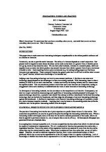
Stress-corrosion cracking (SCC) is the generally accepted term for describing sub-critical cracking of materials under sustained loads (residual or applied) in most liquid and some gaseous environments. Sub-critical cracking of materials in gaseous hydrogen or hydrogen sulphide, and cracking due to internal hydrogen resulting from pre-exposure of materials to hydrogen-bearing environments, are considered to be forms of hydrogen embrittlement (HE) rather than SCC. However, SCC in some materials can involve generation and ingress of hydrogen at crack tips, and characteristics and mechanisms of SCC and HE have a lot in common. Sub-critical cracking in liquid-metal environments is also considered to be a separate phenomenon, usually called liquid-metal embrittlement (LME), but also has a number of similarities to SCC. An understanding of the mechanisms of HE and LME, which are not as complex as SCC, is therefore valuable in understanding SCC, and chapters on the fundamentals of HE (Chapter 2) and LME (Chapter 18) should be consulted in this regard. SCC occurs in a wide range of materials/environments at rates varying from ~10–2 m/s to 1 MeV) ¥ 1025 n/m2 4 6 8 10 12 304 304 304 304 304 316 316 348
24 22 20
HP CP CP CP CP HP CP CP
14
304 304 316 304 316 316 304 Protons 316 Protons
18 16 14 12 10
0
5
10 Dose (dpa)
15
20
17.37 Dose dependence of grain boundary chromium concentration for 300 series austenitic stainless steels irradiated at temperatures about 300°C (Was et al., 2006).
© Woodhead Publishing Limited, 2011
Stress-Raja-17.indd 691
8/18/11 5:00:23 PM
692
Stress corrosion cracking
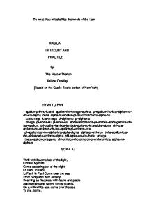
Irradiation generated defects also give rise to an increase in yield strength (Fig. 17.38) and a localization of deformation to channels in the material. An increase in the yield strength from 150–200 MPa up to 750–1000 MPa is commonly observed, with saturation after several dpa. In the mechanismsbased prediction methodology, this irradiation fluence modified yield strength is inserted into a crack tip strain rate algorithm (Eq. 17.8). The final irradiation modification is associated with irradiation induced creep, which leads to stress relaxation in displacement loaded structures, such as welded components, bolts, etc. (Fig. 17.39). Fast neutron irradiation can affect all of the controlling parameters for stress corrosion cracking, and these effects take place over different time and geometry scales. For instance, the neutron flux will have an immediate effect on the corrosion potential, whereas radiation-induced segregation at grain boundaries, increases in yield strength, and relaxation of residual stresses will all take effect over time as fluence increases. With regard to the geometrical aspect, the neutron flux will be attenuated through the thickness dimension of a thick component such as a core shroud; thus, not only is the fluence changing over time, but it is changing at the crack tip as it propagates into the component.
1200
Yield strength (MPa)
1000
800
600 Type Type Type Type Type Type Type Type
400
200
0
0
2
4 6 Dose (dpa)
316 3xx 3xx 304 316 3xx 304 316
SS SS SS SS SS SS SS SS
8
10
17.38 Irradiation dose effects on measured tensile yield strength for several 300-series stainless steels, irradiated and tested at a temperature of about 300°C (Bruemmer et al., 1999; Was et al., 2006).
© Woodhead Publishing Limited, 2011
Stress-Raja-17.indd 692
8/18/11 5:00:23 PM
Prediction of stress corrosion cracking in nuclear power systems
693
250
Stress (MPa)
200
150
100
50
0 0
5
10 Displacement level (dpa)
15
17.39 The effects of radiation-induced creep on load relaxation of stainless steel in a constant displacement (bolt) condition (Van Duysen et al., 1993).
17.4
Prediction of stress corrosion cracking (SCC) in boiling water reactor (BWR) components
The preceding discussion has focused on the dependency of SCC propagation on various system parameters, and the prediction capability for these dependencies is based on an understanding of the mechanism of crack propagation. The comparisons between observation and prediction have been made on data produced in the laboratory. The discussion in this section uses the current mechanistic understanding to predict the SCC behaviour of BWR components (Andresen et al., 1996, 1999b). It is assumed in the subsequent discussion that ‘microscopic’ crack initiation corresponds to the creation of a crack of depth 50 mm, and that this is achieved relatively early in the overall life of the component. The factors behind this assumption were discussed in Section 17.2.3, along with the experimental evidence in Fig. 17.7. Thus, the subsequent crack depth vs time relationship may be calculated by integrating Eq. 17.6 for an appropriately defined alloy/environment system. A major uncertainty in this process is the definition of the residual stress profile adjacent to welds which, as illustrated in Fig. 17.40 can exhibit variability. Mean and bounding values
© Woodhead Publishing Limited, 2011
Stress-Raja-17.indd 693
8/18/11 5:00:23 PM
694
Stress corrosion cracking 28≤ SCH80 pipe–Ranganath analysis Buchalet/Bamford method circumferential crack
50 Upper limit
Mean
30
+ Residual stress Ksi
Stress intensity (ksi √in)
40
30
20
Upper limit +8.1 1.423 Crack depth
142 10 Lower limit
_
Lower limit
Pressure stress 6Ksi Dead weight stress 1 Ksi Thermal stress 6 Ksi 0 0
0.2
0.4
0.6 0.8 1.0 Crack depth (inches)
1.2
1.4
17.40 Variation of stress intensity as crack progresses through wall thickness for 28≤ sch. 80 piping associated with the scatter of residual stress shown in Fig. 17.27(b).
for the residual stress profile can be defined for a given weld geometry, and the corresponding stress intensity factor as a function of defect size can be computed (Buchelet and Bamford, 1976). Figure 17.41 shows the comparison between predicted and observed
© Woodhead Publishing Limited, 2011
Stress-Raja-17.indd 694
8/18/11 5:00:23 PM
Prediction of stress corrosion cracking in nuclear power systems
695
cracking adjacent to welds in 28≤ schedule 80 recirculation piping at two BWR plants with markedly different water purity. The residual stress profile was not known, and thus the prediction can only evaluate the range in crack depth vs time relationships for the range in residual stresses expected for this pipe weld (Fig. 17.40). Despite uncertainties, it is possible to predict the time before cracks will be observed (i.e., when the crack depth exceeds the NDE resolution limit) and to predict the range of crack depths within a given plant piping. The effect of water purity on the cracking susceptibility of these recirculation lines is apparent in Fig. 17.41 in that cracks are predicted and observed after only 32 operating months if the water purity control is poor (i.e., 0.326 mS/cm), but it is predicted that it would be more than 220 months before cracks would be observed in higher purity water (0.15 mS/cm). The specific effect of water purity control on the predicted and observed cracking at a number of plants for 28≤ sch. 80 recirculation lines is further illustrated in Fig. 17.42, where the predicted relationships are based on the mean residual stress profile in Fig. 17.40. A more expanded database is examined in Fig. 17.43 for a series of plants where the time for the crack to penetrate to a quarter wall thickness is recorded as a function of the geometric mean of the water conductivity at those plants. Against each data point is recorded the number of cracks noted. These observed data exhibit a large scatter that is hard to analyze if the data were the only input to the analysis. It is seen, however, that the data are consistent with the mechanisms-based predictions that indicate the theoretical relationships for three combinations of assumed degree of sensitization and residual stress profile. For instance, the earliest failures, which would occur at the worst combination of sensitization and stress, are Theoretical Residual prediction stress Mean Upper limit
Fraction of wall thickness penetrated
0.5 0.4 0.3
Plant A 0.326 µ Scm–1
N.D.T. resolution limit
0.2 Plant B 0.15 µ Scm–1
0.1
20
40
60
80
100 120 140 160 On-line (months)
180
200
240
260
17.41 Theoretical and observed crack depth vs operational time relationships for 28≤ diameter sch. 80 304 stainless steel piping for two boiling water reactors operating at different mean coolant conductivities. Figure adapted from Ford et al. (1988).
© Woodhead Publishing Limited, 2011
Stress-Raja-17.indd 695
8/18/11 5:00:24 PM
696
Stress corrosion cracking
Fraction of wall thickness penetrated
0.5
Theoretical Residual prediction stress Mean Upper limit
0.4 0.3
Browns Ferry-1 0.326 µS/cm
Hatch-1 0.401 µ S/cm
0.2
N.D.T. resolution limit Big Rock Point 0.15 µS/cm
Vermont Yankee 0.216 µS/cm
0.1
20
40
60
80
100 120 140 160 On-line (months)
180
200
240
260
17.42 Theoretical and observed crack depth vs operational time relationships for 28≤ diameter sch. 80 304 stainless steel piping for various boiling water reactors operating at different mean coolant conductivities. Figure adapted from Ford et al. (1988).
10≤–28≤ Dia. sch 80 304 piping in BWR environment Observed data with, in parentheses, the no. of cracks quoted
Conductivity (geo. mean) (µs/cm)
0.5
Theoretical relationships based on ‘Pledge’ code, assuming ECORR = 0 m VSHE 0.4 (42)
(50)
(1)
0.2
0.1
(19)
(2)
0.3
(6) (19) (3) (19) (2)
(2) Dgree of Curve # sresid. sensitizN 1 Mean 15C/cm2 Mean condition 2 Upper 15C/cm2 3 Upper 20C/cm2 Worst condition 20
(6) 1
2 10 3
40 60 80 100 120 140 On-line time (months) for wall penetration, a/t = 0.25
160
17.43 Predicted vs observed relationships between the time for a crack to penetrate to a quarter wall thickness and the plant’s mean coolant conductivity. Figure adapted from Ford et al. (1988).
in fact predicted, whereas the larger number of incidences correspond to the mean conditions of sensitization and stress. Similar predictions may be made for the cracking propensity for different system parameters such as a change in water chemistry (Fig. 17.44) and a change in stainless steel composition (304 vs 316NG vs 321) or the effect
© Woodhead Publishing Limited, 2011
Stress-Raja-17.indd 696
8/18/11 5:00:24 PM
Prediction of stress corrosion cracking in nuclear power systems Next fuel Current observations outage
Fraction of wall thickness
0.5
697
Plant A 28≤ recirculation lines
Current water purity 0.401 µScm–1
0.4
Improved water purity, e.g. 0.15 µScm–1
0.3
0.2
0.1
NDT resolution limit 20
40
60 80 100 120 Operating time (months)
Hydrogen water chemistry e.g. ≤–280 m VSHE 0.1 µScm–1
140
160
17.44 Predicted response of defected piping for defined changes in water chemistry in BWR plant. Figure adapted from Ford et al. (1988).
of surface grinding and its effect on surface residual stresses. Obviously, there will be epistemic uncertainties in the predictions associated with uncertainties in the values of the model parameters (e.g., residual stress, coolant conductivity, corrosion potential, sensitization, etc.), but these can be treated via knowledge of the distributions of these parameters and their input, via a Monte Carlo assessment, into the deterministic algorithm (Eq. 17.6). This was done early on for BWR piping systems (Harris et al., 1986) in the development of the PRAISE-B and PRAISE-CC codes using an empirically derived damage accumulation algorithm rather than the mechanisms-informed algorithm described above. Mechanisms-informed predictions, together with an assessment of the uncertainty in the prediction associated with epistemic uncertainties in the system definition, can define the cracking susceptibility of unirradiated stainless steel components in a specific BWR plant for proposed material, stress or environmental modifications (Ford et al., 1989). There are two basic problems in verifying the prediction capabilities for IASCC of irradiated stainless steel core components in BWRs. The first issue is the definition of the inputs to the prediction model, and these have been recognized above in terms of the effect of the irradiation flux on the corrosion potential, and the effect of fluence on the grain boundary sensitization, the yield strength and the stress relaxation in displacement loaded structures. The second issue is the accuracy of NDE measurements on defected components, which act as confirmation (or denial) of the proposed life prediction model. This latter aspect is significant (Pathania et al., 2009).
© Woodhead Publishing Limited, 2011
Stress-Raja-17.indd 697
8/18/11 5:00:24 PM
698
Stress corrosion cracking
Prediction of IASCC in BWR components, followed by their validation via comparison against observation, can be made even accepting these issues. For instance, an example of a predicted crack depth vs time relationship is shown in Fig. 17.45 for a welded stainless steel core shroud in which the crack depth is predicted to change with time (fluence) in a manner that reflects the time-dependent relaxation in weld residual stress (which decreases the cracking susceptibility) and the increase in grain boundary sensitization (which increases the cracking susceptibility). In this case the sensitization is attributed (Eq. 17.9) to the initial thermally induced chromium depletion at the grain boundary due to the welding process (i.e., 20 C/cm2), plus the additional Cr depletion that occurs with fluence at that particular point in the shroud. Note that this diagram does not show the increase in yield strength with fluence, which will increase the cracking susceptibility due to its effect on the crack tip strain rate. The crack growth rate is not constant but will vary, mirroring these competing effects of stress relaxation, increasing yield strength and grain boundary sensitization, etc. The predicted variation in crack propagation rate with time can become complicated as illustrated in Fig. 17.46, due to the interactions and competing effects of a decrease in susceptibility associated with stress relaxation and Fast neutron fluence ¥1020 ncm–2 (inner surface) 1 2 3
4 35
0.2
Assumed sRES(id) Crack depth (ins)
Assumed EPR(id) 25
0.1
0.05
Calculated crack depth fcorr = +75 mVSHE K = 0.2 µScm–1 ai = 51 µm
20
40
60 80 100 120 Operational time (months)
sRES(id) (ksi)
30
0.15
20
140
160
17.45 Predicted crack depth vs time response for cracks propagating in the beltline weld of a core shroud, illustrating the non-monotonic variation in crack propagation due to the competing effects of fast neutron irradiation on grain boundary sensitization and on residual stress relaxation (Andresen et.al., 1996; Andresen and Ford, 1995).
© Woodhead Publishing Limited, 2011
Stress-Raja-17.indd 698
8/18/11 5:00:24 PM
Prediction of stress corrosion cracking in nuclear power systems
699
H4 shroud beltline weld #J4/5/6v
10–3
304SS, two-sided weld, epr0 = 5 C/cm2 0.3, 0.2, 0.1 µS/cm +0.175 VSHE symmetrical sres profile 3 ¥ 1019 n/cm2-y 10–6
10–4 0.3 0.2 µS/cm 10–5
10–7 0.1
mm/s
Crack velocity (in/h)
5 ¥ 10–5 in/h
10–8 10
–6
sres with + 10 ksi above nominal (shroud 4) 10–7
0
100
200 Time (months)
300
10–9 400
17.46 Predicted variation in crack propagation rate in an irradiated core shroud belt line weld as a function of time (fluence) indicating that the NRC disposition propagation rates cannot be sustained.
an increase in susceptibility associated with grain boundary sensitization and increasing yield stress. As indicated in Fig. 17.46, these crack propagation rate responses will change with water conductivity (purity). They will also change with the initial degree of thermal sensitization (e.g., the use of L-grade steels), extent of surface cold work, position in the reactor core (e.g., flux), etc. A comparison is given in Fig. 17.47 between the observed and predicted crack depths adjacent to a horizontal beltline weld in a BWR core shroud, where the observations have been made during consecutive reactor outages. For the reasons given above, there is a range in observed crack depths adjacent to the horizontal welds due to the uncertainty in NDE measurements. It is also apparent that there is a range in predicted crack depths due to the uncertainty in defining the residual stress profile both around the circumference of the weld as well as through the 2≤ thickness of the shroud. Given these uncertainties, the only rational way of assessing the overall accuracy of the prediction methodology is to compare the ranges in observed and predicted crack depths for different welds and stainless steels. This comparison is made in Fig. 17.48 for various BWR core shroud welds
© Woodhead Publishing Limited, 2011
Stress-Raja-17.indd 699
8/18/11 5:00:24 PM
700 1
Stress corrosion cracking sres with +15 ksi above nominal
1.25 in thick 304SS, 2-sided weld 0.15 µS/cm, EPR0 = 0 C/cm2 Symmetrical sres profile
0.8
Stepped thru-wall flux 5 ¥ 1019 n/cm2-y at ID
Crack depth (in)
+0.20 VSHE 0.6 sres with + 10 ksi above nominal 0.4
0.2
Indication #4: Prior UT Current average Current maximum
0 0
Boat sample
100
200 Time (months)
300
400
17.47 Crack length vs time predictions and observations for a Type 304 stainless steel core shroud with multiple inspections and multiple cracks (Andresen et al., 1989; Andresen and Ford, 1995).
Pledge predicted crack depth (ins)
1.6
304 H-3
1.2
304 H-6 0.8 304 H-4 304 H-4 0.4
0
304 H-3
0
304 H-4
304 L 0.4 0.8 1.2 Observed crack depth (ins)
1.6
17.48 Comparison of observed and predicted crack depth for a number of BWR core shrouds (Andresen et al., 1989; Andresen and Ford, 1995).
© Woodhead Publishing Limited, 2011
Stress-Raja-17.indd 700
8/18/11 5:00:24 PM
Prediction of stress corrosion cracking in nuclear power systems
701
manufactured with different steels (Type 304, 304L). Over this population the agreement between observation and prediction is reasonable, given the uncertainties in observation and definition of the system.
17.5
Conclusions
Prediction of EAC can be made in many ways, ranging from simple estimation based on plant history, to empirical correlation with engineering parameters, to quantitative predictions based on knowledge of the processes and mechanisms. The ideal case is a mechanistic framework that permits interpretation, quantitative description of interdependencies and anticipation/ extrapolation of new variables and their interactions. Such fundamental approaches must be validated with detailed laboratory and plant data. Provided that this is done then the mechanistically informed approach to life prediction acts as a powerful underpinning for the mitigation actions that are robust and fundamentally valid. For stainless steels in BWR, environments in BWRs, such mitigation actions have included material (e.g., control of grain boundary sensitization), reduction in tensile stress, and especially control of certain anionic impurities and lowering the corrosion potential (by, for instance, ‘Hydrogen Water Chemistry’ and ‘Noble Metal Technology’). These latter approaches are widely accepted and used in the BWR fleet worldwide (Cowan, 1994; Andresen et al., 2003a, 2007; Gordon, 1984a, 1984b; Gordon et al., 1983; Hettiarachchi, 2001 2003, 2005; Hettiarachchi et al., 1995a, 1995b, 1997, 2009; EPRI, 2000, 2004; Kim et al., 2007).
17.6
Future trends
Major progress in the prediction of EAC will depend on improvements in the quality and reproducibility of experimental data, especially SCC data (both initiation and growth). While a breakthrough in the conceptual, mechanistic description of EAC cannot be discounted, there are more ideas and concepts than there are definitive data to support or refute a given approach. Isolated, detailed observations, such as of tight SCC tips, raise qualitative questions about mechanisms, but they have not provided a definitive insight into the cracking mechanism. For the relatively narrow conditions that comprise EAC of austenitic stainless steels (and nickel alloys) in high temperature LWR coolants, it is reasonable to propose that the controlling processes and mechanisms of EAC are common. As these common elements are more clearly defined and quantified, and their interdependencies understood, the ability to predict all forms of EAC, including environmental effects on fracture, will improve. A fundamental element will be definitive and accurate experimental data.
© Woodhead Publishing Limited, 2011
Stress-Raja-17.indd 701
8/18/11 5:00:24 PM
702
17.7
Stress corrosion cracking
Sources of further information
There are many excellent proceedings and reviews of EAC in structural materials in LWR water, and the reader is encouraged to examine reviews and individual papers in the Proceedings of the First to Fourteenth International Conference on Environmental Degradation of Materials in Nuclear Power Systems – Water Reactors. Additional details of the behavior and prediction of EAC can be found in publications such as Ford and Andresen (1994), Andresen (2010) and Ford et al. (2006). These sources are listed among the references.
17.8
References
Akashi M. and Nakayama G. (1995), ‘Stress Corrosion Crack Initiation Process Model for BWR Plant Materials’ in Plant Aging and Life Prediction of Corrodible Structures, Eds T. Shibata and T. Shoji, Sapporo, pp. 99–106. Ando M. and Nakata K. (2007), ‘Crack Growth Rate Behavior of Low Carbon Stainless Steels of Hardened Heat Affected Zone in PLR Piping Weld Joints’, Proc. 13th Int. Symp. on Environmental Degradation of Materials in Nuclear Power Systems – Water Reactors, Whistler, BC, August, 2007. Andresen P.L. (1980), ‘The Effects of Surface Preparation, Stress and Deaeration on the Stress Corrosion Cracking of Type 304 Stainless Steel in Simulated BWR Start-Up Cycles’, Proc. Seminar on Countermeasures for Pipe Cracking in BWRs, Vol. 3, January 22–24, EPRI Reports WS 79-174, May. Andresen P.L. (1983), ‘The Effects of Aqueous Impurities on Intergranular Stress Corrosion Cracking of Sensitized 304 Stainless Steel’, EPRI Report NP-3384, November. Andresen P.L. (1984), ‘Laboratory Results on Effects of Oxygen Control during a BWR Start up on the IGSCC of 304 Stainless Steel’, Proc. 2nd Seminar on Countermeasures for Pipe Cracking in BWRs, November 15–18, EPRI Report NP-3684-SR Sept. 1984, Vol. 2, p. 12–1. Andresen P.L. (1987), ‘Modeling of Water and Material Chemistry Effects on Crack Tip Chemistry and Resulting Crack Growth Kinetics’, Proc. 3rd Int. Conf. Environmental Degradation of Materials in Nuclear Power Systems – Water Reactors, Traverse City, AIME, pp. 301–314. Andresen P.L. (1991), ‘Effects of Specific Anionic Impurities on Environmental Cracking of Austenitic Materials in 288°C Water’, Proc. 5th Int. Symp. on Environmental Degradation of Materials in Nuclear Power Systems – Water Reactors, Monterey, August 25–29, 1991, Eds D. Cubicciotti, E. Simonen, American Nuclear Society, pp. 209–218. Andresen P.L. (1992a), ‘Effects of Zinc Additions on the Crack Growth Rate of Sensitized Stainless Steel and Alloys 600 and 182 in 288C Water’, Paper 72, Water Chemistry of Nuclear Reactor Systems 6, BNES, London, 1992. Andresen P.L. (1992b), ‘Effect of Temperature on Crack Growth Rate in Sensitized Type 304 Stainless Steel and Alloy 600’, Paper 89, NACE Corrosion/92, Nashville, April 1992. Andresen P.L. (1993a), ‘Specific Anion and Corrosion Potential Effects on Environmentally Assisted Cracking in 288C Water’, GE-CRD Report 93CRD215, December.
© Woodhead Publishing Limited, 2011
Stress-Raja-17.indd 702
8/18/11 5:00:24 PM
Prediction of stress corrosion cracking in nuclear power systems
703
Andresen P.L. (1993b), ‘Effects of Dissolved Silica on the Crack Growth Rate of Sensitized Stainless Steel’, GE-CRD Report 93CRD212, December. Andresen P.L. (1993c), ‘The Effects of Nitrate on the Stress Corrosion Cracking of Sensitized Stainless Steel at 288C’, GE-CRD Report 93CRD213, December. Andresen P.L. (1995a), ‘Effects of Nitrate on the Stress Corrosion Cracking of Sensitized Stainless Steel in High Temperature Water’, Proc. 7th Int. Symp. on Environmental Degradation of Materials in Nuclear Power Systems – Water Reactors, Breckenridge, August 7–10, 1995. Eds R. Gold, A. McIlree, National Association of Corrosion Engineers, pp. 609–619. Andresen P.L. (1995b), ‘Application of Noble Metal Technology for Mitigation of Stress Corrosion Cracking in BWRs’, Proc. 7th Int. Symp. on Environmental Degradation of Materials in Nuclear Power System – Water Reactors, NACE, Houston, TX, p. 563. Andresen P.L. (1997), ‘Effects of Flow Rate on SCC Growth Rate Behavior in BWR Water’, Proc. 8th Int. Symp. on Environmental Degradation of Materials in Nuclear Power Systems – Water Reactors, Amelia Island, Eds A. McIlree, S. Bruemmer, American Nuclear Society, August 10–14, 1997, pp. 603–614. Andresen P.L. (1999), ‘Stress Corrosion Cracking Testing and Quality Considerations’, Proc. 9th Int. Symp. on Environmental Degradation of Materials in Nuclear Power Systems – Water Reactors, Newport Beach, August 1–5, 1999. Eds S. Bruemmer, F.P. Ford, The Metallurgical Society, pp. 411–421. Andresen P.L. (2002), ‘Similarity of Cold Work and Radiation Hardening in Enhancing Yield Strength and SCC Growth of Stainless Steel in Hot Water’, Corrosion/02, Paper 02509, NACE. Andresen P.L. (2010), ‘Stress Corrosion Cracking in Austenitic Stainless Steels’, in Understanding and Mitigating Ageing in Nuclear Power Plants, Ed. P G Tipping, Woodhead Publishing, Cambridge. Andresen P.L. and Angeliu T.M. (1995), ‘Effects of Zinc Additions on the Stress Corrosion Crack Growth Rate of Sensitized Stainless Steel, Alloy 600 and Alloy 182 Weld Metal in 288C Water’, Paper 409, Corrosion/95, NACE, Orlando, FL, March. Andresen P.L. and Ford F.P. (1995), ‘Modeling and Prediction of Irradiation Assisted Cracking’, Proc. 7th Int. Symp. on Environmental Degradation of Materials in Nuclear Power Systems – Water Reactors, Breckenridge, August 7–10, 1995. Eds R. Gold, A. McIlree. National Association of Corrosion Engineers, pp. 893–908. Andresen P.L. and Morra M.M. (2005), ‘Effects of Si on SCC of Irradiated and Unirradiated Stainless Steels and Nickel Alloys’, Proc. 12th Int. Symp. on Environmental Degradation of Materials in Nuclear Power Systems – Water Reactors, TMS, Snowbird, August 2005, pp. 87–108. Andresen P.L., Ford F.P., Murphy S.M. and Perks J.M. (1989), ‘State of Knowledge of Irradiation Effects on EAC in LWR Core Materials’, Proc. 4th Int. Symp. on Environmental Degradation of Materials in Nuclear Power Systems – Water Reactors, Jekyll Island, August 6–10, 1989, Eds D. Cubicciotti, E. Simonen, National Association of Corrosion Engineers, pp. 1.83–1.121. Andresen P.L., Vasatis I.P. and Ford F.P. (1990), ‘Behavior of Short Cracks in Stainless Steel at 288°C’, Paper 495, NACE Conference, Las Vegas, April. Andresen P.L., Ford F.P., Higgins J.P., Suzuki I., Koyama M., Akiyama M., Okubo Y., Mishima Y., Hattori S., Anzai H., Chujo H. and Kanazawa Y. (1996), ‘Life Prediction of Boiling Water Reactor Internals’, Proc. ICONE-4 Conference, ASME. Andresen P.L., Gott K. and Nelson J.L. (1999a), ‘Stress Corrosion Cracking of Sensitized
© Woodhead Publishing Limited, 2011
Stress-Raja-17.indd 703
8/18/11 5:00:24 PM
704
Stress corrosion cracking
Stainless Steel – a Five Lab Round Robin’, Proc. 9th Int. Symp. on Environmental Degradation of Materials in Nuclear Power Systems – Water Reactors, Newport Beach, CA, August 1–5, 1999, Eds S. Bruemmer, F.P. Ford, The Metallurgical Society, pp. 423–433. Andresen P.L., Ford F.P., Angeliu T.M., Solomon H.D. and Cowan R.L. (1999b), ‘Prediction of Environmentally-Assisted Cracking and its Relevance to Life Management in BWRs’, Proc. 9th Int. Symp. on Environmental Degradation of Materials in Nuclear Power Systems – Water Reactors, Newport Beach, CA, August 1–5, 1999, Eds S. Bruemmer, F.P. Ford, The Metallurgical Society, pp. 373–381. Andresen P.L., Emigh P.E. and Young L.M. (2002), ‘Mechanistic and Kinetic Role of Yield Strength/Cold Work/Martensite, H2, Temperature, and Composition on SCC of Stainless Steels’, Proc. 10th Anniversary INSS Symp. on SCC in Nuclear Power Systems, Osaka, Japan, May. Andresen P.L., Diaz T.P. and Hettiarachchi S. (2003a), ‘Effect on Stress Corrosion Cracking of Electrocatalysis and Its Distribution Within Cracks’, Proc. 11th Int. Conf. on Environmental Degradation of Materials in Nuclear Power Systems – Water Reactors, Skamania Lodge, August 5–9, 2003, Eds G. Was, L. Nelson, American Nuclear Society. Andresen P.L., Emigh P.W., Morra M.M. and Horn R.M. (2003b), ‘Effects of Yield Strength, Corrosion Potential, Stress Intensity Factor, Silicon and Grain Boundary Character on SCC of Stainless Steels’, Proc. 11th Int. Conf. on Environmental Degradation of Materials in Nuclear Power Systems – Water Reactors, Skamania Lodge, August 5–9, 2003, Eds G.S. Was, J.L. Nelson, American Nuclear Society, pp. 816–832. Andresen P.L., Kim Y-J., Diaz T.P. and Hettiarachchi S. (2007), ‘Mitigation of SCC by On-line NobleChem’, Proc. 13th Int. Conf. on Environmental Degradation of Materials in Nuclear Power Systems – Water Reactors, Whistler, August 20–24, 2007, Eds P. King, T. Allen, The Canadian Nuclear Society. Angeliu T.M. (1995), ‘The Effect of Zinc Additions on the Oxide Rupture Strain and Repassivation Kinetics of Fe-Base Alloys in 288C Water’, Paper 411, Corrosion/95, NACE, Orlando, FL, March. Angeliu T.M., Andresen P.L., Sutliff J.A. and Horn R.M. (1999), ‘Intergranular Stress Corrosion Cracking of Unsensitized Stainless Steels in BWR Environments’, Proc. 9th Int. Symp. on Environmental Degradation of Materials in Nuclear Power Systems – Water Reactors, Newport Beach, CA, August 1–5, 1999, Eds S. Bruemmer, F.P. Ford, The Metallurgical Society, pp. 311–318. Beck T.R. (1974), ‘Reactions and Kinetics of newly generated titanium surfaces and relevance to stress corrosion cracking’, Corrosion 30, p. 408. Bose A. and De P.K. (1987), ‘An EPR Study on the Influence of Prior Cold Work on the Degree of Sensitization of AISI 304 Stainless Steel’, Corrosion 43, pp. 624–631. Briant C.L. (1982), ‘Effects of Nitrogen and Cold Work on the Sensitization of Austenitic Stainless Steels’, EPRI Report NP-2457, June. Brown K.S. and Gordon G.M. (1987), ‘Effects of BWR Coolant Chemistry on Propensity for IGSCC Initiation and Growth in Creviced Reactor Internals Components’, Proc. 3rd Int. Symp. on Environmental Degradation of Materials in Nuclear Power Systems – Water Reactors, Traverse City, August 30–Sept 3, 1987, Eds G.J. Theus, W. Berry, The Metallurgical Society, pp. 243–248. Bruemmer S.M., Charlot L.A. and Arey B.W. (1988a), ‘Sensitization Development in Austenitic Stainless Steel: Correlation Between STEM-EDS and EPR Measurements’, Corrosion 44, pp. 328–333.
© Woodhead Publishing Limited, 2011
Stress-Raja-17.indd 704
8/18/11 5:00:24 PM
Prediction of stress corrosion cracking in nuclear power systems
705
Bruemmer S.M. Charlot L.A. and Atteridge D.G. (1988b), ‘Sensitization Development in Austenitic Stainless Steel: Measurement and Prediction of Thermochemical History Effects’, Corrosion 44, pp. 427–434. Bruemmer S.M., Arey B.W. and Charlot L.A. (1993), ‘Grain Boundary Chromium Concentration Effects on the IGSCC and IASCC of Austenitic Stainless Steels’, Proc. 6th Int. Symp. on Environmental Degradation of Materials in Nuclear Power Systems – Water Reactors, San Diego, CA, August 1–5, 1993, Eds E. Simonen, R. Gold, National Association of Corrosion Engineers, pp. 227–287. Bruemmer S.M. Cole J.I., Garner F.A., Greewood L.R., Hamilton M.L., Reid B.D., Simonen E.P., Lucas G.E., Was G.S., Andresen P.L. and Pettersson K. (1996), ‘Critical Issues Reviews for the Understanding and Evaluation of Irradiation Assisted Stress Corrosion Cracking’, EPRI TR-107159, November. Bruemmer S.M., Simonen E.P., Scott P.M., Andresen P.L., Was G.S. and Nelson J.L. (1999),‘Radiation-induced materials changes and susceptibility to intergranular failure of light-water-reactor core internals’, J. Nucl. Mater., 274, pp. 299–314. Buchelet C.B. and Bamford W.H. (1976), ‘Stress Intensity Factor Solutions for Continuous Surface Flaws in Reactor Pressure Vessels’, in Mechanics of Crack Growth, ASTM STP S90 American Society for Testing and Materials, pp. 385–402. Chrenko R.M. (1980), ‘Residual Stress Measurements on Type 304 Stainless Steel Welded Pipes’, in ‘EPRI, Proceedings of Seminar on Countermeasures for Pipe Cracking in BWRs. Volume 2, January 22–24, 1980, EPRI Reports WS 79-174. Clarke W.L. (1980), ‘The ECP Method for Detecting Sensitization in Stainless Steels’, NUREG/CR-1095, February 1980. Clarke W.L., Cowan R.L. and Walker W.L. (1978), ‘Comparative Methods for Measuring Degree of Sensitization in Stainless Steels’, ASTM STP 656. Cohen P. (1969), Water Coolant Technology of Power Reactors, Gordon and Breach Science Publishers, 1969. Congleton J., Zheng W. and Hua H. (1990), ‘The stress corrosion cracking behaviour of annealed 316 stainless steel in low oxygen 5 ppm chloride content water at 300°C, Corrosion Science 27(6/7), p. 555–567. Cowan R.L. (1994), ‘Optimizing Water Chemistry in US Boiling Water Reactors’, VGB Conference Plant Chemistry Essen, Germany, October. Davis R.B. and Indig M.E. (1983), ‘The Effect of Aqueous Impurities on the Stress Corrosion Cracking of Austenitic Stainless Steel in High Temperature Water’, Paper 128, Corrosion/83, Anaheim, CA, National Association of Corrosion Engineers, April. Dawson J.K. and Sowden R.G. (1963), ‘Chemical Aspects of Nuclear Reactors’, in Water Cooled Reactors, Vol. 2, Butterworths. Eason E. and Shusto L.M. (1986), ‘Analysis of Cracking in Small Diameter BWR Piping’, EPRI NP-4394, EPRI, Palo Alto. Eason E.D., Pathania R. and Shoji T. (2005), ‘Evaluation of the Fracture Research Institute Theoretical Stress Corrosion Cracking Model’, Proc. 12th Int. Conf. on Environmental Degradation of Materials in Nuclear Power Systems – Water Reactors, Skamania Lodge, August 5–9, 2005, Eds L. Nelson, P. King, The Metallurgical Society, pp. 145–154. EPRI (1985), ‘BWR Coolant Impurity Identification Study’, EPRI Report NP-4156, August. EPRI (1992a), ‘BWR Chromium Chemistry’, EPRI Report TR-100792, October. EPRI (1992b), ‘The Effect of Chromates on IGSCC in BWR Environments’, EPRI Report TR-100853, July.
© Woodhead Publishing Limited, 2011
Stress-Raja-17.indd 705
8/18/11 5:00:24 PM
706
Stress corrosion cracking
EPRI (1996), ‘Evaluation of Crack Growth in BWR Stainless Steel RPV Internals (BWRVIP-14)’, EPRI report TR-105873, March. EPRI (1997), ‘BWR Vessel and Internals Project ‘IGSCC in BWRs during Transient Conditions’, EPRI Report BWR VIP-40, TR-107093, August. EPRI (1999), ‘BWR Vessel and Internals Project ‘Effects of Flow Rate on Intergranular Stress Corrosion Cracking and Electrochemical Corrosion Potential’, EPRI Report VIP-64, TR-112314, March. EPRI (2000), ‘BWR Water Chemistry Guidelines – 2000 Revision’, EPRI Report TR103515-R2, February. EPRI (2004), ‘BWR Water Chemistry Guidelines – 2004 Revision’, EPRI Technical Report TR-1008192, October, VIP-130. Fong C. (2007), ‘Flow Rate Effects on the Stress Corrosion Cracking of Sensitized Stainless Steels in BWR Environments’, Proc. 13th Int. Conf. on Environmental Degradation of Materials in Nuclear Power Systems – Water Reactors, Whistler, August 20–24, 2007, Eds P. King, T. Allen, The Canadian Nuclear Society. Ford F.P. (1982a), ‘Mechanisms of Environmental Cracking Peculiar to the Power Generation Industry’, Report NP2589, EPRI, Palo Alto, September. Ford F.P. (1982b), ‘Stress Corrosion Cracking’, in Corrosion Processes, Ed. R.N. Parkins, Applied Science. Ford F.P. (1988), ‘The Crack Tip System and its Relevance to the Prediction of Cracking in Aqueous Environments’, Proc. 1st Inter. Conf. on Environmentally Assisted Cracking of Metals, Kohler, WI, October 2–7 1988, Eds R. Gangloff and B. Ives, NACE, pp. 139–165. Ford F.P. (1996), ‘Quantitative Prediction of Environmentally Assisted Cracking’, Corrosion 52, pp. 375–395. Ford F.P. (2007), ‘Technical and Management Challenges Associated with Structural Materials Degradation in Nuclear Reactors in the Future’, Proc. Int. Conf. Environmental Degradation of Materials in Nuclear Power Systems, Whistler, British Columbia, August 19–23, 2007, Canadian Nuclear Society. Ford F.P. and Andresen P.L. (1994), ‘Corrosion in Nuclear Systems: Environmentally Assisted Cracking in Light Water Reactors’, in Corrosion Mechanisms, Eds P. Marcus and J. Ouder, Marcel Dekker, pp. 501–546. Ford F.P. and Povich M.J. (1979), ‘Effect of Oxygen and Temperature Combinations on the Stress Corrosion Cracking of Sensitized Type 304 Stainless Steel’, Corrosion 35, 569. Ford F.P., Taylor D.F., Andresen P.L. and Ballinger R.G. (1987), ‘Corrosion Assisted Cracking of Stainless Steel and Low Alloy Steels in LWR Environments’, Report NP5064S, EPRI, Palo Alto, February. Ford F.P., Andresen P.L., Benz M.G. and Weinstein D. (1988), ‘On-Line BWR Materials Monitoring and Plant Component Lifetime Prediction’, Proc. Nuclear Power Plant Life Extension, Snowbird, UT, June 1988, American Nuclear Society, Vol. 1, pp. 355–366. Ford F.P., Andresen P.L., Solomon H.D., Gordon B.M., Ranganath S., Weinstein D. and Pathania R. (1989), ‘Application of Water Chemistry Control, On-Line Monitoring and Crack Growth Rate Models for Improved BWR Materials Performance’, Proc. 4th Int. Symp. on Environmental Degradation of Materials in Nuclear Power Systems – Water Reactors, Jekyll Island August 6–10, 1989, Eds D. Cubicciotti, E. Simonen, National Association of Corrosion Engineers, pp. 4.26-4.51. Ford F.P., Gordon B.M. and Horn R.M. (2006), ‘Corrosion in Boiling Water Reactors’,
© Woodhead Publishing Limited, 2011
Stress-Raja-17.indd 706
8/18/11 5:00:24 PM
Prediction of stress corrosion cracking in nuclear power systems
707
in ASM Materials Handbook Vol 13C, Corrosion: Environments and Industries, pp. 341–361. Fruzzetti K.P. and Blok J. (2005), ‘A Review of the EPRI Chemistry Guidelines’, Proc. Int. Conf. on Water Chemistry of Nuclear Reactor Systems, San Francisco. Gao Y.C. and Hwang K.C. (1981), ‘Elastic Plastic Fields in Steady Crack Growth in a Strain Hardening Material’, Proc. 5th Int. Conf. on Fracture, pp. 669–682. Gordon B.M. (1980), ‘The Effect of Chloride and Oxygen on Stress Corrosion Cracking of Stainless Steel; Review of Literature’, Materials Performance 19(4), p. 29. Gordon B.M. (1984a), ‘Laboratory Studies of Materials Performance in Hydrogen Water Chemistry’, Paper presented at EPRI Seminar on BWR Corrosion, Chemistry and Radiation Control, Palo Alto, CA, Electric Power Research Institute, October. Gordon B.M. (1984b), ‘Corrosion and Corrosion Control in BWRs’, GE Class 1 Report NEDO-24819A, December. Gordon B.M., Cowan R.L., Jewett C.W. and Pickett A.E. (1983), ‘Mitigation of Stress Corrosion Cracking through Suppression of Radiolytic Oxygen’, Proc. 1st Int. Symp. on Environmental Degradation of Materials in Nuclear Power Systems – Water Reactors, Myrtle Beach, August 22–25, 1983, Eds J. Roberts, W Berry, National Association of Corrosion Engineers, pp. 893–932. Gordon G.M. and Brown K.S. (1989), ‘Dependence of Creviced BWR Component IGSCC Behavior on Coolant Chemistry’, Proc. 4th Int. Symp. on Environmental Degradation of Materials in Nuclear Power Systems – Water Reactors, Jekyll Island, August 6–10, 1989, Eds D. Cubicciotti, E. Simonen, National Association of Corrosion Engineers, pp. 14.46–14.62. Gott K. (1999), ‘The History of Cracking in the Reactor Coolant Pressure Boundary of Swedish BWR Plants’, Proc. 9th Int. Symp. on Environmental Degradation of Materials in Nuclear Power Systems – Water Reactors, Newport Beach, August 1–5, 1999, Eds S. Bruemmer, F.P. Ford, The Metallurgical Society. Gott K. (2001), ‘Cracking Data Base as a Basis for Risk Informed Inspection’, Proc. 10th Int. Conf. on Environmental Degradation of Materials in Nuclear Power Systems – Water Reactors, Lake Tahoe, August 5–9, 2001, Eds F.P. Ford, G.S. Was, National Association of Corrosion Engineers. Hale D.A. (1986), ‘The Effect of BWR Startup Environments on Crack Growth in Structural Alloys’, Trans ASME 108, p. 44. Hale D.A. (1991), ‘BWR Coolant Impurities Program at Peach Bottom Units 2&3’, EPRI Report NP-7310-L, May. Hale D.A. and Pickett A.E. (1984), ‘Material Performance in a Startup Environment’, Proc. 2nd Seminar on Countermeasures for Pipe Cracking in BWRs, November 15–18, 1983, EPRI Report NP-3684-SR, Vol. 2, pp. 13–1, September. Harris D.O., Dedia D.D., Eason E.D. and Patterson S.D. (1986), ‘Probability of Failure in BWR Reactor Coolant Piping; Probabilistic Treatment of Stress Corrosion Cracking in 304 and 316NG BWR Piping Weldments’, NUREG/CR-4792, December. Hazelton W.S. and Koo W.H. (1988), ‘Technical Report on Materials Selection and Processing Guidelines for BWR Coolant Pressure Boundary Piping’, NUREG-0313 Rev.2, USNRC, January. Hettiarachchi S. (2001), ‘NobleChem from Concept to Operating Commercial Power Plant Application’, Proc. 10th Int. Conf. on Environmental Degradation of Materials in Nuclear Power Systems – Water Reactors, Lake, Tahoe August 5–9, 2001, Eds F.P. Ford, G.S, Was, National Association of Corrosion Engineers. Hettiarachchi S. (2003), ‘BWR SCC Mitigation Strategies and their Effectiveness’,
© Woodhead Publishing Limited, 2011
Stress-Raja-17.indd 707
8/18/11 5:00:25 PM
708
Stress corrosion cracking
Proc. 11th Int. Conf. on Environmental Degradation of Materials in Nuclear Power Systems – Water Reactors, Skamania Lodge, August 5–9, 2003, Eds G.S. Was, J.L. Nelson, American Nuclear Society. Hettiarachchi S. (2005), ‘BWR SCC Mitigation Experiences with Hydrogen Water Chemistry’, Proc. 12th Int. Conf. on Environmental Degradation of Materials in Nuclear Power Systems – Water Reactors, Skamania Lodge, August 5–9, 2005, Eds J.L. Nelson, P. King, The Metallurgical Society, pp. 685. Hettiarachchi S., Wozadlo G.P. and Diaz T.P. (1995a), ‘Influence of Zinc Additions on the Intergranular Stress Corrosion Crack Initiation and Growth of Sensitized Stainless Steel in High Temperature Water’, Paper 410, Corrosion/95, NACE, Orlando, FL, March. Hettiarachchi S., Wozadlo G., Andresen P.L., Diaz T. and Cowan R.L. (1995b), ‘The Concept of Noble Metal Addition Technology for IGSCC Mitigation of Structural Materials’, Proc. 7th Int. Symp. on Environmental Degradation of Materials in Nuclear Power Systems – Water Reactors, Breckenridge, August 7–10, 1995, Eds R. Gold, A. McIlree, National Association of Corrosion Engineers, pp. 735–746. Hettiarachchi S., Law R.J., Diaz T.P., Cowan R.L., Keith W. and Pathania R.S. (1997), ‘The First In-Plant Demonstration of Noble Metal Chemical Addition (NMCA) Technology for IGSCC Mitigation of BWR Internals’, Proc. 8th Int. Symp. on Environmental Degradation of Materials in Nuclear Power Systems – Water Reactors, Amelia Island, August 10–14, 1997, Eds A. McIlree, S. Bruemmer, American Nuclear Society, pp. 535–543. Hettiarachchi S., Horn R.M., Andresen P.L. and Kim Y.J. (2009), ‘Electrochemical Corrosion Potential (ECP) Reduction and Crack Mitigation Experiences with NobleChem™ and On-Line NobleChem™’, Proc. 14th Int. Conf. on Environmental Degradation of Materials in Nuclear Power Systems – Water Reactors, Virginia Beach, August 24–28, 2009, Eds T. Allen, J. Busby, American Nuclear Society. Hickling J. (1994), ‘Evaluation of Acceptance Criteria for Data on Environmentally Assisted Cracking in Light Water Reactors’, SKI Report 94.14, September. Hickling J. (2005), ‘Status Review of Initiation of Environmentally Assisted Cracking and Short Crack Growth’, EPRI Report # 1011788, December. Horn R.M., Gordon G.M., Ford F.P. and Cowan R.L. (1997), ‘Experience and Assessment of Stress Corrosion Cracking in L-Grade Stainless Steel BWR Internals’, Nuclear Engineering and Design 174, pp. 313–325. Indig M. (1980), ‘Controlled Potential Simulation of Deaerated and Non-Dearated Startup’, Proc. Seminar on Countermeasures for Pipe Cracking in BWRs, Vol. 3, January 22–24, 1980, EPRI Reports WS 79–174, May. Indig M.E., Gordon G.M. and Davis R.B. (1983), ‘The Role of Water Purity on Stress Corrosion Cracking’, Proc. 1st Int. Symp. on Environmental Degradation of Materials in Nuclear Power Systems – Water Reactors, Myrtle Beach, August 22–25, 1983, Eds J. Roberts, W Berry, National Association of Corrosion Engineers, pp. 506–531. Jacobs A.J., Hale D.A. and Siegler M. (1986), ‘Unpublished GE data. Jiang X.C. and Staehle R.W. (1997), ‘Application of the Chemical–Mechanical Correlation Equation for SCC’, Proc. 8th Int. Symp. on Environmental Degradation of Materials in Nuclear Power Systems – Water Reactors, Amelia Island, August 10–14, 1997, Eds A. McIlree, S. Bruemmer, American Nuclear Society, pp. 582–596. Kawakubo T., Hishida M. and Arii M. (1980), ‘A Model for Intergranular Stress Corrosion Cracking Initiation in BWR Pipes and the Virtue of Startup Deaeration’, Proc. Seminar on Countermeasures for Pipe Cracking in BWRs, Vol. 3, January 22–24, 1980, EPRI Reports WS 79–174, May. © Woodhead Publishing Limited, 2011
Stress-Raja-17.indd 708
8/18/11 5:00:25 PM
Prediction of stress corrosion cracking in nuclear power systems
709
Kilian R., Brummer G., Ilg U., Maier V., Teichmann H. and Wachter O. (1995), ‘Characterization of Sensitization and Stress Corrosion Behaviour of Stabilized Stainless Steels under BWR Conditions’, Proc. 7th Int Symp. on Environmental Degradation of Materials in Nuclear Power Systems – Water Reactors, Breckenridge, August 7–10, 1995, Eds R. Gold, A. McIlree, National Association of Corrosion Engineers. Kilian R., Hoffmann H., Ilg U., Küster K., Nowak E., Wesseling U. and Widera M. (2005), ‘German Experience with Intergranular Cracking in Austenitic Piping in BWRs and Assessment of Parameters Affecting the In-Service IGSCC Behaviour Using an Artificial Neural Network’, Proc. 12th Int. Conf. on Environmental Degradation of Materials in Nuclear Power Systems – Water Reactors, Skamania Lodge, August 5–9, 2005, Eds L. Nelson, P. King, The Metallurgical Society, pp. 803–812. Kim Y.J. and Andresen P.L. (2003), ‘Data Quality, Issues and Guidelines for ECP Measurements in High Temperature Water’, Corrosion 59, pp. 584–596. Kim Y.J., Andresen P.L., Hettiarachchi S. and Diaz T.P. (2007), ‘Effect of Variations in Noble Metal Chemical Addition Process on Electrochemical Catalytic Response in High Temperature Water’, Proc. 13th Int. Conf. on Environmental Degradation of Materials in Nuclear Power Systems – Water Reactors, Whistler, August 20–24, 2007, Eds P. King, T. Allen, The Canadian Nuclear Society. Klepfer H.H. et al. (1975), ‘Investigation of Cause of Cracking in Austenitic Stainless Steel Piping’, NEDO-21000, General Electric, July. Kurtz R.J. (1983), ‘Evaluation of BWR Resin Intrusions on Stress Corrosion Cracking of Reactor Structural Materials’, EPRI Report NP-3145, June. Lin C.C. (1985), ‘An Overview of Radiation Chemistry in Reactor Coolants’, Proc. 2nd Int. Symp. on Environmental Degradation of Materials in Nuclear Power Systems – Water Reactors, Monterey, September 9-12, 1985, Eds J. Roberts, J. Weeks, American Nuclear Society, pp. 160–172. Lin C.C., Kim Y.J., Niedrach L. and Ramp K.S. (1996), ‘Electrochemical Potential Models for BWR Applications’, Corrosion 52, p. 618. Ljungberg L.G., Cubicciotti D. and Troll M.E. (1989), ‘The Effect of Sulfate on Environmental Cracking in BWRs Under Constant Load or Fatigue’, Paper 617, Corrosion/89, NACE, New Orleans, LA, April. Ljungberg L.G., Ortnas A., Stigenberg M., Hofling C.G., Sahlberg A and Moller J. (1995), ‘Stress Corrosion Cracking of Alloys 600 and 182 in BWRs’, EPRI Report TR-104972, May. Logan H.L. (1952), ‘Film Rupture Mechanism of Stress Corrosion’, J. Natl. Bur. Stand 48, p. 99. Medoff J. (1996), ‘Status Report; Intergranular Stress Corrosion Cracking of BWR Core Shrouds and other Internals Components’, USNRC NUREG-1544, March. Molander A., Bengtsson B., Jansson C., Takagi J. and Sakamoto H. (1997), ‘Influence of Flow Rate on the Critical Potential for IGSCC of Stainless Steel in Simulated BWR Environment – A SSRT Study’, Proc. 8th Int. Symp. on Environmental Degradation of Materials in Nuclear Power Systems – Water Reactors, Amelia Island, August 10–14, 1997, Eds A. McIlree, S. Bruemmer, American Nuclear Society, pp. 615–621. Nelson J.L. and Andresen P.L. (1991), ‘Review of Current Research and Understanding of Irradiation Assisted Stress Corrosion Cracking’, Proc. 5th Int. Symp. on Environmental Degradation of Materials in Nuclear Power Systems – Water Reactors, Monterey, August 25–29, 1991, Eds D. Cubicciotti, E. Simonen, American Nuclear Society, pp. 10–26. Parkins R.N. (1979), ‘Environment-Sensitive Fracture – Controlling Parameters’, Proc.
© Woodhead Publishing Limited, 2011
Stress-Raja-17.indd 709
8/18/11 5:00:25 PM
710
Stress corrosion cracking
3rd Int. Conf. on Mechanical Behavior of Materials, Cambridge, 20–24 August, 1979, Pergamon, Eds K.J. Miller and R.F. Smith, Vol. 1, pp. 139–164. Pathania R. Carter R., Horn R.N. and Andresen P.L. (2009), ‘Crack Growth Rates in Irradiated Stainless Steels in BWR Internals’, Proc. 14th Int. Conf. on Environmental Degradation of Materials in Nuclear Power Systems – Water Reactors, Virginia Beach, August 24–28, 2009, Eds T. Allen, J. Busby, American Nuclear Society. Proceedings of First International Symposium on Environmental Degradation of Materials in Nuclear Power Systems – Water Reactors, Myrtle Beach, August 22–25, 1983, Eds J. Roberts, W. Berry, National Association of Corrosion Engineers, 1983. Proceedings of Second International Symposium on Environmental Degradation of Materials in Nuclear Power Systems – Water Reactors, Monterey, September 9–12, 1985, Eds J. Roberts, J. Weeks, American Nuclear Society. Proceedings of Third International Symposium on Environmental Degradation of Materials in Nuclear Power Systems – Water Reactors, Traverse City, August 30–Sept 3, 1987, Eds G.J. Theus, W. Berry, The Metallurgical Society. Proceedings of Fourth International Symposium on Environmental Degradation of Materials in Nuclear Power Systems – Water Reactors, Jekyll Island, August 6–10, 1989, Eds D. Cubicciotti, E. Simonen, National Association of Corrosion Engineers. Proceedings of Fifth International Symposium on Environmental Degradation of Materials in Nuclear Power Systems – Water Reactors, Monterey, August 25–29, 1991, Eds D. Cubicciotti, E. Simonen, American Nuclear Society. Proceedings of Sixth International Symposium on Environmental Degradation of Materials in Nuclear Power Systems – Water Reactors, San Diego, August 1–5, 1993, Eds E. Simonen, R. Gold, National Association of Corrosion Engineers. Proceedings of Seventh International Symposium on Environmental Degradation of Materials in Nuclear Power Systems – Water Reactors, Breckenridge, August 7–10, 1995, Eds R. Gold, A. McIlree, National Association of Corrosion Engineers. Proceedings of Eighth International Symposium on Environmental Degradation of Materials in Nuclear Power Systems – Water Reactors, Amelia Island, August 10–14, 1997, Eds A. McIlree, S.M. Bruemmer, American Nuclear Society. Proceedings of Ninth International Symposium on Environmental Degradation of Materials in Nuclear Power Systems – Water Reactors, Newport Beach, August 1–5, 1999, Eds S.M. Bruemmer, F.P. Ford, The Metallurgical Society. Proceedings of Tenth International Conference on Environmental Degradation of Materials in Nuclear Power Systems – Water Reactors, Lake Tahoe, August 5–9 2001, Eds F.P. Ford, G.S. Was, National Association of Corrosion Engineers. Proceedings of Eleventh International Conference on Environmental Degradation of Materials in Nuclear Power Systems – Water Reactors, Skamania Lodge, August 5–9, 2003, Eds G.S. Was, J.L. Nelson, American Nuclear Society. Proceedings of Twelfth International Conference on Environmental Degradation of Materials in Nuclear Power Systems – Water Reactors, Skamania Lodge, August 5–9, 2005, Eds J.L. Nelson, P. King, The Metallurgical Society. Proceedings of Thirteenth International Conference on Environmental Degradation of Materials in Nuclear Power Systems – Water Reactors, Whistler, August 20–24, 2007, Eds P. King, T. Allen, The Canadian Nuclear Society. Proceedings of Fourteenth International Conference on Environmental Degradation of Materials in Nuclear Power Systems – Water Reactors, Virginia Beach, August 24–28, 2009, Eds T. Allen, J. Busby, American Nuclear Society. Ruther W.E. and Kassner T.F. (1983), ‘Effect of Sulphuric Acid, Oxygen and Hydrogen
© Woodhead Publishing Limited, 2011
Stress-Raja-17.indd 710
8/18/11 5:00:25 PM
Prediction of stress corrosion cracking in nuclear power systems
711
in High Temperature Water on Stress Corrosion Cracking of AISI 304 Stainless Steel’, Paper 125, Corrosion/83, Anaheim, April. Ruther W.E., Soppet W.K. and Kassner T.F. (1988), ‘Effect of Temperature and Ionic Impurities at Very Low Concentrations on Stress Corrosion Cracking of Type 304 Stainless Steel’, Paper 102, Corrosion/85, Boston, MA, March also Corrosion 44(11), p. 791. Scott P.M., Meyzaud Y. and Benhamou C. (1995), ‘Prediction of Stress Corrosion Cracking of Alloy 600 Components Exposed to PWR Primary Water’, Proc. Int. Symp. on Plant Aging and Life Prediction of Corrodible Structures, May 15–18, 1995, Sapporo, Eds T. Shoji and T. Shibata, JSCE and NACE, pp. 285–293. Scott P.M. and Benhamou C. (2001), ‘An Overview of Recent Observations and Interpretations of IGSCC in Nickel-Base Alloys in PWR Primary Water’, Proc. 10th Int. Conf. on Environmental Degradation of Materials in Nuclear Power Systems – Water Reactors, Lake Tahoe, August 5–9 2001, Eds F.P. Ford, G.S. Was, National Association of Corrosion Engineers. Shack W.J. (1980), ‘Measurement of Through Wall Residual Stresses in Large Diameter Piping Butt Welds Using Strain Gage Techniques’, Proc. Seminar on Countermeasures for Pipe Cracking in BWRs, Vol. 2, January 22–24, 1980, EPRI Reports WS 79-174, May. Shack W.J. and Ellingson W.A. (1980), ‘Measured Residual Stresses in Type 304 Stainless Steel Piping Weldments’, Proc. Seminar on Countermeasures for Pipe Cracking in BWRs’, Vol. 2, January 22–24, 1980. Shack W.J. et al. (1983), ‘Environmentally Assisted Cracking in Light Water Reactors: Annual Report, October 1981–September 1982’, NUREG CR3292, NRC, February. Shack W.J. et al. (1985), ‘Environmentally Assisted Cracking in Light Water Reactors: Annual Report, October 1983–September 1984’, NUREG/CR-4287, ANL-85-33, June. Shack W.J. et al. (1986), ‘Environmentally Assisted Cracking in Light Water Reactors: Semiannual Reports’, NUREG/CR-4667, Vol. 1, ANL-86-31, Argonne National Laboratory, June. Shack W.J. et al. (1987), ‘Environmentally Assisted Cracking in Light Water Reactors: Semi Annual Report April–September 1986’, NUREG/CR-4667, Vol. III, ANL-8737, September. Shoji T. (2003), ‘Progress in Mechanistic Understanding of BWR SCC and Implication to Predictions of SCC Growth Behaviour in Plants’, Proc. 11th Int. Conf. on Environmental Degradation of Materials in Nuclear Power Systems – Water Reactors,’ Skamania Lodge, August 5–9, 2003, Eds G.S. Was, J.L. Nelson, American Nuclear Society. Shoji T. and Suzuki M. (1978), ‘Corrosion Fatigue Aspects in BWR Pipe Cracking’, in Predictive Methods for Assessing Corrosion Damage in BWR Piping and PWR Steam Generators, Eds H. Okada, R.W. Staehle, Fuji, May, p. 58. Shoji T., Suzuki S. and Ballinger R.G. (1995), ‘Theoretical Prediction of Stress Corrosion Crack Growth – Threshold and Plateau Growth Rate’, Proc. 7th Int. Symp. on Environmental Degradation of Materials in Nuclear Power Systems – Water Reactors, Breckenridge, August 7–10, 1995, Eds R. Gold, A. McIlree, National Association of Corrosion Engineers, pp. 881–891. Shoji T., Lu Z. and Murakami H. (2010), ‘Formulating Stress Corrosion Crack Growth Rates by Combination of Crack Tip Mechanics and Crack Tip Oxidation Kinetics’, Corrosion Science 52, pp. 769–779. Solomon H.D. (1980), ‘Weld Sensitization’, Proc. Seminar on Countermeasures for
© Woodhead Publishing Limited, 2011
Stress-Raja-17.indd 711
8/18/11 5:00:25 PM
712
Stress corrosion cracking
Pipe Cracking in BWRs, Vol. 2, January 22–24, 1980, EPRI Reports WS 79–174, May. Solomon H.D. (1984), ‘Influence of Composition on Continuous Cooling Sensitization of Type 304 Stainless Steel’, Corrosion 40, pp. 51–60. Solomon H.D. and Lord D.C. (1980), ‘Influence of Strain During Cooling on the Sensitization of Type 304 Stainless Steel’, Corrosion 36, pp. 395–399. Speidel M.O. (1984), ‘Stress Corrosion and Corrosion Fatigue Mechanics’, in Corrosion in Power Generating Equipment, Eds M.O. Speidel, A. Atrens, Plenum Press, New York. Speidel M.O. and Magdowski R. (1989), ‘Stress Corrosion Cracking of Stabilized Austenitic Stainless Steels in Various Types of Nuclear Power Plants’, Proc. Int. Symp. on Environmental Degradation of Materials in Nuclear Power Systems – Water Reactors, Jekyll Island, August 6–10, 1989, Eds D. Cubicciotti, E Simonen, National Association of Corrosion Engineers, pp. 325–329. Staehle R.W. (2007), ‘Predicting Failures Which Have Not Yet Been Observed’, Expert Panel Report on Proactive Materials Degradation Assessment, USNRC NUREG Report, CR-6923, February. Staehle R.W., Gorman J.A., Stavropoulos K.D. and Welty C.S. (1994), ‘Application of Statistical Distributions to Characterizing and Predicting Corrosion of Tubing in Steam Generators of Pressurized Water Reactors’, Proceedings of Life Prediction of Corrodible Structures, Ed. R.N. Parkins, NACE International, Houston, TX, pp. 1374–1439. Stavropoulos K.D., Gorman J.A., Staehle R.W. and Welty C.S. (1991), ‘Selection of Statistical Distributions for Prediction of Steam Generator Tube Degradation’, Proc. 5th Int. Symp. on Environmental Degradation of Materials in Nuclear Power Systems – Water Reactors, Monterey, August 25–29, 1991, Eds D. Cubicciotti, E. Simonen, American Nuclear Society, pp. 731–744. Stickler R. and Vinckier A. (1961), ‘Morphology of Grain Boundary Carbides and its Influence on Intergranular Corrosion of 304 Stainless Steel’, Trans. ASM 54, pp. 362–380. Suzuki S. Takamori K., Kumagai K., Suguru O., Toshihiko F., Hironobu F. and Tsuneo F. (2004), ‘Evaluation of SCC Morphology on L-grade Stainless Steels in BWRs’, Journal of High Pressure Institute of Japan 42(4), p. 197. USNRC (2006), ‘Generic Aging Lessons Learned (GALL) Report’, NUREG-1801, Rev 1.0, Vols. 1 and 2. Van Duysen J.C., Todeschini P. and Zacharie G. (1993), ‘Effects of Neutron Irradiations at Temperatures below 550°C on the Properties of Cold Worked 361 Stainless Steels: A Review’, Effects of Radiation on Materials: 16th Int. Symposium, STP 1175, ASTM, pp. 747–776. Vermilyea D.A. (1972), ‘A Theory for the Propagation of Stress Corrosion Cracks in Metal’, J. Electrochem. Soc. 119, p. 405. VGB (2006), VGB Water Chemistry Guideline (Richtlinie) R401J DWR Chemie. Was G.S., Busby J. and Andresen P.L. (2006), ‘Effect of Irradiation on Stress Corrosion Cracking and Corrosion in Light Water Reactors’, in ASM Handbook on Corrosion; Environments and Industries, Vol. 13C, pp. 386–414. Wei R.P. and Harlow D.G. (1995), ‘A Mechanistically-Based Probability Approach for Life Prediction’, in Plant Aging and Life Prediction of Corrodible Structures, Eds T. Shibata and T. Shoji, Sapporo, pp. 47–56. White B.C. and Cubicciotti D. (1989), ‘Evaluation of IGSCC Effects of BWR Chemistry
© Woodhead Publishing Limited, 2011
Stress-Raja-17.indd 712
8/18/11 5:00:25 PM
Prediction of stress corrosion cracking in nuclear power systems
713
Excursions’, Proc 4th Int. Symp. on Environmental Degradation of Materials in Nuclear Power Systems – Water Reactors, Jekyll Island, August 6–10, 1989, Eds D. Cubicciotti, E. Simonen, National Association of Corrosion Engineers, pp. 4.52–4.56. Yamauchi K., Hattori S., Kuniya J. and Asami T. (1995), ‘Methodology for Formulating Predictions of Degradation of Plant Components Induced by Synergistic Effect of Various Influencing Factors’, in Plant Aging and Life Prediction of Corrodible Structures, Eds T. Shibata and T. Shoji, Sapporo, pp. 69–78.
© Woodhead Publishing Limited, 2011
Stress-Raja-17.indd 713
8/18/11 5:00:25 PM
18 Failures of structures and components by metal-induced embrittlement S. P. LY N C H, Defence Science and Technology Organisation (DSTO), Australia
Abstract: The basic aspects of liquid-metal embrittlement (LME) and solid metal-induced embrittlement (SMIE) are concisely reviewed, followed by case histories of failures involving: (i) LME of an aluminium-alloy pipe by mercury in a natural-gas plant, (ii) SMIE of a brass valve in an aircraftengine oil-cooler by internal lead particles, (iii) LME of a cadmium-plated steel screw from a crashed helicopter, (iv) LME of a cold-formed steel stiffener during galvanising, and (v) LME of a steel gear by a copper alloy from an overheated bearing. These case histories illustrate how failures by LME and SMIE can be diagnosed and distinguished from other failure modes. The underlying causes of the failures and how they might be prevented are also discussed. Several beneficial uses of LME in failure analysis are then outlined. Key words: liquid-metal embrittlement, solid-metal-induced embrittlement, failure analysis, fractography, metallography, aluminium alloys, steels, copper alloys.
Note: this chapter, which is © The Commonwealth of Australia, was first published in the Journal of Failure Analysis and Prevention, Vol. 8 (2008), pp. 259–274, published by ASM International. Some photographs and micrographs which appear in colour in the original paper are reproduced in black and white in this chapter. ‘Quicksilver … so penetrant is this liquor, that there is no vessel in the world but it will eat and break through it …’ Pliny, AD78 [1]
18.1
Introduction
Failures of components by liquid-metal embrittlement (LME) and solidmetal-induced embrittlement (SMIE) are less common than failures by other environmentally assisted cracking phenomena such as hydrogen embrittlement (HE), stress-corrosion cracking (SCC), and corrosion-fatigue (CF), but a significant number of industrial failures by LME (and very occasionally by SMIE) do occur [2–4]. There are remarkably diverse, potential sources of embrittling metal environments [4–7], summarised in Table 18.1, and failures 714 Published by Woodhead Publishing Limited, 2011
Stress-Raja-18.indd 714
8/18/11 5:00:44 PM
Failures of structures and components by MIE
715
Table 18.1 Some sources of embrittling metal environments in industry ∑ ∑ ∑ ∑ ∑ ∑ ∑ ∑ ∑ ∑ ∑ ∑ ∑ ∑
Coatings, e.g. Cd, Zn on steels, inadvertently exposed to high temperatures. Solders, brazes, and galvanising baths (if applied/residual stresses are high). Liquid-metal coolants for nuclear reactors, nuclear fission products, and neutron spallation targets (Pb-Bi). Overheated bearing materials containing Sn, Cu, Pb. Internal sources, e.g. Pb particles in free-machining alloys, Na-K impurity phases in Al-Li alloys. Mercury from broken thermometers, etc. Mercury as an impurity in natural gas. Molten metal from fires, especially Zn from galvanised steel dripping on stainless steel. Zn-based paint splashes onto hot equipment. Lubricants containing metals such as Pb. Pick-up from contaminated grinding wheels. Cu from electrical resistance-heating contacts. Deposition from aqueous environments after corrosion/erosion-corrosion of embrittling metals, e.g. Cu, Pb. Airborne ZnS (near mining facilities) reduced to Zn on hot surfaces.
Table 18.2 Common embrittling liquid-metal environments for some structural alloys Structural material
Embrittling environments
High strength martensitic steel Stainless steels Titanium alloys Aluminium alloys Copper alloys
Cu, In, Sn, Pb, Cd, Zn (Hg) Zn, Cu Hg, Cd, Ag, Au Hg, Ga, In, Pb, Na Hg, Ga, Bi, Zn, Sn, Pb
can occur if engineers who design, operate, and maintain equipment are not aware of these potential sources and the dangers involved. The most common embrittling metals for some structural alloys are listed in Table 18.2. More comprehensive information on embrittling (and non-embrittling) couples can be found in the literature [8–10]. Generally, embrittling couples have low mutual solubilities and do not form intermetallic compounds, although there are some exceptions, such as the compoundforming Fe-Zn couple. Moreover, some couples do not exhibit embrittlement despite satisfying the above criteria. The reason for this ‘specificity’ is not well understood at the fundamental level and merits further work, especially using the latest quantum-mechanical modelling techniques. LME is certainly one of the more dramatic phenomena in materials science and engineering, in that some normally ductile metals, with a reduction of area approaching 100% when tensile tested in air, can exhibit brittle behaviour with essentially 0% reduction of area when tested in specific liquid-metal environments. For specimens held under constant stress at levels well below
Published by Woodhead Publishing Limited, 2011
Stress-Raja-18.indd 715
8/18/11 5:00:44 PM
716
Stress corrosion cracking
Applied stress, % of Y.S.
the yield stress, brittle fracture can occur ‘instantaneously’ when they are exposed to specific liquid-metal environments. Sometimes, however, there are long incubation times prior to sudden fracture (Fig. 18.1) [11]. For fracture-mechanics specimens, brittle sub-critical crack growth in liquid metal environments can occur at velocities as high as several hundred millimeters per second at stress-intensity factors as low as 10% of those required for fast fracture in air (Fig. 18.2) [12–14].
110 90 70 50 30 10 10
100 Time-to-failure (h)
1000
18.1 Delayed-failure curve (time-to-failure vs applied stress as a percentage of the yield stress) for aluminium-alloy weld (5083) specimens exposed to liquid mercury at 20°C. Note that failure can be almost immediate (see arrows) or ~100 h for the same stress level [11]. 1 Al 7075 –T651 Crack velocity, V (m/s)
10–1
Ti 8Al1Mo 1V (MA)
10–2 10–3 10–4 10
D6ac Steel
–5
10–6 10–7
0
10 20 30 40 50 60 70 Stress intensity factor, K (MNm–3/2)
80
18.2 Plots of crack-velocity vs stress-intensity factor for an aluminium alloy (7075-T651) [12], a titanium alloy (Ti 8%Al 1%Mo 1%V) [13] and a high-strength steel (D6aC) [14], tested in liquid mercury at 20°C.
Published by Woodhead Publishing Limited, 2011
Stress-Raja-18.indd 716
8/18/11 5:00:44 PM
Failures of structures and components by MIE
717
An essential requirement for the occurrence of LME (and SMIE) is that there must be intimate contact (‘wetting’) between the embrittling metal and substrate, with no intervening oxide or other films [2–8]. The long incubation times sometimes observed for LME under sustained loads are probably associated with breakdown of oxide films by localised microplasticity (creep) or by other processes. In some cases, oxide films need to be removed chemically (by fluxing) or mechanically (by abrasion) before LME can occur. Even with fluxes and abrasion, it can be difficult to achieve wetting in some systems, e.g. liquid mercury and high-strength steels.
18.2
Mechanisms and rate-controlling processes for liquid-metal embrittlement (LME) and solidmetal-induced embrittlement (SMIE)
Since there is neither the time nor the tendency for diffusion of embrittling atoms ahead of crack tips in many systems, it is generally accepted [4–8] that LME results from adsorption-induced weakening of interatomic bonds at surfaces and crack tips, which facilitates dislocation-emission or decohesion. There are, however, a few systems, such as the Al-Ga and Ni-Bi couples [15, 16], where the embrittling atoms diffuse rapidly along grain boundaries (even in unstressed material). This results in liquid films of nanometer-scale thickness along grain boundaries, and the material disintegrates into individual grains when very low stresses are applied – a phenomenon that is equally as dramatic as adsorption-induced LME. Adsorption-induced LME most commonly occurs along grain boundaries in polycrystals, but cleavage-like cracking occurs preferentially for some couples. Cleavage-like cracking can also occur for most couples when there are no suitably orientated grain boundaries (and in single crystals), with some exceptions such as copper alloys. Intergranular and cleavagelike fracture surfaces sometimes exhibit small shallow dimples (Fig. 18.3) or flutes, and there can be significant localised plasticity around crack tips. These observations are consistent with an adsorption-induced dislocationemission (AIDE)/microvoid-coalescence (MVC) process, as proposed by the present author [5, 17]. In most cases, fracture surfaces appear flat and largely featureless except for isolated tear ridges in some cases (Fig. 18.4) and there are no obvious signs of slip around crack tips, consistent with an adsorption-induced decohesion process. However, dimples can be so small and shallow that they are not resolved by scanning electron microscopy (SEM), and slip can be extremely localised, so that it is debatable whether LME occurs by adsorption-induced decohesion or by an AIDE/MVC process in such cases. The degree of LME is usually greatest at, and just above, the melting temperature of the embrittling metal, with embrittlement being less severe
Published by Woodhead Publishing Limited, 2011
Stress-Raja-18.indd 717
8/18/11 5:00:45 PM
718
Stress corrosion cracking
5 µm
18.3 SEM of dimpled intergranular fracture surface produced by sub-critical crack growth for a high strength D6aC steel (tempered at 650°C to 41HRC) in liquid mercury at 20°C [5].
2 µm
18.4 SEM of brittle intergranular fracture surface, exhibiting smooth areas with tear ridges, produced by sub-critical crack growth for a high strength D6aC steel (tempered at 400°C to 51HRC) in liquid mercury at 20°C [5].
at high temperatures (Fig. 18.5), probably because stress-relaxation by slip processes at potential crack-initiation sites occurs more readily at higher temperatures [4, 5, 8, 9]. LME can occur below the melting point of the embrittling metal if a low-melting-point phase such as a eutectic forms between the embrittling metal and the substrate metal. When embrittling metals are solid, embrittlement can still occur (by SMIE) but it is much less severe than LME, in that times to failure are much longer, the crack velocities are much slower, and the extent of crack growth is much less (Fig. 18.6) [5, 18, 19]. SMIE is much less severe than LME because the rate-controlling process
Published by Woodhead Publishing Limited, 2011
Stress-Raja-18.indd 718
8/18/11 5:00:45 PM
Failures of structures and components by MIE
719
Reduction of area (%)
Air Metal environment . Decreasing e
10–100’s °C Smooth Æ Notched specimens Increasing strength Temperature
Melting point of embrittler
18.5 Schematic plot showing the effect of temperature on the severity of embrittlement (measured by the reduction of area of tensile specimens).
23
Stress (MPa)
0°C
°C
0°C
270
300° C
1000
25
1500
360° C
500
0 1
10
102 103 Time to failure (min)
104
18.6 Delayed-failure plots for a high-strength steel exposed to liquid and solid cadmium at various temperatures (cadmium melts at 321°C) [18].
for SMIE, namely surface self-diffusion of embrittling atoms from their source to the crack tip, is much slower than the rate-controlling step for LME, namely capillary flow of liquid metal to the crack tip (or possibly adsorption at the crack tip) [18–21]. SMIE would be expected to occur to a significant extent at temperatures above 0.5T/Tm, where T is the test temperature and Tm is the melting temperature in degrees Kelvin. For example, lead (Tm ~ 600 K) and cadmium (Tm ~ 594 K) can produce significant sub-critical crack growth at room temperature (~300 K) in susceptible materials such as steels and aluminium alloys. The rates of cracking by SMIE increase with increasing temperature, but decrease with increasing crack length as the distance from the source of the embrittling metal to the crack tip increases. Rates of cracking by SMIE can
Published by Woodhead Publishing Limited, 2011
Stress-Raja-18.indd 719
8/18/11 5:00:45 PM
720
Stress corrosion cracking
also decrease (or cracks can be arrested) if air gains access to cracks, which becomes more likely as cracks get longer. Oxide films are likely to inhibit surface-diffusion, and preferential adsorption of oxygen or oxide-film formation at crack tips will inhibit adsorption of embrittling metal atoms. Thus, the extent of crack growth by SMIE from external sources of embrittling metals such as coatings is limited (usually less than several millimeters) [19], and failures by SMIE are rare. On the other hand, when closely spaced, internal embrittling particles are present, extensive crack growth and failure by SMIE can occur since distances from embrittling metal sources to crack tips are always small, and no air is present within internal cracks [3].
18.3
Evidence for liquid-metal embrittlement (LME) and solid-metal-induced embrittlement (SMIE)
For LME, globules or films of embrittling metal are usually evident (using optical microscopy and SEM) on brittle intergranular or transgranular (cleavage-like) fracture surfaces and within cracks. Liquid-metal globules rather than films are present when ‘de-wetting’ occurs after fracture owing to diffusion of oxygen through liquid-metal films and repassivation of the fracture surface. The presence and nature of deposits can sometimes be obvious from their colour during visual examination, but in general the composition of any deposits can be determined by energy-dispersive spectroscopy (EDS) or by other techniques. For SMIE, embrittling metal films on fracture surfaces are also sometimes evident from their colour, e.g. for copper and oxidised cadmium, but are often not obvious even using high-resolution SEM/EDS. The films are also too thin to be apparent within secondary cracks on metallographic sections. Very thin embrittling-metal films can, however, be detected using surfacesensitive techniques such as Auger-electron spectroscopy or secondary-ion mass spectroscopy. For SMIE from internal sources of embrittling metal, particles may be apparent on metallographic sections, and their identity can be determined by EDS if they are sufficiently large. In such cases, EDS of fracture surfaces (regardless of the fracture mode) will also show that embrittling metal is present – but not necessarily on fracture surfaces, since EDS probes significant volumes of material beneath fracture surfaces. For components that are partially cracked by LME, and then cooled below the melting point of the embrittling metal, subsequent crack extension results in a localised ductile or brittle fracture through the embrittling metal, producing a dimpled or vein pattern on fracture surfaces when the embrittling metal is ductile [5]. The presence of films of embrittling metal along grain boundaries is sometimes mistakenly viewed as evidence that LME involves diffusion of embrittling metal atoms along grain boundaries prior to their separation. Diffusion can occur in some systems (as already mentioned),
Published by Woodhead Publishing Limited, 2011
Stress-Raja-18.indd 720
8/18/11 5:00:45 PM
Failures of structures and components by MIE
721
but it is more common for liquid metal to be drawn into cracks by capillary action during the process of adsorption-induced crack growth. More details of the foregoing aspects of embrittlement, and on the effects of variables such as strength and microstructure, can be found in the numerous reviews of LME and SMIE [4–10]. The rest of the present chapter describes some case histories of failures involving LME and SMIE, with which the author has been involved, to illustrate some of the typical characteristics associated with failure by these modes. The underlying causes and how such failures might have been prevented are also discussed. Most of the examples have not been previously reported, while one has been published previously but is worth reviewing in order to emphasise important points. A final, brief section summarises some beneficial uses of LME in failure analysis.
18.4
Failure of an aluminium-alloy inlet nozzle in a natural gas plant [22]
A catastrophic rupture of a 5083-0 Al-Mg alloy inlet nozzle carrying pressurised, liquefied gas to a heat-exchanger led to the escape of a large quantity of gas, and a resultant gas-cloud explosion that caused substantial damage to the plant, but fortunately no injuries to personnel. The rupture in the 400 mm diameter pipe, which had a wall thickness of 14 mm, extended longitudinally for about 500 mm upstream from the flange, and also extended around part of the circumference of the flange (Fig. 18.7). Examination of
500 mm
18.7 Macroscopic view of ruptured 5083-0 Al-Mg alloy inlet nozzle to a heat-exchanger in a natural-gas plant. Extensive secondary cracking and delaminations occurred within the area outlined.
Published by Woodhead Publishing Limited, 2011
Stress-Raja-18.indd 721
8/18/11 5:00:45 PM
722
Stress corrosion cracking
the ruptured pipe, using both a stereo-microscope and radiography, showed that there were substantial quantities of liquid mercury on the pipe surfaces, the fracture surfaces, and within the extensive network of secondary cracks (Fig. 18.8). There were also white, flaky, oxide whiskers on fracture surfaces, which are typical of those that form when mercury has wetted aluminium surfaces in the presence of atmospheric moisture [23]. Fracture surfaces exhibited numerous steps and delaminations normal to the fracture surfaces of the pipe except at a circumferential weld, where fracture surfaces were not as rough and were discoloured to a greater extent (Fig. 18.9). SEM showed that the fracture surfaces (cleaned by immersion in concentrated nitric acid) were intergranular, and that grains were fairly equiaxed in the weld, but elongated in the parent plate (from which the pipe was formed), as would be expected (Figs 18.10 and 18.11). Metallographic sections through the fracture showed that micro-crack branching was extensive, both in the welds and in the parent plate (Fig. 18.12). For the latter, intergranular delaminations normal to the main fracture surface extended to depths of several millimeters. It was concluded from the above observations that failure had occurred by LME (by mercury). Mercury-induced degradation of aluminum-alloy components in natural-gas plants, usually involving ‘amalgam corrosion’ or LME, has been reported previously [24–29]. Mercury is present in naturalgas basins, typically at 30–250 ppb concentrations, and substantial quantities
50 mm
18.8 Radiograph of outlined area in Fig. 18.7 showing white areas (not penetrated by x-rays) owing to the presence of mercury in secondary cracks.
Published by Woodhead Publishing Limited, 2011
Stress-Raja-18.indd 722
8/18/11 5:00:45 PM
Failures of structures and components by MIE
Flange
Weld
723
Manifold
5 mm
18.9 Macroscopic view of fracture surface in the region of the circumferential weld.
100 µm
18.10 SEM of fracture surface in the weld region of inlet nozzle showing intergranular cracking through the equi-axed grain structure.
of mercury can accumulate in plants after many years of operation unless preventative measures are taken. The stresses required for LME are generally present in the pipework of natural gas plants, owing to the combined effects of internal pressures and, near flanges, stresses from bolting pipework together. Stresses owing to subsidence of foundations, and residual stresses from welding, can also be significant. Once it was established that LME was the failure mode, a number of issues required further detailed investigation. These issues included: (i) Why had the plant been operating for almost 20 years with mercury in the
Published by Woodhead Publishing Limited, 2011
Stress-Raja-18.indd 723
8/18/11 5:00:46 PM
724
Stress corrosion cracking
50 µm
18.11 SEM of the fracture surface of the inlet nozzle (formed from rolled plate) showing intergranular fracture through elongated grain structure, with delaminations normal to the main fracture surface.
system without a failure, and what events initiated the failure? (ii) Where did the failure initiate? (iii) Why was cracking so extensive, resulting in a catastrophic rupture rather than a small leak, as had occurred in other natural gas plants exposed to mercury? and (iv) What steps could be taken to minimise the risk of further failures? With regard to the first question, the plant generally operated at temperatures below the melting point of mercury (–39°C) so that LME was not possible. Just prior to the failure, however, ‘process upsets’ resulted in temperature fluctuations from about –42°C to about –30 to –35°C. Nevertheless, the plant had undoubtedly experienced similar temperature excursions previously, and had been at ambient temperature (up to 40°C) during maintenance periods, without incidents. The reason crack initiation had not occurred earlier may have been because oxide films prevented wetting. (Once cracking initiated, rupture would occur almost immediately owing to the very high crack growth rates typical of LME of aluminium alloys in liquid mercury.) Wetting might have occurred at the time it did, and not on previous occasions, because greater volumes of mercury had accumulated, resulting in greater surface areas, including weaker spots in the oxide, being covered with liquid mercury. Thermal-cycling may also have been greater on this occasion than previously, thereby resulting in greater strains and, hence, oxide-film rupture by slip processes. Statistically rare events, such as impacts of hard particles that ruptured the oxide film, could also have been responsible. Such particles could include ice and solid mercury in the gas stream, with wetting subsequently occurring when mercury became molten. (Repassivation at oxide-rupture sites may have been very slow since little if any oxygen was present in the gas stream.) The wetting process is, however,
Published by Woodhead Publishing Limited, 2011
Stress-Raja-18.indd 724
8/18/11 5:00:46 PM
Failures of structures and components by MIE
(a)
(b)
725
100 µm
100 µm
18.12 Metallographic sections (unetched) of the ruptured 5083-0 AlMg alloy inlet nozzle showing extensive intergranular cracking (a) in the weld, and (b) in the plate.
not well understood even under simple laboratory conditions (Fig. 18.1), and further work is required to answer the first question. The second question regarding where failure initiated was relatively easy to answer from ‘chevron’ markings on fracture surfaces and patterns of crack branching – both of which indicated that fracture initiated from the circumferential weld near the flange (at the 6 o’clock position) on the inside surface of the pipe. Welds, with their equi-axed grain structure and residualstress fields, are known to be favoured sites for crack initiation. In this case, the proximity of the weld to the flange (where bolting stresses were high) is
Published by Woodhead Publishing Limited, 2011
Stress-Raja-18.indd 725
8/18/11 5:00:46 PM
726
Stress corrosion cracking
an additional factor favouring crack initiation at the weld. Geometric factors may have also led to mercury ‘pooling’ around this location. Cracking was more extensive for this failure compared with previous failures in natural gas plants possibly because there was a greater volume of mercury in the system (perhaps owing to longer times in operation without mercury traps). During LME, embrittling metal films are left on fracture surfaces behind crack tips and, hence, crack tips can ‘run out of’ embrittling metal and arrest (providing stress-intensity factors are not sufficiently high as to result in unstable fast fracture). Thus, greater volumes of mercury at the crack-initiation site and along crack paths can lead to more extensive cracking (Fig. 18.13) [30]. Measures that have been taken, or considered, to prevent LME in natural gas plants include the following [24–29]: ∑ ∑ ∑ ∑ ∑
.40
2024-T4 12.7 mm ¥ 76 mm plate 20°C
4
3
.30
2
.20
1
.10
25 50 Crack length (mm) (sustained stress 10% of UTS)
Globule diameter (mm)
Weight of liquid Hg in ‘well’ at initiation site (g)
∑
Installing mercury traps, such as sulfur-impregnated activated-charcoal filters upstream of the Al alloy pipework/equipment. Coating Al alloy components with thicker, less easily ruptured films than the naturally formed oxide. Shot-peening to introduce compressive residual stresses into near-surface regions. Avoiding temperatures at which mercury is liquid whenever practical. Using materials less susceptible to embrittlement by mercury, such as stainless steels (providing such alternative materials have other requisite properties). Eliminating crevices or other ‘geometries’ where mercury can collect.
75
18.13 Plot showing the variation in the extent of sub-critical cracking for a 2024-T4 aluminium alloy plate with the amount of mercury available at the crack-initiation site (from Ref. [30], with modifications).
Published by Woodhead Publishing Limited, 2011
Stress-Raja-18.indd 726
8/18/11 5:00:46 PM
Failures of structures and components by MIE
∑
727
Positioning welds away from the most highly stressed areas wherever possible.
18.5
Failure of a brass valve in an aircraft-engine oil-cooler [31]
An investigation into the cause of a cockpit-warning light indicating low oil pressure in an F-111 engine oil-cooler revealed that the crimped end of the housing of a thermostatically controlled valve was cracked around the circumference (Figs 18.14 and 18.15). The valve operated via a spring that was compressed by the thermal expansion of a wax contained in the valve housing when the oil temperature reached ~140oC. Thus, the valve would not have been operational with a completely cracked housing. The valve housing would have been subjected to internal pressures from the expansion of the wax, and probably high tensile residual stresses at the inside radius of the crimped region if a stress-relieving heat treatment had not been carried out after crimping (see later). The valve housing was manufactured from a free-machining brass (10%Zn+2%Pb), and metallographic sections showed that there were numerous lead particles throughout the microstructure (Fig. 18.16). The sections, and SEM of the fracture surfaces, showed that cracking was intergranular near the inside surface of the housing, gradually transitioning to a dimpled transgranular fracture about one quarter of the way through the wall thickness (Figs 18.17 and 18.18), suggesting that cracking had initiated at the inside
Over-travel spring
Actuator spring
Guide
Circumferential cracking Piston
Rubber sleeve Wax pellet Valve seat
Housing Valve plug
18.14 Simplified engineering drawing of thermostatically controlled valve, showing position of cracking.
Published by Woodhead Publishing Limited, 2011
Stress-Raja-18.indd 727
8/18/11 5:00:46 PM
728
Stress corrosion cracking
5 mm
18.15 Macroscopic view of failed valve after dismantling and partial cleaning, showing fracture through the outside wall of the housing near the crimped end.
100 µm
18.16 Metallographic section near inside surface of failed valve examined by SEM (back-scattered mode) showing crack-path topography typical of intergranular cracking, and distributed lead particles (white spots).
radius of the crimped region. At high magnifications, shallow, flat-bottomed dimples centred on small holes, and numerous slip steps, were evident on intergranular facets (Fig. 18.19). The unusual fracture surface appearance was considered most likely to have
Published by Woodhead Publishing Limited, 2011
Stress-Raja-18.indd 728
8/18/11 5:00:46 PM
Failures of structures and components by MIE
729
10 µm
18.17 SEM of fracture surface of failed valve showing predominantly intergranular fracture, with (possibly) a small area of transgranular fracture exhibiting fatigue striations (arrowed), near the inside surface of the valve.
5 µm
18.18 SEM of fracture surface of failed valve showing dimpled transgranular fracture near the mid-thickness position.
been produced by internal SMIE owing to lead particles in the microstructure. For SMIE by internal phases, voids are initiated at the particles, and grow by an adsorption-induced decohesion or dislocation-emission process until they
Published by Woodhead Publishing Limited, 2011
Stress-Raja-18.indd 729
8/18/11 5:00:46 PM
730
Stress corrosion cracking
A
5 µm
(a)
1 µm
(b)
18.19 (a) SEM of intergranular fracture surface of failed valve showing shallow dimples, centered on holes, and slip markings, and (b) area A at a higher magnification.
coalesce with each other. The rapid coalescence process involves localised necking, leaving small cusps on the fracture surface. Holes are left on the fracture surface where the particles had been since the embrittling metal diffuses over the fracture surfaces to crack tips and leaves the embrittling metal as a thin film on the fracture surface. Deformation during the process,
Published by Woodhead Publishing Limited, 2011
Stress-Raja-18.indd 730
8/18/11 5:00:47 PM
Failures of structures and components by MIE
731
especially during void coalescence, occurs to some extent behind the crack tip and produces slip steps on the fracture surface. LME by internal phases can produce a similar appearance to that observed [32], but was not considered possible in this case since the operating temperature of the valve (up to 140°C) was well below the melting point of lead (327°C). Surface-self-diffusion of lead can occur at significant rates even at room temperature, and would be relatively rapid at 140°C – but not so rapid that embrittlement would occur at high crack growth rates. Rapid crack growth appears to have occurred when crack depths reached about one-quarter of the way through the wall thickness. At this stage, the stressintensity factor presumably reached the level required for fast fracture, so that normal transgranular, dimple rupture occurred. Stress-corrosion cracking (SCC) can produce intergranular fracture in copper alloys, and this possibility was initially considered by one investigator. However, SCC can be discounted since intergranular SCC fracture surfaces are generally relatively featureless compared with the appearance in the present case [33]. More basically, environments known to produce SCC in brass were not present in the valve during its operation. The wax in the housing (a hydrocarbon containing fluoride, plus fine copper particles to produce the right ‘consistency’), was thought to be inert, and would exclude any other environment. Testing to conclusively prove that the wax would not produce SCC was not considered to be worthwhile given the evidence in support of SMIE. Fatigue in inert environments at low DK can also produce intergranular fracture in copper (and other) alloys [34], but was not considered a likely primary fracture mode in view of the evidence for SMIE. However, the valve housing would have been subject to cyclic stresses owing to temperature variations that caused changes in internal wax pressure. The valve had probably been in service for many years (a detailed history was not available) and, hence, could have experienced significant numbers of cycles. In some areas of the fracture surface, ‘ductile’ striations were apparent (Fig. 18.17), and it is possible that these striations resulted from fatigue crack growth through ligaments of material between internal cracks produced by SMIE. Striation-like markings can be produced by processes other than fatigue, and it is sometimes difficult to distinguish fatigue striations from other markings, such as slip lines and crack-arrest markings produced by discontinuous sustained-load cracking [35]. In the present case, some markings appeared to be slip lines while others appeared more like fatigue striations, and it would have been helpful if mating halves of opposite fracture surfaces could have been examined. Slip lines generally do not match on opposite fracture surfaces whereas fatigue striations generally do match. However, both halves of the fracture surface were not available for examination, since one half
Published by Woodhead Publishing Limited, 2011
Stress-Raja-18.indd 731
8/18/11 5:00:47 PM
732
Stress corrosion cracking
had been sectioned for metallographic examination (arguably prematurely) by a previous investigator. In conclusion, there is no doubt that the primary failure mode was SMIE owing to the presence of internal lead particles, and that the underlying cause of the failure was the incorrect selection of a free-machining brass for a component that operated at elevated temperatures in the presence of high stresses. Whether residual tensile stresses at the inside radius of the crimped area were present in addition to stresses from internal pressures is not known since intact valves were not available for testing, e.g. using the mercurous-nitrate test described in the final part of this chapter. If high residual stresses were present, stress-relieving after crimping would eliminate them, and might prevent failures or extend the life of the valves, providing cracking did not occur by SMIE or LME during a stress-relief heat treatment. For any future manufacture of valves, the use of a ‘normal’ brass (without potentially embrittling phases in the microstructure) would be a solution. In the present case, it was considered unnecessary to replace all the valves in service, even though further failures would be expected, since this failure was only the second one to occur and the consequences of failure were considered not to be serious. Nevertheless, due consideration should generally be given to scenarios where the simultaneous failures of several ‘minor’ components might lead to serious consequences.
18.6
Failure of a screw in a helicopter fuel-control unit [36]
Investigation of the wreckage of a helicopter that crashed and caught fire while attempting an emergency landing revealed that one of two cadmium-plated steel screws securing a cover-plate on an engine fuel-control unit had fractured at the head-to-shank region. The surfaces of the fractured screw, and intact screws (including those on other cover plates), were covered in cadmium globules, indicating that the screws had experienced temperatures above the melting point of cadmium during the post-crash fire (Fig. 18.20). The fracture surface of the failed screw was covered by a cadmium film, as was evident from macroscopic observations showing blue/yellow tints typical of oxidised cadmium (Fig. 18.21) and from EDS during SEM examination. The SEM observations also showed that fracture surfaces were intergranular (Fig. 18.22) except for very small areas of dimpled (overload) fracture. Optical and SEM/EDS examination of unetched metallographic sections showed that there were networks of secondary intergranular cracks completely filled with cadmium right up to the crack tips (Fig. 18.23). Metallographic sections through the failed screw and intact screws also showed (after etching) that they had a tempered-martensite structure, and hardness measurements gave
Published by Woodhead Publishing Limited, 2011
Stress-Raja-18.indd 732
8/18/11 5:00:47 PM
Failures of structures and components by MIE
733
2 mm
18.20 Macroscopic view of one of the intact cadmium-plated steel screws showing cadmium globules on the surface.
A
1 mm
18.21 Macroscopic view of fracture surface of failed screw. Blue/ yellow colours typical of oxidised cadmium were evident. Area A is where the fracture intersected a hole in the head of the screw. Arrows indicate the location of small areas of overload fracture.
Published by Woodhead Publishing Limited, 2011
Stress-Raja-18.indd 733
8/18/11 5:00:47 PM
734
Stress corrosion cracking
10 µm
18.22 SEM of fracture surface of failed screw in region where the topography was not obscured by a layer of cadmium.
Cd Fe
Cd
Fe 3
4
5
6
7
10 µm
18.23 SEM of metallographic section showing secondary intergranular cracks filled with cadmium. Inset shows EDS spectrum for the lighter areas.
readings of 42HRC (Rockwell C scale), well above the specified hardness of 26-32HRC. The foregoing observations left little doubt that the screw had failed by LME during the post-crash fire. However, two other (independent) investigators
Published by Woodhead Publishing Limited, 2011
Stress-Raja-18.indd 734
8/18/11 5:00:47 PM
Failures of structures and components by MIE
735
had previously concluded that the screw had failed during flight owing to cracking by SCC or HE, which also produce intergranular cracking. The previous investigations had concluded that the failure of the screw led to the crash by causing a fuel leak, a loss in fuel pressure, and a consequent loss in engine power. The fact that the screw was much harder than specified was then a major issue since high-strength steels are much more susceptible to HE and SCC than low-strength steels. For LME, the steel strength is not as important, with both high and low strength steels being embrittled by cadmium. Evidence cited in favour of a HE or SCC failure mode rather than LME by these previous investigators included: (i) the apparent presence of cadmium (from EDS) on the small areas of dimpled overload areas (as well as intergranular areas of the fracture surface) suggesting that cadmium had flowed over the whole pre-existing fracture surface during the post-crash fire, (ii) the apparent absence of secondary cracks filled with cadmium (typical of LME failures) during the initial investigations, and (iii) the fact that other screws subject to the same conditions during the post-crash fire had not failed by LME. The above arguments against failure by LME (and by default supporting a HE or SCC failure mode) were discounted by subsequent investigators (including the present author) [36] on the grounds that: (i) the apparent EDS detection of cadmium on the dimpled overload areas was an artifact resulting from back-scattered electrons from the overload areas impinging on intergranular areas covered by cadmium, thereby generating secondary fluorescent X-rays with energies characteristic of cadmium, (ii) the apparent absence of cadmium-filled secondary cracks reported by the initial investigators probably arose because etched sections had been examined, with the etching process dissolving the cadmium, and (iii) other screws did not fail during the post-crash fire because there were very thin oxide films between the electroplated cadmium and the underlying steel that precluded wetting. Tests on new cadmium-plated screws did, in fact, show that LME usually did not eventuate when they were torqued to a high stress and heated to above the melting point of cadmium. On the other hand, some cadmiumplated notched bars tested in three-point bending at 350oC did fail by LME, presumably because the electroplating conditions in this case were such that wetting did occur when the cadmium melted. The failed screw was therefore probably plated under conditions enabling wetting during the post-crash fire, whereas the other screws were plated under (probably subtly) different conditions that precluded wetting. Finally, it is worth noting that pre-existing fracture surfaces produced by HE or SCC would be covered by oxide fims, and the difficulties of wetting in the presence of oxide films would probably prevent cadmium from flowing over a pre-existing fracture surface. Oxide films would certainly preclude
Published by Woodhead Publishing Limited, 2011
Stress-Raja-18.indd 735
8/18/11 5:00:47 PM
736
Stress corrosion cracking
cadmium from penetrating to the tips of fine, secondary intergranular cracks, as was observed.
18.7
Collapse of a grain-storage silo [37]
A large grain-storage silo (~150 000 tons capacity) collapsed many years ago after only three months in use as it was gradually filled to capacity (Fig. 18.24). The collapse occurred at lunchtime when workers were either offsite or indoors, and there were no injuries. The silo was constructed from corrugated, galvanised steel sheet supported by galvanised carbon-steel stiffeners (~5 mm thick) that had been formed by bending them through 90o at 20°C into an L-profile. Visual examination of the stiffeners after the collapse showed that some had large cracks extending from the outside radii of the bends to depths of up to 4 mm. Others were completely fractured, with fracture surfaces covered by a thick layer of zinc from the outside of the bend up to at least the midthickness position, and generally beyond. The remaining (uncoated) fracture surfaces had a rusty appearance, presumably because they were exposed to the weather for some time after the collapse (Fig. 18.25). Close examination of metallographic sections through partially cracked stiffeners showed that, not only were there large cracks extending from the outside radii, but there were also small cracks (up to 0.5 mm long) near the inside radii. These small, narrow cracks were intergranular and filled with zinc, while those extending from the outside radii were much wider though still filled with zinc (Fig. 18.26). Areas of the steel near the galvanised surfaces and adjacent to cracks were more lightly etched than other areas,
18.24 General view of the scene after the grain-storage silo collapse. Workers were, fortunately, having lunch in the hut (arrowed) at the time of the collapse.
Published by Woodhead Publishing Limited, 2011
Stress-Raja-18.indd 736
8/18/11 5:00:47 PM
Failures of structures and components by MIE
(a)
10 mm
(b)
5 mm
737
5 mm
(c)
18.25 Macroscopic views of the galvanised carbon-steel stiffeners showing (a, b) cracks at the outside of the bend, and (c) fracture surface, which was partially covered by a film of zinc.
and Fe-Zn intermetallic compounds were present at the interfaces between the zinc and the steel. The lighter etched regions were attributed to the greater galvanic protection of the steel closer to the zinc during etching rather than any differences in the composition of the steel (such as decarburisation) near surfaces and adjacent to cracks. It was concluded from the above observations that the gaping cracks extending from the outside radii of the bends occurred during the forming operation prior to galvanising, while the narrow intergranular cracks extending
Published by Woodhead Publishing Limited, 2011
Stress-Raja-18.indd 737
8/18/11 5:00:47 PM
738
Stress corrosion cracking
(a)
50 µm
(b)
50 µm
18.26 Metallographic sections after etching showing (a) the crack tip region for a large crack that initiated from the outside radius of the bend, and (b) the area around the inside radius of the bend showing a small intergranular crack. Both cracks were filled with zinc and intermetallic Fe-Zn compounds.
from the inside radii had occurred by LME during galvanising. Since the LME cracks were relatively small, their contribution to the weakening of the stiffeners (and their subsequent overload failure as the silo was filled) would have been negligible. However, the observations do show that LME of steel can occur during galvanising, although it appears to be uncommon [6, 38]. It occurred in this case probably because tensile residual stresses at the inside radii of the bends were very high, such that crack-initiation and growth occurred rapidly before there was time for formation of Fe-Zn intermetallic compounds, which normally prevent LME from occurring.
Published by Woodhead Publishing Limited, 2011
Stress-Raja-18.indd 738
8/18/11 5:00:47 PM
Failures of structures and components by MIE
739
The observations also illustrate that the presence of adherent metal deposits on fracture surfaces does not necessarily indicate that LME has occurred. In this case, zinc flowed into gaping pre-existing cracks at the outside radii during galvanising, aided by the presence of a flux so that wetting occurred. Other circumstances where metal deposits (or metal salts) can be produced on fracture surfaces by modes other than LME and SMIE include: ∑ ∑ ∑ ∑
Infiltration of cracks by fretting products from coatings during fatigue. Rubbing of fracture surfaces against soft metal surfaces, as could occur, for example, if two pieces of a fractured, cadmium-plated component were carelessly put in the same container for transportation. Electroplating partially cracked components, as can occur when used components are stripped for inspection, and then re-plated (and re-used) without sufficiently careful inspection for cracks. Exposure of fracture surfaces (or cracks) to metal-ion-rich aqueous solutions, e.g. produced by corrosion of coatings, followed by displacement reactions or evaporation of the solutions.
With respect to the underlying cause of the silo collapse, the (presumably) non-existent inspection of the stiffeners after forming is obviously crucial. Even after galvanising, when cracks would have been partially obscured by zinc deposits, the cracks at the outside radii should have been obvious. Consideration at the design stage should also have been given to the fact that bending 5 mm thick steel through 90° at 20°C was a severe forming operation that could have produced cracking. Analysis of the steel showed that it had a higher-than-normal phosphorus concentration, which would have reduced its formability, so that there were also deficiencies in material selection or in checking material specifications. Using steel with adequate formability, and bending at elevated temperatures, would be a solution, providing the elevated-temperature bending reduced residual stresses sufficiently that LME did not occur during galvanising. (For the cold-formed stiffeners, if cracking had not occurred from the outside surface during forming, the extent of the tensile residual stress fields at the inside radii would have been greater, and probably would have led to greater extents of cracking by LME during galvanising.)
18.8
Failure of planetary gears from centrifugal gearboxes [39]
Several large case-hardened steel planetary gears (~200 mm diameter) from centrifugal gearboxes fractured at diametrically opposite locations into two halves. It was obvious from the blackened and scored bearing surface, and from the ‘temper colours’ on the ends of the gears, that severe overheating had occurred (Fig. 18.27). The fracture surfaces exhibited black and copper-
Published by Woodhead Publishing Limited, 2011
Stress-Raja-18.indd 739
8/18/11 5:00:48 PM
740
Stress corrosion cracking
50 mm
18.27 Macroscopic view of failed case-hardened steel planetary gear from a centrifugal gearbox. Note the blackened inside diameter and temper colours at the end surface (move obvious in colour).
Copper coloured deposits
20 mm
18.28 Macroscopic view of fracture surface of planetary gear shown in Fig. 18.27, which exhibited copper-coloured deposits, along with markings indicating that crack growth occurred from the inside bore (in contact with the copper-alloy bearing material) towards the outside.
coloured deposits (Fig. 18.28), and secondary intergranular cracks filled with copper-coloured material were evident on metallographic sections. It was therefore concluded that failure had occurred primarily by LME owing to the melting of the bearing material – analysed as Cu 12%Sn 0.24%Zn, 0.18%Ni, 0.38%Pb. For some gears, copper-coloured deposits did not extend over the entire fracture surfaces, and the remaining section had fractured by fatigue, with characteristic progression markings on fracture surfaces. The gears had operated satisfactorily for many years, and the underlying
Published by Woodhead Publishing Limited, 2011
Stress-Raja-18.indd 740
8/18/11 5:00:48 PM
Failures of structures and components by MIE
741
cause of the failure was attributed to a sudden loss of oil lubrication (for reasons that are not known to the author). A contributory cause would have been that the bearing material did not conform to specification, having a lead content of 0.38% compared with the specified level of 1–2%. The higher lead content provides some ‘dry’ lubrication if oil supplies become marginal. Presumably, LME or SMIE of the steel by lead (which can occur in some circumstances) does not eventuate because there are compressive residual stresses present at the surface of the steel resulting from case-hardening. During severe overheating, to temperatures ~900oC required to cause melting of the copper-based bearing material in this case, the steel would become austentised, compressive residual stresses would be lost, and copper-induced LME would not be inhibited by compressive residual stresses. Initiation and growth of cracks by LME (or SMIE), with continued crack growth by fatigue has been observed previously [40], although it is much more common for components to separate into two (or more) pieces by LME (along with small areas of overload in some cases). Crack growth by LME can arrest, and then possibly progress by other modes, for a number of reasons, such as when: ∑ ∑ ∑
There are only very limited supplies of liquid metal so that cracks ‘run out of’ embrittling metal, although this is unusual because very small volumes of liquid metal can produce extensive crack growth. There are decreasing temperature gradients across the component so that the liquid metal solidifies after some crack growth, as may have occurred in one of the gears, since frictional heating was involved. There are decreasing stress gradients so that the stress-intensity factor at LME crack tips falls below threshold values, although since such values are usually lower than threshold values for other fracture modes in most systems, further crack growth by other modes is unlikely.
18.9
Beneficial uses of liquid-metal embrittlement (LME) in failure analysis
18.9.1 Residual stress tests The low threshold stress levels and high crack growth rates characteristic of LME enable a rapid, simple (albeit qualitative) test to be carried out to determine whether residual tensile stresses have played a role in a failure, especially for copper alloys [41, 42]. The test involves immersing an intact, cleaned component (manufactured by the same method as the failed component) in a mercurous-nitrate solution at 20°C for 30 minutes, washing, and then visual inspection for cracks (Fig. 18.29) [43]. Liquid mercury ‘plates out’ onto the surfaces by a displacement reaction, and cracking occurs by LME if there are surface residual tensile stresses. Very fine cracks can be obscured
Published by Woodhead Publishing Limited, 2011
Stress-Raja-18.indd 741
8/18/11 5:00:48 PM
742
Stress corrosion cracking
5 mm
18.29 Macroscopic views of crimped nickel-aluminium-bronze hydraulic couplings after the ASTM mercurous-nitrate residual-stress test showing longitudinal and circumferential cracks (arrowed). Note silvery colouration owing to the presence of liquid mercury [43].
by mercury films, but evaporating the mercury under vacuum at ~150oC (using appropriate precautions to prevent mercury vapour escaping into the atmosphere) allows fine cracks to be detected. Major cracks can then also be broken open in air to reveal the extent of LME cracking and thereby get an indication of the depth of the tensile residual stresses.
18.9.2 Examining grain-boundary microstructures LME that causes either adsorption-induced or diffusion-induced intergranular cracking can be used to determine the extent of grain-boundary precipitation by examining resultant brittle intergranular fracture surfaces (cleaned if necessary) by high-resolution SEM – a much quicker and, in terms of areas examined, a more representative technique than transmission electron microscopy of thin foils. Grain-boundary precipitation can be of interest in failure analyses because excessive precipitation can contribute to failure by facilitating intergranular corrosion or SCC, and by decreasing fracture toughness of some materials. For the failure of the 5083 Al-Mg alloy inlet nozzle by mercury-induced LME discussed earlier, a question arose regarding whether the weld material was ‘sensitised’, i.e. whether the grain boundaries exhibited excessive amounts of b-phase (Al3Mg2), thereby perhaps facilitating LME crack initiation. Unstressed specimens (1–2 mm thick) from the weld were therefore lightly abraded in the presence of liquid gallium (melting point ~29°C) to facilitate
Published by Woodhead Publishing Limited, 2011
Stress-Raja-18.indd 742
8/18/11 5:00:48 PM
Failures of structures and components by MIE
743
wetting and left at 30–40°C for 30–60 minutes.* Excess gallium was then carefully removed by wiping with paper tissues, and the specimens were then fractured by bending. These exposure conditions resulted in gallium diffusing along grain boundaries to almost (but not quite) the mid-thickness position of the specimen so that fracture was intergranular except for small regions of overload near the centre. The intergranular facets nearest the overload region were covered with the thinnest layers of gallium (several nanometres), and grain-boundary precipitates were most readily visible in this region using high-resolution SEM. The observations for the 5083-0 Al-Mg inlet-nozzle welds showed that extensive grain-boundary precipitation was present in some areas of the failed pipe, but that welds from other pipes (presumably welded under the same conditions and in service for the same time) exhibited little grainboundary precipitation (Fig. 18.30). From these observations, and other considerations, it was concluded that the weld material from the failed pipe had been sensitised during a post-failure fire rather than during welding or subsequent use and, hence, sensitisation had not contributed to failure.
18.9.3 Understanding other failure modes Comparisons of the characteristics of adsorption-induced LME with HE and SCC have helped understand these relatively more complex phenomena [17, 44]. The remarkably similar characteristics produced by LME, HE, and SCC in some materials (Figs 18.31 and 18.32), along with other considerations, suggest that the atomistic mechanisms are the same for some fracture modes and circumstances. Since LME involves only adsorption-induced weakening of interatomic bonds at crack tips for the systems studied, it has therefore been proposed [17, 44] that HE and SCC in these systems also occurs by an adsorption mechanism (usually involving hydrogen), as opposed to mechanisms based on solute hydrogen or dissolution. Understanding the fundamental mechanisms of various fracture modes does help in failure analysis, partly because ‘What one sees or observes depends on what one knows and understands’ [45]. A better fundamental understanding of fracture modes should also help in materials selection, and should lead to the development of improved materials and a better ability to predict crack-growth rates.
*The optimum exposure conditions depend sensitively on the alloy and grain structure and, hence, trials are required.
Published by Woodhead Publishing Limited, 2011
Stress-Raja-18.indd 743
8/18/11 5:00:49 PM
744
Stress corrosion cracking
(a)
(b)
10 µm
10 µm
18.30 SEM of brittle intergranular fracture produced by pre-exposure of 5083-0 Al-Mg weld material to liquid gallium showing (a) extensive plate-like b-phase particles on grain-boundary facets for a weld that had experienced elevated temperatures during a fire, and (b) relatively clean grain-boundary facets for a weld away from the fire.
Published by Woodhead Publishing Limited, 2011
Stress-Raja-18.indd 744
8/18/11 5:00:49 PM
Failures of structures and components by MIE NaCl+HCl
745
Hg
A
B B
A
5 µm
(a)
5 µm
(b)
18.31 SEMs of fracture surfaces produced by (a) SCC in aqueous environment, and (b) LME in liquid mercury, for a Ti6%Al4%V alloy, showing fluted areas (A) and cleavage-like areas (B) [17]. Hg
H2
20 µm
18.32 SEM of fracture surface of notched, fatigue-pre-cracked nickel single crystal cracked first in liquid mercury and then (after completely evaporating the mercury) in hydrogen gas (101 kPa) at 20°C showing essentially identical appearance (tear ridges, slip lines, and isolated dimples) and crystallography for both environments. Specimens were unloaded slightly after evaporating the mercury to produce a marking on the fracture surface to determine the transition position. The fracture-surface appearance depended on the crystal orientation, but was the same in both environments for each orientation. (The appearance was also the same for specimens tested separately in mercury and hydrogen.) [17]
Published by Woodhead Publishing Limited, 2011
Stress-Raja-18.indd 745
8/18/11 5:00:49 PM
746
18.10
Stress corrosion cracking
References
1. C. Plinius Secundus (or Pliny): The History of the World commonly called The Natural History, translated by P. Holland, McGraw-Hill, pp. 364–365, 1964. 2. S. P. Lynch: ‘Failures of Structures and Components by Environmentally Assisted Cracking’, Engineering Failure Analysis, 1994, 1, pp. 77–90. 3. S. P. Lynch: ‘Failure of Engineering Components due to Environmentally Assisted Cracking’, Practical Failure Analysis, 2003, 3, pp. 33–42. 4. M. H. Kamdar: ‘Liquid Metal Embrittlement’, Failure Analysis and Prevention, ASM Handbook, American Society for Metals, Metals Park, OH, 1986, 11, pp. 225–238. 5. S. P. Lynch: ‘Metal Induced Embrittlement of Materials’, Mater. Charact., 1992, 28, pp. 279–289. 6. P. J. L. Fernandes, R. E. Clegg and D. R. H. Jones: ‘Failure by Liquid Metal Induced Embrittlement’, Engineering Failure Analysis, 1994, 1, pp. 51–63. 7. C. F. Old: ‘Liquid Metal Embrittlement of Nuclear Materials’, J. Nuclear Materials, 1980, 92, pp. 2–25. 8. M. H. Kamdar: ‘Embrittlement by Liquid Metals’, Progress in Materials Science, 1973, 15, pp. 289–374. 9. F. A. Shunk and W. R. Warke: ‘Specificity of Liquid Metal Embrittlement’, Scripta Metall., 1974, 8, pp. 519–526. 10. M. G. Nicholas: ‘A Survey of Literature on Liquid Metal Embrittlement of Metals and Alloys’, in Embrittlement by Liquid and Solid Metals, Ed. M. H. Kamdar, The Metallurgical Society of AIME, 1984, pp. 27–50. 11. D. R. McIntyre and J. W. Oldfield: ‘Environmental Attack of Ethylene Plant Alloys by Mercury’, in Proc. Conf. ‘Corrosion Prevention in the Process Industries … What European Industry is Doing’, Amsterdam, The Netherlands, NACE, 1989, pp. 239–252. 12. M. O. Speidel: ‘Current Understanding of Stress Corrosion Crack Growth in Aluminum Alloys’, The Theory of Stress Corrosion Cracking in Alloys, Ed. J. C. Scully, NATO, Brussels, 1971, pp. 289–344. 13. J. A. Feeney and M. J. Blackburn: ‘The Status of Stress Corrosion Cracking of Titanium Alloys in Aqueous Solutions’, The Theory of Stress Corrosion Cracking in Alloys, Ed. J. C. Scully, NATO, Brussels, 1971, pp. 355–398. 14. S. P. Lynch: ‘Metallographic and Fractographic Aspects of Liquid-Metal Embrittlement’, in Environmental Degradation of Materials in Aggressive Environments, Eds M. R. Louthan, Jr., R. P. McNitt and R. D. Sisson, Jr., Virginia Polytechnic Inst., 1981, pp. 229–244. 15. E. Pereiro-López, W. Ludwig and D. Bellet: ‘Discontinuous Penetration of Liquid Gallium into Grain Boundaries of Al Polycrystals’, Acta Mater., 2004, 52, pp. 321–332. 16. N. Marié, K. Wolski and M. Biscondi: ‘Grain Boundary Penetration of Nickel by Liquid Bismuth as a Film of Nanometric Thickness’, Scripta Mater., 2000, 43, pp. 943–949. 17. S. P. Lynch: ‘Environmentally Assisted Cracking: Overview of Evidence for an Adsorption-Induced Localised Slip Process’, Acta Metall., 1988, 20, Overview No. 74, pp. 2639–2661, and references therein. 18. A. P. Drushitz and P. Gordon: ‘Solid Metal Induced Embrittlement of Materials’, in Embrittlement by Liquid and Solid Metals, Ed. M. H. Kamdar, The Metallurgical Society of AIME, 1984, pp. 285–316 and other papers in this conference proceedings.
Published by Woodhead Publishing Limited, 2011
Stress-Raja-18.indd 746
8/18/11 5:00:50 PM
Failures of structures and components by MIE
747
19. S. P. Lynch: ‘Solid Metal-Induced Embrittlement of Aluminium Alloys and Other Materials’, Mat. Sci. and Engng, 1989, A108, pp. 203–212. 20. P. Gordon: ‘Metal-Induced Embrittlement of Metals – An Evaluation of Embrittler Transport Mechanisms’, Metallurgical Transactions A, 1978, 9A, pp. 267–273. 21. R. E. Clegg: ‘A Fluid Flow Based Model to Predict Liquid Metal Induced Embrittlement Crack Propagation Rates’, Engng. Frac. Mech., 2001, 68, pp. 1777–1790. 22. R. Coade, D. Coldham, H. Moss and S. P. Lynch: Unpublished work, 2004. 23. M. R. Pinnel and J. E. Bennet: ‘Voluminous Oxidation of Aluminium by Continuous Dissolution in a Wetting Mercury Film’, Journal of Materials Science, 1972, 7, pp. 1016–1026. 24. J. E. Leeper: ‘Mercury – LNG’s Problem’, Hydrocarbon Processing, 1980, 59, no. 11, pp. 237–240. 25. S. M. Wilhelm, A. McArthur and R. D. Kane: ‘Methods to Combat Liquid Metal Embrittlement in Cryogenic Aluminum Heat Exchangers’, in Proc. 73rd GPA Annual Convention, March 1994, pp. 62–71. 26. D. L. Lund, ‘Causes and Remedies for Mercury Exposure to Aluminum Cold Boxes’, in Proc. 75th GPA Annual Convention, 1996, pp. 282–287. 27. D. R. Nelson, ‘Mercury Attack of Brazed Aluminum Heat Exchangers in Cryogenic Gas Service’, in Proc. 73rd GPA Annual Convention, March 1994, pp. 178–183. 28. J. J. English and D. J. Duquette, ‘Mercury Liquid Embrittlement Failure of 5083–0 Aluminum Alloy Piping’, in Handbook of Case Histories in Failure Analysis, vol. 2, ASM, 1993, pp. 207–213. 29. R. Coade and D. Coldham: ‘The Interaction of Mercury and Aluminium in Heat Exchangers in a Natural Gas Plant’, in Proc. 8th Int. Conference & Exhibition, Operating Pressure Equipment, Melbourne, 2005, pp. 183–190. 30. W. Rostoker, J. M. McCaughey and H. Markus, Embrittlement by Liquid Metals, Reinhold Publishing, New York, 1960. 31. S. P. Lynch, R. T. Byrnes and G. Redmond: Australian Department of Defence, unpublished work, 2007. 32. E. D. Sweet, S. P. Lynch, C. G. Bennett, R. B. Nethercott and I. Musulin: ‘Effects of Alkali-Metal Impurities on Fracture Toughness of 2090 Al-Li-Cu Extrusions’, Metall. and Mater. Trans. A, 1996, 27A, pp. 3530–3541. 33. S. P. Lynch: unpublished work. 34. S. E. Stanzl and H. M. Ebenberger: ‘Concepts of Fatigue Crack Growth Thresholds Gained by the Ultrasound Method’, in Fatigue Crack Growth Threshold Concepts, Ed. D. L. Davidson and S. Suresh, Met. Soc. AIME, 1984, pp. 399–416. 35. S. P. Lynch: ‘Progression Markings, Striations and Crack-Arrest Markings on Fracture Surfaces’, Mater. Sci. and Engng A, 2007, 468–470, pp. 74–80. 36. S. P. Lynch, D. P. Edwards and A. Crosky: ‘Failure of a Screw in a Helicopter Fuel-Control Unit: Was it the Cause of a Fatal Crash?’, J. Fail. Anal. Prev., 2004, 4, pp. 39–49. 37. S. P. Lynch: DSTO, Australia, unpublished work, with information and specimens from M. Broadhurst, CAPSIS, UK. 38. ASM Metals Handbook, vol. 5, pp. 323–332, ‘Hot Dip Galvanised Coatings’, American Society for Metals, Metals Park, OH, 1986. 39. S. P. Lynch: unpublished work, with information and specimens from I. Wills, Fesca Qualos Gears, 1992. 40. I. Le May, A. K. Koul and R. V. Dainty: ‘Fracture Mechanisms in a Series of Locomotive Axle Failures’, Mater. Charact., 1991, 26, pp. 235–251.
Published by Woodhead Publishing Limited, 2011
Stress-Raja-18.indd 747
8/18/11 5:00:50 PM
748
Stress corrosion cracking
41. ASTM, B154–89: Standard Test Method for Mercurous Nitrate Test for Copper and Copper Alloys, 1990. 42. ISO 196–1978 (E) Wrought Copper and Copper Alloys – Detection of Residual Stress – Mercury (I) Nitrate Test. 43. S. P. Lynch, D. P. Edwards, R. B. Nethercott and J. L. Davidson: ‘Failures of NickelAluminium Bronze Hydraulic Couplings, with Comments on General Procedures for Failure Analysis’, Practical Failure Analysis, 2002, 2, pp. 50–61. 44. S. P. Lynch: ‘Progress Towards Understanding Mechanisms of Hydrogen Embrittlement and Stress-Corrosion Cracking’, Paper 07493, NACE Corrosion Conference Proceedings, 2007. 45. D. Hull: Fractography – Observing, Measuring and Interpreting Fracture Surface Topography, Cambridge University Press, Cambridge, 1999.
Published by Woodhead Publishing Limited, 2011
Stress-Raja-18.indd 748
8/18/11 5:00:50 PM
19 Stress corrosion cracking in pipelines W. Z H E N G, M. E L B O U J D A I N I, and R. W. R E V I E, CANMET Materials Technology Laboratory, Canada
Abstract: Welded steel pipelines that are used to transport oil and gas under high pressure have been known to fail by stress corrosion cracking (SCC), and the cracking can be intergranular, transgranular, or a combination of both, depending on the environmental and operational conditions. In this chapter, the practical aspects of SCC that occurs on the external surfaces of these underground pipelines are discussed, along with preventive measures that can be considered for mitigating failures by SCC. Key words: stress corrosion cracking, pipelines, high pH stress corrosion cracking, near-neutral pH stress corrosion cracking, coating, cathodic protection, pipeline integrity.
19.1
Introduction
Intergranular stress corrosion cracking (SCC) of pipelines has been known to cause pipeline failure since the 1960s and is associated with a high pH, above 9, in the electrolyte in direct contact with the external pipe surface. This form of SCC is found on pipelines with cathodic protection that is less than optimum, i.e., more noble to the usually accepted cathodic protection potential of −850 mV vs Cu/CuSO4 reference electrode. Since the mid-1980s, numerous colonies of transgranular cracks have been found on natural gas and oil pipelines across Canada, and subsequently, in many other countries. Some of these stress corrosion cracks have caused major ruptures in gas and oil pipelines. In contrast to intergranular cracking, transgranular SCC is associated with a near-neutral pH, around pH 7, typically in areas of the pipeline that cathodic protection has not reached, such as under disbonded coatings that shield the underlying pipe from cathodic protection.
19.1.1 High pH SCC Crack initiation and growth in the high pH environment occur by selective dissolution of the grain boundaries, while a passive film forms on the remainder of the surface and on the crack sides that prevents general corrosion at those locations. When an unstressed, fresh metal surface of line-pipe steel is 749 Published by Woodhead Publishing Limited, 2011
Stress-Raja-19.indd 749
8/18/11 5:01:05 PM
750
Stress corrosion cracking
exposed to a high pH carbonate/bicarbonate environment at the appropriate potential for SCC, etching of the grain boundaries occurs with no noticeable corrosion of the grain faces. A strong correlation has been found between the maximum rate of crack growth in highly stressed metal and the maximum corrosion rate that can be sustained in that environment.
19.1.2 Near-neutral pH SCC Although the mechanism of near-neutral pH SCC is not as well understood as the mechanism of high pH SCC, evidence from field failures suggests that corrosion pits are a common site for crack initiation. Crack initiation from seemingly unpitted surfaces was sometimes also observed. In experiments with full-scale pipes, the growth of pre-made cracks produced identical quasicleavage fracture surface morphologies to those of the actual field failures. On polished, smooth specimens, researchers at CANMET observed clusters of transgranular cracks with appearances similar to near-neutral pH stress corrosion cracks that have been found in the field, although the experiments were carried out under accelerated conditions. Characteristics of the two forms of SCC are summarized in Table 19.1.
19.2
Mechanisms of stress corrosion cracking (SCC) in pipelines
19.2.1 General characterization In order for SCC to occur in a metal or alloy in a specific environment, three conditions must be satisfied simultaneously: 1. a tensile stress higher than the threshold stress, frequently including some dynamic or cyclic component of the stress 2. a material that is susceptible to SCC and 3. a cracking-inducing chemical environment. When SCC occurs on pipelines, it first appears as colonies of parallel cracks on the external surface of the pipe. Over several years, cracks may coalesce to form larger cracks with a united crack front that can lead to pipe leak or rupture. Most commonly, cracks are in the longitudinal direction of the pipe, perpendicular to the hoop stress, although transverse cracks can also develop as a result of longitudinal stresses caused by pipe bending or ground movement. Residual stresses from the thermomechanical processing of the steel, from pipe forming operations, or from welding can also contribute to cracking. If a crack grows to sufficient length, albeit without penetrating the pipe wall, the mechanical loading may be such that fracture toughness of the steel
Published by Woodhead Publishing Limited, 2011
Stress-Raja-19.indd 750
8/18/11 5:01:05 PM
Stress corrosion cracking in pipelines
751
Table 19.1 Characteristics of high pH and near-neutral pH SCC in pipelines as observed in field studies. Adapted from [1] Factor
Near-neutral pH SCC
High pH SCC
Location
65% occurred between the compressor station and the 1st downstream block valve (distances between valves are typically 16 to 30 km) 12% occurred between the 1st and 2nd valves 5% occurred between the 2nd and 3rd valves 18% occurred downstream of the 3rd valve SCC associated with soils that tend to disbond or damage coatings or soils that have high resistance for CP current.
Typically within 20 km downstream of compressor stations Number of failures falls markedly with increased distance from compressor and lower pipe temperature SCC associated with specific terrain conditions, alternate wet-dry soils, and soils that tend to disbond or damage coating
Temperature
Growth rate decreases No apparent correlation with exponentially with temperature of pipe temperature decrease Appear to occur in the colder climates where CO2 concentration in groundwater is higher
Associated electrolyte
Dilute ground water solution with a neutral pH in the range of 5.5 to 7.5
Concentrated carbonatebicarbonate solution with an alkaline pH greater than 9.3
Electrochemical At free corrosion potential: from potential about –700 to about –800 mV (Cu/ CuSO4) Cathodic protection does not reach pipe surface at SCC sites
–600 to −750 mV (Cu/CuSO4) Cathodic protection is effective to achieve these potentials. Cathodic protection current at the pipe surface causes the increase of pH [2–4]
Crack path and Primarily transgranular morphology Wide cracks with evidence of corrosion of crack side wall
Primarily intergranular Narrow, tight cracks with no evidence of secondary corrosion of the crack wall
is approached. With steels of low fracture toughness, the resulting fast fracture can propagate for considerable distances beyond the length of the initiating SCC before arresting. With higher toughness pipe, failure may involve local bulging and overloading, whereas if a slowly growing crack penetrates the wall before the critical crack size for brittle fracture is reached, then a leak occurs. The sides of intergranular stress corrosion cracks show little evidence of lateral corrosion, whereas transgranular cracks are characterized by appreciable lateral corrosion of the crack walls, as is apparent from Fig.
Published by Woodhead Publishing Limited, 2011
Stress-Raja-19.indd 751
8/18/11 5:01:05 PM
752
Stress corrosion cracking
19.1(a) and (b), respectively. These differences reflect the different passivity of the steel in the environments involved with the two forms of cracking. When the coating fails, allowing the underlying steel to be in contact with groundwater, the steel is vulnerable to corrosion. Cathodic protection (CP) is
10 µ (a)
(b)
19.1 Examples of (a) intergranular SCC of pipeline steel (reproduced from R.N. Parkins, ‘Overview of Intergranular Stress Corrosion Cracking Research Activities’, Report No. PR-232-9401, published by American Gas Association, Arlington, VA, 1994) and (b) transgranular SCC of pipeline steel (reproduced with permission from R.N. Parkins, W.K. Blanchard, Jr., and B.S. Delanty, Corrosion, 50(5), 394 (1994). © NACE International 1994).
Published by Woodhead Publishing Limited, 2011
Stress-Raja-19.indd 752
8/18/11 5:01:05 PM
Stress corrosion cracking in pipelines
753
used to mitigate corrosion by passing an electrical current through the soil, giving the pipeline a cathodic potential. Concentrated carbonate–bicarbonate (CO3–HCO3) solution, the most probable environment responsible for high pH SCC, may develop as a result of the interaction between hydroxyl ions produced by the cathode reaction and carbon dioxide (CO2) in the soil generated by the decay of organic matter. CP current causes the pH of the electrolyte to increase, and carbon dioxide readily dissolves in the elevated pH electrolyte, resulting in the generation of the concentrated carbonate– bicarbonate electrolyte. The pH of this electrolyte depends on the relative concentration of carbonate and bicarbonate.
19.2.2 Crack characteristics and stages of crack growth There are many similarities between the two forms of SCC. Both occur as colonies of multiple parallel cracks that are generally perpendicular to the direction of the highest stress on the external pipe surface. These cracks can vary in depth and length and grow in two directions. The stages of SCC crack growth can be modeled as a four-stage process as shown in Fig. 19.2. The first stage is the development of conditions conducive to SCC and is followed by the crack ‘initiation’ stage, in which small cracks develop into sizable individual cracks. These cracks then continue to grow and coalesce, while additional crack initiation also occurs during stage 3. Finally, in stage 4, large cracks coalesce, deepen further into the pipe wall, and finally failure occurs [3].
Failure
Stage 2
Stage 3
Crack growth rate
Stage 1
Stage 4
Initiation conditions Cracks develop initiate
Growth by continuous initiation, extension, and coalescence
Large cracks coalescence
Time
19.2 Four-stage process of SCC growth [2].
Published by Woodhead Publishing Limited, 2011
Stress-Raja-19.indd 753
8/18/11 5:01:06 PM
754
Stress corrosion cracking
19.3
Factors contributing to stress corrosion cracking (SCC) in pipelines
Factors that may contribute to SCC in pipelines include: 1. 2. 3. 4. 5. 6. 7.
Environment Metallurgy Manufacturing Mechanical properties Pipeline operating conditions Coatings Soil conditions.
These factors will be reviewed in the following sections.
19.3.1 Environment The incubation period before groundwater reaches the pipe surface may involve: •
• • •
• • •
coating deterioration leading to the formation of holidays and/or the diffusion of water, carbon dioxide and other species through the coating; disbonding of the coating from the pipe surface; the type of coating, since different coatings have different properties that affect degradation; the moisture content of the soil, with its seasonal variations and the type of terrain, soil chemistry, and resistance of the soil to electrical currents associated with the cathodic protection system; stresses imparted to the coating by movements in the soil; temperature at the pipe surface; and condition of the pipe surface when the coating was applied.
While these factors, many of which are interlinked, are known to influence the deterioration of coatings, they are not yet sufficiently quantifiable to allow prediction of failure leading to the ingress of groundwater onto the pipe surface [5]. The integrity of the coating or coating systems is a key factor. Defects in a coating, such as holidays and disbondments, allow groundwater to contact the steel surface. If no significant amount of cathodic current reaches the exposed surface, the groundwater between the coating and pipe can cause transgranular SCC. However, if cathodic current does flow to the steel surface, hydroxyl ions are generated and the pH of the solution increases, as shown in Fig. 19.3 [4]. As interpreted by Charles and Parkins [4], the data in Fig. 19.3 show resistance to the pH increasing above a value of about 6.5, but once that pH is achieved, it is followed by a relatively rapid rise
Published by Woodhead Publishing Limited, 2011
Stress-Raja-19.indd 754
8/18/11 5:01:06 PM
Stress corrosion cracking in pipelines
755
0.167 CO2 to pH7
12 0.167 under air
0.058
pH
10
0.083 0.167
0.042
8
Blank 6 4 0
50
100 Time (h)
150
200
19.3 pH vs time plots for specimens of pipeline steel polarized at various cathodic current densities (in mA/cm2) immersed in simulated groundwater, saturated with CO2 before the start of test [4]. Reproduced with permission, © NACE International 1995.
until resistance to change at about pH 9.5. Parkins found that the time to the relatively rapid change between 6.5 and 9.5 is reduced with higher applied current density for the CO2-saturated solutions, whereas for those solutions that had higher initial pH values, reflecting their lower CO2 contents, the pH increased very rapidly to 11 or more. The holding of pH at about 6.5 or 9.5 is based on the conversion of free CO2 to bicarbonate ions at about pH 6.5 and the conversion of bicarbonate to carbonate ions at the higher pH. The calculated pH for equilibrium between these two pairs of species is in good agreement with the observed pH values for the two forms of SCC [5]. For pipelines with an effective CP system, cathodic current reaches the pipe surface, hydroxyl ions are generated, and the pH increases to a value that depends on the partial pressure of CO2. In the absence of CO2, the pH rises to 11–12 and neither high pH SCC nor near-neutral pH SCC conditions develop. When the partial pressure of CO2 is in a certain range, the pH remains around 9.5, buffered due to equilibrium between bicarbonate and carbonate ions [5]. As suggested by Charles and Parkins [4], starting with a dilute, relatively low pH, i.e., a CO2-containing solution that promotes transgranular SCC, it is possible with appropriate hydroxyl ion generation and ion transport from cathodic protection, together with slow evaporation, to generate the high pH intergranular cracking environment. Despite the experimental evidence in support of this suggestion, field inspection results have yet to show the occurrence of such transitions in practice. Cathodic protection plays a critical role, and the implication is that the near-neutral pH solution will persist if inadequate cathodic current flows at the pipe surface. Such circumstances are
Published by Woodhead Publishing Limited, 2011
Stress-Raja-19.indd 755
8/18/11 5:01:06 PM
756
Stress corrosion cracking
expected to occur with poorly conducting coatings, conforming to the field experience of transgranular failures being associated with tape coatings of poor conductivity, or with very high resistivity soils, e.g., asphalt coatings in high-resistivity regions [1].
19.3.2 Metallurgy Over the past few decades, the yield strength of line pipe has been gradually increased, in part by the addition of microalloying elements, such as vanadium, niobium, and/or titanium. The addition of these elements and the thermomechanical processing of the steel reduce the grain size, increasing both strength and toughness of the steel. Controlled rolling of the steel plate used to manufacture line pipe results in fine grained ferrite and bainitic microstructures and the presence of V, Nb and Ti in the steel helps limit the amount of grain growth in the heat-affected zone (HAZ) of the pipe welds. Crack initiation and growth studies for near-neutral pH conditions have led to mechanistic discussion of the cracking mechanism [6]. However, there has not been extensive work on the effect of metallurgy. In one laboratory study of high and near-neutral pH SCC, a correlation of susceptibility to SCC and steel composition or microstructure was found to be limited. However, when results of the compact-tension test specimens are compared, the modern steels had a significantly lower threshold stress intensity (KISCC) values compared to the older X52 steels [7]. In the long-term static loading tests carried out in CANMET, discussed in Section 19.4, X-80 steel developed deeper and more numerous cracks than an X-65 steel under the same test conditions. Threshold stresses, above which high pH SCC occurs, have been measured using tapered specimens. By analyzing data on threshold stresses, SCC susceptibility of specific steels for service under specified conditions of maximum operating stress and R value, as shown in Fig. 19.4, can be assessed [2].
19.3.3 Manufacturing From reported cases of SCC, no definitive generalizations can be made regarding the effect of manufacturing process on susceptibility to SCC [8]. However, spirally welded pipes seem to be associated with fewer field SCC failures than long straight-seam pipes.
19.3.4 Mechanical properties For gas transmission pipelines, the specified minimum yield strength (SMYS) and the toughness are the mechanical properties of greatest interest. Higher
Published by Woodhead Publishing Limited, 2011
Stress-Raja-19.indd 756
8/18/11 5:01:06 PM
Stress corrosion cracking in pipelines 50 ksi 60
70
20
Unsafe
Safe 496
350 458 448 445
60 ksi
464 50
409
300 390 358
40
250 200 300 400 500 Threshold stress at R = 0.9 MPa
72% Actual yield stress (MPa)
72% Actual yield stress (MPa)
40 400
30 ksi 40
757
50
60
400 60 496
ksi
350
464 448
458
445 300
50
409 390 358
Unsafe
Safe
40 250 100 200 300 400 Threshold stress at R = 0.7 MPa
19.4 Threshold stresses for intergranular SCC of various steels at R = 0.9 and 0.7 against 72% of the actual yield strengths of the steels [2].
strength steels make possible the design and construction of pipelines that operate at higher pressure than would otherwise be possible. The higher the actual strength over and above the SMYS, the greater the margin of allowance for SCC. This is because the pipelines are operated to a maximum pressure level that is a specific percentage of the SMYS (e.g., for Class I locations, the maximum allowable pressure is 80% of SMYS [1]), whereas the initiation of SCC cracks is determined by the ratio of the stress level to the actual yield point. Increase in toughness increases the critical size of cracks that a pipeline can sustain before the final rupture.
19.3.5 Pipeline operating conditions The stress or stress intensity factor must be above a threshold level for high pH SCC to occur. The threshold stress is reduced by small-amplitude, lowfrequency stress fluctuations superimposed on the mean stress. As shown in Fig. 19.5, the threshold stress decreased to 40% of the yield strength when stress fluctuations as low as 1.5% of the mean stress were applied twice a month [9]. The longitudinal stress caused by pressure can be up to half of the hoop stress. Pipeline axial loading, as produced by ground movement or slope instability, can result in additional longitudinal stress, so that the total longitudinal stress can exceed the hoop stress. Circumferential SCC cases reported by the Canadian Energy Pipeline Association (CEPA) have been related to undulating terrain where pipeline loading resulted from soil movement or localized bending [10]. Localized bending may also occur at dents. For near-neutral pH SCC, as discussed in Section 19.4, pressure fluctuation
Published by Woodhead Publishing Limited, 2011
Stress-Raja-19.indd 757
8/18/11 5:01:06 PM
Stress corrosion cracking Stress frequency (cycles/day) 10–1 1 10
Threshold stress (ksi)
100
80
Effect of stress fluctuations on the threshold stress for precracked cantilever-beam specimens of X52 pipe steel in 0 1N No2CO3 · 1N NaHCO3 solution of 82° C (180°F) and – 650 mv (S.C.E.)
200 180
+ Ds – Ds
160 Time
140 ± 5% s
60 Static-load frequency = 0
± 1.5% s ± 5% s
120 100 80
40 ± 15% s
± 1.5% s
60
72
Threshold stress (% SMYS)
10–2
Stress
758
40
20 10–7
10–6 10–5 10–4 Stress frequency (cycles/sec)
20 10–3
19.5 Effect of low-amplitude (high R) stress cycles on the threshold stress of an X-52 steel exposed to a 1N solution carbonate + 1N sodium bicarbonate solution at 75°C and – 650 MV (SCE) [9].
Coating disbondment
19.6 Disbonded coating on line pipe.
is the most significant factor in the crack growth produced on full-scale pipes buried in test soil, once the applied stress level is above a threshold value.
19.3.6 Coatings SCC will not occur under a coating that prevents groundwater from contacting the pipe surface. Some coatings, such as tape coatings, tend to be susceptible to disbondment (Fig. 19.6). In addition, coatings may disbond when excessive cathodic protection current is applied. When a coating fails by disbonding from the pipe surface, the coating may shield the pipe from the cathodic protection current designed to protect the steel from corrosion.
Published by Woodhead Publishing Limited, 2011
Stress-Raja-19.indd 758
8/18/11 5:01:06 PM
Stress corrosion cracking in pipelines
759
19.3.7 Soil conditions Delanty and O’Beirne [11, 12] developed an SCC severity rating model for near-neutral pH SCC for the tape-coated portions of TCPL’s system in eastern Canada. The predictors in that model were soil type, drainage, and topography. The soil classifications were based on method of deposition. The cracking severity seems to be related to soil drainage characteristics. Very poorly or poorly drained soils were the most aggressive. The soil effects seem to depend on the coating type. In the asphalt-coated pipelines, SCC was found mostly (over 80%) in very dry terrains such as sandy soils or a mixture of sand and bedrock. CP was very difficult to be applied in these soils. For tape-coated pipe, the most aggressive soil was the lacustrine type, followed by organics over glaciofluvial, and organics over lacustrine types [13].
19.4
CANMET studies of near-neutral pH stress corrosion cracking (SCC)
By using the full-scale pipes, actual loading conditions and the soil environment can be reproduced in the lab setting to simulate those of the actual operating pipeline. Soil conditions [1] and operating conditions, in particular the level of pressure fluctuations [11, 14, 15], were identified in the early CANMET full-scale tests as key factors affecting the growth rate of cracks, and this was confirmed by a number of independent studies [16–18]. The renewed intention to build new high-pressure pipelines in the northern parts of Canada and the United States has triggered a series of research projects on SCC of high-strength steels, i.e. X-80 and even X-100 grades. SCC studies of these new materials have been reported in recent years [19].
19.4.1 Crack growth behavior and models for crack growth In view of the important role of cyclic loading in crack growth, a corrosion fatigue approach had been adopted by some workers in analyzing their laboratory results [20–22], in which the total crack growth was modeled to consist of two parts: a fatigue growth as if the steel were fatigued in an inert environment and an SCC growth at a constant rate as if there were no cyclic loading. The total crack growth during a load cycle is therefore expressed by: da (total) = da (fatigue) + 1 da (scc) dN dN f dt
19.1
Published by Woodhead Publishing Limited, 2011
Stress-Raja-19.indd 759
8/18/11 5:01:06 PM
760
Stress corrosion cracking
When conducting full-scale testing, a direct current potential drop technique was used for detection of crack growth. The full-scale SCC tests in the first few years of the program at CANMET [14, 15] showed no detectable crack growth when the pressure fluctuation component was removed from the load spectrum, with the resolution of the crack detection tool being about 30 microns. In the subsequent work, the crack growth rates during a re-loading part of a load cycle (i.e., when the loading was increased from the minimum level of the load cycle) were correlated with the increase in mechanical driving force that was applied to a given crack [23]. The growth rates were found, on a log-log scale, to increase linearly with the time rate of J, expressed as DJ/Dt [24]: log(Da/Dt) = k log(DJ/Dt) + c
19.2
where Da/Dt is the effective crack growth rate under dynamic loading, k and c are the constants that reflect the intrinsic sensitivity of a particular steel microstructure to near-neutral pH SCC and the potency of the environment, respectively. In another full-scale test on X-52 steels, the crack growth rates from a fullscale pipe were analyzed using parameters of linear elastic fracture mechanics (LEFM), i.e., using K and K range as the crack tip stress descriptor [25]. In a given load cycle, the rate of increase in J would be related to K range by: DJ/Dt = (DK)2/(E¢Dt) [25]. The test data are presented in Fig. 19.7. For large plastic deformation, at very high K levels (K greater than 40 MPam1/2), the data points shifted away from the low-K data trend, whereas the data at lower loading levels had a linear relationship with the loading rate. The mechanistic significance of Fig. 19.7 is apparent because the dynamic crack growth rate seems to depend on the rate of opening of the crack tip in this near-neutral pH condition. It was hence hoped [26, 27] that a model such as Eq. 19.2 can be used to predict growth rates under either hoop loading conditions or an axial loading situation. However, the findings of crack initiation and growth in statically loaded X-65 and X-80 steels suggest that the total crack growth needs to take into account the portion of crack advance under static load as well [28]. This point is further discussed in Section 19.4.3. Nevertheless, the sensitivity of growth rate to the loading rate, as shown in Fig. 19.7, can be seen as an indication of the sensitivity of the cracking to strain rate. Beavers and Jaske [29] carried out SCC growth studies using pre-cracked CT specimens at various stress intensity ranges at different loading frequencies, ranging from 10–5 to 10–2 Hz. The DK values were 20, 10 and 7 MPam1/2. For DK = 20 MPam1/2, the crack growth rate showed gradual increase with time at all frequencies. For DK = 10 MPam1/2, the crack subject to fast loading (10–2 Hz) showed faster growth with time while the sample loaded to 10–5 Hz showed considerable decrease in the growth rate with test time. For a given DK value, the higher the frequency, the higher
Published by Woodhead Publishing Limited, 2011
Stress-Raja-19.indd 760
8/18/11 5:01:07 PM
Stress corrosion cracking in pipelines
761
10–5
Crack growth rate (mm/s)
10–6 Period I 105% SMYS R = 0.5
Period II 90% SMYS R = 0.6 10–7
Period IV 80% SMYS R = 0.6 10–8 Period V 80% SMYS R = 0.6 10–9 1
2
5
10
K1(DK1/Dt)
19.7 Dependence of crack growth rates on K1(DK1/Dt) for an X-52 steel [25]. The actual yield strength of the X-52 steel was about 460 MPa, about 100 MPa higher than SMYS. Period III at 72% SMYS and R = 0.5 resulted in no crack growth.
the rate of crack opening during re-loading. This work supports the growth rate versus the loading rate trend demonstrated in Fig. 19.7.
19.4.2 Crack dormancy It had been hoped that the loading rate (or, the related strain rate effect) in SCC growth could be utilized to explain the occurrence of crack dormancy observed in the field [26, 30]. However, even under static loading, i.e., when DJ/Dt = 0, cracking does take place, although it occurs at a very slow rate. In tests that lasted for 110 days, typical crack depth at the end of the testing ranged from 10 to 15 microns [19]. Cracks continued to deepen and new cracks continued to initiate as the test time increased to 220 days. Thus it is proved that dynamic loading is effective in accelerating crack growth, but is not essential in the formation and growth of cracks.
Published by Woodhead Publishing Limited, 2011
Stress-Raja-19.indd 761
8/18/11 5:01:07 PM
762
Stress corrosion cracking
19.4.3 Crack initiation and growth Because of the slow rate at which SCC initiates and grows in linepipe steels, high-quality SCC data require long-term testing using realistic conditions. In the static tests involving stressing the steels to 95% of the yield point, SCC incubation time in an NS4 solution is longer than 50 days. Under less aggressive conditions, this incubation period should be even longer. Acceleration of the SCC process is usually involved in laboratory studies of crack initiation because the real cracks on operating pipelines take many years to develop. For initiation tests, a number of research groups have used various forms of test specimens, such as round or flat tensile bars [31, 32], compact toughness (CT) pre-cracked specimens [33, 34] and curved pipe strip cut from the hoop direction [21]. Other types of test specimens have also been used, but, in general, initiating near-neutral pH SCC in the laboratory under stressing conditions that are in the ‘nominal’ operating pressure range has proven to be very difficult, raising the question as to what the true stress level is on operating pipelines. There are several factors that can change the net total stress level at a specific site on a pipeline, including the effect of stress concentration by surface profiles such as the long seam weld. In one finite element calculation where the applied stress is 340 MPa (77% of the specified minimum yield stress (SMYS) for the pipe in question), there is a zone of a few millimeters width from the weld toe in which the actual local stress is close to the SMYS of the base steel [23]. In a CANMET experimental study of residual stress in various pipes retrieved from service, tensile residual stresses in the range of 20% SMYS were often found to exist within the pipe wall up to a depth of about 1 mm [35]. These factors were considered in designing the static-loading SCC tests of X-80 and X-65 steels, which were loaded to 95% of their respective yield points. Despite the relatively high stress level, SCC took over 50 days to incubate in a NS4 solution, and this observation applies to both the X-65 and the X-80 steels tested. Data for the X-80 steel from this series are shown in Fig. 19.8 [19]. After 26 days, only one ‘crack-like’ feature of depth less than 2 micrometers (microns) was observed in the cross-section. Five small cracks of depth ranging from 3 to 8 micrometers (microns) were seen after 54 days of testing; after 110 days of testing, the number of cracks increased to 27 and, more significantly, the crack depth increased significantly. It is important to note that only one center-line cross-sectioning was made for each SCC specimen so the actual number of cracks on the whole specimen would be many times that seen on the cross-section. The time-averaged crack growth rate in the 110-day test was in the order of 10–9 mm/s [19]. This result from the static tests suggests that cracking does indeed occur in stressed steel without pressure fluctuation and therefore an update of the
Published by Woodhead Publishing Limited, 2011
Stress-Raja-19.indd 762
8/18/11 5:01:07 PM
Stress corrosion cracking in pipelines
763
Depth (microns) 35 110 days
30 25
26 days
20 15
54 days
10 5 0 1
3
5
7
9
11
13
15
17
19
21
23
25
27
1 2 3 4 5
1
19.8 Histograms of cracks found, by cross-sectioning, on an X-80 test sample after various lengths of test time [19].
growth model shown in Eq. 19.2 is needed. Taking into account the natural corrosion process inside a crack, which is unavoidable even if there is no stress applied, a more comprehensive description of the penetration of a crack should be: Da (total growth in a loading period, Dt) = ∫ f1(da/dt) × Dt + ∫ f2(da/dt) × Dt + ∫ b × Dt
19.3
where f1(da/dt) is a term that describes the contribution of dynamic crack growth due to increasing load, as defined in Eq. 19.2; f2(da/dt) is the term that reflects the crack growth under static loading, i.e., when the term DJ/Dt in Eq. 19.2 is zero. The rate of growth under static load should be a function of the stress level applied and of the microstructural sensitivity of the tested material; the term b represents the penetration of a crack by a pure corrosion process alone, i.e., without any significant stress applied. The crack under this condition would advance in all directions by the same amount and logically cracking blunting would occur if this form of ‘general corrosion’, instead of cracking, is maintained for sufficiently long time. This condition could exist, for example, when a pipeline is shut down when the stress level in a pipe is below the threshold for cracking. For a generally near-neutral pH soil without excessive microbial activities, this value can be assumed to be in the range of 5–50 mm per year or 0.15–1.7 ¥ 10–9 mm/s. This term is determined by the corrosivity of the soil, which reflects the ionic species present in the soil water, the amount of dissolved gases and the pH. The data from the dozen or so full-scale tests completed in CANMET so far suggest that the growth rate due to dynamic loading, f1(da/dt), is the most significant part
Published by Woodhead Publishing Limited, 2011
Stress-Raja-19.indd 763
8/18/11 5:01:07 PM
764
Stress corrosion cracking
and it is generally between 5 ¥ 10–9 mm/s and 1 ¥ 10–5 mm/s; the second term, f2(da/dt), which is the cracking under static loading, should be in the range 20–150 mm per year or 0.6–5 ¥ 10–9 mm/s, based on the data produced so far in NS4 and NS4 plus clay solutions.
19.4.4 Effect of the soil environment Field SCC failures in the near-neutral pH condition are generally believed to be associated with anaerobic soils at the pipe level [1, 36]. Of course we know from the Pourbaix diagram that corrosion potential of iron in aqueous media is affected by the presence of oxygen. The lower the oxygen content in the soil water, the lower (more cathodic) will be the corrosion potential, and therefore, a higher level of hydrogen production, which is part of the overall corrosion process of steel. Another major influence on near-neutral pH SCC is ground CO2 level, which controls the concentration of the CO32− and HCO3− and pH value in the soil electrolyte. An increase in CO2 content in the soil electrolyte generally enhances corrosion. However, soils that are prone to cause rapid uniform corrosion at open-circuit condition (OCP) do not promote the formation of sharp surface pits, which are often associated with the initiation of cracks. Weight loss corrosion measurements indicated that the rate of dissolution of various synthetic soil electrolytes is not very different from one another at the beginning of immersion testing, but the difference becomes significant after an extended testing time (typically after 10 days) [37]. This observation suggests that corrosion products formed in the initial stages of corrosion affect the subsequent long-term corrosion rate. In the 110-day static-loading tests carried out at CANMET, the effect of adding clay soil to the NS4 solution, with the ratio of the clay soil volume to the solution volume set at 50%, was quite pronounced. Figure 19.9 shows the comparison of the SCC histograms for an X-65 steel in de-aerated solution of very similar pH level. When a clay soil was added to the test cell, the number of cracks developed was significantly reduced [19]. The natural soil water is generally comprised of various dissolved and un-dissolved soil minerals, so that the mechanisms of the soil chemistry influence on SCC can be quite complicated. Cross-sections of the test samples showed a surface corrosion product layer that is generally thicker and more porous in the clay-NS4 mixture than in the NS4 solution [19].
19.4.5 Effects of steel microstructure and surface conditions In early CANMET studies, clusters of transgranular cracks were produced using cyclic loading [38]. These clusters of cracks initiated mainly at non-
Published by Woodhead Publishing Limited, 2011
Stress-Raja-19.indd 764
8/18/11 5:01:07 PM
Stress corrosion cracking in pipelines
765
Depth (microns) 14 NS4 solution 12 10 8 6
NS4 + Soil
4 2 0 1
2
3
4
5
6
7
8
9
10 11 12 13 14 15 16
1
2
3
19.9 Effects of clay soil on the number of cracks produced in X-65 steel sample tested for 110 days [19].
metallic inclusions, and then more randomly on the polished surface. However, crack initiation in these studies generally took hundreds of thousands of load cycles at relatively low R ratios. Such frequent pressure variations at low R values could potentially be encountered in some of the oil pipelines, but unlikely in gas lines which tend to have more stable pressure profiles.
19.5
Prevention of stress corrosion cracking (SCC) failures
In this section, current approaches available to control SCC failures in existing pipelines and prevent SCC in new pipelines are reviewed.
19.5.1 Hydrostatic testing Hydrostatic testing has been effective in removing stress corrosion cracks greater than the critical size corresponding to the high level of pressure applied during hydrotesting. As the critical crack size for normal operating pressure is much greater than the failure flaw size at hydrotest pressure, a margin of safety is achieved following a hydrotest. In the United States, pipelines operating at a maximum allowable operating pressure (MAOP) of 72% of SMYS are required to be hydrotested at 90% of the SMYS or higher, and the minimum high-pressure hold time is 8 hours [8]. In Canada, pipelines known to be affected by SCC are required to be hydrotested at a pressure that is up to 110% of SMYS, and the hold time is at least several hours. In a full-scale hydrotest study [39], cracks previously growing in a simulated
Published by Woodhead Publishing Limited, 2011
Stress-Raja-19.indd 765
8/18/11 5:01:07 PM
766
Stress corrosion cracking
soil environment were subject to a full hydrotest load spectrum, and then these cracks were tested again under lower pressure with some degree of pressure fluctuation. It was found that all cracks grew at much reduced rates after the hydrotest and this was attributed to the creation of compressive residual stress at and near the crack tip during the hydrotest over-loading.
19.5.2 In-line inspection (ILI) Once a pipeline is known to have developed stress corrosion cracks, ILI is usually conducted by the pipeline operator to assess the flaw size. Repeated ILI on the same pipe segment can allow the operator of the pipeline to estimate the rate at which the cracking is progressing. Magnetic flux leakage (MFL) and shear-wave ultrasonic thickness detection (UT) are two widely used pipeline inspection tools. Shear-wave ultrasonic thickness (UT) measurement has recently seen significant improvement in both detection probability and sizing accuracy [40]. MFL inspection tools can provide a thickness mapping of the pipe wall, and as cracking tends to be associated with pitting, this tool can sometimes identify cracked areas. Electromagnetic acoustic transduction (EMAT) is the newest technology being explored for ILI application; at this time there is no wide-scale commercial use.
19.5.3 Coatings Coatings are the first line of defence against corrosion. It is essential to follow best practices and current standards for coating selection and application [41–49]. The CEPA members have recommended that the following coatings be considered for new construction based on SCC performance [41]: • • • • •
fusion bonded epoxy (FBE) liquid epoxy urethane extruded polyethylene multilayer or composite coatings.
FBE, liquid epoxies, and urethane coatings meet all three requirements of an effective coating; they have high adhesive strength and are resistant to disbondment, and they are typically applied over a white or near white gritblasted surface. Multilayer or composite coatings typically consist of an FBE inner layer and a polyolefin outer layer with an adhesive between the two layers. These new coatings are promising from the standpoint of resistance to disbondment, mechanical damage, and soil stresses, but the polyolefin outer layer will shield CP current should disbondment occur. Regardless of the coating selected, the line pipe surface should be prepared to a white
Published by Woodhead Publishing Limited, 2011
Stress-Raja-19.indd 766
8/18/11 5:01:07 PM
Stress corrosion cracking in pipelines
767
(NACE No. 1/SSPC-SP 5) or near white (NACE No. 2/SSPC-SP 10) finish to remove mill scale and to impart sufficient residual compressive stresses to retard SCC initiation.
19.5.4 Improvement in pipeline steels There are several studies on the effects of steel microstructure on its SCC properties. The results by Chen et al. [50] and Chu et al. [51] showed preferential corrosion at metallurgical discontinuities, such as grain boundaries, pearlitic colonies, and banded structures in the steel. Kushida et al. [52] noted an increased susceptibility of line pipe steels with non-uniform microstructures such as ferrite-pearlite. Bulger et al. [53] reported a 30% higher crack growth rate for the heataffected zone next to the pipe weld; they also found that steels with a microstructure of fine-grained bainite plus ferrite have a better combination of strength and SCC resistance than ferrite/pearlite structures. However, when the bainite/ferrite steel is welded, decomposition of the bainitic/ferrite structure caused reduction in the SCC resistance as a result of the heating effect of the welding. The presence of mill-scales on the steel surface would increase the risk of crack initiation. Beavers and Harper [54] have shown some correlation between residual stresses and locations of SCC on a given joint of pipe. In a laboratory study, Van Boven [55] has confirmed that the formation of micro-pits and microcracks (less than 50 mm in depth) occurred preferentially in areas where the tensile residual stresses were about 200 MPa, whereas little pitting or general corrosion or microcracks occurred on surfaces with compressive residual stresses. The knowledge gained from the study of older steels is bound to benefit the development and use of new pipeline steels. The yield strengths of the newest pipeline steels are approaching 100 ksi and beyond. Using stronger pipeline steels, thinner pipelines can be made, leading to lower pipeline construction costs. In 2007, X90, X100, and X120 were accepted as standardized materials as ISO3183 and API 5L. Along with the increase in strength level, the new strain-based design approach for pipeline construction is being developed. Although segments of pipeline made of X-100 steels have been installed in Canada on a trial basis, comprehensive field operating experience of these high-strength steel is yet to be accumulated.
19.6
Conclusions
Research on pipeline SCC has been reviewed, including characteristics of high pH and near-neutral pH SCC. Initiation, growth modeling, and other aspects have been discussed. Much of the work reviewed was carried out
Published by Woodhead Publishing Limited, 2011
Stress-Raja-19.indd 767
8/18/11 5:01:07 PM
768
Stress corrosion cracking
since the 1990s, indicating continuing active advances of research in this field. The recent results of SCC under static loading conditions prove that the cracking in the near-neutral pH condition is indeed an ‘authentic’ SCC process, but the rate is very sensitive to dynamic loading. Studies into the influence of soil chemistry and steel microstructure have also produced many insightful results. In order to prevent SCC initiation, the single most important recommendation is the emphasis on coatings that remain bonded to the pipe. The quality of the surface preparation and field application is also critical, and this applies to both new pipe installations as well as to coating replacements. For pipelines already affected by stress corrosion cracking, high-pressure hydrostatic testing is an effective way of removing flaws reaching the critical size. Full-scale testing results suggest there is likely some crack growth retardation effect introduced by hydrotesting. In addition to hydrotesting, inline inspection (ILI) is another way to detect and size the flaws in operating liquid and gas lines. The advances in ILI detection speed and accuracy are bound to impact in a positive way the management of pipeline integrity of both old and new pipelines, the latter to be constructed of thin-wall highstrength steels with significantly modified microstructure.
19.7
References
1. National Energy Board, Report of the Inquiry, Public Inquiry Concerning Stress Corrosion Cracking on Canadian Oil and Gas Pipelines, National Energy Board, Calgary, Alberta, November 1996, p. 16. 2. Parkins, R.N., ‘Overview of Intergranular Stress Corrosion Cracking Research Activities’, Report PR-232-9401 to PRCI at the American Gas Association, November 1994. 3. Parkins, R.N., ‘A Review of Stress Corrosion Cracking of Pipelines in Contact with Near-Neutral (Low) pH Solutions’, Report PR-232-9701 to PRCI at the American Gas Association, April 1999. 4. Charles, E.A. and R.N. Parkins, ‘Generation of stress corrosion cracking environments at pipeline surfaces’. Corrosion, 51, 518, 1995. 5. Parkins, R.N., ‘A Review of Stress Corrosion Cracking of High-Pressure Gas Pipelines’, CORROSION/2000, Paper No. 363, NACE International, Houston, TX, 2000. 6. Beavers, J.A. and B.A. Harle, ‘Mechanisms of High pH and Near Neutral pH SCC of Underground Pipelines’. Journal of Offshore Mechanics and Arctic Engineering, August 2001. 7. Danielson, M.J. and R.H. Jones, ‘Effect of Microstructure and Microchemistry on the SCC Behavior of Archival and Modern Pipeline Steels in a High pH Environment’. Corrosion 2001, Paper No. 01211, NACE International, Houston, TX, 2001. 8. Baker, M., Jr. Inc., ‘Stress Corrosion Cracking Study’, US Department of Transportation, Research and Special Programs Administration, Office of Pipeline Safety, January, 2005. 9. Fessler, R.R., ‘Combination of Conditions Causes Stress-Corrosion Cracking’, The Oil and Gas Journal, 74 (7), 81–83, 1976. Published by Woodhead Publishing Limited, 2011
Stress-Raja-19.indd 768
8/18/11 5:01:07 PM
Stress corrosion cracking in pipelines
769
10. CEPA, The CEPA Report on Circumferential Stress Corrosion Cracking. Submitted to the National Energy Board. Canadian Energy Pipeline Association, December 1997. 11. Delanty, B.S. and J. O’Beirne, ‘Major Field Study Compares Pipeline SCC with Coatings’. Oil and Gas Journal, 90, 24, 1992. 12. Delanty, B.S. and J. O’Beirne, ‘Low-pH Stress Corrosion Cracking’, in Proceedings from the 6th Symposium on Line Pipe Research, PRCI, L30175, 1991. 13. Beavers, J.A. and W.V. Harper, ‘Stress Corrosion Cracking Prediction Model’, CORROSION 2004, Paper 04189, NACE International, Houston, TX, 2004. 14. Zheng, W., R.W. Revie, W.R. Tyson, G. Shen and F.A. Macleod, ‘Effects of Pressure Fluctuation on the Growth of Stress Corrosion Cracks in an X-52 Linepipe Steel’, 8th International Conf. on Pressure Vessel Technology, ICPVT-8, ASME, New York, 1996, pp. 321–326. 15. Zheng, W., F.A. Macleod, R.W. Revie, W.R. Tyson, G. Shen, D. Kiff, M. Skaff and E.-W. Wong, ‘Recent Progress in the Study of Transgranular SCC in Linepipe Steels’, Corrosion Deformation Interactions CDI ‘96, Ed. T. Magnin (Nice, France: Published for the European Federation of Corrosion by the Institute of Metals), 1996, p. 282. 16. Wilmott, M.J. and R.L. Sutherby, ‘The Role of Pressure and Pressure Fluctuations in the Growth of SCC in Line Pipe Steels’, International Pipeline Conf., 1, ASME, New York, 1998, p. 409. 17. Zhang, X.-Y., S.B. Lambert, R. Sutherby and A. Plumtree, ‘Transgranular stress corrosion cracking of X-60 pipeline steel in simulated ground water.’ Corrosion, 55, 297, 1999. 18. Wang, Y.Z., R.W. Revie and M.T. Shehata, ‘Early Stage of Stress Corrosion Crack Development of X-65 Pipeline Steel in Near-Neutral-pH Solution’, Materials for Resource Recovery and Transport, Ed. L. Collins (Montreal, Quebec: The Metallurgical Society of the Canadian Institute of Mining, Metallurgy and Petroleum), 1998, p. 71. 19. Zheng, W., D. Bibby and J. Li, ‘Near-Neutral pH SCC of Two Line Pipe Steels under Quasi-Static Stressing Conditions’, Proc. of International Pipeline Conf., Calgary, Alberta, Canada, Sept., Paper # IPC2006-10084, ASME, New York, 2006. 20. Plumtree, A., S.B. Lambert and R. Sutherby, ‘Stress Corrosion Crack Growth of Pipeline Steels in Simulated Ground Water’, in Corrosion-Deformation Interaction CDI’96, Nice, France, 1996. 21. Zhang, X.Y., S.B. Lambert, R. Sutherby and A. Plumtree, ‘Transgranular Stress Corrosion Cracking of X-60 Pipeline Steel in Simulated Ground Water’, Corrosion, 55, 297–305, 1999. 22. Lambert, S.B., J.A. Beavers, B. Delanty, R. Sutherby and A. Plumtree, ‘Mechanical Factors Affecting Stress Corrosion Crack Growth Rates in Buried Pipelines’, in Proceedings of International Pipeline Conference, ASME, New York, 2000, pp. 961–966. 23. Zheng, W., F.A. Macleod, R.W. Revie, W.R. Tyson, G. Shen, M. Shehata, G. Roy and J. McKinnon, ‘Growth of Stress Corrosion Cracks in Pipelines in Near-Neutral pH Environment: The CANMET Full-Scale Tests – Final Report to the CANMET/ Industry Consortium’, CANMET/MTL, Ottawa, MTL97-48 (CF), 1997. 24. Zheng, W., ‘Stress Corrosion Cracking of Pipelines: An Overview of Key Factors’, Second International Conference on Environment Sensitive Cracking and Corrosion Damage, Hiroshima Japan, Oct. 29–Nov. 2, 2001.
Published by Woodhead Publishing Limited, 2011
Stress-Raja-19.indd 769
8/18/11 5:01:07 PM
770
Stress corrosion cracking
25. Zheng, W., R.W. Revie, F.A. MacLeod, O. Dinardo, D. Kiff and J. McKinnon, ‘Low pH SCC: Environmental Effects on Crack Propagation’, PRCI Contract No. PR-230-9413, Final Report, July 1998. 26. Zheng, W., B. Tyson, G. Shen, R.W. Revie, G. Williams and D. Bibby, ‘Effects of Operating Practices on Crack Dormancy and Growth’, GRI-04/0121, January 2005. GRI, Des Plaines, IL. 27. Chen, W. and W. Zheng, ‘Progress in Understanding of Pipeline SCC: Initiation and Propagation’, Symposium of Pipelines for the 21st Century, Conference of Metallurgists, Calgary, Canada, Aug. 21–24, 2005. 28. Zheng, W., ‘Stress Corrosion Cracking of Oil and Gas Pipelines In Near Neutral pH Environment: Review of Recent Research’, J. Energy Materials: Materials Science and Engineering for Energy Systems, 3(4), 220–226, 2008. 29. Beavers, J.A. and C. Jaske, ‘Effects of Pressure Fluctuations on SCC Propagation, Final Report to PRCI’, Project PR 186-9706. Catalogue No. L51872, 2002. 30. Beavers, J.A., ‘Near-Neutral pH SCC: Dormancy and Re-Initiation of Stress Corrosion Cracks’, GRI-05/0009, GRI, August 2004. 31. Parkins, R.N. and B.S. Delanty, ‘The Initiation and Early Stages of Growth of Stress Corrosion Cracks in Pipeline Steel Exposed to a Dilute Near-Neutral pH Solution’, in Proceedings from the Ninth Symposium on Pipeline Research, PRCI, Catalogue No. L51746, 1996, pp. 19-1–19-14. 32. Gu, B., J. Luo and X. Mao, ‘Hydrogen-Facilitated Anodic Dissolution-Type Stress Corrosion Cracking of Pipeline Steels in Near-Neutral pH Solution’, Corrosion, 55, 96–106, 1999. 33. Chen, W. and R.L. Sutherby, ‘Environmental Effect of Crack Growth Rate of Pipeline Steel in Near-Neutral pH Soil Environments’, Proceedings of IPC 2004, International Pipeline Conference, October 4–8, 2004, Calgary, Alberta, Canada, Paper No. IPC04-0449. 34. Eadie, R.L., K.E. Szklarz and R.L. Sutherby, ‘Corrosion Fatigue and Near-Neutral pH Stress Corrsion Cracking of Pipeline Steel and the Effect of Hydrogen Sulfide’, Corrosion, 16(2), 167, 2005. 35. Roy, G., D. Kiff, R.W. Revie, E.J.-C. Cousineau, G. Williams and E. Sinigaglia, ‘Residual Stresses in Linepipe Specimens’, MTL Report 94-17(TR), CANMET Materials Technology Laboratory, 1994. 36. Wilmott, M.J. and D.A. Diakow, ‘Factors Influencing Stress Corrosion Cracking of Gas Transmission Pipelines: Detailed Studies Following a Pipeline Failure’. International Pipeline Conference, ASME, Calgary, Canada, 1996, p. 573. 37. Chen, W., M.L. Wilmott and T.R. Jack, ‘Hydrogen Permeation Behaviour of X-70 Pipeline Steel in NS4 Neutral pH Environment’, International Pipeline Conference, ASME, New York, Vol. 2, 2000, pp. 953–960. 38. Wang, Y-Z., R.W. Revie and R.N. Parkins, Corrosion 99, Paper No. 143, NACE International, Houston, TX, 1999. 39. Zheng, W., W.R. Tyson, R.W. Revie, G. Shen and J.E.M. Brade, International Pipeline Conference, Vol. 1, 1998, pp. 459–472. 40. Anderson, T., ‘Advanced Assessment of Pipeline Integrity Using ILI Data’, J. of Pipeline Eng., 9(3), 29–38, 2010. 41. Stress Corrosion Cracking – Recommended Practices, 2nd edn. An Industry leading document detailing the management of transgranular SCC – CEPA, December 2007. 42. Berry, W.E., ‘Stress Corrosion Cracking Laboratory Experiments’, in Proceedings from the Fifth Symposium on Line Pipe Research. PRCI, L30174, 1974. Published by Woodhead Publishing Limited, 2011
Stress-Raja-19.indd 770
8/18/11 5:01:07 PM
Stress corrosion cracking in pipelines
771
43. Beavers, J.A., Assessment of the Effects of Surface Preparation and Coating on the Susceptibility of Line Pipe to Stress Corrosion Cracking. PRCI, L51666, 1992. 44. Barlo, T.J. and R.R. Fessler, ‘Shot Peening, Grit Blasting Make Pipe Steels More Resistant to Stress-Corrosion Cracking’, The Oil and Gas Journal, 79, 68, 1981. 45. Beavers, J.A., N.G. Thompson and K.E.W. Coulson, ‘Effects of Surface Preparation and Coatings on SCC Susceptibility of Line Pipe: Phase 1 – Laboratory Studies’, CORROSION/1993, Paper No. 93597, NACE International, Houston, TX, 1993. 46. NACE No. 1/SSPC-SP 5 (Reaffirmed 1999). White Metal Blast Cleaning. NACE International. 47. NACE No. 2/SSPC-SP 10 (Reaffirmed 1999). Near-White Metal Blast Cleaning. NACE International. 48. NACE Standard RP 0204. 2004. Stress Corrosion Cracking (SCC) Direct Assessment Methodology. NACE International. 49. CSA Z662-03 and Z662.1-03 – Oil and Gas Pipeline Systems and Commentary on CSA Standard Z662-03, Oil and Gas Pipeline Systems. 50. Chen, W., S.-H. Wang, R. Chu, F. King, T.R. Jack and R.R. Fessler, ‘Effect of PreCyclic Loading on SCC Initiation in an X-65 Pipeline Steel Exposed To Near-Neutral pH Soil Environment’, Metall. and Mater. Trans., 34A, 2601–2608, 2003. 51. Chu, R., W. Chen, S.-H. Wang, F. King, T.R. Jack and R.R. Fessler, ‘Microstructure Dependence of SCC Initiation in X-65 Pipeline Steel Exposed to a Near-Neutral pH Soil Environment’, Corrosion, 60(3), 275–283, 2004. 52. Kushida, T., K. Nose, H. Asahi, M. Kimura, Y. Yamane, S. Endo and H. Kawano, ‘Effects of Metallurgical Factors and Test Conditions on Near-Neutral pH SCC of Pipeline Steels’, Corrosion 2001, Paper No. 01213, NACE International, Houston, TX, 2001. 53. Bulger, J.T., B.T. Lu and J.L. Luo, ‘Microstructural Effect on Near-Neutral pH Stress Corrosion Cracking Resistance of Pipeline Steels’, Journal of Materials Science, 41(15), 5001–5005, 2006. 54. Beavers, J.A. and W.V. Harper, ‘Stress Corrosion Cracking Prediction Model’, Corrosion 2004, Paper 04189, NACE International, Houston, TX, 2004. 55. Van Boven, G.J., ‘The Influence of Residual Stress on the Initiation and Propagation of Transgranular Stress Corrosion Cracking in High Pressure Natural Gas Transmission Pipelines’, MSc Thesis, University of Alberta, 2003, 105.
Published by Woodhead Publishing Limited, 2011
Stress-Raja-19.indd 771
8/18/11 5:01:07 PM
Index
a alloys, 382 a-stabiliser, 382 acid solutions, 187–8 acoustic emission, 566 active passive transition, 171 adsorbates specificity, 71–2 adsorbed hydrogen, 22 adsorption, 16, 19–21, 67–9 adsorption-induced decohesion mechanism, 20 AIDE mechanism for transgranular SCC, 21 effect of Rb adsorption on Al(111), 17 historical objections, 68–9 summary of evidence, 67–8 T-SCC, 52–3 types, 16 adsorption-induced dislocation emission/microvoid-coalescence process (AIDE/MVC), 717 adsorption-induced dislocation emission mechanism (AIDE), 106–12 atomistic modelling, 111–12 background and supporting evidence, 109–10 description, 106–9 ductile crack growth diagram involving crack coalescence with voids, 109 HEE diagram, 108 HEE observations at low D/v ratios, 112 hydrogen adsorbed at surfaces, 110 metallographic and fractographic observations, 112 surface-science observations, 110–11 nickel surfaces perspective views, 111 aerospace vehicles preventive and remedial measures, 644–7 corrosion prevention guidelines, 645 guidelines for remedial measure against corrosion, 646
preventive measures, 644–6 remedial measures, 646–7 selected case histories, 618–44 aluminium alloys, 619–30 high strength low alloy steels, 635–43 magnesium alloys, 643–4 stainless steels, 630–5 stress corrosion cracking, 608–48 materials-environment compatibility guidelines, 615–18 selected case histories, 618–44 structures, materials and environments, 610–15 categories of aerospace structures, 610 fluid systems, 612–14 mechanical systems, 614–15 primary structures, 611–12 Albite, 332 aleatory uncertainties, 654–5 aluminium-alloy inlet nozzle, 721–7 aluminium alloy stress corrosion cracking characteristics, 621–4 broken-open fracture surface, 623 flat SCC fracture surface, 624 fracture surface of the failed flap track hinge, 622 intact and SCC-failed flap track hinges, 622 intergranular SCC fracture surface, 625 macroscopic characteristics, 621–3 microscopic characteristics, 623–4 uplifted grains, 624 ‘woody’ texture of fracture surface, 623 repair and inspection, 624–30 case histories involving repair possibilities, 625 combat aircraft MLG legs, 627–8 corrosion and SCC repair areas in maritime patrol MLG, 627
© Woodhead Publishing Limited, 2011
Stress-Raja-Index.indd 772
8/18/11 4:52:52 PM
Index maritime patrol MLG legs, 626–7 maritime patrol MLG linkage arm, 628–30 ML G leg geometry and repairs, 626 MLG linkage arm, 629 SCC in combat aircraft MLG legs, 628 scratches and abrasion marks, 629 transport MLG legs, 626 aluminium alloys, 61–3, 307–34 aerospace vehicles, 619–30 background, 619–20 case histories, 620–1 classification, 620 aluminium composites SCC, 331–4 2014 Al-composite alloy showing cracks, 333 de-bonding at the fibre-matrix interfaces and corrosion product, 333 factors affecting SCC, 313–25, 326 7010 Al-alloy in different heat-treated conditions, 319 ageing time on strength and SCC resistance, 318 Al-Zn-Mg-Cu-Zr alloy tested under U-bend testing method, 315 composition, 313–16 corrosion product force and KISCC inverse relationship, 326 different homogenisation treatments, 323 effect of time and temperature of retrogression on density of 8090 Al-alloy dislocations, 320 evolution of exfoliation in 2024 Al-alloy, 325 exfoliation corrosion, 325 grain size and orientation, 324 grain structure effect on intergranular crack, 324 heat treatment, 317–20 intergranular fracture for base alloy and mix-mode failure for Sc containing alloy, 322 multi-step ageing treatment for 7010 Al-alloy, 320 precipitate free zones, 320–1 re-crystallisation, 322–4 recrystallised fraction of 7075 and 7050 alloys, 323 slow strain rate testing result of peak-aged and over-aged 7010 Al-alloy, 321
773
zinc on SCC crack growth and copper on SCC behaviour, 316 SEM of cleavage-like fracture surface of 7075-T651 component, 61 SEM of fracture surface of 7079-t651 Al-Zn-Mg-Cu alloy, 62 stress corrosion cracking mechanisms, 308–13, 314 anodic dissolution assisted cracking, 308–10 cluster of coarse intermetallics associated with crack initiation, 309 critical defect formation by localised anodic dissolution, 312 hydrogen induced cracking, 310–11 intergranular cracking, 314 relative humidity effect on SCC crack velocity, 311 synergetic effect, 311–12 typical fracture modes, 313 weldments SCC, 325–31 6013 Al-alloy joint made with aluminium alloy filler powder AlSi10Mg, 329 fracture location in dissimilar friction stir weldment SSRT, 331 SSRT tested FSW specimens, 331 aluminium-bronze, 417 aluminium-copper alloy, 417–18 anodic dissolution assisted cracking, 308–10 anodic polarisation curve, 173, 181 API G12900, 571 API 5L, 767 API 6L, 584 Arrhenius behaviour, 174 ASME boiler code, 541 ASTM A262 Practice E test, 443 ASTM B154-05, 420, 556 ASTM B858-06, 556 ASTM D807, 544 ASTM D 570, 512 ASTM D 1141, 507, 512 ASTM D 4810, 571 ASTM D 638-90, 521 ASTM D 5045-96, 521 ASTM G30, 288, 600 ASTM G38, 601 ASTM G39, 602 ASTM G193-10, 580 ASTM G30 U-bend Test Coupon, 566 austenitic stainless steel weldments
© Woodhead Publishing Limited, 2011
Stress-Raja-Index.indd 773
8/18/11 4:52:52 PM
774
Index
effect of welding defects on weld metal corrosion, 429–31 factors that influence the corrosion properties, 431–62 heat affected zone stress corrosion cracking, 450–62 continuous cooling sensitisation diagram for types 316, 316L and 316LN stainless steels, 456 correlation between IGSCC and DOS, 462 dependence of critical cooling rates on Creff, 458 effect of chloride and oxygen ions on SCC of austenitic stainless steel, 459 heat input and maximum time spent by HAZ for welds, 452 M23C6 precipitation and IGC, 454 sensitisation effect on SCC resistance of type 316 stainless steel, 461 step, dual and ditch structures, 453 thermal cycling effect on inducing sensitisation in HAZ, 451 TTS diagrams for type 316, 361L and 316LN stainless steel, 455 influence on sensitisation kinetics carbon, 456 chromium, 457 molybdenum, 457 silicon, 457 microstructure evolution, 431–8 Fe-Cr-Ni phase diagram showing solidification mode with composition, 433 heat input on partitioning of Cr, Mo and Ni in type 316L weld metal, 434 solidification behaviour, 432 transformation kinetics of d-ferrite in weld metals, 436 stress corrosion cracking, 427–78 change in width of unmixed zone as function of distance from root to surface of weld, 429 various regions of weldment, 428 weld metal, 438–50 applied potential effect on SCC resistance, 442 coarsening of d-ferrite and increasing interdendritic spacing, 445–6 comparison of SCC resistance of base and weld metals, 439
components of residual stress measured along a line from the weld centre, 449 d/ginterphase–interface cracking, 441 effect of ferrite content, 442 effect of heat input, 443–6 heat input on 316N stainless steel weld metal SCC resistance, 446 high temperature ageing effect on SCC resistance of 316L stainless steel weld, 447 residual stresses effect, 448–50 secondary phases effect, 447–8 strain rate effect on SCC behaviour of base and weld metals, 439 stress-assisted dissolution of d-ferrite, 440 transgranular SCC of austenite, 441 TTS diagram for types 316N and type 316L stainless steel weld metals, 444 welding issues in ferritic steels, 462–78 austenitic stainless steels, 63–4 SEM of fracture surface, 63 automated stress corrosion ring (ASCOR) test, 143 b phase, 382 b-stabiliser, 382 biodegradable composites based on natural fibre and polylactic acid, 526–34 fabrication and hygrothermal environment, 527–8 fabrication procedure of composite plate, 528 mechanical properties on moisture absorption rate, 528–34 flexural strength vs fibre volume fraction, 529 gel permission chromatography of PLA before and after ageing, 533 load-displacement curve of aged samples, 533 moisture absorption rate at 70°C hygrothermal environment, 530 notched impact strength vs fibre volume fraction, 530 SEM observation of microstructure, 531 tensile strength of aged samples, 532 tensile strength vs fibre volume fraction, 529
© Woodhead Publishing Limited, 2011
Stress-Raja-Index.indd 774
8/18/11 4:52:52 PM
Index blistering, 91, 472 boiler water systems stress corrosion cracking, 540–52 carbon and low-alloy steel, 540–9 other alloys, 551–2 stainless steel alloys, 549–51 boiling water reactor, 208, 246, 264–8 prediction of SCC, 693–701 crack depth vs operational time, 695, 696 crack length vs time predictions and observations for Type 304, 700 observed vs predicted crack depth, 700 predicted crack depth vs time response for cracks propagation, 698 predicted response of defected piping for defined changes in water chemistry, 697 predicted variation in crack propagation rate, 699 predicted vs observed time for crack to penetrate to a quarter wall thickness, 696 stress intensity variation, 694 bond percolation theory, 222–3 brass alloys, 552–6 chemistry influence, 554–6 resistance of copper alloys, 556 crack morphology in brass alloys, 553 ammonia, 555 pH, 554 sample, 554 ranking of copper and its alloys to ammoniacal SCC, 553 stress corrosion cracking, 412–17 stress influence, 556 brass valve failure aircraft engine oil-cooler, 727–32 macroscopic view of failed valve, 728 metallographic section near inside surface of failed valve, 728 SEM of fracture surface showing dimpled transgranular fracture, 729 SEM of fracture surface showing intergranular fracture, 729 SEM of intergranular fracture surface of failed valve, 730 thermostatically controlled valve illustration, 727 BWR Water Chemistry Guidelines, 673 C-ring tests, 601
775
CANMET crack dormancy, 761 crack growth behaviour and models, 759–61 crack growth rates, 761 crack initiation and growth, 762–4 histograms of cracks found on an X-80 test sample, 763 soil environment, 764 effect of clay soil on cracks from X-65 steel sample, 765 steel microstructure and surface conditions, 764–5 studies of near-natural pH SCC, 759–65 carbon, 201 carbon and low alloy steel, 540–9 caustic SCC mechanism, 541–4 caustic embrittlement crack, 543 NACE Caustic Soda Service Graph, 542 photomicrograph of caustic embrittlement cracking, 544 monitoring for caustic SCC, 544–9 caustic embrittlement detector schematic, 545 coordinated phosphate/pH control graph, 546 embrittlement test bar, 546 steam line, carbon steel, caustic SCC at weld, 547 tube bends, 548 oil and gas production, 585–7 carbonate solutions, 178–80 cathodic polarisation, 181 cathodic protection, 752–3 caustic cracking, 170–4 caustic embrittlement, 170–4, 539, 543 caustics, 214 CERT tests, 185 Charpy impact energy, 392 chemisorbed hydrogen, 93 chloride, 174 chloride ions, 204 chloride stress corrosion cracking, 556–63 Copson curve, 558 crack morphology and mechanism, 558–9 bolt fracture, 559 intergranular and transgranular cracking in bolt fracture, 560 fabrication/design considerations, 561 heat exchanger design consideration, 561–3
© Woodhead Publishing Limited, 2011
Stress-Raja-Index.indd 775
8/18/11 4:52:52 PM
776
Index
calcium carbonate build-up, 564 prevention in austenitic stainless steel heat exchangers, 565 repeated wet/dry concentration mechanism from horizontal waterline, 562 304SS at a horizontal waterline, 563 304SS heat exchanger tube subjected to under-deposit crevice concentration of chlorides, 564 types 304/316 SS as a function of chloride concentration and temperature, 557 water chemistry and temperature influence, 559–61 chromium, 200 circumferential-notched tensile specimens, 148 coatings, 758, 766–7 disbonded coating on line pipe, 758 coincident site lattice, 221 coincident site lattice boundary (CSLB), 461 cold working, 229–31 composite zone, 428 constant extension rate test, 139, 349, 359 cooling water systems stress corrosion cracking, 552–66 austenitic stainless steel alloys, 556–63 brass, 552–6 other cooling water environments, 563–6 copper and copper-based alloys SCC, 409–24 list of commercially used copper alloys, 410 role of secondary phase particles in SCC, 419, 420, 421 deoxidised high phosphorous copper, 421 fine crack association with secondary phase particles dissolution, 420 SCC mechanisms, 410–11 SCC mitigation strategies, 419–22 effect of arsenic concentration on average crack velocity of brass, 422 effect of 0.1M DSHP in 3.5% NaCl on Cu-Zn alloy potentiodynamic polarisation behaviour, 423 heat treatment, 419–20 inhibitors, 420–2 polarisation curves of 70/30 brass in 1000 ppm fluoride solution, 423 stress relief annealing temperatures for different copper-based alloys, 422 stress corrosion cracking, 411–12
aluminium-copper alloy, 417–18 brass, 412–17 CuO film formed along grain boundary, 412 cupronickel alloy, 418–19 dissolved copper in the presence of metal sulphates effect on the time to failure of brass, 414 fracture Cu–20Zn alloy, 417 intergranular stress corrosion cracking of 70 Cu–30Zn brass, 415 pseudo-pitting potential and critical potential for a-brasses and copper, 416 SCC propagation rates for four brass alloys, 414 zinc content on SCC propagation rate of Cu-Zn alloy, 415 copper alloys, 64 corrosion-enhanced localised-plasticity, 26–7 corrosion potential, 666–7 corrosion-resistant alloys (CRA), 274 corrosion resistant cladding, 460 crack-arrest markings (CAMs), 101 crack arrest tests, 146–7 crack driving force, 621 crack growth, 7–11 cleavage-like SCC, 10 decohesion vs localised plasticity, 72 optical micrographs, 10 SEM of fraction surface transition from I-SCC to overload fracture, 9 SEM of fracture surface produced by SCC, 11 SEM of macroscopic fracture-surface, 9 crack growth rate equation, 262 crack growth rate tests, 250 crack-initiation, 6–7 illustration, 7 SEM image, 8 crack initiation tests, 146–7 crack mouth opening displacement, 157 crack tip opening angle, 157 crack-tip-opening displacement, 102 crack tip stress intensity factor, 354–5 crack-tip surface-lattice perturbations, 111 crack velocity, 137 cracking parameter, 471 CRAs, 584–5 creviced bent beam tests, 250 critical cracking potential (CCP), 440 cupronickel alloy
© Woodhead Publishing Limited, 2011
Stress-Raja-Index.indd 776
8/18/11 4:52:52 PM
Index stress corrosion cracking, 418–19 damage-tolerance approach, 134–5 DC potential drop (DCPD) technique, 349 dealloy mechanisms, 263 deep water, 572 deep wells, 573–4 degree of sensitisation, 246 delta ferrite, 220 diffusible hydrogen content, 471 dilution zone, 249 dislocation free zone, 387 disodium biphosphate, 422 dissimilar metal weld, 249 dissolution-based mechanisms, 19, 70–1 schematic diagram, 20 dissolved oxygen, 252 DNV RP F101, 582 double cantilever beam, 149 drilling, 574–7 duplex and super-duplex stainless steels, 588–9 EAC performance, 596–7 duplex stainless steels, 219–20 dye penetrant testing, 566 eddy current, 566 EFC-16, 582 EFC-17, 582, 602, 603 effective grain boundary energy, 222 elastic plastic fracture mechanics, 144 elasticity theory, 104 electrochemical potential, 260 electrochemical potential range, 178 electrochemical potentiokinetic reactivation, 211, 246, 461 electrochemical process, 204 electrode potential, 260 electromagnetic acoustic transduction, 766 electron backscattered diffraction, 250 electroplating solutions, 92 energy-dispersive spectroscopy, 720 Environmental Degradation of Materials in Nuclear Power Systems–Water Reactors, 294 environmental hydrogen embrittlement (EHE), 91 environmentally assisted cracking, 273 oil and gas production, 570–604 alloys for tubing and casing, 594–8 casing, tubing and other well materials, 584–92
777
corrosivity of sour high pressure/high temperature reservoirs, 592–4 future trends, 603–4 mechanisms, 580–4 overview, 571–80 qualification of materials, 599–603 epistemic uncertainties, 654–5 failure analysis, 741–5 grain-boundary microstructures, 742–3 SEM of brittle intergranular fracture, 744 other failure modes, 743–5 SEM of fracture surface of notched, fatigue-pre-cracked nickel single crystal, 745 SEM of fracture surfaces in aqueous environment, 745 residual stress tests, 741–2 macroscopic view of crimped nickelaluminium-bronze hydraulic couplings, 742 failure assessment diagram, 159 Faraday law, 364 ferritic stainless steels, 218–19 ferritic steel weldments austenitic stainless steel weld metal, 431–62 effect of welding defects on weld metal corrosion, 429–31 hydrogen embrittlement of steel weldments, 466–78 blistering, 472 classification of hydrogen damage, 472 control measures for SCC, 476–7 dissimilar metal joint cracking, 477 Graville diagram for classifying steels, 470 HSC of hard weld carbon steel vessel, 476 hydride formation, 473–4 hydrogen attack, 473 hydrogen blistering in steel, 473 hydrogen embrittlement, 474 hydrogen embrittlement in industries, 475–6 Nelson diagram for hydrogen attack, 474 nomogram for choosing safe preheat temperature to avoid HAC, 470 shatter cracks, flakes and fish eye, 472 microstructure evolution in weld point, 463–6, 467
© Woodhead Publishing Limited, 2011
Stress-Raja-Index.indd 777
8/18/11 4:52:52 PM
778
Index
base metal of 9Cr-1Mo steel, 464 coarse grained martensite in HAZ of 9Cr-1Mo steel, 466 dependence of various phases on net chromium equivalent, 464 fine-grained martensite in HAZ of 9Cr1Mo steel, 467 intercritical region in HAZ of 9Cr-1Mo steel, 467 weld metal of 9Cr-1Mo steel, 465 stress corrosion cracking, 427–78 change in width of unmixed zone as function of distance from root to surface of weld, 429 various regions of weldment, 428 welding issues in ferritic steels, 462–78 ferritic steels, 65–6 SEM of fracture surface of martensitic steel aircraft component, 65 SEM of fracture surface of martensitic steel from a yacht, 66 film-induced cleavage model, 25–6 illustration, 26 T-SCC, 49–52 diagram of probable fracture process, 51 SEM of fracture surface of Bi-Cd, 50 flakes, 472 fluid systems, 612–14 environmental considerations, 613–14 pressure vessels, 613 tubing, 613 four-point bend testing, 602 fusion bonded epoxy, 766 fusion boundary, 249 fusion zone see composite zone gas phase, 578 geothermal gradient, 574 glass fibre reinforced plastics fatigue crack propagation behaviour, 514–16, 517 a-N curves according to pH concentration of synthetic sea water for wet specimens, 516 crack growth rate and stress intensity factor range of dry specimen tested in air, 516 crack growth rate and stress intensity factor range (rb = 34.3 MPa), 517 crack growth rate and stress intensity factor range (rb = 39.2 MPa), 517
crack length vs number of cycles, 515 fatigue crack propagation mechanism, 511–18 fatigue crack growth and model for axial cracking, 518 fatigue life, 513–14 hardness of resin and pH value in synthetic sea water, 514 S-N curves of dry and wet specimens, 514 SCC evaluation, 505–11 conditions of SCC in glass fibre in synthetic sea water, 511 fibre fracture surface, 510 fracture strain energy and pH value of wet specimen tested in sea water, 509 hardness of resin and pH value in synthetic sea water, 508 load-displacement curves, 508 load-displacement curves of wet specimens, 509 specimens tested under each condition, 507 wet specimen tested in synthetic sea water, 510 sea water absorption of GFRP, 512–13 diffusion behaviour of synthetic sea water into GFRP at room temperature, 513 grain-storage silo, 736–9 general view of collapse structure, 736 macroscopic views of galvanised carbonsteel stiffeners, 737 metallographic sections of partially cracked stiffeners, 738 Guiner–Preston Zone, 317 halides, 203–6 Hastelloy B type alloys, 276 heat affected zone, 200, 246, 429 heat-resistant alloys, 274 high pH SCC, 749–50 high-pressure gaseous (and liquid) hydrogen, 92 high pressure-high temperature, 574 high-strain-rate tests, 31 cleavage-like fracture surface, 33 SEM of fracture surface, 32 high strength low alloy steels, 635–43 background, 635–7 case history, 639 helicopter MLG drag beam, 639–43 close-up view of cracks, 641 cracking at tie-down bolt hole, 640 helicopter type, 640
© Woodhead Publishing Limited, 2011
Stress-Raja-Index.indd 778
8/18/11 4:52:52 PM
Index non-rusted intergranular SCC fracture surface, 642 optical fractograph of cracks, 641 SEM fractograph of crack origin, 642 survey of case histories, 638–9 classification, 639 high temperature alloys, 274 hydride formation, 100–1, 473–4 description, 100–1 supporting evidence, 101 sub-critical crack growth diagram, 101 hydrogen-assisted cold cracking, 91 hydrogen-assisted cracking, 91 and stress corrosion cracking in titanium alloys, 381–405 corrosion resistance of titanium alloys, 385–6 hydrogen degradation of titanium alloys, 388–404 stress corrosion cracking of titanium alloys, 386–8 hydrogen attack, 91, 473 hydrogen-based mechanisms, 22–4 adsorbed hydrogen, 22 combinations of mechanisms, 23–4 hydride formation, 23 solute hydrogen, 23 hydrogen blistering, 188–9, 583 hydrogen embrittlement, 3, 181, 187–91, 221, 474 characteristics, 99–100 metallographic section through fracture surface, 99 SEM of fracture surface of hydrogencharged medium-strength steel, 100 comments, 123–25 control measures, 477–8 HE degree assessment testing procedures, 95–7 time-to-failure, fracture stress, threshold intensity factors and plateau velocities, fatigue-crack growth rates, 96 hybrid mechanisms and vacancies role, 112–13 schematic diagram, 113 hydrogen diffusion, 94–5 hydrogen diffusion coefficients, Fe and Nb, Ni and Ti, 94 hydrogen sites and traps, 93–4 schematic illustration, 93 hydrogen sources, 92
779
in industries, 475–6 materials susceptibility, 92 mechanisms, 90–126 proposed mechanisms and supporting evidence, 100–13 adsorption-induced dislocation emission (AIDE), 106–12 hybrid mechanisms and vacancies role, 112–13 hydride formation and fracture, 100–1 hydrogen-enhanced decohesion (HEDE), 101–3 hydrogen-enhanced localised plasticity (HELP), 103–6 relative contributions, different fracture modes, 113–23 cleavage-like fracture surfaces of nickel single crystal, 118 cleavage-like fractures, 116–22 intergranular fracture, high strength steels, other materials, 114–16 optical micrograph, slip around crack tip after fatigue crack growth, 119 SEM fracture surface by sub-critical cracking in gaseous hydrogen and liquid mercury, 115 SEM fracture surfaces by sub-critical cracking, 114 SEM of cleavage-like fracture surface of Fe-Si single crystal, 119 SEM of cleavage-like fracture surfaces in Fe 2.6%Si single crystals, 122 SEM of fracture surface, 121 SEM transgranular fracture surfaces of martensitic steel, 117 slip-band fractures, 122–3 TEM fracture surface replica from slow crack growth in gaseous hydrogen, 115 transgranular dimpled fracture, 116 types and terminology, 91–2 variables, 97–9 HE susceptibility temperature effects, 98 hydrogen-enhanced decohesion (HEDE), 23, 70, 101–3 description, 101–3 mechanisms diagrams, 102 supporting evidence, 103 hydrogen-enhanced localised plasticity (HELP), 23, 103–6, 391 atomistic calculations, 104–5
© Woodhead Publishing Limited, 2011
Stress-Raja-Index.indd 779
8/18/11 4:52:52 PM
780
Index
bulk specimens softening, 105 description, 103–4 illustration, 104 elasticity theory, 104 fractographic observations and direct TEM observations of HAC, 106 in-situ TEM observations, 105 nano-indentations experiments, 106 slip-lines observations and dislocation arrangements, 105–6 supporting evidence, 104 hydrogen-environment embrittlement (HEE), 91 hydrogen-induced blistering, 472 hydrogen induced cracking, 310–11, 583 hydrogen-related mechanisms, 263 hydrogen stress cracking, 475, 582–3 hydrogen sulfide, 188–91 hydrogen water chemistry, 208 hydrostatic testing, 765–6 hygrothermal ageing, 528 in-line inspection, 766 induction heat stress improvement, 460 injection well, 575 interatomic-bond strengths, 111 intergranular corrosion, 200 intergranular stress corrosion cracking, 54–8, 203 Fe-Si bi-crystals, 55–7 crack-growth rate and crack-tipopening displacement rate, 56 Mg and Al-Zn-Mg bi-crystals, 57 SEM of Mg bi-crystal tested at high deflection rates, 58 single-phase binary alloys, 54–5 optical micrograph of Ag20%Au alloy, 54 internal hydrogen embrittlement, 91 irradiation, 685–93 crack length vs time for double cantilever beam specimens, 690 dependence of IASCC on fast neutron fluence, 686 dependence of IASCC on fast neutron fluence in slow strain rate tests, 688 dose dependence of grain boundary chromium concentration, 691 dose effect on measured tensile yield strength, 692 effect of average coolant conductivity on cracking incidence, 687
effects of radiation-induced creep on load relaxation, 693 engineering parameters schematic diagram, 689 irradiation assisted stress corrosion cracking, 685–8 ISO3183, 767 ISO15156, 571, 580, 582, 584, 599, 603 ISO 11960, 585, 587 ISO 7539-2, 602 ISO 7539-5, 60 ISO 7539-7, 602 ISO 15156-2, 587 ISO 15156-3, 598 kernel average misorientation, 248 kraft process, 170–1 last pass heat sink welding, 459–60 lattice defects, 310 life prediction approaches, 655–66 cracking mechanisms, 659–66 crack depth-time for intergranular cracks, 660 slip-oxidation mechanism, 660–66 empirical correlations of plant and laboratory data, 657–9 crack propagation rate vs corrosion potential, 659 plant experience, 655–7 incidence of cracking in BWR piping and operational time, 656 probability failure of Type 304, 657 linear elastic fracture mechanics, 144 linearly increasing stress test, 143, 185, 349, 359 liquid embrittlement, 363 liquid-metal embrittlement failure analysis, 741–5 grain-boundary microstructures, 742–3 other failure modes, 743–5 residual stress tests, 741–2 structures and component failure, 714–45 brass valve in aircraft engine oil-cooler, 727–32 common embrittling liquid-metal environments for structural alloys, 715 delayed-failure curve for aluminium alloy weld, 716 evidences, 720–1 failure of aluminium-alloy inlet nozzle in natural gas plant, 721–7
© Woodhead Publishing Limited, 2011
Stress-Raja-Index.indd 780
8/18/11 4:52:52 PM
Index grain-storage Silo collapse, 736–9 mechanisms and rate-controlling processes, 717–20 planetary gears failure from centrifugal gearboxes, 739–41 plots of crack-velocity vs stress intensity factor, 716 screw failure in helicopter fuel control unit, 732–6 sources of embrittling metal environments, 715 Lomer–Cottrell locks, 27 low alloy steel, 584 low-energy electron diffraction, 15 low strength carbon steels and medium strength carbon steels SCC, 169–192 dissolution-dominated SCC, 170–87 hydrogen embrittlement-dominated SCC, 187–91 low temperature sensitisation, 210–11 magnesium alloys aerospace vehicles, 643–4 background, 643 case histories, 643 alloy composition, 346–9 aluminium, 346–7 iron, 347, 349 manganese, 347 other elements, 349 rare earths, 347, 348 SCC of RE containing Mg alloys in 3.5% NaCl, 348 zinc, 347 alloy influences, 345–54 cast alloys, 351 crack path, 351–3 DCPD vs stress curves for AZ31, 350 fluted fracture topography formation by localised micro-void coalescence, 346 metal matrix adjacent to Mg17Al12 preferential corrosion, 352 Mg-Al alloys, 349–51 microstructure, 353–4 pure Mg, 345–6 SCC threshold stress for common Mg alloys, 346 stress vs apparent strain curves for AZ91, 350 welding, 354
781
environmental influences, 360–3 air, 361 gaseous hydrogen, 360–1 influence of H2 pre-charging, 361 solution composition, 361–3 influence of loading, 354–60 fracture mechanics, 354–6 incremental loading, 359–60 LB-AZ31 sample after SCC test, 355 LIST apparatus, 360 mechanical limits of typical system involving an inert and a SCC environment, 357 strain rate effect on SCC susceptibility for K2CrO4 and NaCl, 358 strain rate on SCC susceptibility index for AZ31B in distilled water and NaCl solutions, 359 stress intensity factor effect on crack velocity for ZK60 alloy, 356 stressing, 356–9 recommendations to avoid SCC, 370–1 stress corrosion cracking, 341–73 aims, 341 compositions of common Mg alloys, 343 Mg alloys, 342 Mg corrosion, 343–5 model for TGSCC by an embrittlement mechanism, 342 stress corrosion cracking mechanisms, 363–70 AZ31 and AM30 SCC fracture surface morphology, 370 b particles, 368 cleavage, 364 diffusion coefficient of H in Mg and other hexagonal metals, 368 dissolution, 363–4 H adsorption, 366 H diffusion, 366–8 H trapping, 368–70 literature data for diffusion coefficient of H in Mg, 367 micro-galvanic corrosion, 363 multiple mechanisms, 368 role of H, 365 secondary crack in AZ91 tested in distilled water, 369 magnesium alloys stress corrosion cracking characteristics, 643–4 irregular and jagged crack front, 644
© Woodhead Publishing Limited, 2011
Stress-Raja-Index.indd 781
8/18/11 4:52:52 PM
782
Index
magnesium chloride, 204–5 magnetic flux leakage, 766 martensitic stainless steels EAC performance, 594–6 domains of active dissolution and localised corrosion, 595 oil and gas production, 588 materials-environment compatibility guidelines, 615–18 comprehensive approach, 615 corrosion and SCC prevention, 616 material-environment combinations resulting to SCC, 617 guideline limitations, 615–17 M13Cr-110, 588 M13Cr-95 alloy, 588 mechanical stress improvement, 460 mechanical systems, 614–15 environmental considerations, 615 materials, 614–15 medium strength carbon steels and low strength carbon steels, stress corrosion cracking (SCC), 169–192 dissolution-dominated SCC, 170–87 hydrogen embrittlement-dominated SCC, 187–91 mercury, 722–3 metallurgy, 756 threshold stresses for intergranular SCC, 757 metals stress corrosion cracking (SCC), testing and evaluation methods, 133–64 data usage, 158–9 elastic-plastic fracture mechanics approach, 155–8 future trends, 163–4 pre-cracked specimens, fracture mechanics approach, 143–55 smooth specimens, 136–43 standards and procedures, 159–63 testing, 134–6 microstructure, 587 microvoid-coalescence, 103 mixed zone see composite zone modified 13Cr, 588 MR0175/ISO 15156, 291–2 NACE TM0198, 603 NACE TM-0177 Method C, 601 NACE TM0177 Method A Section 8, 601–2 NACE TM0177 Method D, 602
natural fibre reinforced polymer composites ageing crack propagation mechanisms, 519–26 absorption cycles effect on fracture toughness, 524 composites after cycles of wetting and drying, 525 distribution of critical stress intensity according to immersed cyclic times, 524 effect of absorption cycles on tensile properties, 521–4 fracture mechanism in absorption cycles, 525–6 stress and strain behaviours according to various cyclic times, 523 water absorption, 520–1 water absorption behaviour, 521 water absorption curves for sisal composites at 20°C, 522 natural gas plant failure of aluminium-alloy inlet nozzle, 721–7 macroscopic view of fracture surface, 723 macroscopic view of ruptured 5083-0 Al-Mg alloy, 721 metallographic sections of ruptured 5083-0 Al-Mg alloy, 725 plot of sub-critical cracking, 726 ruptured pipe with substantial quantities of liquid mercury, 722 SEM of fracture surface, 723, 724 near neutral pH SCC, 750 Nernst equation, 344 net chromium equivalent (NCE), 463 Nextel 440 fibre, 332 Ni-based alloys, 590–1 EAC performance, 598 Ni-Co alloys, 591–2 nickel alloys, 65 nickel-based alloys chemical process industry application, 285–8 caustic environments, 285–7 cracked formed on dealloyed layer of C-276 separator, 286 wet hydrofluoric acid, 287–8 environmental cracking behaviour, 279–85 commercial nickel, 280–1 effect of thermal ageing at 649°C on elongation to failure, 283
© Woodhead Publishing Limited, 2011
Stress-Raja-Index.indd 782
8/18/11 4:52:53 PM
Index environments that may cause cracking, 279–80 environments that may cause EAC, 279 Ni-Cr-Fe-(Mo) alloys, 284–5 Ni-Cr-Mo alloys, 282–4 Ni-Cu alloys, 281 Ni-Mo alloys, 281–2 family of nickel alloys, 274–9 approximate chemical composition and application of commercial Ni alloys, 277–8 chemical composition and corrosion behaviour of CRA, 275–9 heat-resistant alloys, 274–5 properties, 274 nuclear power generation, 294–8 effect of content of nickel on the metallic alloys SCC resistance, 296 external factors, electrolyte composition, potential and temperature, 297–8 internal factors, chemical composition and microstructure, 295–7 SCC mechanisms for Ni alloys in nuclear reactor systems, 298 nuclear waste disposal, 298–300 oil and gas, 290–4 effect of metallurgical condition of C-22HS on the time to failure, 293 general guideline for selection of materials for down hole oil and gas applications, 291 resistance to SCC by application, 285–300 slow strain rate test specimen after fracture ductile failure (no secondary cracking), 300 secondary transgranular SCC, 300 stress corrosion cracking, 273–301 supercritical water oxidation, 288–90 cracking and penetration in Alloy C-22 U-bend specimen, 289 nitrate solutions, 174–8 nitric acid, 188 nitrogen, 201 noble metal chemical addition, 208–9 normal water chemistry, 208 nuclear power generation, 294–8 effect of content of nickel on the metallic alloys SCC resistance, 296 external factors, electrolyte composition, potential and temperature, 297–8
783
internal factors, chemical composition and microstructure, 295–7 SCC mechanisms for Ni alloys in nuclear reactor systems, 298 nuclear power systems life prediction approaches, 655–66 cracking mechanisms, 659–66 empirical correlations of plant and laboratory data, 657–9 plant experience, 655–7 parametric dependencies and their prediction, 666–93 environmental parameters, 666–73 irradiation, 685–93 material condition, 673–9 stress and strain localisation, 679–85 stress corrosion cracking, 651–701 boiling water reactor components, 693–701 conjoint material, stress and environment requirements, 652 future trends, 701 materials, stress and environmental parameters, 654 sequence of crack initiation, coalescence, and growth, 653 nuclear waste disposal, 298–300 observation wells, 575 oil and gas production casing, tubing and other well materials, 584–92 carbon and low alloy steel, 585–7 duplex and super-duplex stainless steels, 588–9 martensitic stainless steels, 588 Ni-based alloys, 590–1 Ni-Co alloys, 591–2 nominal composition of common CRAs, 586 precipitation-hardenable stainless steels, 589–90 titanium alloys, 591 corrosivity of sour high pressure/high temperature reservoirs, 592–4 elemental sulphur, 594 environmentally assisted cracking, 570–604 alloys for tubing and casing, 594–8 future trends, 603–4 mechanisms, 580–4 hydrogen blistering, 583
© Woodhead Publishing Limited, 2011
Stress-Raja-Index.indd 783
8/18/11 4:52:53 PM
784
Index
hydrogen induced cracking, 583 hydrogen stress cracking, 582–3 stress corrosion cracking, 584 stress oriented hydrogen induced cracking, 583–4 sulphide stress cracking, 581–2 temperature gradient and corrosion mechanism along an ultra-deep well, 581 overview, 571–80 common downhole environments, 577–80 drilling and completion, 574–7 high pressure-high temperature and extreme high pressure-high temperature wells, 574 production and surface equipment, 577 shallow, deep and ultra-deep water, 571–3 shallow, deep and ultra-deep wells, 573–4 summary of terminology, 572 sweet and sour gas, 571 TVD evolution, 573 qualification of materials, 599–603 dynamic loading, 602–3 materials selection chart, 600 pass/fail criterion, 603 statistically and quasi-statistically loaded tests, 600–2 oxidation penetration, 263 oxidising agents, 174 passivation-dissolution mechanism, 172 passive-film rupture theory, 411 phosphates, 182–3 pilgering, 474 pipeline operating conditions, 757–8 low amplitude stress cycles, 758 pipeline steels, 767 pipelines CANMET studies of near-natural pH SCC, 759–65 crack dormancy, 761 crack growth behaviour and model, 759–61 crack initiation and growth, 762–4 soil environment, 764 steel microstructure and surface conditions, 764–5 contributory factors to SCC, 754–9 coatings, 758
environment, 754–6 manufacturing, 756 mechanical properties, 756–7 metallurgy, 756 operating conditions, 757–8 pH vs time plots for pipeline steel, 755 soil conditions, 759 general characterisation, 750–3 intragranular and transgranular SCC, 752 mechanism of stress corrosion cracking, 750–3 crack characteristics and crack growth stages, 753 prevention of SCC failures, 765–8 coatings, 766–7 hydrostatic testing, 765–6 improvement in pipeline steels, 767 in-line inspection, 766 stress corrosion cracking, 749–68 characteristics of high- and near-neutral pH, 751 high pH SCC, 749–50 near neutral pH SCC, 750 planetary gears failure centrifugal gearboxes, 739–41 macroscopic view of failed casehardened steel planetary gear, 740 macroscopic view of fracture surface of planetary gear, 740 plastic deformation, 178 polylactic acid, 526 polymer composites relationship between loading and environmental conditions and fracture of polymer composites, 486 stress corrosion cracking, 485–35 ageing crack propagation mechanisms of natural fibre reinforced polymer composites, 519–26 biodegradable composites based on natural fibre and polylactic acid, 526–34 fatigue crack propagation mechanism of GFRP in synthetic sea water, 511–18 glass fibre reinforced plastics in synthetic sea water, 505–11 short fibre reinforced polymer injection mouldings, 487–505 polythionic acids, 213 post-weld heat treatment, 443, 448, 567 Pourbaix diagram, 14
© Woodhead Publishing Limited, 2011
Stress-Raja-Index.indd 784
8/18/11 4:52:53 PM
Index PRAISE-B, 697 PRAISE-CC, 697 pre-cracked specimens, 136, 143–55 precipitate free zones, 320–1 precipitation-hardenable stainless steels, 589–90 pressure vessels, 613 pressurised water reactors, 264–8 primary loop recirculation, 246 primary structures, 611–12 additional structural applications, 612 airframes and space platforms, 611 environmental considerations, 612 fasteners, 611 production packer, 576 production well, 575 quasi-cleavage cracking, 178 radiography testing, 566 re-crystallisation, 322–4 residual stress tests, 741–2 macroscopic view of crimped nickelaluminium-bronze hydraulic couplings, 742 resin transfer moulding (RTM) technique, 520 restraint factor, 471 retrogression and re-ageing (RRA), 308, 319 Rice-Thomson (R-T) criterion, 124–5 ‘ripple-load’ tests, 6 rising displacement tests, 146–7 rising load tests, 146–7 safe-life approach, 134–5 scanning electron microscopy, 124 scanning tunnelling microscopy, 15 SCC susceptibility index, 358 Schaeffler diagram, 201 screw failure helicopter fuel control unit, 732–6 macroscopic view of cadmium-plated steel screws, 733 macroscopic view of fracture surface, 733 SEM of fracture surface, 734 SEM of metallographic section showing intergranular cracks, 734 season cracking, 539–40 selected-dissolution vacancy-creep model, 24 ‘separate effects’ tests, 657 shallow water, 572 shallow wells, 573 shear-wave ultrasonic thickness detection, 766
785
short fibre reinforced polymer injection mouldings effect of temperature on strength, 490–3, 494, 495, 496, 497 comparison of fracture surface depending on test temperature of PC parent, 491 fractography of PC weld at temperature of 60°C, 494 fractography of PC weld at temperature of 100°C, 495 fractography of PPS parent at temperature of 60°C, 492 fractography of PPS parent at temperature of 100°C, 493 fractography of PPS weld at temperature of -60°C, 496 fractography of PPS weld at temperature of 100°C, 497 relation between tensile strength and temperature, 491 environment effect on mechanical properties of polymers, 493–6, 497, 498, 499, 500, 501, 502 effect of environmental temperature on tensile strength in air-air condition, 502 tensile strength and water exposure time of PC and PPS parent and weld, 499 tensile strength and water exposure time of PC parent and weld, 498 tensile strength of PC and PPS at various strain rates in air-air, 499 tensile strength of PC at various strain rates in air-air and water-water, 500 water content and water exposure time of PC and PPS parent, 497 water content and water exposure time of PC and PPS parent at room temperature and +50°C, 498 fractography and environmentally assisted cracking, 496, 498–502, 503, 504, 505, 506 environmental surface cracking of PC parent at environmental temperature of 80°C, 506 environmentally assisted cracking of PC parent, 506 fractography of PC parent at environmental temperature of 20°C, 503
© Woodhead Publishing Limited, 2011
Stress-Raja-Index.indd 785
8/18/11 4:52:53 PM
786
Index
fractography of PC parent at environmental temperature of 80°C, 504 fractography of PC weld at environmental temperature of 20°C, 504 fractography of PC weld at environmental temperature of 80°C, 505 microstructure of parent and weld materials, 487–90 fibre orientation of PC parent, 489 fibre orientation of PC weld in x-z plane, 490 slow strain rate tester, 488 relation between tensile strength and elongation air-air condition, 501 environmental temperature of 80°C, 501 room temperature, 500 water-water condition, 502 stress corrosion cracking, 487–505 SiCW, 332 silicon compounds, 173–4 sisal fibres, 520 slip-oxidation, 263, 660–66 empirical conjoint factors for EAC, 663 observed and theoretical crack propagation rate vs crack tip strain rate, 666 oxidation charge density-time relationship, 661–2 relationship between factor n, corrosion potential and bulk solution conductivity, 665 schematic of crack enclave, 663 slow strain rate technique (SSRT), 438 slow strain rate testing, 30, 254–5, 602–3, 687–8 smooth specimens, 136–43 solid-metal-induced embrittlement evidence, 720–1 mechanisms and rate controlling processes, 717–20 delayed-failure plots for high-strength steel, 719 effect of temperature on embrittlement severity, 719 SEM of brittle intergranular fracture surface, 718 SEM of dimpled intergranular fracture surface, 718
solution annealing treatment, 460 specified minimum yield strength, 756–7 stacking fault energy, 215–16 stainless steel aerospace vehicles, 630–5 background, 630 case histories, 630–1 alloying additions role, 200–1 classifications, 201–2 Schaeffler diagram, alloy composition stable phases after heating, 201 environmental parameters, 666–73 corrosion potential for stainless steel in BWR, 667 crack depth vs time for Type 304 and Type 304L, 671 crack growth rate predictions as a function of chloride concentration, 672 crack propagation rate and corrosion potential for Type 304 stainless steel, 669 crack propagation rate and corrosion potential for Type 316L and 304 stainless steel, 670 crack propagation rate as a function of test temperature, 673 variation of stainless steel corrosion potential with dissolved hydrogen peroxide and hydrogen, 668 fundamental mechanistic and SCC factors, 245–68 elemental mechanisms and synergistic effects, complex SCC systems, 263–4 environmental factors, 254–61 mechanical factors, 261–3 metallurgical/material factors, 245–54 PWR and BWR components and materials, 264–8 irradiation, 685–93 crack length vs time for double cantilever beam specimens, 690 dependence of IASCC on fast neutron fluence, 686 dependence of IASCC on fast neutron fluence in slow strain rate tests, 688 dose dependence of grain boundary chromium concentration, 691 dose effect on measured tensile yield strength, 692 effect of average coolant conductivity on cracking incidence, 687
© Woodhead Publishing Limited, 2011
Stress-Raja-Index.indd 786
8/18/11 4:52:53 PM
Index effects of radiation-induced creep on load relaxation, 693 engineering parameters schematic diagram, 689 material condition, 673–9 chromium depletion, 674 crack propagation rate for nonsensitised steels, 677 crack propagation rate vs yield strength, 678 effect of cold work/yield strength on crack propagation rate for nonsensitised stainless steel, 679 effect of yield strength on crack propagation rate, 678 influence of grain boundary chromium content, 675 interactions between various forms of cold work and crack propagation rate, 676 stress and strain localisation, 679–85 crack propagation rate as a function of stress intensity factor, 682 crack propagation rate vs stress intensity factor, 683, 684 variation in weld residual stress, 681 weld residual strain vs distance from weld fusion line, 685 stress corrosion cracking (SCC), 199–234 chemical composition effects, 215–18 controlling stress corrosion cracking (SCC), 231–3 environments, 203–14 fabrication techniques, 229–31 grain boundary nature, 221–3 information sources, 233 microstructure, 218–21 residual stress, 223–5 surface finishing, 225–9 stainless steel alloys, 549–51 caustic SCC in a stainless steel expansion joint, 551 chloride SCC in a deaerator vent line, 549, 550 cooling water, 556–63 chloride SCC, 557 Copson curve showing the effect of stainless steel nickel on chloride SCC, 558 stainless steel stress corrosion cracking characteristics, 631–4 classification, 631
787
close up view of SCC in type 431, 633 crevice corrosion location, 632 crevice-induced corrosion pitting and SCC in type 304, 634 deep-etched grain boundaries in type 431, 636 intergranular SCC fracture surfaces, 635 macroscopic characteristics, 632 microscopic characteristics, 632–4 SCC in type 431, 633 SEM fractograph of type 431, 636 transgranular SCC, 637 loss of an F-16, 634 F100-PW-220 cutaway RCVVs, 637 F100-PW-220 engine failure, 638 RCVV and lever arm assembly, 638 standard double cantilever beam (DCB) testing, 602 standard hydrogen electrode, 208 Standard tensile testing, 601–2 stress-assisted dissolution, 440 stress corrosion cracking, 3–5, 731 aerospace vehicles, 608–48 failure mode frequencies, 609 materials-environment compatibility guidelines, 615–18 preventive and remedial measures, 644–7 selected case histories, 618–44 structures, materials and environments, 610–15 alloying additions role, 200–1 aluminium alloys, 307–34 aluminium composites, 331–4 factors affecting SCC, 313–25 mechanisms, 308–13 weldments, 325–31 and hydrogen-assisted cracking in titanium alloys, 381–405 corrosion resistance of titanium alloys, 385–6 hydrogen degradation of titanium alloys, 388–404 stress corrosion cracking of titanium alloys, 386–8 austenitic stainless and ferritic steel weldments, 427–78 austenitic stainless steel weld metal, 431–62 effect of welding defects on weld metal corrosion, 429–31
© Woodhead Publishing Limited, 2011
Stress-Raja-Index.indd 787
8/18/11 4:52:53 PM
788
Index
welding issues in ferritic steels, 462–78 boiler water systems, 540–52 boilers and cooling water systems, 539–67 chemical composition effects, 215–18 alloying elements effect, 216–17 SCC susceptibility of type 304 vs 316 stainless steel, 217–18 stacking fault energy, 215–16 type 304 and 316 stainless steel composition, 217 commercial alloys, 58–66 aluminium alloys, 61–3 austenitic stainless steels, 63–4 copper alloys, 64 ferritic steels, 65–6 Mg, Zr and Ti alloys, 59–61 nickel alloys, 65 SEM of cleavage-like and fluted fracture surfaces of Ti6Al4V, 60 SEM of fracture surface of Mg-7%Al alloy, 59 TEM of SCC fracture surface of a Ti6Al4V alloy, 60 controlling SCC, 231–3 cathodic protection, 233 environment-related remedial measures, 233 inhibitive coatings, 232 remedial measures related to materials, 231 stress-strain related remedial measures, 232 cooling water systems, 552–66 copper and copper-based alloys, 409–24 aluminium-copper alloy, 417–18 brass, 412–17 copper, 411–12 cupronickel alloy, 418–19 mechanisms, 411–12 mitigation strategies, 419–22 role of secondary phase particles, 419 dissolution-dominated SCC, 170–87 applied potential effects, %RA steels in various heat treated conditions, 179 caustic cracking susceptibility diagram, 171 corrosion potential effect, SCC susceptibility, 187 effects of addition to boiling 4N NaNO3, 177 embrittlement ratios variation, 182
engineering stress vs time curves generated by SSRT tests, 173 fast and slow sweep rate polarisation curves and stress corrosion cracking susceptibility, 175 fracture modes, different application potentials, SSRT on low-carbon steel carbonate solutions, 179 iron potential-pH diagram with cracking domains, 176 load-time curves, low-alloy steel, 185 observed stress corrosion cracking domain, C-Mn steel in phosphate solutions, 184 reduction potential effect, superimposed anodic polarisation diagram, 172 SCC in ammonia, 183–4 SCC in aqueous chlorides, 181–2 SCC in carbonate solutions, 178–80 SCC in CO-CO2-H2O environments, 180–1 SCC in hydroxide solutions, 170–4 SCC in nitrate solutions, 174–8 SCC in other environments, 185–7 SCC in phosphates, 182–3 SCC in water, 184–5 SCC produced on welded carbon steel, fuel ethanol, 186 SSRT comparison. mild steel in different conditions, 183 steel susceptibility dependence, 177 elastic-plastic fracture mechanics approach, 155–8 clip-on gauge for measuring CTOD over a gauge length, 157 crack tip opening angle/crack tip opening displacement, 155–8 J integral, 155 J-R curves determined by pre-cracked compact specimens, low-alloyed structural steel, 156 schematic illustration, SCC crack growth life prediction, 161 schematic presentation, KISCC inclusion data into failure assessment diagram (FAD), 160 tangent values, crack tip opening angle, 158 environmental variables, 14 environments, 203–14 crack growth rate, function strength of non-sensitized stainless alloys, 212
© Woodhead Publishing Limited, 2011
Stress-Raja-Index.indd 788
8/18/11 4:52:53 PM
Index irradiation effect, corrosion potential for stainless steel in high temperature BWR and crack growth rate variation in high temperature water, 209 oxides filling the crack tip, 213 SCC at ambient temperature environments, 207–8 SCC in high temperature high pressure aqueous environments, 208–13 SCC induced by caustics, 214 SCC induced by halides, 203–6 SCC induced by sulphides, 213–14 temperature effect, pH and chloride concentration, 205 fabrication techniques, 229–31 cold and warm cooking, 229–30 cold working and sensitisation, 230–1 grain boundary nature, 221–3 effect on SCC, 222–3 thermochemical processing, grain boundary engineering, 222 hydrogen embrittlement-dominated stress corrosion cracking (SCC), 187–91 ductility vs hydrogen content, quenched and tempered steel, 189 SCC in acid solutions, 187–8 SCC in hydrogen gas, 191 SCC in hydrogen sulfide, 188–91 SCC susceptibility and yield strength relationship, 190 low and medium strength carbon steels, 169–192 dissolution-dominated SCC, 170–87 hydrogen embrittlement-dominated SCC, 187–91 magnesium alloys, 341–73 alloy influences, 345–54 environmental influences, 360–70 influence of loading, 354–60 recommendations to avoid SCC, 370–1 mechanistic and fractographic aspects, 3–78 basic phenomenology, 6–11 commercial alloys, 58–66 general discussion, 66–76 intergranular SCC, 54–8 surface-science observations, 14–18 transgranular SCC, 29–54 metallurgical variables, 11–14 de-alloying rate and SCC rate as a function of Zn content in Cu-Zn solution, 13
789
plateau crack-velocity vs overaging time, 12 metals testing and evaluation methods, 133–64 data usage, 158–9 future trends, 163–4 microstructure, 218–21 delta ferrite’s role, 220 duplex stainless steel, 219–20 ferritic stainless steel, 218–19 martensitic and precipitation hardenable stainless steels, 221 monitoring strategies, 566–7 field inspection maintenance, 566–7 nickel-based alloys, 273–301 environmental cracking behaviour, 279–85 family of nickel alloys, 274–9 resistance to SCC by application, 285–300 nuclear power systems, 651–701 boiling water reactor components, 693–701 conjoint material, stress and environment requirements, 652 future trends, 701 life prediction approaches, 655–66 materials, stress and environmental parameters, 654 parametric dependencies and their prediction, 666–93 sequence of crack initiation, coalescence, and growth, 653 oil and gas production, 584 pipelines, 749–68 CANMET studies of near-natural pH SCC, 759–65 factors, 754–9 four-stage process of SCC growth, 753 mechanism, 750–3 prevention, 765–8 polymer composites, 485–35 ageing crack propagation mechanisms of natural fibre reinforced polymer composites, 519–26 biodegradable composites based on natural fibre and polylactic acid, 526–34 fatigue crack propagation mechanism of GFRP in synthetic sea water, 511–18 glass fibre reinforced plastics in synthetic sea water, 505–11
© Woodhead Publishing Limited, 2011
Stress-Raja-Index.indd 789
8/18/11 4:52:53 PM
790
Index
short fibre reinforced polymer injection mouldings, 487–505 pre-cracked specimens, fracture mechanics approach, 143–55 constant displacement tests, 148–51 constant load tests, 147–8 cracked extension, measured in compact specimen, 152 cracked growth measurement, 153–5 da/dt vs K data comparison and v-K curve, 153 displacement rate influence, dq/dt, on stress intensity factor at crack initiation, 154 fracture mechanics SCC testing requirements, 146 linear elastic fracture mechanics, 144–5 loading mode, 146–7 rising load and rising displacement tests, 151–3 severe crack branching, wedge loaded DCB specimen, 151 stress intensity factor influence, stress corrosion crack growth rate, 145 threshold value determination from bolt-loaded double cantilever beam specimens, 150 proposed mechanisms, 18–28 adsorption-based mechanisms, 19–21 corrosion-enhanced localised-plasticity, 26–7 dissolution-based mechanisms, 19 film-induced cleavage, 25–6 hydrogen-based mechanisms, 22–4 other hybrid mechanisms, 27–8 surface-mobility mechanisms, 25 vacancy-based mechanisms, 24 quantitative measures, 5–6 plot of velocity vs stress-intensity factor, 5 residual stress, 223–5 cold working and warm working, 225 welding stresses, 224–5 smooth specimens, 136–43 breaking load and linearly increasing stress tests, 143 constant displacement tests, 138–9 constant extension rate tests (CERT) results, 139 constant load tests, 137–8 potential drop vs stress curves, 144
SCC test data representation, constant load tests, 138 slow strain rate tensile tests results at various strain rates, 140 slow strain rate tensile tests results on flat tensile specimens, 142 slow strain rate tests, 139–42 stainless steels, 199–234 classifications, 201–2 information sources, 233 tensile stress, susceptible metallurgical condition and critical corrosive solution, 202 stainless steels classifications, 201–2 standards and procedures, 159–63 standards, 161–3 surface finishing, 225–9 increase in surface roughness, 227 less protective surface oxide formation, 227–9 SCC fabricated tubes, boiling magnesium chloride test, 226 surface preparation effect on SCC type 304 stainless steel, 228 tensile residual stresses generation, 227 surface-science observations, 14–18 effect of Rb adsorption on Al(111), 17 terrace-ledge-kink model, 15 types of adsorption, 16 testing, 134–6 SCC test philosophies, 134–5 SCC testing specimen types, 135 specimen configuration and loading mode, 135–6 viability and applicability, 28–29 water systems, 539–40 stress corrosion cracking factors elemental mechanisms and synergistic effects, 263–4 austenitic alloys in high temperature water, 264 environmental factors, 254–61 crack growth rate vs temperature across the subcritical supercritical line, 260 experimental SCC growth rate vs electrode potential, 261 fitting equations constants, 261 temperature effect on steady state crack growth rates, 259 mechanical factors, 261–3 crack growth rate vs stress intensity factor, 263
© Woodhead Publishing Limited, 2011
Stress-Raja-Index.indd 790
8/18/11 4:52:53 PM
Index K threshold for stress corrosion cracking, 262 metallurgical/material factors, 245–54 cracking path on 3-directionally cold worked 316NG SS specimen, 254 FB region misorientation maps, 255 fracture surface observation, crack propagation cessation, 256 fracture surface observation, SCC alloy 182 and LAS HAZ and base metal, 257 grain boundary precipitation and chromium depletion, high temperature water, 246 metallurgical heterogeneity effect, 247–54 optical and SEM morphologies of WR 304L SS specimen L-T orientation fracture surface, 251 optical and SEM morphologies of WR 304L SS specimen T-L orientation fracture surface, 250 schematic representation, cracking behaviour types in PLR piping in BWR plants, 247 SEM observation of crack growth deviation, 258 SEM observation of FB region in CBB specimen, 257 strain-hardened stainless steels experimental crack growth rates, 252 strain-hardening effect, SCC alloys in high temperature water, 246–7 stress corrosion cracking growth rates, 1DWR 304L SS T-L and L-T specimens, 251 Vickers hardness distribution and colorcoded mapping of grain average misorientation, 253 Vickers hardness distribution and SCC crack advance vs time curve, 248 yield strength effect, SCC growth rate on low carbon stainless steels, 249 PWR and BWR components and materials, 264–8 BWR components and materials, 267 Ni-based alloys locations in PWRs primary circuit, 2678 typical materials in water cooled nuclear plants, 266 stainless steel, fundamental mechanistic, 245–68
791
stress intensity factor, 513 stress oriented hydrogen induced cracking, 91, 583–4 stress-straining enhanced solid-state oxidation, 263 STRYK system, 655 subsurface safety valves, 577 sulphate reducing bacteria, 180 sulphide stress cracking, 581–2 EAC modes as a function of pH and electrochemical potential for carbon steel, 582 sulphur, 594 sulphuric acids, 187–8 surface-mobility mechanisms, 25 T-SCC, 48–9 sweet and sour gas, 571 tetrathionate solutions, 213–14 thermomechanically affected zone (TMAZ), 328 thiocyanate solutions, 213–14 thiosulfate solutions, 213–14 threshold stress, 349 time/temperature/DOS, 246 time/temperature/sensitisation, 246 titanium alloys, 591 corrosion resistance, 385–6 Ti–water Pourbaix diagram, 386 different titanium grades and their uses, 382–3 a and near-a alloys, 382–3 a–b alloys, 383 b alloys, 383 hydrogen-assisted cracking and stress corrosion cracking, 381–405 hydrogen degradation, 388–404 a and near a alloys, 390–2 a–b alloys, 392–6 alloy class specific hydrogen degradation, 401 b and near-b alloys, 396–401 crack growth rate as function of applied stress intensity, 395 crack growth rate in Ti-6Al-4V, 394 effect of hydrogen on fatigue crack propagation rate of near-b Ti-10V2Fe-3Al, 399 fracture surfaces of specimens tested at 298 K, 400 HE of titanium alloys in biomedical applications, 401–2
© Woodhead Publishing Limited, 2011
Stress-Raja-Index.indd 791
8/18/11 4:52:53 PM
792
Index
hydrogen absorption and trapping, 389–90 hydrogen distribution in CP Ti alloy containing 34 ppm hydrogen, 390 hydrogen-enhanced fatigue, 403–4 hydrogen-induced crack propagation along a–b interface in Ti-8Al-1Mo-2V alloy, 398 hydrogen titanium interaction, 388–9 Ti-6Al-4V alloy showing duplex and lamellar microstructure, 397 popularity and utility, 381 proliferation and recent advancements, 383–5 country-wise distribution of patents in Ti-related areas, 384 year-wise distribution of patents in Ti-related areas, 384 stress corrosion cracking, 386–8 crack initiation and propagation, 387 microstructural effects, 387–8 passive film breakdown, 386–7 TM0177-2005, 291–2 total vertical depth, 573 transgranular stress corrosion cracking, 29–54, 203 binary single-phase alloys, 44–54 high-angle annular dark-field TEM of nano-porous gold ligament, 44 rapid T-SCC, 46–8 SEM of fracture surface of Cu30%Zn foil, 48 SEM of notched Cu25at.%Au single crystal, 45 slow T-SCC, 45–6 T-SCC in de-alloying systems, 48–54 precipitation-hardened Al-Zn-Mg single crystals, 38–44 cyclic loading, 41 discussion, 42–4 metallographic and fractographic observations, 38–42 optical micrographs of fracture surfaces, 42 SCC vs LME, 42
SEM of cleavage-like fracture surfaces, 39 SEM of cleavage-like fracture surfaces from sustained loading, 39 SEM of cleavage-like fracture surfaces of crystals tested in cantilever bending, 40 SEM of fracture surface observed at high cycle frequencies, 41 TEM of secondary carbon replicas of cleavage-like fracture surfaces, 40 pure magnesium, 29–34 cleavage-like fracture, 30 fractographic observation, 30–1 SEM of fracture surface produced by LME, 34 pure metal and single-phase alloys, 35–8 discussion, 36–8 metallographic and fractographic observations, 35–6 SEM of cleavage-like fracture surfaces, 37 SEM of fracture surface, 35 transmission electron microscopy, 101, 250 tubing, 613 U-bend testing, 600–1 ultra-deep water, 573 ultra-deep wells, 574 ultrasonic testing, 566 vacancy-based mechanisms, 24 T-SCC, 49 vanadium, 382 warm working, 229–30 water phase, 578–80 water systems, 539–40 wedge open load, 188 well completion, 575 well prognosis, 576 wet magnetic florescent particle testing, 566 Widmanstatten alloy, 396 Young’s modulus, 157 yttria stabilised zirconia (YSZ), 232
© Woodhead Publishing Limited, 2011
Stress-Raja-Index.indd 792
8/18/11 4:52:53 PM