RenauH 1S/Fuego
from 1979
Models: TL·GTL·TS·GTS·TX· GTX . Turbo 4 speed· 5 speed· Automatic Engines: 1397cc . 1565 cc ...
308 downloads
2424 Views
40MB Size
Report
This content was uploaded by our users and we assume good faith they have the permission to share this book. If you own the copyright to this book and it is wrongfully on our website, we offer a simple DMCA procedure to remove your content from our site. Start by pressing the button below!
Report copyright / DMCA form
RenauH 1S/Fuego
from 1979
Models: TL·GTL·TS·GTS·TX· GTX . Turbo 4 speed· 5 speed· Automatic Engines: 1397cc . 1565 cc ·1647 cc ·1995 cc
( f'lu1odB1B )
Car Repair Manual
R18/FUEGO Compiled and Written by the Autodata Technical Writers
Renault 18/ Fuego Mkl/ II R18 TL/GTL Saloon (1397 ee) R18 TS/GTS Sa loon (1647 cc) R1B Saloon Automatic (1647 eel
AlB TX/ GTX Saloon (1995 eel R18TX / GTX Estate (1995 eel
R18 Tu rbo Saloon (1565
from 1979 eel
A18 LfTL Estate (1397 eel R1B TS/ LS/ GTL Estate (1647 eel Al B Estate Automatic (1647 eel A18 Saloon/ Estate Automatic ( 1995 eel
Fuego TLlGTL (1397 cc) Fuego TS/GTS (1647 ee) Fuego TX/GTX (1995 ee) Fuego Automatic models Fuego Turbo Saloon (1565
eel
The Editor would like to acKnowledge the help from the following companies in the preparation of this repair manual Renault (UK) ltd Champion Spark Plug Co. ltd Boyne Hill Garage Ltd . Renault Deater (Maidenhead) P. Baldock & Son ltd . Renault Dealer (Bracknell) Bnta)( ltd Speedograph Ltd (Test eqUipment) Lucas Electrical Ltd Sound Service (O)(ford) Ltd Snap·On Tools ltd
Autodata Car Repair Manual for Renault 18 and Fuego Compiled and written by lvar Carroll, Vic Willson Edited by Vic Willson Additional illustrations by Eddie Kent Updated and additions by Robert Tiller Layout and paste-up: Mandy Way Composing: Simer Stuart·Jones Published by Autodata limited St. Peter', Road, Maidenhead , Berkshire SUi 7QU, England
© 1985 Autodata
Limited
All rights reserved . No part of this publication may be reproduced, stored in a retrieval system or transmitted, in any form, electronic, mechanical. photocopying, recording or other means with· out prior written permission of Autodata Limited . Although every care has been taken to ensure the accuracy of the Information contained in this manual, no liability can be accepted by the authors or publishers or suppliers for any mechanical malfunction, damage, loss, injury or death caused by the use of incorrect or misrepresented information, omissions or errors that may have arisen dunng the preparation of the manual. ACRM 296 ISBN 0-85666·383·2 Printed In England by Spottiswood Ballantyne ltd
2
Introduction The Autodata Car Repair Manual is desig ned to guide you through all the stages of repair or service jobs on your car· from a simple engine oil and mlCT change right through to the removal and overhaul of the engine.
MANUAL LAYOUT Easy reference of the appropriate section dealing with the part of your car to be checked or repaired is provided by the Contents pages and the individual chapter headings. Each chapter contains easY·la.follow repair sequences together with clear Line drawings, cross referenced with the lexl, showing what fits where. A comprehensive Index page al the end of the manual gives quick reference to components and assemblies.
MOT TEST A special section is devoted to passing the MoT tcst, with cross reference to the chapters concerned. Check over all the items detailed In this section before submitting your car for it's MoT test to avoid any needless failure.
ROUTINE MAINTENANCE TIle regular maintenance operations are contained in a complete chapter and are forwarded by a Service Schedule identifying all the maintenance items required and showing the appropriate service intervals. To ensure that your car is set up to give maximum perfomlance and economy. a compre· hensive Tune·Up chapter follows the Routine Maintenance. From the information contained in both chapters you will be able to carry out all the regular maintenance and adjustment opera· tions required 10 keep your car running as efficiently, economically and safely as possible.
TROUBLE SHOOTERS To assist you in making a correct fault diagno.sis a special Trouble Shooter is included at the end of each appropriate chapter. These Trouble Shoote rs provide details of symptoms and possible causes and will help in tracking down problems as and when they arise.
TECHNICAL OATA Technical information required for specific operali0os is contained in the text throughout the manual, to make each section as complete and eaSY-lo-follow as possible. At the end of the manual a Technical Data section is provided to give a comprehensive listing of the technical specifications likely to be needed by the DIY motorist.
SPECIAL TOOLS Certain repair jobs covered in the manual require the use of special tools not nonnally found in a DIY toolkit. When such tools are required we tell you in the introduction to each repair operation. If the special tool is likely to be available from your local tool hire shop then we tell you. Equally, if the job can only be done with a tool which is unique to your make of car then we advise you.
SPECIALIST SERVICES In some cases the non-availability of spare parts and the need for speciaJ tools means that the best solution is to fit an exchange or specialist overhauled component, we then give the procedu re for removal and replacement of the unit. The need for specialised equipment to carry out some operation will require you to take your car 10 your local garage or service centre. Wheel alignment , as an example, can be checked using DIY equipment, but a full front suspension geometry check can amy be undertaken by a garage or lyre specialist having the necessary equipment. In such cases we advise you accordingly.
3
Contents INTRODUCTION . . . . . . . . . . . . . . . . . • • . . . . . . . 3 HISTORY & IDENTIFICATION .......••....... 6
PASS THE MoT .. _ . . . . . . . . . . . . •• ••• •. ..... 8 SERVICE SCHEDULE . . . . . . . . . . . . . • . . . . _ ... 10
ROUTINE MAlNTENANCE ....•••..•.• .... .. 11 lntroduction . . . . . . . . . . . . . . . _ . . . . . . . . . . . II lacking procedures . . . . . . . . . . . • . . . . __ .... II Engine oil & mler .... . . . . . . . . • . . . . . . . . . . 12 Gearbox oil . . . . . . . . . . . . . . . • • . . . . . _ .... 14 Automatic transmission ..... ... .••. .. ..... 14 Battery . . . . . . . . . . . . . . . . . . . . . . . . . . . . . . 14 Cooling system .... . . . . . . . . . . . . . . . • . . . . . 16 Brake fluid level ....••..... • •.. ...•. _ ... 18 Air filter .........• , .••.• ..•• ••• •..... 18 Distributor. . . . . . . . . . . . . . • • . . . . . • . . . . . . 18 Drive belts . . . . . . . . . . . . . . • . . . . . . • . . . . . . 18 Brakes . . . . . . . . . . . . . . . . . • • . . . . . • . . . . . . 20 Outch adjustment .........•..•..•••..... 21 Wheels & tyres . . . . . . . . . . . . . . . . . . . . . . . . . 21 Steering & suspension . . . . . . . . . . . . . • . . . . . . . 21 Exhaust system . . . . . . . . . . . . . . . .. •. ...... 24 Ughts & instruments . . . . . . . . . . . . • • . . . . . . . 24 Windscreen wipers & washers ....... • ........ 25 Seat belts . . . . . . . . . . . . . . . . . . . . . . . . ..... 25 General lubrication . . . . . . . . . . . . . . . . . . . . . . 25 TUNE-UP .............•.••.... . ........ 26 lntroduction . . . . . . . . . . . . . . . . . . . . . . . . . . . 26 Spark plugs . . . . . . . . . . • . . . . . . • . . . . . . . . . 26 Compression check ..... • . . . . . • . . . . . . . . . . 28 Valve clearances .........••.• • .••.•..... 28 Distributor . . . . . . . . . . . . . . . . . • . . . ....... 30 Ignition timing . . . . . . . . . . . . . . • . . . . . . . . . . 34 Carburettor adjustment . . . . . . . . . . . . . . . . . . . 34 Non-start trouble shooter .... .. •..•.. . ..... 37 OHV ENGINE ................•.......... 38 Introduction . . . . . . . . . . . . . . . . . . . . . . . . . . . 38 Cylinder head . . . . . . . . . . . . . . . . . . . . • . . . . . 38 Crankshaft front / rear oil seals .....• • ..•..... 46 Timing chain & tensioner . . . . . . . . . . .. •..... 47 Sump pan . . . . . . . . . . . . . . . . . . . . . . . . . . . . 48 Oil pump . . . . . . . . . . . . . . . . . . . . . . • . . . . . . 48 Engine mountings . . . . . . . . . . . . . . . . • . . . . . . 48 Engine overhaul .............••.••...... 50 Engine removal & installation . . . . . . . . • . . . . . . 57 Exhaust system . . . . . . . . . . . . . . . . . • _ ...... 57
4
OHC ENGINE . . . . . . . . . . . . . . . . . • . • . . . . . . . 58 Introduction ...... . . . . . . . . . . . . . . . . . . . . . 58 Timing belt & camshaft oil seal . . . . . . . . . . . . . . 58 lackshaft oil seal . . . . . . . . . . . . . . . . . . • ..... 59 Crankshaft front oil seal . . . . . . . . . . • . . . . . _ .. 59 Crankshaft rear oil seal . . . . . . . . . . . . . . . . . . _ .60 Camshaft replacement (in-situ) . . . . . . . . . . . . . . . 60 Cylinder head . . . . . . . . . . . . . . . . . . . . • . . . . . 60 Sumppan . . . . . . . . . . . . . . . . . . • • __ ...... 65 Oil pump . . . . . . . . . . . . . . . . . . . . . . . . . . . . . 65 Engine mountings ... _ . . . . . . . . . . . . . . . . . . . 65 Engine overhaul . . . . . . . . . . . . . . . . . • . . . . . . 65 Engine removal & installation ....•..•.•..... 65 Exhaust system . . . . . . . . . . . . . . . . • . • • . . . . . 65 Trouble shooter . . . . . . . . . . . . . . _ ..•...... 66 ENGINE ELECTRICS . _ .. ••• .. • .. ••........ 67 Introduction . . . . . . . . . . • . . . . . . . . . . . . . . . . 67 Alternator . . . . . . . . . . .. . . . . . . . . . . . . . . . . 67 Starter motor . . . . . . . . • . . . . . . . . . . .. ..... 68 Distributor . . . . . . . . . . • .••.••.• •• .•..... 70 Ignit ion ro il . . . . . . . . . • . . . . . . . . . . . . . _ ... 72 Electronic ignition . . . . . . . . . . . . . . . . • . . . . . . 72 Ignition switch . . . . . . . . . . . . _ . . . . . . . . . . . . 75 Cruise control. ........ •...• .. •..• ...... 75 Econometer ....... . .....•.....••...... 75 Trouble shooter ......•...•.....•....... 76
COOLING SYSTEM ......••....••. _ ....... 77 Introduction . . . . . . . . . . . . . . . . . . . . . . . . . . . 77 Draining & refilling ......... _ .•.......... 77 Thermostat . . . . . . . . . . . . • •• .. .•. . ...... 78 Hoses & clips . . . . . . . . . . . . . . . . . . . . . . . . . . 80 Radiator . . . . . . . . . . . . . . . . . . . . . . . . . . . . . 80 Coolant expansion tank .........•• .. •..... 80 Cooling fan & thenno switch ...... •. . . ..... . 80 Water pump _ . . . . . . . . . . . . . . . . . . . . . . . . . . 82 Heater matrix & controls . . . . . . . . . . . . . . . . . . 82 Trouble shooter . . . . . . . . . . . . • . . . .•...... 85 FUEL SYSTEM ........••. _ ...•.•.. . ..... 86 Introduction . . . . . . . . . . . . . . . •. . • . .•..... 86 Fuel pump . . . . . . . . . . . . . . . . . . • . . . • . . . . . 86 Throt tie cable . . . . . . . . . . . . . . . . . . . . . . . . . . 88 Carbu rettor replacement. . . . . . . . . . . . . . . . . . . 88 Carbu rettor adjustments . . . . . . . . . . . . • . . . . . . 88 Fuel tank & gauge sender unit ....••. •• ...... 93 Turbo charger . . . . . . . . . . . . ...•. ..•• ..... 93 Trouble shooter . . . . . . . . . . . . . . . . . . . . . . . . 94
CLUTCH & GEARBOX ......••.....••...... 95 Introduction . . . . . . . . . . . . . . . . . • . . . . . . . . . 95 Clutch cable . . . . . . . . . . . • • . . . . . . . . . . . . . . 95 Clutch assembly . . . . . . . . . . . . . . . • . . . ..... 95 Clutch release bearing . . . . . . . . . . . . . • . • . . . . . % lnput shaft oil seal . ....... . . . . . . . . . . . . . . . 96 Gearbox removal & installation ....••........ 98 Selector shan seal (model 352) . . . . . . . • . . . . . . 98 Selector shan seal (model 395) .....•.•..... 100 Gearbox overhaul (modcI352) . . . . . . . . . . . . . . 100 Gearbox overhau l (model 395} . . . . . . • . . . . . . . 105 Differential side oil seals . . . . . . . . . . • . . . . . . . 105 Trouble shoOier . . . . . . . . . .... ..•....... 106 AUTOMATIC TRANSMISSION ..... •• •.••.... Introduction. . . . . . . . . . . . . . . . • . . . . . . . . . Control mechanism . . . . . . . . . . . • . . . . . . . . . Selector mechanism ......... . . . . . . . . . . . . Torque converter oil seal ...... . . •.. . . ..... Differential side oil seals . . . . . . . . . . . . . . _ ... Transmission removal . . . . . . . . . . • ..... _ ... Transmission installation ....... .• ..... _ ... Torque converter drive plate ..... •.••. ..... Torque converter . . . . . . . . . . . . . • . . . . . . . . . Trouble shooter . . . . . . . . . . . . • . . . . . . _ ...
107 107 107 110 I JO I JO J 10 112 11 2 112 113
STEERING .................. ••. ... _ ... 114
Rear brake pad replacement ........•. •.... Brake hydraulic circuit . . . . . . . . . . . • . . . . . . . Bleeding the hydraulic circuit ...... • ..... .. Brake pipes and hoses . . . . . . . . . . . . • . . . . . .. Front brake caliper bracket. ..... •••....... Front brake disc . . . . . . . . . . . . . . . • . . . .... Rear brake cylinders . . . . . . . . . . . . . . . . . ... Rear brake disc. . . . . . . . . ....••....... Rear brake caliper ....... ..• .•..•..•.... Brake master cylinder. ........ ...•..•.... Brake limiter . . . . . . . . . . . . . . . . . . . . . . . . . Brake servo . . . . . . . . . . . . • . . . . . • . . . . . . . Handbrake cable ...... . .. •.••.• .• . • .... Brake pedal . . . . . . . . . . . . . . . . . . • . . . . . . . Trouble shooter ........ • . . . . . . . . . . . . . .
142 142 142 144 144 144 145 145 145 146 148 148 148 150 150
GENERAL EL£CfRJCS ........•• ••• •• • .... 152 Introduction. . . . . . . . . . . . . . . . . . • . ...... 152 Charging the battery ..... _ . . . . . . . . . . . . . . 152 Bulb & lamp replacement . . . . . . . . . . . . . . . . . 152 Fuses, relays & nasher unit .... .. .. • . • . . ... 154 Instrument panel ...............•••..... 154 Switches . . . . . . . . . . . . . . . . . . . . . . . . . . . . 156 Interior heater fan motor . . . . . . . . . . . . . . . . . J 56 Windscreen wipers & washers . . . . . . • . . . . . . . . I S6 Headlamp wash wipe . . . . . . . . . . . . . . . . . . . . 159 Central locking system . . . . . . . . . . • . . . . . . . . 159 Electrically operated windows .... _ •........ 159 Wiring diagrams. . . . . . . . . . . . . . . • . . . . 160·166 Trouble shooter .. . . . . . . . . . . . . • . . . . . . . . 167
Introduction . . . . . . . . . . . . . .•.. , • ••. _ ... Front wheel alignment . . . . . . . . . . . . . . ... .. Track rod end jOints . . . . . . . . . . . . . . . . . _ ... Steering rack bellows . . . . . . . . . . . . . . . . . . . . Steering wheel & column assembly . . . . . . . . . . . Manual steering rack assembly . . . . . . . . . • _ ... Manual rack end bush . . . . . . . . . . . . . . • • . . . . Manual rack end baUjoint . . . . . . . . . . . • . . . . . Power steering rack ........ . •........... Trouble shooter . . . . . . . . . . . • ...••••....
114 114 116 116 116 118 120 120 121 122
FRONT SUSPENSION . . . . . . . . . . . . . . . . . . . . . lntroduction ..........• . . ••.....•..... Wheel bearings .... ....•. .• : ..... • ..... Drive shafts . . . . . . . . . . . . . • .....••. .. .. Shock absorbers . . . . . . . . . • • . . . . . . . . . . . . Coil springs .............••. _ ...•..... Upper suspension arm ......••... . . • ..... Lower suspension arm .....••...... • ..... Anti·roU bar . . . . . . . . . . . . . . . . . . . . . . . . . .
123
REAR SUSPENSION .........••.....••.... Introduction . . . . . . . . . . . . . . . . . . . . . . .. .. Wheel bearings . . . . . . . . . . . •. .... • ...... Shock absorbers . . . . . . . . . . • .. ... ....... Coil springs . . . . . . . . . . . . . • . . . •. ....... Axle beam assembly . . . . . . . . • . . . . . • . . . . . . Trailing arms . . . . . . . . . . . • . . . . . . . . . . . . . Anti-roli bar . . . . . . . . . . . . . . . . . . . • . . . . . . Upper suspension arm .... .. •.•••.••.....
131 131 131 134 134 134 136 136 136
Introduction ......•• •• . •.•...•........ Radio fitting ...........•..• ..•. .•..... Suppression . . . . . . . . . . . • . . . . . . . . . . . . . . Aerial fitling . . . . . . . . . . . . . . . . . . . . . . . . . . Speaker fitting . . . . . . . . . . . . . . . • . . . . . . . . Child safety seat . . . . . . . . _ .....••....... Towbar fitting & electrics ......... •. • ..... Soundproofmg kit . . . . . . . . . . . . . . . . . . . . . .
BRAKES .... _ . . . . . . . . . . . . '" ....•..... Introduction. . . . . . . . . . . . . . . . . . . • ...... Front brake pad replacement. ...... .• •..... Rear brake shoe replacement ...... . .•......
137 137 137 138
TECHNICAL DATA . . . . . . . • . . . . . . . . . . 185-191
123 123 126 126 128 128 130 130
BODY & FITTINGS . . . . . . . . . . . . . . • . . . . . . . Introduction . . . . . . . . . . . . . . . . . . . . . . . . . . Front & rear bumpers .. . . . . . . . . . . . . . . . . . . Bonnet panel . . . . . . . . . . . . . . . . • .. •. .... Bonnet release cable & lock . . . . . . . . . • •..... Boot lid . . . . . . . . . . . . . . . . . . . . . . . . . . . . . Door trim panel . . . . . . . . . . . . . . • ........ Window winder mechanism .. _ ...••.••..... Handles & locks . . . . . . . . . . . . . . • . . • . . . . . Speedometer cable . . . . . . . . . . . . . . . . . . . . . . Front seat . . . . . . . . . . . • • . . . . . • . . . . . . . . Rear seat . . . . . . . . . . . .• •.• • ••••••..... Front wings ...........•.....••. . ..... Bonnet lock panel . . . . . . . • . . . . . . . . . . . . . . Corrosion. . . . . . . . . . .•••.• ... •........
168 168 168 168 170 170 170 170 172 172 175 175 175 175 175
ACCESSORIES ..........••...... • . _ ..... 176 176 176 176 178 180
ISO 182 184
INDEX . . . . . . . . . . . . . . . . • • . . • . . . . . . . . . . 192
5
History 81 Identification FEBRUARY 1979 Renault 18 range introduced in the UK. Available with two engine sizes, 1397 cc (TL and GTL models) and 1647 cc (TS and GTS models). Five-speed gearbox as standard on the CTS. Automatic transmission availab le on TS and GTS models.
SEPTEMBER 1979 R18TL and TS Estate models introduced with automatic transmission option omy available on TS versions.
GTL models. Production of RI8 GTS Saloon model discontinued.
DECEMBER 1981 Renault 18 TX and GTX Saloon/ Estate introduced with 1995 cc OHC Fuego engine with 5-speed gearbox. Additional interior features include electric windows, central locking and tinted glass. Improvements to rear suspension system give improved road holding.
SEPTEMBER 1982 FEBRUARY 1980 R I8LS Estate introduced using the engine of the TS version with the more basic trim and instrumentation level of the TL.
Body trim improvements added to the 18 models includ· ing a front afr dam, wheel trims and boot tid spoiler (not TL/TD)_ All engines fitted with electronic ignition. GTX has Turbo style instrument panel and engine improvements to increase output 10 125 bhp al 5500 rpm, brakes are now disc all round and other improvements are updated Tur bo 'badging'.
OCTOBER 1980 Fuego model introduced in UK with choice of 1397 cc
(TL) 1647 " (TS & GTS) and 1995" (rX & GTX) engines. GTS model available with automatic transmission. Diesel engined Renault 18 introduced in TO and GTO versions with five-speed manual gearbox fitted to the GTO. (Diesel engine not included in this manual).
JANUARY 1981 RI8 Turbo model introduced powered by 1565 cc engine and five speed gearbox. Power steering, revised suspension with negative offset steering geometry and high equipment specification as standard.
MAY 1981 Special edition 18 known as the 'Solei!' introduced. Mechanically the same as 18TS model, but with new three - position tinted transparent su nroof, sports wheels, rear spoiler and special custom stripe.
SEPTEMBER 1981 Fuego TS model now fitted with five-speed gearbox. Power steering now standard fitting on Fuego GTS Automatic model. RI8 GTL model now fitted with 1647 cc engine. Fivespeed gearbox now standard fitting on RI8 TL Estate and
6
APRIL 1983 Umit ed edition "American ' model based on GTL inlro· duced with 1647 cc engine and 5-speed gearbox.
SEPTEMBER 1983 18 AUlomatic now uses 1995 cc instead of 1647 cc engine. Fuego has new grille and levels of trim depending upon model. GTX has new alloy wheels. Fuego Turbo introduced with 1565 cc turbo charged engine (A5L.D. 750) developed from the 18 turbo engine. lmproved brakes, with discs all round, ventilated discs al the fronl. Power assisted steering and improved interior trim levels.
APRIL 1984 Mk 2 Renault 18 introduced, improvements include, two tone style grille, boot lid spoiler and new alloy wheels on GTX and Turbo. Fuego instrument panel now fitted to all 18's (as GTX & Turbo). Interior trim updated with needle point carpeting and new velour trim on GTX Estate. Turbo type arm reSIS and door trim panels on aU models.
AUGUST 1984 Fuego Turbo and 18 Turbo fitted with a seven function trip computer as used in the Renault 11 series.
2
0 REGIE NATloNALE 01 DES USINES RENAULT
2
1
~
5 6 7
0 0 0000 •
10
4. 5. 6.
4
3
X· o · oooo OXXoOooo ooo ¢ 0 0 00000000 · 0000 kg. 0000 kg • L oooo kg. _ 2_0000 kg.
I. 2 3.
3
4
~_...l
__
8 9 0
Name 0/ manufacturer EEC country number
EEC vehicle type number Manufacturer's code Chassis No.
Gross .,ehicle weight
1. 2.
Vehicle type First character - transmission type
3. 4. 5. 6.
Second c/wracler - any speciJJ/ feature Steering identification Optional equipment (from factory) Fabrication number Model year (not all countries)
FiB- 2 IdentifICation plate (inner wing)
Z Gross vellicle and trailer weight &
Permitted front axle loading
9.
Permitted rear axle loading Model year
10.
Fig. I Identification plate (bulkhead)
1
~
3
2
1X /O~ l:
'--000 0 1001. 000000000
6
t
0
J
4 2
1
4
5
3
r=L 1-1-l: ~~ 000 X 000 /00 o
000000000
f
6
1. 2 3. 4. 5. 6.
Engine type French ministry code
Engine equipment Renault identity Engine sufFIX Fabrication number
Fig. 3 Engine identifICation plates
0
Auto
Manual 5
Fig, 4 Transmission plates
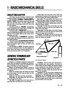
VEHICLE IDENTIFICATION Vehicle identification is given by two plates, one oval shaped plate fitted to the nears.ide (driver's side) inner wing and one rectangular plate (VIN plate) mounted on the nearside of the bulkhead. A breakdown of the entries on each plate is given in Figs. I and 2 respectively.
ENGINE NUMBER TIle engine identincation plate is to be found rivetted 10 the block and is in one of two formats (see Fig. 3) according to the space available on the block. A breakdown of the entries on the plate is given in the illustration.
TRANSMISSION NUMBER The transmission can be identified by means of a plale afftxed 10 the end cover on manual gearboxes or the torque converter housing on automatic transmission. The uppermost number relates to the transmission type while the bottom number is the fabrication number.
7
Pass the MoT When your Renault 18 or Fuego is three yean old, it must be submitted for its rust MoT test. The car must then be tested annuaUy to ensure that it is being maintained in a roadworthy condition. The test fee paid to the garage covers the cost of carrying out the inspection whether the vehicle passes the test or fails. so it makes sense to carry out your own pre-test check beforehand. Bear in mind that even 3 simple item like a parking lamp or one of the screen washers not working could "fail" the car. Obviously a DIY owner will not be able to examine a car to the same standard of inspection as an offw::ial tester, but you could avoid a needless failure certificate just by being aware of the checks that the tester will make. All the items that will come under the tester's scrutiny are included in this repair manual, a1though this book is not compiJed specifx:ally for passing the test. However , if you work your way tluough the items shown on tJlese two pages and tum to the appropriate page, you will have the infonnation required either to check or service the relevant campa. nents.
LIGHTING EQUIPMENT •......• Pages 24. 152 All external lights must be in working order including the headlamp main and dipped beam· and visible from a reasonable distance. Light lenses and reflectors must not be damaged or missing. The indicators must flash at the correct rate· between one and two flashes per second· and the panel warning lights must also be functioning. Headlamps must be correctly aligned. The stop lamps must illuminate whenever the foot brake is used.
STEERING •..• . ..... . . .. ....• Pages 21 . 114 Check for excessive play in all steering components from the road wheels to the steering wheel. Check for any unusual stiffness in the steering operation. The steering wheel should freely turn from one side through to full lock on the other side. Feel for play in the lower column universal joint, the rack mountings and steering ball joints. Examine the steering column bushes for wear by pushing the steering wheel back and forth as well as sideways. Examine the gaiters for any splits or tearing.
WHEEL BEARINGS ..•..... Pages 21. 123. 13 1 Raise and support each wheel in tum and check for bearing slackness or roughness by turning the wheel. A worn bearing will either be heard or felt at the tyre as the wheel turns. Grasp the wheel at the top and bottom then rock it to check for excessive or insufficient bearing clear· ance. If the bearings appear to be damaged or worn, or if there are any signs of grease leakage from the oil seals, the hub assembly should be overhauled. The condition should be checked whenever a wheel is off the ground, for whatever reason.
SEAT BELTS . .. • .. . . • . . .. •..•.•• . • . .... . ... .. . . . .. • . .•. . ..•..•......• .. . . . .. Page 25 The MoT tester will check the seat belts for security and the fabric for charmg and any obvious damage. Check the belt locking mechanism by puJUng slowly out of the top mounting, then sharply. The belt should instantly lock. The belt should retract smoothly once released. Check the belt and stalk moun ting points for security. There should be no struc· tural rust near the seat belt mounting points.
8
SUSPENSION • .. • . .•.••.•. Pages 21 . 123, 131 The vehicle will have to be raised and supported to check the suspension. Using a suitable long lever o r screwdriver to give leverage, check for excessive play in all the suspension joints and rubber mountings. Check for condition of the shock absorber units and MacPherson struts, looking for nuid leakage and the security of the upper and lower mountings. Examine the drive shaft bellows. The drive shaft joints can be checked trying to move the halves of the joint in opposite directions. Feel for movement or grating between the two shafts on the jOints. Under road test conditions a worn joint will be heard to 'knock' when accelerating under conditions of partial or full steering lock.
BRAKES .................. Pages 18, 20, 137 Check the operation of the brakes and handbrake. The pads and linings should be free of contamination and of adequate thickness. Check for brakes pulling to one side and ascertain the cause. Also check the condition of the flexible brake hoses, looking for signs of cracking or bubbling and for corrosion on the rigid metal pipes. Check thai the brake servo is working correctly (if fitted). The testing station will use a roller brake tester to check the efficiency of each wheel, including the handbrake mechanism. The brakes should not stick on after the handbrake is released. Check around the master cylinder and all of the brake pipe unions for fluid leakage.
WHEELS & TYRES ... . . .. •.•...... .Page 21
~
..
Check the condition of all tyres, including the spare. Check the tread depth around the circumference of each tyre and inspect the side walls, looking for cuts, bumps and bulges as well as sharp objects stuck in the rubber. See that all tyres are inflated to the correct pressures (this could affect the brake test). 'Run nat' type tyres must not be punctured. Check the tyre type. Steel and fabric belted radial tyres should not be mixed on the same car. Examine aU the road wheels, checking for damage and distortion. Make certain that wheel nuts or bolts are not missing, and are tightened adequately.
GENERAL ..•..•. . •.•.••... Pages 24, 57, 65 The windscreen wipers and washers should be working efficiently. Wiper blades do deteriorate so it is a sensi· ble rule to replace the rubbers or complete anns at least o nce a year. The horn should also operate clearly. Check that the exhaust system does not leak nor make an excessive amount of noise. Check the body for any damage or corrosion liable to render the car unsafe, especially all of the important load bearing areas· steering, suspension and the engine and transmission supports.
NOTE: The items mentioned 011 Ihese pages are Q guide so thallhe keen DIY owner can check his or her Renault 18 or Fuego before submillillg it [or the MoT rest. Although it is based 0 11 the a/flew/ MoT check list at the time o[publicalion, it is only Q guide Qlu] should be (reated as SIICh.
9
Selleck". WEEKLY OR WHEN REFUELLING • • • •
Check Check Check Check
tyre pressures and condition, including spare operation of aU lights and horn operation of windscreen wipers and washers condition of driving mirrors
• • • •
Check Check Check Check
windscreen , headlamp and tailgate washer levels coolant level engine oil level brake fluid level
EVERY S,oooMILES OR EVERY 6 MONTHS, WHICHEVER IS SOONER As for weekly check above, plus the following additional items • • • •
Check operation of handbrake and lever ratchet travel Change the engine oil Check/top up automatic transmission Check for brake fluid leaks/front brake pad wear
• Check condition/run of flexible hoses
• Check/top up manual transmission e Check operation of bulbs & warning lights e Check lyre condit ion/pressures
e Check wheel nut tightness e Check front / rear hub play
EVERY 10,000 MILES OR YEARLY , WHICHEVER IS SOONER As for S ,000 mile service, plus the following additional items • • • • •
Change oil filter Change engine oil Check front brake pad wear Check/adjust main/dipped beams Check underbody & exterior panels for corrosion
. e e e e
Check/adjust clutch operating clearance Check/adjust drive belt tension Check/adjust CO setting & idle speed Check/adjust dwell angle & timing Check/adjust/change spark plugs (contact breaker ignition)
EVERY 20,000 MILES OR 2 YEARS, WHICHEVER IS SOONER As for 10,000 mile service, plus the following additional items e • • • •
Check engine/transmission for leaks Check drive shafts for play/leaks Check/tighten sump bolts Check shock absorbers for leaks/loose mountings Check condition of exhaust system
• e e e e
Check fuel lines for leaks/co ndition Check visually all mechanical units Change fuel filter clement Change air filler element Check/adjust or change spark plugs
EVERY 40,000 MILES OR EVERY 4 YEARS , WHICHEVER IS SOONER As for 20,000 mile service, plus the following additional items
e Drain/ refill manual gearbox • Drain/refill automatic gearbox • Check for play/leaks front suspension/steering
e Adjust handbrake . Orain/ Oush/bleed cooling system e Change rocker shaft oil filter (829 Engine only)
EVERY 80 ,000 MILES OR 8 YEARS , WHICHEVER IS SOONER As for 40,000 mile service, plus the following additional items e Change toothed timing bell (829 Engine only)
10
Routine ·Maintenance INTRODUCTION .•........• .. • ... . . • . . [I ] JACKING PROCEDURES ........... .... [2] ENGINE OIL & FILTER . . .•.• . . .... . . . . [3 ] GEARBOX OIL . . . ..•.•..•..•.... . . . . . [4 ] AUTOMATIC TRANSM ISSION •....• . • . . . [ 5] BATTERY •.... .. . .. . . • . .. . ....•.•... [ 6] COOLING SYSTEM .. . . ... .. . . . ... .. •.• [7] BRAKE FLUID LEVEL . .. . . .. .. .. . . . ... [8] AIR FILTER. . . . .. . . . . .... .•• .. • . ... . • [9] DiSTRIBUTOR ...... . .. . . . ...... ..... [10]
DRIVE BELTS . . . .. .....•.•• • • . ••• . .. [ 11 ] BRAKES ... . . ...... .. . . . . • . ....••.. . [ 12] CLUTCH ADJUSTMENT ... .. • . . . .• . . . . [ 13] WHEELS & TYRES . . .....•.•.••••.. . . [ 14] STEERING & SUSPENSiON . . ... .. . . ..• [ I S] EXHAUST SySTEM . . •... . • . .. . . . ....• [ 16] LIGHTS & INSTRUMENTS .... . . .. . ..•. [ 17] WINDSCREEN WIPERS & WASHERS .•... [ 18 ] SEAT BELTS . .....•....•.. . . .. . . . . .. [1 9 ] GENERAL LUBRICATION .. ... .. .. . . . . [20 ]
INTRODUCTION ... . ......... ... . . ...• [1]
in the TUNE-UP chapter. ntis enables a complete engine tune to be carried out as a separate operation if required . The remainder of the Routine Maintenance checks and operations are contained in this chapter, although major overhaul operations are described in the relevant chapters . Before starting work, read through both of these chapters carefully so you are aware of the work entailed and the tools and parts required. All relevant data, such as capacities, clearances, etc., where not included in the text, can be found in the TECHNICAL DATA at the end of this manual.
The importance of regular servicing cannot be overemphasised . remember that 'prevention is better than cure'. Carrying out the servicing yourself will not only save you money but also give you the opportuni ty to get to know your car. The Service Schedule on the opposite page lists all the service checks and adjustments with the intervals at whlch they should be carried out . Cars which cover a low annual mileage , should be serviced on a time basis instead of mileage. The sequence in which items are given has been arranged to give a reasonably logical o rder of working around and under the car. It is therefore recorrunended that this be roUowed where possible. Apart from the necessary materials - oil, fllters, plugs, etc .. the most important requirement is time. If time is limited, the service can be split up into two or more sect· ions, and the remaining items carried out at a later date. The advantage of this is that the service can be spread out over several weekends rather than doing it all in one go. In this way, there will be no need to either hurry or skimp over any items, as each is important in its own way, even if it's only a check or inspection. Few tools apart from nonnal hand tools (spanners, screwdrivers, etc.) will be required. However, some tools will be specifically required for servicing. Given below, is a list of tools that will be worthwhile buying if servicing is to be carried out on a regular basis. Oil filter strap wrench Torque wrench I in. A/ F socket or ring spanner Brake adjuster tool Battery hydrometer Grease gun Oil can Tyre pressure gauge Items listed in the Service Schedule are covered in de· tail either in this, or the next chapter. For convenience. all items directly concerned with engine perfonnance and economy· e.g. plugs, pOints, valve clearances· are covered
JACKING PROCEDURES . •.•..• . • . ..... [ 2] All Renault 18 and Fuego models are fitted with four jacking points on the underbody side sills; two at the front behind the front wheel arches, and two at the rear in front of the rear wheel arches. These jacking points should only be used with the jack supplied with the car (Fig. A : I), Before raising any part of the car. make sure that the wheels in contact with the ground are securely chocked. If poSSible , the handbrake should be applied and the car left in gear, or in the case of automatic transmission, in the 'Park' position. Never rely on the jack alone except when changing a wheel, and even then, one wheel should be placed under the car to act as a cushion should the jack slip. To raise the front when working under the car, place a jack (preferably a trolley jack) under the gearbox with a strong piece of timber between the jack head and the two main body members· see Fig. A:2. To raise the rear of the car, place the jack head in the centre of the rear axle beam (Fig. A:3). To raise the side of the car, use a SUitably shaped wood block between the side sill and the jack in line with the front door (Fig. A:4). Support the body
Routine Maintenance
11
with axle stands under the body side frame members with wood spreader blocks. Never attempt to lift the car by jacking under any non load-bearing panel.
ENGINE OIL & FILTER ....... . ..•... . . [3) Oil Level Check It is essential that the oil level be maintained at the correct level. The oil level should be checked at least once a week, and always before a long run. If the engine has been running, wait a few minutes after switching off to allow the oil to drain back into the sump for a correct level reading. The car must also be standing on level ground when checking the oil level. The oil level dipstick and mter cap locations on the various engines are shown in Fig. A:S. The oil level should be maintained between the two marks on the dipstick (Fig. A:6), and must never be allowed to fall below the lower mark. On models with an engine oil level indicator, the Min and Max positions of the needle correspond to those positions on the dipstick (Fig. A:7). Remove the dipstick, wipe the end with a piece of clean tissue or lint-free cloth to remove the oil film. Re-insert the dipstick fully then withdraw it again to check the level. If the level is low, remove the oil riller cap from the rocker cover (Fig. A:5) and add oil to bring the level to the upper mark on the dipstick. Wait for a minute or so to allow the fresh oil to reach the sump before taking the dipstick reading. The level should not be above the upper mark. When the level is correct, refit the oil filler cap. Do not overfill as this may result in oil leaks and increased oil consumption.
Changing Engine Oil & Filter The engine oil and fdter should be changed at the recommended service intervals or more frequently under severe operating conditions. The most severe type of operation, and that whJch gives rise to a sludge fonnation inside the engine, is light engine loading, slow engine speeds and short journeys where the engine never reaches normal operating temperature. High speeds over long distances are generally kinder to the engine. Modern multigrade engine oils contain additives which go a long way towards preventing sludge formation, but even these have certain limitations. The oil should be changed when the engine is warm , after a run. Unless you have access to a pit, it will be necessary to raise the front of the car. either by jacking up as described previously, or by driving the front wheels up car ramps. NOTE: Before auempting to drive the car onto the ramps for the JlTSt time, check that there is sufficient clearance under rhe front spoiler or valonce to avoid dartwge. Place a suitable container under the engine sump drain plug. This is located under the lear of the sump pan (Fig. A:8). An old 5-litre oil can with the side cut out is
'2
ideal for this operation . Undo the drain plug using a universal drain plug spanner with a male fitting and drain the oil into the container. While the oil is draining, clean the sump plug and check the condition of the sealing washer. If in doubt , fit a new washer. When the oil has completely drained, refit the plug and tighten it. Do NOT overtighten as difficully will be met when draining next time . The oil nIter is of the throw-away cartridge type, and is located on the side of the engine block. On most engine types it is possible to remove the nIter from within the engine compartment, although on some engines, access is better from below. Place a suitable container under the mter to catch any oil spilt during removal. It should be possible to unscrew the filter by hand, but if not, a special strap wrench, such as that .mown in Fig. A:9 will be required to release it. A strap wrench can usually be obtained quite cheaply from a local car accessary shop. Unscrew the nIter from the engine and discard it. Thoroughly clean the nIter sealing flange on the engine block to remove all traces of oil and dirt. Make sure the rubber sealing ring on the new nIter is correctly located , and then apply a smear of clean engine oil to the sealing ring. Screw the new mter into position until the sealing ring just contacts the mounting flange, then tighten a further 3/4 tum . 00 NOT overtighten the mter as this may distort the seaJing ring and give rise to oil leakage. The engine oil should be added in two stages. Pour into the engine mler hole , the amount of oil corresponding to the sump capacity given in TECHNICAL DATA. Run the engine for a few minutes to circulate the oil, then stop the engine and check the dipstick level as detailed previously. Top-up the level to the upper mark on the dipstick as the new mter will have absorbed approximately 0.25 litres. NOTE: It is illegal to dispose of old oil by tipping it down the draill or burying it in the ground. Most local councils have a facility for oil disposal and use should be made of this. AlrenJ4til'cly, a local garage may be willing to dispose of the oil for you. Oil Leaks If oil is required more often tltan normal, suspect engine wear or an oil leak. Check fust alound the engine for obvious signs of oil leakage and then the exhaust for excessive 'smoking'. Also check the unders.ide of the engine for leaks at the following places: Oil sump drain plug, oil filter mount ing flange, generally around the timing gear end of the engine. If any evidence of oil leakage is found , the area should be wiped clean, then the engine run to confirm the source. If the leak is serious, remedial action should taken as soon as possible.
Routine Maintenance
Fig. A:2 Method of raising front of car
Fig. A: I Details of car jack location
"I
Fig. A:3 Method of raising rear of car
Fig. A:4 Raising side of car with wood spacer block
847 (C1J) Fig. A:S Engine oil dipstick and fdler cap locations
Routine Maintenance
13
GEARBOX OIL ........ ............... 141
Oil level The gearbox and fUlaJ drive units share a common oil supply. The oil level should be checked after the car has been standing on level ground for some time, as foaming of the oil during use will cause the level to rise and give an inconcct indication of the oil level. In many cases, if a pit is not available, the car will need to be raised and supported by an equal amount at both ends to give access to the gearbox. The oil level is checked at the nller/level plug hole on the side of the gearbox. see Fig. A: 10, and a special drain plug key. (obtainable from most car accessory shops) may be required to remove the plug if it has a square socket
h"d (Fig. A, 10). The gearbox oil level is correct when it reaches the lower edge of the hole. If necessary , top-up the level with the correct grade of oil as specified in the TECHNICAL
DATA using a plastic 'squeeze' bottle with a flexible tube attached. When the level is correct, refit the plug and tighten it sufficient to seal but do not overtighten. The gearbox/ fmal drive oil should be changed periodically as detailed in the Service Schedule. Undo the drain plug (Fig. A: 10) and drain the oil into a suitable container. Refit the drain plug and refdl the gearbox to the correct level · see TECHNICAL OAT A for capacity and oil grade.
NOTE: Lack of oil in the gearbox can only result from leakage. atJd this should be investigated if the level is low.
AUTOMATIC TRANSMISSION . . •..• . • . •• 151 Fluid Level The nuid level in the automatic transmission should be checked periodically . The fluid level is best checked immediately after a short run when the fluid will have reached its normal operating temperature. With the car standing on level ground, apply the handbrake fully, and with the engine idling, move the manual selector lever Uuough all pOsitions at least Uuee times. Now move the selector lever to the P (park) posit· ion, and allow the engine to idle for a further one to two minutes. The fluid level dipstick is located in the transmission fdler tube at the rear of the engine (Figs. A: 11 & A: 12) depending on the engine type . With the engine still idling, clean the outside of the mler tube to prevent dirt from entering the transmission, then withdraw the dipstick and wipe the end clean with a tissue or lint-free cloth. Reinsert the dipstick fully into the filler tube and when withdraw it again immediately. Check the fluid level indicated on the dipstick . it should be between the two marks inset in Figs. A: I I & A:
12. NOTE: The dipstick has 'Hot' upper 'Cold' lower level mIlrkings. select the appropriate mark for the level reading.
'4
If the level is low, top'llP with the specified type of automatic transmission fluid · see TECHNICAL DATA, through the dipstick tube, using a clean funnel and a suitable piece of tubing as necessary . Automatic transmission fluid is normally obtainable in plastic 'squeeze' bottles with a flexible spout. Take great care to avoid overflUing the transmission this wiU cause the fluid to become aerated with subse· quent overheating of the transmission. The transmission will only work properly when the fluid level is correct.
NOTE: The importance of cleanliness cannot be overemphasised when checking or lopping-up the fluid level as the slightest trace of dirt or inco"ect oil mIlY cause datnilge to the transmission. Fluid Change The fluid in the automatic transmission should normally be changed every 40,000 miles or 4 years. However, under arduous operating conditions, such as when towing a caravan for a high mileage or over mountainous terrain. it is advisable to change the fluid more often. A drain plug is fitted to the transmission oil pan or casing depending on the type (Figs. A:13 & A: 15), and this should be removed to drain out the fluid. A universal drain plug spanner with a male fitting will be needed to undo the plug. This 1001 can normally be obtained from most car accessory shops. Place a su ilable container of adequate capacity under the transmission to catch the fluid. Clean, refit and tighten the drain plug securely but do not overtighten. Refdl the transmission with the specified type of automatic transmission fluid· see TECHNICAL DATA . The amount of fluid required for a fluid change is 2.0 - 2.5 litres. depending on how much fluid has drained from the torque converter. First, pour in approximately 2 Iitres of fresh fluid in· to the transmission filler lube, using a funnel and suitable length of lube as necessary. With the handbrake and footbrake fully applied, start the engine and allow it to idle. Move the manual selector lever through all the positions with the car stationary. Now check the fluid level as detailed previously. Add fluid as necessary 10 bring the level up to the Cold full mark on the dipstick. Drive the car for a short distance until the engine and transmission fluid reaches normal operaling temperature . Recheck the fluid level as detailed previously and 10p-Up to the Hot level mark on the dipstick if necessary. NOTE: A low fluid level in the transmission can only
result from lea/wge, and the cause should be investigated as soon as possible to avoid damage /0 the tram;mission.
BATTERY ......... ...... ..... . ...... 161 Electrolyte Level Some Renault 18 and Fuego models are equipped from new with a 'maintenance·rree' battery which, as the name su ggests. should requIre no attention. These balleTles
Routine Maintenance
, r 2-...,.-
0
00
o
Fig. M: 11 Installing pads and caliper· Girling
Fig. M: 10 Retracting caliper piston· Girting 1. Safe ty clip 2. R etain ing key 3. Springs 4. Pad wear sensor wires
Fig. M: 13 Retracting caliper piston - Bendix series
Fig. M: 12 Front caliper· Bendix series 4
140
Brakes
Fig. M: 14 Chamfer pad retaining key
Fig. M: 15 Disengaging the actuating lever· Bendix
Fig. M: 17 Removing shoe retaining springs • Bendix
Fig. M: J6 Removing rear brake drum
Fig. M: 18 Releasing self adjusting link· Bendix
Fig. M: 19 Removing shoe link . Bendix
Fig. M: 20 Positioning toothed sector· Bendix
Fig. M:21 Self adjusting spring. Bendix
Brakes
141
cylinder pistons coming out of their bores. If this special tool is not available then a good al ternative is to twist a piece of wire rou nd the cylinder. 14. Protect the rear hub bearing against dirt by placing a plastic cup over the stub axle. 15. Qean all the brake dust and dirt from the inside of the backplate. If there are signs of grease or brake fluid on the backplate or brake shoes, then the cause should be investigated and rectified at this stage before the new shoes are fitted.
Installation Smear all the shoe pivot points with brake grease and reassemble the slotted link and spring, and the handb rake lever to the shoe. 2. Fit the shoes in the reverse order of removal and reconnect the handbrake cable. 3. The self adjusting mechanism will only work if the tension of spring 'A', Fig M:2 1, is correct. The clearance between the link and the leading shoe must be approximately 1 mm (Fig. M:22). If this dimension is not as specified, the link spring and both brake shoe return springs must be changed. 4. Refit the brake drum after centralising the shoes in relation to the backplate, adjust the hub bearing endfloat and pump the brake pedal several times to bring the shoes into correct adjustment. 1.
Removal - Girling I. Remove the brake drum as described in the previous section. 2. Unhook the handbrake cable and the upper ret urn spring. 3. Remove retaining clip and unhook the self adjusting mechanism ratchet spring and lever (Fig. M:23). 4. Retain the ratchet lever thrust washer fro m the pivot spindle. 5. Extract the shoe retaining pins' by gripping the upper washer with a pair of pliers, compressing the spring and turning the washer through 90 deg. Pull off the washer, spring and lower washer and extract the pin . 6. To stop the wheel cylinder pistons coming ou t of their bores they should either be retained with a piece of wire wrapped around the cylinder or, alternatively use Renault tool Fre. 05. 7. Remove the adjusting link (Fig. M:23), pull the brake shoes away from the wheel cylinder and cross them over. The bottom return spring can now be removed from behind its retaining clip. 8. The brake shoes can now be removed from the backplates. NOTE: The adjusting link on the right hand side is identified by yellow paint and the left hand side by grey paint.
Installation 1. Examine the wheel cylinder for any signs of brake fluid leaks and overhaul the cylinder if necessary as described in the Rear Brake Cylinders section of this chapter. 2. Fit the bottom return spring by hooking the ends through the shoes from the back as shown in Fig. M:24. 3. Refit the shoes and linkage in the reverse o rder of removal.
14 ,
4. Push the hand brake operating lever back against the brake shoe and rotate the ratchet until the diameter, measured across the linings, is approximately 178 mm. When this dimension is correct fit the top return spring. 5. Reconneci the handbrake cable and refit the brake drum. 6. Reset the hub bearing endfloat and adjust the brake shoe clearance by depressing the pedal several times to actuate t he self adjusting mechanism. 7. Oleck the handbrake travel and adjust as described in the Handbrake Cable section of this chapter. 8. Refit the wheels, jack up the car, remove the axle stands, lower the car to the ground and tighten the wheel bolts to the correct torque setting - see TECHNICAL DATA.
REAR BRAKE PAD REPLACEMENT •..• .. [4] Replacement I. Slacken the rear wheel bolts, jack up the rear of the car and support on axle stands. Remove the wheel. 2. Remove the pad retaining clips and extract the outer pad. 3. Swing the caliper inwards and remove the inner pad. 4. Install in the reverse order of removal.
BRAKE HYDRAU LlC CI RCUIT ... • . ...•• [5] Overhaul of the components of the hydraulic system should always be carried out under conditions of scrupulous cleanliness. Qean all dirt and grease from the exterior of components before removal and dismantling. After dismantling, wash all parts in commercial alcohol, methylated spirits or clean brake fluid_ Do NOT use mineral based oils such as petrol, paraffin or carbon tetrachloride_ Blowout all internal passages with compressed air. Inspect pistons and cylinder bores of the master cylinder, looking for scores, ridges or corrosion pits. The unit MUST be discarded if any of these conditions are present. The calipers and wheel cylinders should also be inspected for leaks and signs of wear after dismantling. If any signs of wear are present, the unit must be replaced. It is essential that only new seals are used when reassembling. These are nonnally available in the fonn of a repair kit containing all the necessary parts required for the overhaul of a particular unit. Ail seals should be inspected carefully before fitting, even when new. Oleck that the sealing lips are perfectly fonned, concen tric with the bore of the seal, and free from 'knife edge' cuts, surface blemishes or marks. Any seal which does no t appear perfect, no matter how minute the blemish may appear to be, should be discarded.
BLEEDING THE HYDRAULIC CIRCUIT .. • [6] The fluid level in the brake master cylinder must be maintained at a reasonable level throughout the bleeding operation as, if allowed to drop excessively, air may be drawn into the system .. Use only fresh hydraulic fluid of the correct specification. see TECHNICAL DATA. Never re-use fluid which has already been passed
Brakes
r
1. Upper rdurn 'pring
2. Ralchet lever 3. Adjusting /ink
4. Shoe reta;"lng cUp .5. Bottom return 6. Ratchet
Fig. M: 22 Shoe link clearance - Bendix
Fig. M:23 Rear brake assembly - Girling
Fig. M:24 Engaging retwn spring Girling
Fig. M:2S Caliper bracket retaining bolts
fig. M:26 Removing brake disc from bub
Fig, M:27 Front brake disc - Fuego I. 2. 3.
4. 5
Boo t Piston Seal Spring Cylinder
--3
4
---2 1
Fig. M:28 Rear brake cylinder bolts
Fig. M:29 Rear brake cylinder - Girting
Brakes
143
through the system. Take care when topping up the master cylinder with fluid since it is an effective paint st ripper, and any spilt on the bodywork should be washed off with cold water immediately. 1. The vehicle should be standing on level ground when bleeding the brakes, not up at one side or end. 2. Remove the reservoir cap and top up the reservoir, making sure both chambers are topped up with the reconunended fluid. Note that the fluid level should be topped up regularly during the bleeding operations. 3. Oean the right-hand (offside) front brake caliper bleed nipple and attach a bleed tube. 4. Immerse the other end of the tube in a clean jar containing a small quantity of clean brake fluid. Throughout the bleeding operation, the end of the tube must remain immersed in this fluid. 5. Slacken the bleed nipple approximately half a turn and then depress the brake pedal fully, allowing it to return to the fully released position. Brake flu id and/or air should have been pumped into the jar. If not, slackcn the bleed nipplc further until fluid and/or air can bc pumped into the jar. 6. Continue depressing the brake pedal, pausing briefly (about three seconds) after each stroke, until the fluid coming from the bleed tube is completely free of air bubbles and is perfectly clean. 7. Finally with the brake pcdal in the fully depressed position , close the blced nipple. Take care not to overtighten the nipple; tighten it only enough to seal it. 8. Remove the bleed tube and transfer it to the lefthand (near-side) rear brake. 9. Repeat the bleeding operation, connecting the rube to the nipple located on tbe brake backplate. 10. Repeat the bleeding operation on the left-hand (nearside) front brake, followed by the right-hand (offside) rear brake. II. Top up the master cylinder with approved fl uid and replace the cap, after first checking that the vent hole in it is clear. Do not fill the reservoir above the MAX mark on the side. 12. Oleck the operation of the brakes. If after bleeding, the brake pedal is still 'spongy', or goes right down to the floor , this indicates that air is still present in the system, and the bleeding operation must be repeated. If subsequent attempts at bleeding still fail to produce a satisfactory result , the system should be checked for leaks, as air is obviously being drawn into the system.
BRAKE PIPES & HOSES •.. . . .. •••. . . • .• [7] Brake pipes and hoses should be inspected fo r corrosion and leakage (Fig. M: I), and should be replaced if at all suspect. Flexible hoses should be replaced as a matter of course every 3 years 36,000 miles. If the pipes come loose from their clips they may vibrate and fatigue fracturing may result. Brake pipes rust especially between the body and the pipe, and should have any mud waShea off to aid inspection. When fitting a new pipe or replacing an old fitting, the tube nuts should be tightened to a torque of approximately 8 Ib f1. Take care not to overtighten the nut or the fitting will distort and leak. Use only short spanne rs to avoid the risk of damage.
144
Before fitting a tube nut, ensure that both sides of the connection are clean and free from grit, which will prevent the joint from seating. Whenever a hydraulic fitting is disturbed, the brake system should be bled as described previously.
FRONT BRAKE CALIPER BRACKET ... . . [8] Removal
I. Slacken the wheel bolts, jack up the front of the car and support on axle stands. Remove the road wheel. 2. Remove the caliper and piston assembly as detailed in the Front Brake Pad Replacemcnt section of this chapter. Do not disconnect the hydraulic hose or let the weight of the caliper hang unsupported. 3. Extract the disc pads as previously described and put to one side. 4. Undo the two caliper bracket retaining bolts and remove the bracket (Fig. M:2S). Installation I. Install in the reverse order of removal but before reo fitting the caliper bracket bolts apply thread locking com· pound to the threads. 2. Install the disc pads and caliper as described previously. 3. Pump the brake pedal several times to bring the pads into contact with the disc.
FRONT BRAKE DISC . . . .. . . . .... . .. . . . [9] Removal - Early Models Except Fuego 1. Remove the brake caliper and caliper bracket as previously described . 2. Pun off the brake disc and hub assembly as described in the FRONT SUSPENSION chapter of this manual . 3. Mount the assembly in a soft jawed vice and undo the six retaining bolts. The disc can now be separated from the hub fla nge (Fig. M:26).
Inspection
Inspect the disc friction surfaces. Moderate scoring is permissible, but heavy scoring or grooving, cracking or pitting of the surfaces, or excessive corrosion build up necessitates the replacement of this disc. The disc may be trued up by grinding down to within the minimum permissible thickness specified in TECHNICAL DATA, but repl~cement is preferable. Make sure all disc/hub mating surfaces are free from dirt and corrosion. Also make sure that the friction surface of the disc is free from dirt, oil and brake fluid. Installation
1. Bolt the disc to the hub flange, carefully tightening the bolts evenly to avoid causing distortion. The bolts should be tightened to the corrcct torque figure - see TECHNICAL DATA. 2. Refit the hub assembly, brake caliper bracket and caliper. Pump the brake pedal several times to bring the
Brakes
pads into contact with the disc. Tighten the hub nut to the specified torque· see TECHN ICAL DATA. 3. Refit the road wheel, remove the axle stands, lower the car to the ground and fully tighten the wheel bolts.
Remova l · Negative O ffset Su spension 1. Remove the brake pads and the brake caliper as previously described. 2. Undo the two brake disc retaining bolts (Fig. M:27). These bolts have Torx heads (size T 30) req uiring a suit· able special tool for removal, which is available from most good car accessory shops or tool dealers. 3. The disc should now come away from the hub fla nge, but if not the drive shaft nut should be loosened slightly to allow more clearance.
Installation 1. Inspect the condition of the brake disc as detailed in the previous section of this chapter. 2. Fit the brake disc onto the h ub and tighten the Torx screws. Tighten the driveshaft nut to the correct torque if necessary· see TEC HNICAL DATA. 3. Refit the brake caliper and pads and pump the brake pedal several times to bring the pads into contact with the disc.
REAR BRAKE CYLINDERS ..... ... . ... [10[ Two alternative types of rear brake cylinders are used on Renault 18 and Fuego models. One is manufaClUred by Bendix and the other by Girling, but although there are slight differences, the replacement and overhaul pro· cedures are identical.
Removal I. Remove the rear brake drum· see Rear Brake Shoe Replacement section of th is chapter. 2. Disconnect the upper return spring from the brake shoe linkage and pull the shoes apart. 3. Block the hydraulic system by sealing the master cylinder reservoir as previously described. 4. Undo the pipe union at the rear of the cylinder and remove the pipe. Block the end to prevent d irt ingress and loss of hydraulic fluid (Fig. M:28). 5. Undo the two cylinder mounting bolts and remove the cylinder from the brake backplate (Fig. M:28).
Installation This is a reversal of the removal procedu re, noting that the hydraulic circuit must be bled as desc ri bed pre· viously at the beginning of this chapter.
Overhaul (Fig . M : 29& M:30) I. Remove the brake cylinder as described previously. 2. Pull the rubber boots from the ends o f the cylinder and withdraw the piston assemblies. Separate th e boots from the pistons. 3. Slide Oul the piston seals and then remove the spring from the centre of the cylinder bore. 4. Clean all the components with methylated spirits or clean brake fluid , wiping them dry with a lint free cloth. Check the pistons and bore for scoring and p itting· this
is important. If any component is badly scored or pitted it must be replaced. 5. Assem ble the rubber boots to the pistons. 6. Lubricate the piston, cylinder bore and seals with clean brake fl uid. 7. Fit one piston and boot to the cylinder. 8. From the open end of the cylinder, slide in a new piston seal, spring and second seal, making sure the open ends of the seal face the spring. 9. Fit the second piston and rubbe r boot. 10. Refit the cylinder to the brake backplate and connect the brake pipe. II. Refi t the brake shoe return spring and the brake drum. 12. Bleed ou t the hydraulic system, refit the road wheel, lower the car to the ground and fully tighten the wheel bolts.
REAR BRAKE DISC ......... .. .. . .... ["1 Replacement I. Slacken the rear wheel bolts, jack up the rear of the car and support on axle stands. Remove the wheels. 2. Remove the brake pads as described in the previous section. 3. Undo the two caliper bracket fIXing bolts (Fig. M:31) and ease the caliper clear of the disc, carefully flexing the hydraulic p ipe without kinking it. 4. Undo the two bolts holding the disc to the hub (Fig. M,32). These have Torx T30 heads which require a special tool which can be obtained from most good accessory shops. 5. The disc can now be removed from the hub. The rear discs cannot be reground and therefore if any uneven wear, pitting, or cracking is present the disc must be replaced. 6. Install in the reverse order of removal observing the correct torque setting for the disc retaining bolts and the caliper bracket bolts· see TECHNICAL DATA.
REAR BRAKE CALIPER . ... . . .. . .. . .. [121 Replacement I. Block the hydraulic system by sealing the fluid reser· voir as described previously. 2. Slacken the rear wheel bolts, jack up the rear of the car and support on axle stands. Remove the rear wheels. 3. Detach the handbrake cable from the operating lever on the caliper. 4. Undo the hydraulic pipe union at the bottom of the caliper (Fig. M:3 1) and block the end to prevent fluid loss and the ingress of dir t. 5. The caliper can now be removed from the mounting bracket. 6. Remove the brake pads. 7. LnstaJl in the reverse order of removal. 8. Bleed the air from the hydraulic system and check the adjustment of the handbrake.
Overhaul I.
Brakes
Remove the caliper as described in the previous sect·
145
ion of this chapter. 2. Mount the caliper in a soft jawed vice. 3. Using a small screwdriver, remove the dust cover from the end of the piston. 4. Apply a source of compressed air to the hydraulic fluid port and simultaneously unscrew the piston using a square section tool such as a screwdriver shaft (Fig. M:33). The piston must be protected from contacting the caliper body by using a suitable block of wood as shown in Fig. M:34. If the piston is damaged in any way it must not be re·used. 5. Using a smooth metal or plastic instrument such as a feeler gauge or a plastic knitting needle, remove the piston seal from its bore. 6. Oean all the parts in methylated spirits or clean brake fluid. Do not use mineral based oils such as petrol or para· ffin. Inspect the surface of the piston and the condition of the bore for pitting, scoring and cracking. If any of these conditions are present the caliper mu st be replaced with a new one. 7. Lubricate the piston seal with clean brake fluid and fit it to the groove in the bore. 8. Lubricate the piston with clean brake fluid and push it gently into the bore being careful to avoid damaging the seal. 9. Finish screwing the piston into the bore using a square section tool. When the piston is fully retracted it will turn without entering any further. 10. Turn the piston carefully until the groove (1. Fig. M:3S) is aligned with the bleed nipple (2, Fig. M:3S). This ensures thai the caliper can be bled easily and the pad will fit correctly in the centre slot. II. Apply a smear of Spagraph grease 10 the exposed area of the piston and fit the dust cover carefully locating it in the retaining groove.
BRAKE MASTER CYLINDER ....• . ..•• [13] The brake master cylinder fitted to Renault 18 and Fuego models is either of Teves or Bendix manufacture. The removal and installation procedures are identical, but the overhaul method differs slightly.
Removal 1. Remove the reservoir cap and drain all the fluid from the reservoir chambers by opening the bleed nipple on both front calipers. Close the bleed nipple when the reo servoir is empty. 2. Carefully lever the fluid reservoir from the master cylinder body and remove the rubber sealing grommets. 3. Undo the two retaining nuts and separate the master cylinder from the vacuum servo. The unit can now be removed from the car.
Installation I. Installation is a reversal of the removal procedure, but the length of push rod protruding from the servo front face should be 0.354 in (9 mm) see A, Fig. M:38. If this dimension is incorrect the rod should be ad· justed before proceding. 2. Refit the master cylinder and tighten the retaining nuts.
'46
3. Refit the hydraulic pipes, ensuring that they are installed in the correct order - see Fig. M:39. 4. Fit new sealing rings 10 the master cylinder and push the reservoir down as far as it will go. 5. Fill the reservoir with fresh brake fluid and bleed the air from the system.
Master Cylinder Overhaul· Teves (Fig. M:36) I. Remove the master cylinder assembly as described in appropriate section of this chapter. 2. Mount the cylinder in a soft jawed vice and lever off the fluid reservoir. 3. Compress the piston return spring by pushing a small screwdriver in the pushrod end of the cylinder. Undo the stop screw (Fig. M:40) and remove the circlip from the end of the cylinder bore. 4. Release the pressure on the return spring and lift out the primary piston and spring. 5. Blowout the secondary piston and spring using compressed air, but place some cloth over the end of the cylinder to avoid losing any of the components. 6. Oean the master cylinder and pistons with methylat. ed spirits or clean brake fluid. Do NOT use mineral based oils such as petrol or paraffin. Dry the components using a lint free cloth or blow them dry with compressed air. 7. Inspect the pistons and master cylinder bore for visible score marks pitting or corrosion. This is important, if any of these conditions is evident, the component must be renewed. 8. Lubricate the cylinder bore and components with clean brake fluid. 9. Fit the secondary piston assembly followed by the primary piston assembly. 10. Compress the piston return springs and install the stop screw. II. Install the washer and circlip in the end of the cylinder bore. 12. Fit new sealing rubbers in the master cylinder body and push the fluid reservoir down as far as it will go onto the cylinder. 13. Refit the master cylinder assembly as described previousJy and bleed the brakes. After bleeding, depress the brake pedal and hold it depressed for approximately ten seconds. Examine the master cylinder to ensure that there arc no signs of fluid leakage.
Master Cylinder Overhaul · Bendix (Fig. M: 37) 1. Make up a tool to the dimensions shown in Fig. M:41. from 0.25 in (6 mm) diameter steel rod. 2. Compress the primary and secondary piston assemblies with the tool as shown in Fig. M:42. 3. Place a 3,5 mm drill horizontally in a vice, then position the master cylinder so thai the drill enters the secon· dary piston roll pin (Fig. M:43). 4. Rotate the master cylinder round the drill until it grips the roll pin, then pull the master cylinder to withdraw the roll pin. 5. Repeat the previous procedure to remove the primary roll pin. 6. Withdraw the primary and secondary piston assem· blies from the cylinder bore.
Brakes
1. 2. 1. 4.
.s.
Boot Pilton Seal Cylinder Spring
1
Fig. M:30 Rear brake cylinder. Bendix
Fig. M:31 Rear caliper bolts
Fig. M:32 Rear disc retaining screws
Fig. M:33 Winding piston into bore
2
Fig. M:3S Aligning caliper piston
Fig. M:34 Ejecting caliper piston
J
Srop sc . .....
2
C..clip
] 4
W/Uh ... I'Inon ( f'r(mary j I'I'Hon (Suonda,~ )
S. 6
Fluid , tU"OO;'
7.
Stallnx ritlJl
Fig. M:37 Master cylinder· Bendix
Fig. M:36 Master cylinder. Tel'ts
Brakes
147
7. Oean the cylinder bore and the piston assemblies with methylated spirits or dean brake fluid and check the condition of the parts. Look for signs of scoring and pitting or wear ridging. If any of these conditions are apparent, then the master cylinder should be discarded and a new unit filled. 8. If the master cylinder is suitable for reconditioning, then remove the old seals from the piston assemblies and fit new seals. Note which way round the seal lips are filled before removing them. NOTE: The indivwUJII parts which make up the primary
and secondary pistons should not be dismantled If the pislons are worn, tIle assembly must be replaced. Only Ihe seals can be renewed individuaOy. 9. Lubricate the inside of the cylinder bore and piston assemblies with clean brake fluid and refit them in the reverse order of removal, making sure that the siots in the ronpins are in the vertical position. 10. Fit the previously described spring compressing tool and then insert the roUpins, taking care to align their slots facing the pushrod end (Fig. M:44). II. Fit new rubber seals to the reservoir ports and push the reservoir onto the cylinder as far as it will go.
BRA KE LIMI T ER . ....••.. . . ... ...•. . . [14J Remova l I. Block the hydraulic system by sealing the master cylinder cap as previously described. 2. Undo the union on the metal pipe feeding the limit· ing valve. 3. Loosen the union at the valve end of the flexible hose. 4. Undo and remove the nuts securing the actuating rod to the valve ann. S. Undo and remove the two bolts holding the valve to the underside of the car. The valve can now be removed from the car.
Installation 1. The brake limiter cannot be repaired and therefore it must be replaced if its' operation is not satisfactory. 2. Bolt the valve to the underside of the car. 3. Fit and tighten the metal pipe union to the valve. 4. Screw in the flexible hose union and tighten, ensuring that the pipe does not become twisted. If the pipe is twisted the union at the three way adaptor end of the hose must be slackened and offset one notch. 5. Remove the seal from the master cylinder and bleed the air from the hydraulic system as described under the appropriate heading in this chapter. 6. Connect the actuating rod and adjust using the procedure described in the follOwing section. 7. If the flexible hose is being renewed, the copper washers either side of the three way union must be check· cd for thickness. The correct thickness is 1,5 mm and new washers should be used if the measured thickness varies greatly from this figure.
Adjusting Before the limiting valve is adjusted the car must be parken on level ground with the luggage space empty and a person of average weight silting in the drivers seat.
1.
' 48
2_ Remove one of the rear wheel cylinder bleed screws and fit Renault special pressure gauge Fre. 214·02. 3. Bleed the air from the system using the bleed nipple located on the pressure gauge. 4. Tighten the bleed nipple and press the pedal several times, noting the cut off pressure. 5. Compare the pressure reading with the figure given in TECHNICAL DATA and adjust if necessary by screwing up the actuating link to increase the pressure or screwing it down to lessen it. 6. (beck the cut off pressure several times after adjustment to ensure that the setting is correct. 7. Disconnect the pressure gauge and bleed the air from the system.
BRAKE SERVO ..... . .... . • . ... .... . . [ 15J Remova l I. Disconnect the battery and place a tray under the master cylinder to catch the brake fluid as the pipe unions are undone. 2. Undo and disconnect the brake pipes from the master cylinder and drain the fluid from the reservoir into a con· tainer. 3. Undo the nuts securing the master cylinder to the servo unit and remove the master cylinder. 4. Disconnect the vacuum hose from the servo check valve. 5. From the inside of the car, disconnect the hrake pedal clevis pin from the pushrod yoke. 6. Undo the nuts securing the servo unit to the bulkhead. 7. Carefully remove the servo unit from the engine comp::artment.
Installa ti o n 1. Before installing the servo adjust the pushrod so that dimension 'A' Fig. M:38, is 9 mm and dimension '8' is 126mm. 2. Position the servo on the bulkhead and tighten the retaining nuts from inside the car. 3. Connect the push rod clevis to the brake pedal. 4. Fit the master cylinder to the servo body and con nect the pipes in the correct o rder as shown in Fig. M:39. 5. Connect the vacuum hose to the servo check valve and tighten the securing clip. 6. Fill the master cylinder reservoir with fresh fluid and bleed the air out of the system.
HANOBRAKE CABLE .. . . . .. ... .. . . .. . [ 16J Ensure the correct operation of the mechanism for the rear brakes it is essential brake cable is adjusted correctly. The car tioned with all four wheels on the ground brake lever fully released.
self adjusting that the handmust be posi· and the hand·
Adjustment I. Slacken the locknut and adjust the position of nut (I, Fig. M:4S) so that the cable can only be deflected by approximately ~O mm (2, Fig. M:4S). Do nol over adjust the cable as this will prevent the self adjusting mechanism
Brakes
1. To. R. H. front wheel
\::::~;;~;l,;::~~2~'lT~O)Li;.~H~., fran t wheel
\....
Fig. M:38 Servo pushrod adjustment
Fig. M:39 Master cyLinder pipes
r [ Fig. M:40 Master cylinder stop screw
55
215
Fig. M:41 Piston compressing tool
Fig. M:43 Withdrawing roUpin
Fig. M:42 Compressing master cylinder pistons
,
J.I
/1
/
2
,
1
/
I.
~
1. 2.
Adjusting nut Cable deflection
~
Fig. M:4S Handbrake cable adjustment
Fig. M:44 Aligning roUpin slots
Brakes
-
149
operating correctly. 2. The hand brake lever travel should be at least 9 notches (12 notches on cars fitted with disc Tear brakes).
10. Adjust the cable as described in the previous section of this chapler.
BRAKE PEDAL .. . . • ... .. . • .. . . .• .... [ 17J
Replacement
Removal
1. Loosen the wheel boits, jack up the car and support on axle stands. Remove the wheels. 2. Using a screwdriver inserted through the brake backplate, push the operating lever towards the drum to release it from the brake shoe. 3. Remove the grease cap from the hub using a suitable screwdriver, pull out the split pin, and remove the locknut and stub axle nut and washer. 4. Pull off the brake drum using a suitable three legged puller or Renault special tool T. Av. 235. 5. Unhook the upper return spring and pull the shoes away from the hydraulic cylinder. Secure the pistons in their bores by twisting a piece of wire round the cylinder. 6. Disconnect the cable from the operating lever using Renault special tool number Fre. 573 o r by pulling the end nipple with a self - grip wrench. 7. Remove the backplate mounted cable stop and unhook the cable from the guide stop on the underbody. 8. Undo the locknut and remove the adjusting nul from the handbrake lever link rod. The cable can now be removed from the car. 9. Refit in the reverse order of removal, but ensure that the hub bearing endfloat is set correctly - see REAR SUS· PENSION chapter. Also the grease cap should be filled with fresh grease before refitting.
1. Remove the under dash trim below the slee ring wheel. 2. Disconnect the clutch cable, on manual transmission models, al both the pedal and operating lever. 3. Remove the pedal shaft retaining clip and withdraw the clutch pedal. 4. Remove the clevis pin from the brake pedal push rod. 5. Unclip the second pedal shaft retainer and withdraw the pedaJ and shaft.
Installation 1. Oteck the length of the servo pushrod and adjust if necessary so that dimension ' B' Fig. M:38 is 126 mm. 2. Apply grease to pedal shaft , fit the pedal to the shaft and refit the shaft. 3. Reconnect the brake pedal to the push rod and refit the clevis pin and retaining clip. 4. Refit the clutch pedal and return spring, on manual transmission versions. S. Fit the securing clip to the clutch pedal end of the pivot shaft. 6. On manual transmission cars reconnect the clutch cable to the operating lever and adjust to give the correct clearance - see ROUTINE MAINTENANCE. 7. Refit the trim panel above the pedal.
BRAKES Trouble Shooter FAULT Excess ive hrake pctl .....~~;.!1~,~.
41 -
-'"''~=-''''' ,,,.,,
"~
®